On-line Reconfiguration Interoperability Test Suite
(OLR) Version 2.0.0
Last Modified: August 14, 2006
DSL Consortium 121 Technology Drive, Suite 2 University of New Hampshire Durham, NH 03824 InterOperability Laboratory Phone: +1-603-862-2911 Fax: +1-603-862-4181
Acknowledgments The University of New Hampshire would like to acknowledge the efforts of the following individuals in the development of this test suite. Tim Clark University of New Hampshire Tomas Elder University of New Hampshire Ian Katz University of New Hampshire Ben Klaas Occam Networks Matthew Langlois University of New Hampshire Jason Walls University of New Hampshire Dov Zimring Occam Networks
The University of New Hampshire InterOperability Laboratory
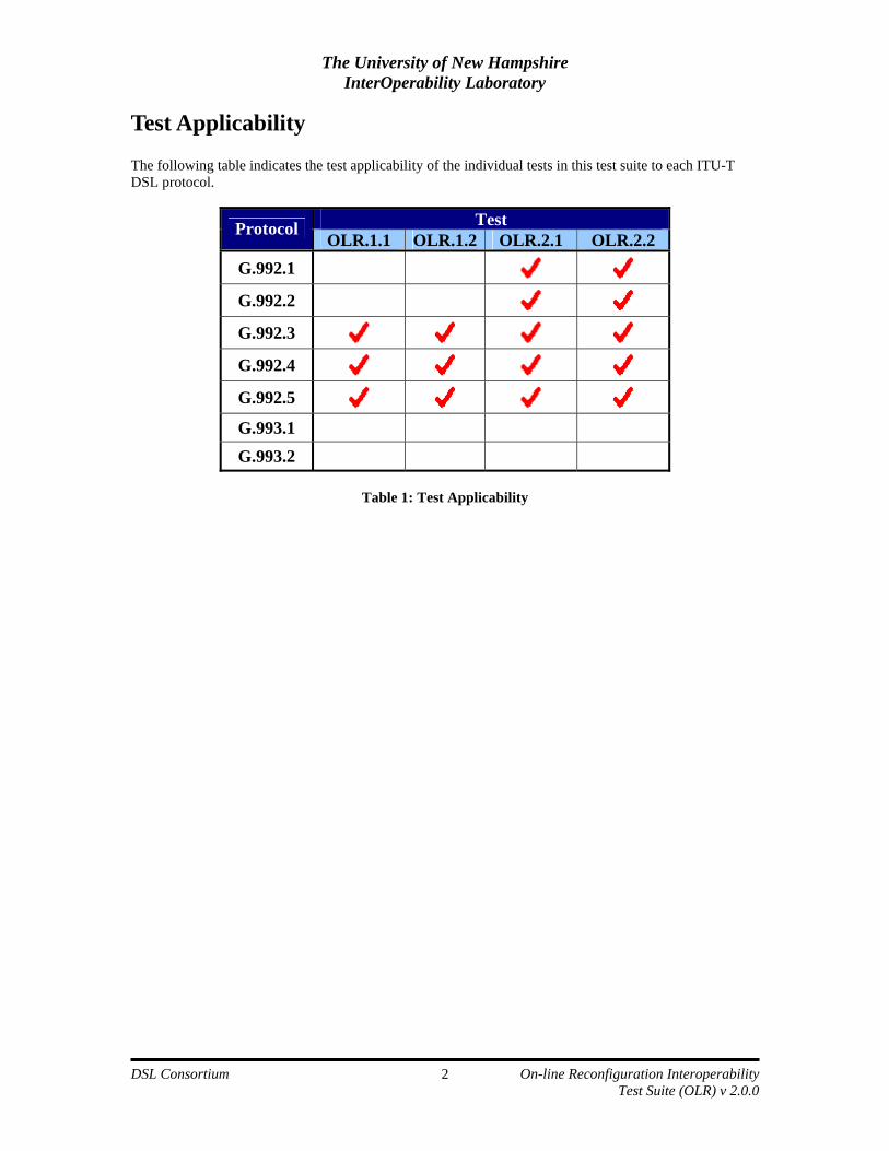
Modification Report........................................................................................................................................ i Acknowledgments .......................................................................................................................................... ii Table of Contents.......................................................................................................................................... iii Introduction ...................................................................................................................................................iv References......................................................................................................................................................vi Terms, Definitions and Abbreviations .........................................................................................................vii Test Setups .................................................................................................................................................. viii Background.................................................................................................................................................... 1 Test Applicability ........................................................................................................................................... 2 Group 1: ADSL2 Seamless Rate Adaptation Tests....................................................................................... 3
Test OLR.1.1: SRA Functionality in the Presence of Increasing Noise .............................................. 5 Test OLR.1.2: SRA Functionality in the Presence of Decreasing Noise ............................................. 8
Group 2: ADSL Bit Swap Tests................................................................................................................... 11 Test OLR.2.1: Bit Swap Functionality Test......................................................................................... 12 Test OLR.2.2: Bit Swap Stress Test ..................................................................................................... 14
Annex A: Results Grids ............................................................................................................................... 16 Group 1 Results Grid Legend............................................................................................................... 16 Test OLR.1.1: SRA Functionality in the Presence of Increasing Noise ............................................ 17 Test OLR.1.2: SRA Functionality in the Presence of Decreasing Noise ........................................... 18 Group 2 Results Grid Legend............................................................................................................... 19 Test OLR.2.1: Bit Swap Functionality Test......................................................................................... 20 Test OLR.2.2: Bit Swap Stress Test ..................................................................................................... 21
The University of New Hampshire InterOperability Laboratory
The University of New Hampshire’s InterOperability Laboratory (UNH-IOL) is an institution designed to improve the interoperability of standards based products by providing an environment where a product can be tested against other implementations of a standard. This suite of tests has been developed to help implementers evaluate the functioning of their DSL implementations.
The tests do not determine if a product conforms to the specifications, nor are they purely interoperability tests. Rather, they provide a method to isolate problems within a device. Successful completion of all tests contained in this suite does not guarantee that the tested device will operate with other devices. However, these tests provide a reasonable level of confidence that the Device Under Test will function well in most multi-vendor environments.
Organization of Tests: Each test contains an identification section that describes the test and provides cross-reference information. The discussion section covers background information and specifies why the test is to be performed. Tests are grouped in order to reduce setup time in the lab environment. Each test contains the following information:
Test number The Test Number associated with each test follows a simple grouping structure. Listed first is the Test Group Number followed by the test's number within the group. This allows for the addition of future tests to the appropriate groups of the test suite without requiring the renumbering of the subsequent tests. Purpose The purpose is a brief statement outlining what the test attempts to achieve. This also includes background information on why one needs to perform such a test to show that the device complies with the standard. References The references section lists standards and other documentation that might be helpful in understanding and evaluating the test and results. Resource requirements The requirements section specifies the hardware, and test equipment that will be needed to perform the test. The items contained in this section are special test devices or other facilities, which may not be available on all devices. Last modification This specifies the date of the last modification to this test. Test setup The setup section describes the configuration of the test environment. Small changes in the configuration should be included in the test procedure. Discussion The discussion section is optional. It is a general discussion of the test and relevant section of the specification, including any assumptions made in the design or implementation of the test as well as known limitations. Procedure The procedure section of the test description contains the step-by-step instructions for carrying out the test. It provides a cookbook approach to testing, and may be interspersed with observable results.
The University of New Hampshire InterOperability Laboratory
Observable Results The observable results section lists occurring events that can be examined by the tester to verify that the DUT is operating properly. When multiple values are possible for a specific event, this section provides a short discussion on how to interpret them. The determination of passing or failing a certain test is often based on the successful (or unsuccessful) detection of a certain predetermined event. Possible problems This section contains a description of known issues with the test procedure, which may affect test results in certain situations. Flow Chart: The flow chart section is optional. It provides a visual representation of the test procedure to facilitate a better understanding of the test.
The University of New Hampshire InterOperability Laboratory
[1] International Telecommunication Union Standardization Sector (ITU-T). Series G: Transmission Systems and Media, Digital Systems and Networks: Digital sections and digital line system – Access networks. Asymmetric digital subscriber line transceivers 2 (ADSL2), ITU-T Recommendation G.992.3, February 2004.
[2] International Telecommunication Union Standardization Sector (ITU-T). Series G: Transmission
Systems and Media, Digital Systems and Networks: Digital sections and digital line system – Access networks. Asymmetric digital subscriber line (ADSL) transceivers Extended bandwidth (ADSL2plus), ITU-T Recommendation G.992.5, January 2005.
[3] International Telecommunication Union Standardization Sector (ITU-T). Series G: Transmission
Systems and Media, Digital Systems and Networks: Digital sections and digital line system – Access Networks. Physical Layer management for digital subscriber line (DSL) transceivers, ITU-T Recommendation G.997.1, May 2003.
[4] International Telecommunication Union Standardization Sector (ITU-T). Series G: Transmission
Systems and Media, Digital Systems and Networks: Digital sections and digital line system – Access networks. Splitterless asymmetric digital subscriber line transceivers 2 (splitterless ADSL2), ITU-T Recommendation G.992.4, July 2002.
[5] DSL Forum Technical Report 067 (TR-067). ADSL Interoperability Test Plan, May 2004.
[6] International Telecommunication Union Standardization Sector (ITU-T). Series G: Transmission
Systems and Media, Digital Systems and Networks: Digital transmission systems – Digital sections and digital line system – Access networks. Asymmetric digital subscriber line (ADSL) transceivers, ITU-T Recommendation G.992.1, June 1999.
[7] International Telecommunication Union Standardization Sector (ITU-T). Series G: Transmission
Systems and Media, Digital Systems and Networks: Digital transmission systems – Digital sections and digital line system – Access networks. Splitterless asymmetric digital subscriber line (ADSL) transceivers, ITU-T Recommendation G.992.2, June 1999.
[8] University of New Hampshire InterOperability Laboratory (UNH-IOL) DSL Consortium, “DSL
Physical Layer Interoperability Test Suite (APLIT) Version 3.2.1.” March 2006.
[9] Internet Engineering Task Force RFC 2684 – Multiprotocol Encapsulation over ATM Adaptation Layer 5. September, 1999.
The University of New Hampshire InterOperability Laboratory
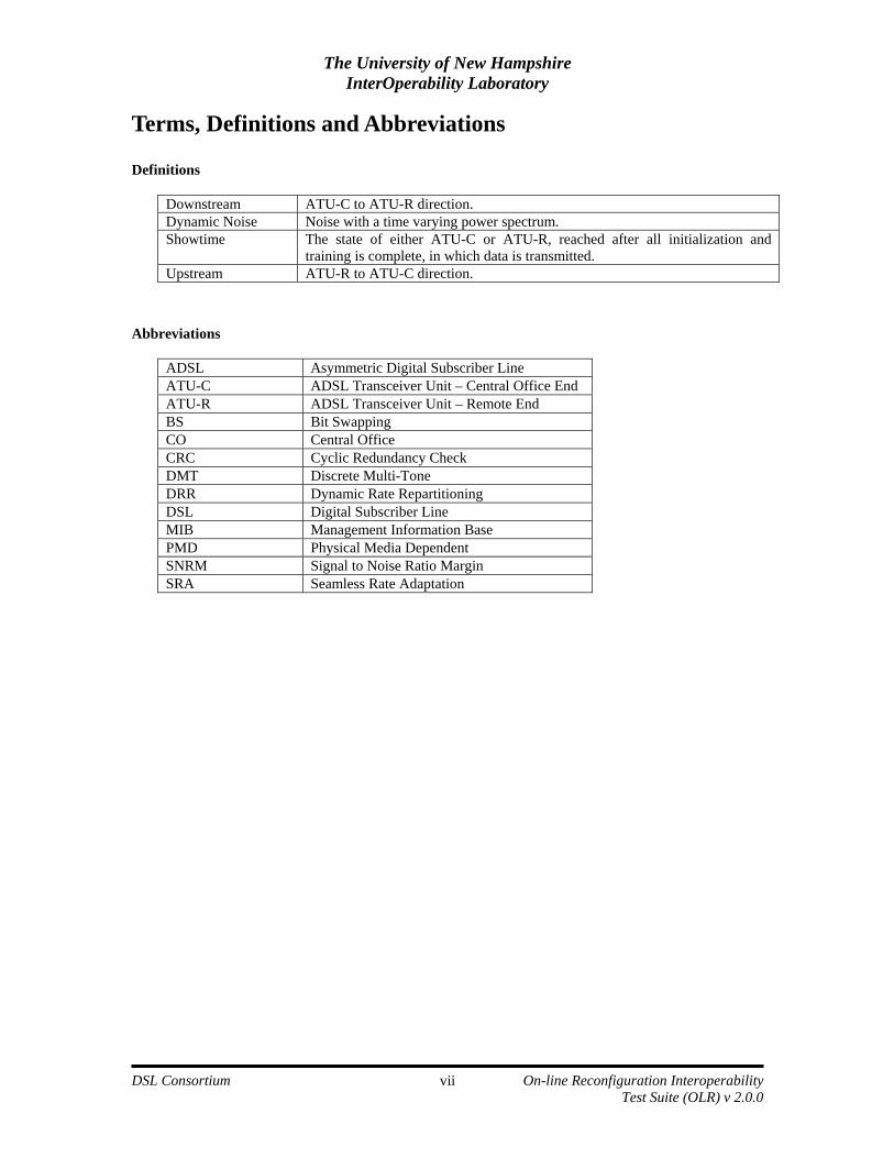
Downstream ATU-C to ATU-R direction. Dynamic Noise Noise with a time varying power spectrum. Showtime The state of either ATU-C or ATU-R, reached after all initialization and
training is complete, in which data is transmitted. Upstream ATU-R to ATU-C direction.
Abbreviations
ADSL Asymmetric Digital Subscriber Line ATU-C ADSL Transceiver Unit – Central Office End ATU-R ADSL Transceiver Unit – Remote End BS Bit Swapping CO Central Office CRC Cyclic Redundancy Check DMT Discrete Multi-Tone DRR Dynamic Rate Repartitioning DSL Digital Subscriber Line MIB Management Information Base PMD Physical Media Dependent SNRM Signal to Noise Ratio Margin SRA Seamless Rate Adaptation
The University of New Hampshire InterOperability Laboratory
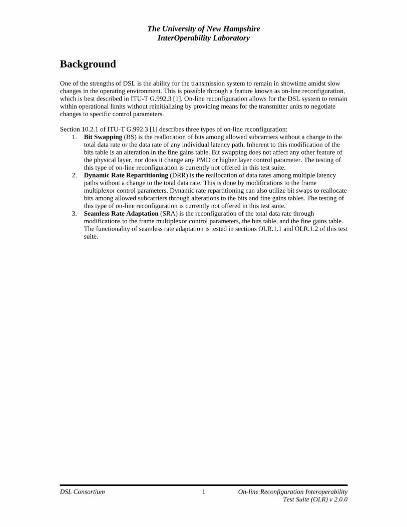
Background One of the strengths of DSL is the ability for the transmission system to remain in showtime amidst slow changes in the operating environment. This is possible through a feature known as on-line reconfiguration, which is best described in ITU-T G.992.3 [1]. On-line reconfiguration allows for the DSL system to remain within operational limits without reinitializing by providing means for the transmitter units to negotiate changes to specific control parameters. Section 10.2.1 of ITU-T G.992.3 [1] describes three types of on-line reconfiguration:
1. Bit Swapping (BS) is the reallocation of bits among allowed subcarriers without a change to the total data rate or the data rate of any individual latency path. Inherent to this modification of the bits table is an alteration in the fine gains table. Bit swapping does not affect any other feature of the physical layer, nor does it change any PMD or higher layer control parameter. The testing of this type of on-line reconfiguration is currently not offered in this test suite.
2. Dynamic Rate Repartitioning (DRR) is the reallocation of data rates among multiple latency paths without a change to the total data rate. This is done by modifications to the frame multiplexor control parameters. Dynamic rate repartitioning can also utilize bit swaps to reallocate bits among allowed subcarriers through alterations to the bits and fine gains tables. The testing of this type of on-line reconfiguration is currently not offered in this test suite.
3. Seamless Rate Adaptation (SRA) is the reconfiguration of the total data rate through modifications to the frame multiplexor control parameters, the bits table, and the fine gains table. The functionality of seamless rate adaptation is tested in sections OLR.1.1 and OLR.1.2 of this test suite.
The University of New Hampshire InterOperability Laboratory
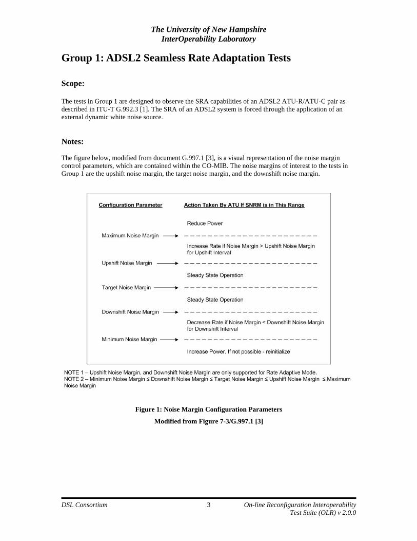
Group 1: ADSL2 Seamless Rate Adaptation Tests Scope: The tests in Group 1 are designed to observe the SRA capabilities of an ADSL2 ATU-R/ATU-C pair as described in ITU-T G.992.3 [1]. The SRA of an ADSL2 system is forced through the application of an external dynamic white noise source. Notes: The figure below, modified from document G.997.1 [3], is a visual representation of the noise margin control parameters, which are contained within the CO-MIB. The noise margins of interest to the tests in Group 1 are the upshift noise margin, the target noise margin, and the downshift noise margin.
Figure 1: Noise Margin Configuration Parameters
Modified from Figure 7-3/G.997.1 [3]
The University of New Hampshire InterOperability Laboratory
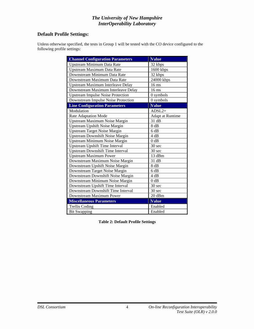
Default Profile Settings: Unless otherwise specified, the tests in Group 1 will be tested with the CO device configured to the following profile settings:
Channel Configuration Parameters Value Upstream Minimum Data Rate 32 kbps Upstream Maximum Data Rate 1600 kbps Downstream Minimum Data Rate 32 kbps Downstream Maximum Data Rate 24000 kbps Upstream Maximum Interleave Delay 16 ms Downstream Maximum Interleave Delay 16 ms Upstream Impulse Noise Protection 0 symbols Downstream Impulse Noise Protection 0 symbols Line Configuration Parameters Value Modulation ADSL2+ Rate Adaptation Mode Adapt at Runtime Upstream Maximum Noise Margin 31 dB Upstream Upshift Noise Margin 8 dB Upstream Target Noise Margin 6 dB Upstream Downshift Noise Margin 4 dB Upstream Minimum Noise Margin 0 dB Upstream Upshift Time Interval 30 sec Upstream Downshift Time Interval 30 sec Upstream Maximum Power 13 dBm Downstream Maximum Noise Margin 31 dB Downstream Upshift Noise Margin 8 dB Downstream Target Noise Margin 6 dB Downstream Downshift Noise Margin 4 dB Downstream Minimum Noise Margin 0 dB Downstream Upshift Time Interval 30 sec Downstream Downshift Time Interval 30 sec Downstream Maximum Power 20 dBm Miscellaneous Parameters Value Trellis Coding Enabled Bit Swapping Enabled
Table 2: Default Profile Settings
The University of New Hampshire InterOperability Laboratory
Test OLR.1.1: SRA Functionality in the Presence of Increasing Noise Purpose: The purpose of this test is to observe the SRA functionality of an ADSL2 ATU-R/ATU-C pair in the presence of an increasing noise environment. References:
• ATU-R • ATU-C • Line simulator(s) capable of simulating the loop type and lengths as necessary. • Impairment generator capable of simulating the dynamic white noise. • Coupling circuits.
Last Modification: May 30, 2006 Test Setup:
• Test Setup 1 Discussion: There are three rate adaptation modes that can be selected during the initialization process. The first mode, manual, allows for the upstream and downstream data rates to be user specified. However, both the ATU-C and ATU-R must achieve a noise margin equal to or greater than its corresponding target noise margin at the specified data rate. If this requirement is not met, initialization will fail. The second rate adaptation mode, rate adaptive at initialization, allows for the ATU-C and ATU-R to determine the data rates at which they will operate based on loop conditions. This is provided that the system stays within rate, noise margin and other configured parameters. Following initialization, the upstream and downstream data rates remain fixed. The third rate adaptation mode, dynamic rate adaptation (synonymous with SRA), is similar to rate adaptation at initialization with the exception that the upstream or downstream rate of the system may vary after initialization. Both the upstream and downstream data rate, however, must remain within the bounds of its associated minimum and maximum configuration parameters. The event of a data rate modification is triggered based on the SNRM of the line. Document ITU-T G.997.1 [3] defines five noise margin control parameters for each ATU of an ADSL2 system. A visual representation of these noise margins is shown in Figure 1. Since this test is designed to observe SRA in an increasing noise environment, the two noise margins that are of particular interest to this test are the target noise margin and the downshift noise margin. The target noise margin is the signal to noise ratio margin with respect to the bit error rate requirement at which each ATU attempts to initialize. Therefore, during the initialization process, the ATU-C receiver must achieve or exceed an SNRM as defined by the upstream target noise margin. Similarly, the ATU-R receiver must achieve or exceed an SNRM as defined by the downstream target noise margin during the initialization process. The downshift noise margin specifies a threshold which serves as a precondition for SRA, as does the downshift time interval. If the power of noise on the loop increases such that the SNRM in either direction falls below its corresponding downshift noise margin for a time period greater than the downshift time interval, SRA should be employed. The result should be a decrease in the data rate in the affected direction and an SNRM closer to the target noise margin. By injecting a simulated ADSL2 loop with white noise and steadily increasing it, the SNRM in both the upstream frequency band and the downstream frequency band will decrease. This decrease in SNRM is closely observed by periodically collecting transmission information of the ADSL2 system through the CO device. If the SNRM in either direction decreases beyond the threshold of its corresponding downshift noise margin, the ATU-C/ATU-R pair should successfully negotiate SRA by decreasing the rate in the affected direction without the link leaving showtime.
The University of New Hampshire InterOperability Laboratory
1. Configure the ATU-C port to be used for testing to profile settings outlined in Table 2. 2. Create the physical link between the ATU-C and the ATU-R by simulating a loop length of 1 kft
with the loop simulator. 3. Administratively disable the ATU-C port. 4. Generate white noise at a level of –140 dBm/Hz. Inject noise on both the upstream and
downstream direction of the loop. 5. Administratively enable the ATU-C port. 6. Wait for 2 minutes. 7. Collect transmission information from the ATU-C. Record this information along with whether or
not the ATU-R retrained during this 2-minute period. 8. Increase the level of white noise by 1 dB. 9. Repeat steps 6 through 8 until level of white noise reaches –100 dBm/Hz. 10. Administratively disable the ATU-C port. 11. Repeat Steps 2 through 10 with a loop length of 3, 6, 9, and 12 kft.
Observable Results:
1. As the power of the injected white noise on the simulated loop increases, the SNRM in both the upstream and downstream direction should decrease.
2. If the SNRM in either the upstream or downstream direction decreases to beyond its corresponding downshift noise margin, there should be a corresponding decrease in data rate. This decrease in data rate should also cause the corresponding SNRM to increase.
Possible Problems:
1. The ADSL2 link is not in showtime during step #7 of the procedure, thus making it impossible to collect transmission information.
The University of New Hampshire InterOperability Laboratory
Test OLR.1.2: SRA Functionality in the Presence of Decreasing Noise Purpose: The purpose of this test is to observe the SRA functionality of an ADSL2 ATU-R/ATU-C pair in the presence of a decreasing noise environment. References:
• ATU-R • ATU-C • Line simulator(s) capable of simulating the loop type and lengths as necessary. • Impairment generator capable of simulating the dynamic white noise. • Coupling circuits.
Last Modification: May 30, 2006 Test Setup:
• Test Setup 1 Discussion: There are three rate adaptation modes that can be selected during the initialization process. The first mode, manual, allows for the upstream and downstream data rates to be user specified. However, both the ATU-C and ATU-R must achieve a noise margin equal to or greater than its corresponding target noise margin at the specified data rate. If this requirement is not met, initialization will fail. The second rate adaptation mode, rate adaptive at initialization, allows for the ATU-C and ATU-R to determine the data rates at which they will operate based on loop conditions. This is provided that the system stays within rate, noise margin and other configured parameters. Following initialization, the upstream and downstream data rates remain fixed. The third rate adaptation mode, dynamic rate adaptation (synonymous with SRA), is similar to rate adaptation at initialization with the exception that the upstream or downstream rate of the system may vary after initialization. Both the upstream and downstream data rate, however, must remain within the bounds of its associated minimum and maximum configuration parameters. The event of a data rate modification is triggered based on the SNRM of the line. Document ITU-T G.997.1 [3] defines five noise margin control parameters for each ATU of an ADSL2 system. A graphical representation of these noise margins is shown in Figure 1. Since this test is designed to observe SRA in a decreasing noise environment, the two noise margins that are of particular interest to this test are the target noise margin and the upshift noise margin. The target noise margin is the signal to noise ratio margin with respect to the bit error rate requirement at which each ATU attempts to initialize. Therefore, during the initialization process, the ATU-C receiver must achieve or exceed an SNRM as defined by the upstream target noise margin. Similarly, the ATU-R receiver must achieve or exceed an SNRM as defined by the downstream target noise margin during the initialization process. The upshift noise margin specifies a threshold which serves as a precondition for SRA, as does the upshift time interval. If the power of noise on the loop decreases such that the SNRM in either direction rises above its corresponding upshift noise margin for a time period greater than the upshift time interval, SRA should be employed. The result should be an increase in the data rate in the affected direction and an SNRM closer to the target noise margin. By injecting a simulated ADSL2 loop with white noise and steadily decreasing it, the SNRM in both the upstream frequency band and the downstream frequency band will increase. This increase in SNRM is closely observed by periodically collecting transmission information of the ADSL2 system through the CO device. If the SNRM in either direction increases beyond the threshold of its corresponding upshift noise margin, the ATU-C/ATU-R pair should successfully negotiate SRA by increasing the rate in the affected direction without the link leaving showtime.
The University of New Hampshire InterOperability Laboratory
1. Configure the ATU-C port to be used for testing to profile settings outlined in Table 2. 2. Create the physical link between the ATU-C and the ATU-R by simulating a loop length of 1 kft
with the loop simulator. 3. Administratively disable the ATU-C port. 4. Generate white noise at a level of –100 dBm/Hz. Inject noise on both the upstream and
downstream direction of the loop. 5. Administratively enable the ATU-C port. 6. Wait for 2 minutes. 7. Collect transmission information from the ATU-C. Record this information along with whether or
not the ATU-R retrained during this 2-minute period. 8. Decrease the level of white noise by 1 dB. 9. Repeat steps 6 through 8 until level of white noise reaches –140 dBm/Hz. 10. Administratively disable the ATU-C port. 11. Repeat Steps 2 through 10 with a loop length of 3, 6, 9, and 12 kft.
Observable Results:
1. As the power of the injected white noise on the simulated loop decreases, the SNRM in both the upstream and downstream direction should increase.
2. If the SNRM in either the upstream or downstream direction increases to beyond its corresponding upshift noise margin, there should be a corresponding increase in data rate. This increase in data rate should also cause the corresponding SNRM to decrease.
Possible Problems:
1. The ADSL2 link is not in showtime during step #7 of the procedure, thus making it impossible to collect transmission information.
The University of New Hampshire InterOperability Laboratory
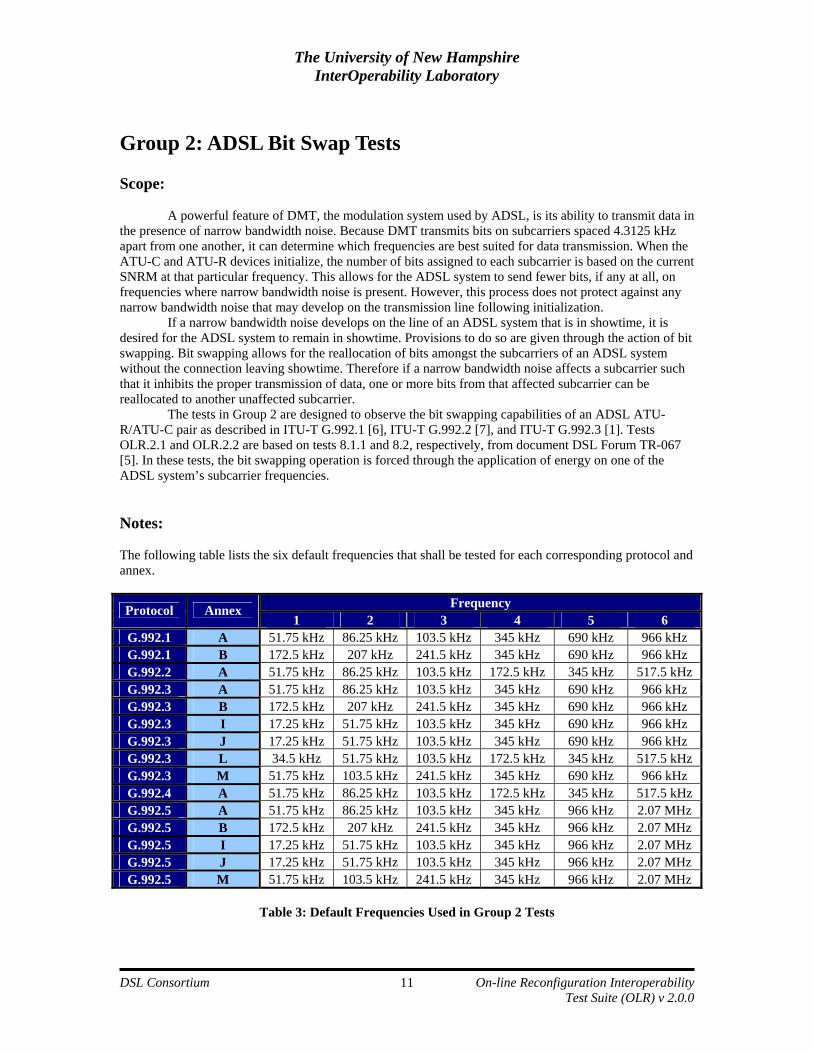
A powerful feature of DMT, the modulation system used by ADSL, is its ability to transmit data in the presence of narrow bandwidth noise. Because DMT transmits bits on subcarriers spaced 4.3125 kHz apart from one another, it can determine which frequencies are best suited for data transmission. When the ATU-C and ATU-R devices initialize, the number of bits assigned to each subcarrier is based on the current SNRM at that particular frequency. This allows for the ADSL system to send fewer bits, if any at all, on frequencies where narrow bandwidth noise is present. However, this process does not protect against any narrow bandwidth noise that may develop on the transmission line following initialization.
If a narrow bandwidth noise develops on the line of an ADSL system that is in showtime, it is desired for the ADSL system to remain in showtime. Provisions to do so are given through the action of bit swapping. Bit swapping allows for the reallocation of bits amongst the subcarriers of an ADSL system without the connection leaving showtime. Therefore if a narrow bandwidth noise affects a subcarrier such that it inhibits the proper transmission of data, one or more bits from that affected subcarrier can be reallocated to another unaffected subcarrier.
The tests in Group 2 are designed to observe the bit swapping capabilities of an ADSL ATU-R/ATU-C pair as described in ITU-T G.992.1 [6], ITU-T G.992.2 [7], and ITU-T G.992.3 [1]. Tests OLR.2.1 and OLR.2.2 are based on tests 8.1.1 and 8.2, respectively, from document DSL Forum TR-067 [5]. In these tests, the bit swapping operation is forced through the application of energy on one of the ADSL system’s subcarrier frequencies. Notes: The following table lists the six default frequencies that shall be tested for each corresponding protocol and annex.
Test OLR.2.1: Bit Swap Functionality Test Purpose: The purpose of this test is to observe the basic bit swap functionality of an ADSL ATU-R/ATU-C pair by injecting an interfering tone at one of the system’s subcarrier frequencies. References:
• ATU-R • ATU-C • Line simulator(s) capable of simulating a straight loop of 3 kft 26 AWG. • Impairment generator capable of simulating the specified level of white noise. • Signal generator capable of creating a single tone with an amplitude range of –75 dBm to –50
dBm at the frequencies given in Table 3. • Coupling circuits.
Last Modification: August 14, 2006 Test Setup:
• Test Setup 1 Discussion:
Test OLR.2.1 is based on test 8.1.1 of DSL Forum TR-067 [5]. To observe the basic functionality of an ADSL system, a single tone is injected onto an active ADSL transmission system. The power level of this tone is then increased, thereby causing the SNRM of the corresponding subcarrier to decrease. Once the subcarrier is sufficiently affected by the injected tone, bits should be reallocated into another subcarrier. The power level of the injected tone is then decreased and removed to observe if bits are reallocated back into the targeted tone. If the ADSL system leaves showtime at any point over the duration of the test, the test ends and the dropped connection is noted in the test report. Procedure:
1. Configure the ATU-C port to be used for testing with a profile with SRA disabled. 2. Create the physical link between the ATU-C and the ATU-R by simulating a loop length of 3 kft
with the loop simulator. 3. Administratively disable the ATU-C port. 4. Generate white noise at a level of –140 dBm/Hz. Inject noise on both the upstream and
downstream direction of the loop. 5. Administratively enable the ATU-C port. 6. Wait for 2 minutes to allow for initialization and settling of bit swaps. 7. Collect transmission information from the ATU-C. 8. Record the bit allocation table from the ATU-C. 9. Inject a –75 dBm tone on the ATU-C side of the loop simulator as specified by frequency #1 in
Table 3. 10. Wait 2 minutes for the settling of bit swaps. 11. Record the bit allocation table from the ATU-C. 12. Increase the power level of the tone by 5 dB 13. Repeat steps 10 through 12, until the injected tone reaches –50 dBm. 14. Wait 2 minutes for the settling of bit swaps. 15. Record the bit allocation table from the ATU-C.
The University of New Hampshire InterOperability Laboratory
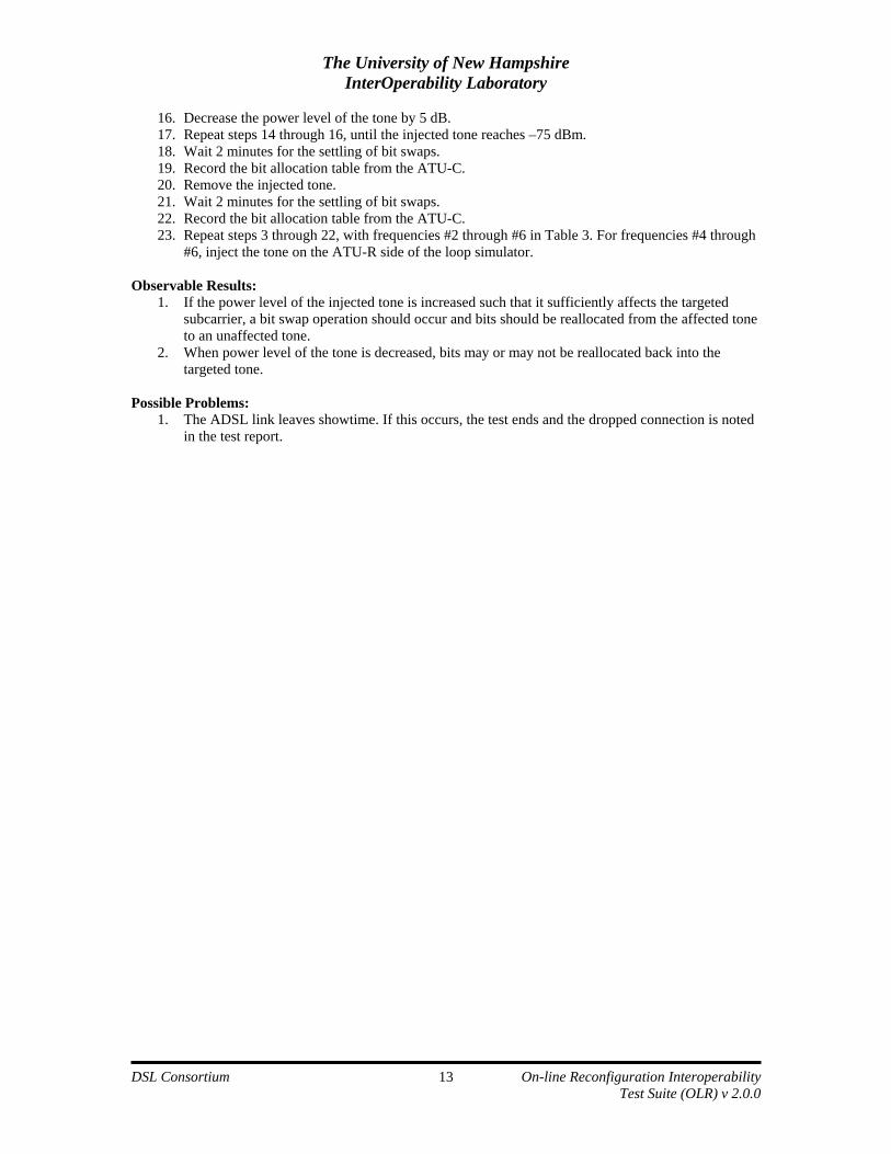
16. Decrease the power level of the tone by 5 dB. 17. Repeat steps 14 through 16, until the injected tone reaches –75 dBm. 18. Wait 2 minutes for the settling of bit swaps. 19. Record the bit allocation table from the ATU-C. 20. Remove the injected tone. 21. Wait 2 minutes for the settling of bit swaps. 22. Record the bit allocation table from the ATU-C. 23. Repeat steps 3 through 22, with frequencies #2 through #6 in Table 3. For frequencies #4 through
#6, inject the tone on the ATU-R side of the loop simulator. Observable Results:
1. If the power level of the injected tone is increased such that it sufficiently affects the targeted subcarrier, a bit swap operation should occur and bits should be reallocated from the affected tone to an unaffected tone.
2. When power level of the tone is decreased, bits may or may not be reallocated back into the targeted tone.
Possible Problems:
1. The ADSL link leaves showtime. If this occurs, the test ends and the dropped connection is noted in the test report.
The University of New Hampshire InterOperability Laboratory
Test OLR.2.2: Bit Swap Stress Test Purpose: The purpose of this test is to observe the functionality of bit swapping between an ATU-C/ATU-C pair in the presence of a stressful narrow bandwidth noise. References:
• ATU-R • ATU-C • Line simulator(s) capable of simulating the loop type and lengths as necessary. • Impairment generator capable of simulating the specified level of white noise. • Signal generator capable of creating a single tone with an amplitude of -50 dBm at the frequencies
given by Table 3. • Coupling circuits. • A device capable of generating, receiving, and analyzing network traffic. This device must be
capable of terminating the primary non-DSL network connections on both the ATU-C and the ATU-R and transmitting a fixed number of frames. o If the ATU-R is an internal device such as a PCI card in a PC or a USB modem, loop back at
the ATU-R may be used to perform this test. Alternatively, the PC hosting the ATU-R may be configured to route network traffic through an available Ethernet interface.
o The ATU-R must support bridging of Ethernet to ATM using LLC/SNAP encapsulation as defined in RFC 2684 [9].
Last Modification: August 14, 2006 Test Setup:
• Test Setup 2 Discussion:
Test OLR.2.2 is based on test 8.2 of DSL Forum TR-067 [5]. This test is considered to be a stress test as the –50 dBm interfering tone injected on the ADSL line is much more powerful than the initially injected tone in test OLR.2.1. To verify the ADSL system properly handles this powerful sudden narrow bandwidth noise, network traffic is passed over the ADSL connection prior to the injection of the tone. For the purpose of this test, the frame rate used for each test case should be 90% of the maximum frame rate supported by the ADSL connection rate. Annex D of the UNH-IOL DSL Consortium APLIT Test Suite v3.2.1 [8] defines the calculations necessary to determine the maximum frame rate supported by the DSL connection rate, based upon this total frame size.
Immediately following the injection of the –50 dBm tone at the designated frequency, CRC errors in either the upstream or downstream direction could occur due to the sudden application of narrow bandwidth noise. However, if the ATU-C/ATU-R pair properly handle the noise source, any initial CRC errors should subside with time. Additionally, the ADSL line should not leave showtime and bitswap operations should occur. If the ADSL system leaves showtime at any point over the duration of the test, the test ends and the dropped connection is noted in the test report. Procedure:
1. Configure the ATU-C port to be used for testing with a profile with SRA disabled.
The University of New Hampshire InterOperability Laboratory
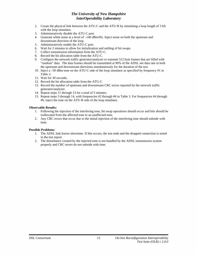
2. Create the physical link between the ATU-C and the ATU-R by simulating a loop length of 3 kft with the loop simulator.
3. Administratively disable the ATU-C port. 4. Generate white noise at a level of –140 dBm/Hz. Inject noise on both the upstream and
downstream direction of the loop. 5. Administratively enable the ATU-C port. 6. Wait for 2 minutes to allow for initialization and settling of bit swaps. 7. Collect transmission information from the ATU-C. 8. Record the bit allocation table from the ATU-C. 9. Configure the network traffic generator/analyzer to transmit 512 byte frames that are filled with
“random” data. The data frames should be transmitted at 90% of the ADSL net data rate in both the upstream and downstream directions simultaneously for the duration of the test.
10. Inject a –50 dBm tone on the ATU-C side of the loop simulator as specified by frequency #1 in Table 3.
11. Wait for 30 seconds. 12. Record the bit allocation table from the ATU-C. 13. Record the number of upstream and downstream CRC errors reported by the network traffic
generator/analyzer. 14. Repeat steps 11 through 13 for a total of 5 minutes. 15. Repeat steps 3 through 14, with frequencies #2 through #6 in Table 3. For frequencies #4 through
#6, inject the tone on the ATU-R side of the loop simulator. Observable Results:
1. Following the injection of the interfering tone, bit swap operations should occur and bits should be reallocated from the affected tone to an unaffected tone.
2. Any CRC errors that occur due to the initial injection of the interfering tone should subside with time.
Possible Problems:
1. The ADSL link leaves showtime. If this occurs, the test ends and the dropped connection is noted in the test report.
2. The disturbance created by the injected tone is not handled by the ADSL transmission system properly and CRC errors do not subside with time.
The University of New Hampshire InterOperability Laboratory
Annex A: Results Grids Group 1 Results Grid Legend
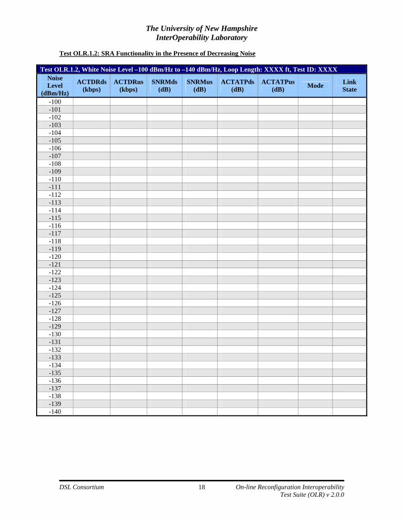
Test OLR.1.#, White Noise Level –XXX dBm/Hz to –XXX dBm/Hz, Loop Length: XXXX ft, Test ID: XXXX Noise Level
(dBm/Hz)
ACTDRds (kbps)
ACTDRus (kbps)
SNRMds (dB)
SNRMus (dB)
ACTATPds(dB)
ACTATPus (dB) Mode Link
State
Where:
• Noise Level = White noise power level in dBm/Hz. • ACTDRds = Downstream Actual Data Rate in kbps. • ACTDRus = Upstream Actual Data Rate in kbps. • SNRMds = Downstream Signal to Noise Ratio Margin in dB. • SNRMus = Upstream Signal to Noise Ratio Margin in dB. • ACTATPds = Downstream Actual Aggregate Transmit Power in dB. • ACTATPus = Upstream Actual Aggregate Transmit Power in dB. • Mode = ANSI (ANSI T1.413-1998), DMT (ITU-T G.992.1 Annex A/B), LITE (ITU-T G.992.2),
A2 (ITU-T G.992.3 Annex A/B), A2 L (ITU-T G.992.3 Annex L) or A2+ (ITU-T G.992.5). • Link State = Indicates the link state of the DSL system since the previous collection of
transmission information. INIT = the system initialized, RE-INIT = the system reinitialized, IS = the system remained in service for the duration of time.
The University of New Hampshire InterOperability Laboratory
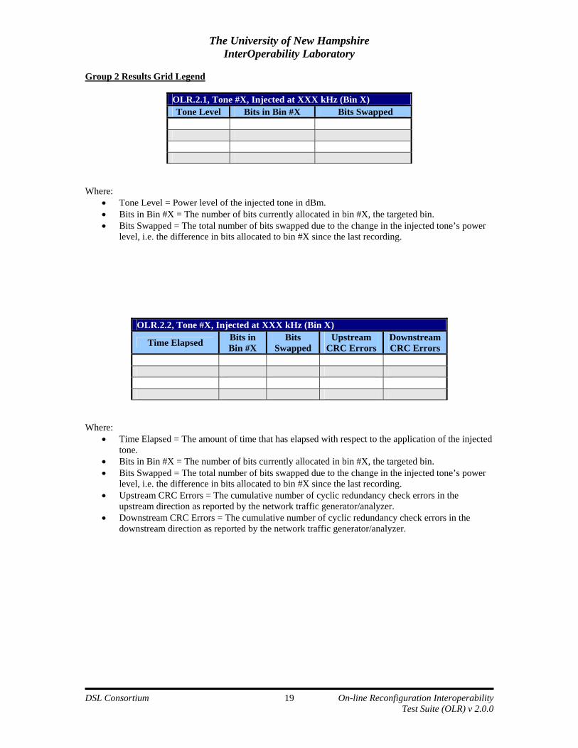
OLR.2.1, Tone #X, Injected at XXX kHz (Bin X) Tone Level Bits in Bin #X Bits Swapped
Where:
• Tone Level = Power level of the injected tone in dBm. • Bits in Bin #X = The number of bits currently allocated in bin #X, the targeted bin. • Bits Swapped = The total number of bits swapped due to the change in the injected tone’s power
level, i.e. the difference in bits allocated to bin #X since the last recording.
OLR.2.2, Tone #X, Injected at XXX kHz (Bin X)
Time Elapsed Bits in Bin #X
Bits Swapped
Upstream CRC Errors
Downstream CRC Errors
Where:
• Time Elapsed = The amount of time that has elapsed with respect to the application of the injected tone.
• Bits in Bin #X = The number of bits currently allocated in bin #X, the targeted bin. • Bits Swapped = The total number of bits swapped due to the change in the injected tone’s power
level, i.e. the difference in bits allocated to bin #X since the last recording. • Upstream CRC Errors = The cumulative number of cyclic redundancy check errors in the
upstream direction as reported by the network traffic generator/analyzer. • Downstream CRC Errors = The cumulative number of cyclic redundancy check errors in the
downstream direction as reported by the network traffic generator/analyzer.
The University of New Hampshire InterOperability Laboratory
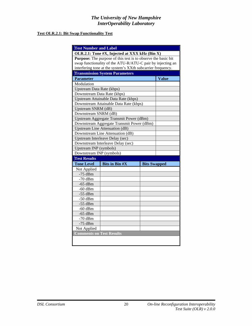
Test Number and Label OLR.2.1: Tone #X, Injected at XXX kHz (Bin X) Purpose: The purpose of this test is to observe the basic bit swap functionality of the ATU-R/ATU-C pair by injecting an interfering tone at the system’s XXth subcarrier frequency. Transmission System Parameters Parameter Value Modulation Upstream Data Rate (kbps) Downstream Data Rate (kbps) Upstream Attainable Data Rate (kbps) Downstream Attainable Data Rate (kbps) Upstream SNRM (dB) Downstream SNRM (dB) Upstream Aggregate Transmit Power (dBm) Downstream Aggregate Transmit Power (dBm) Upstream Line Attenuation (dB) Downstream Line Attenuation (dB) Upstream Interleave Delay (sec) Downstream Interleave Delay (sec) Upstream INP (symbols) Downstream INP (symbols) Test Results Tone Level Bits in Bin #X Bits Swapped Not Applied
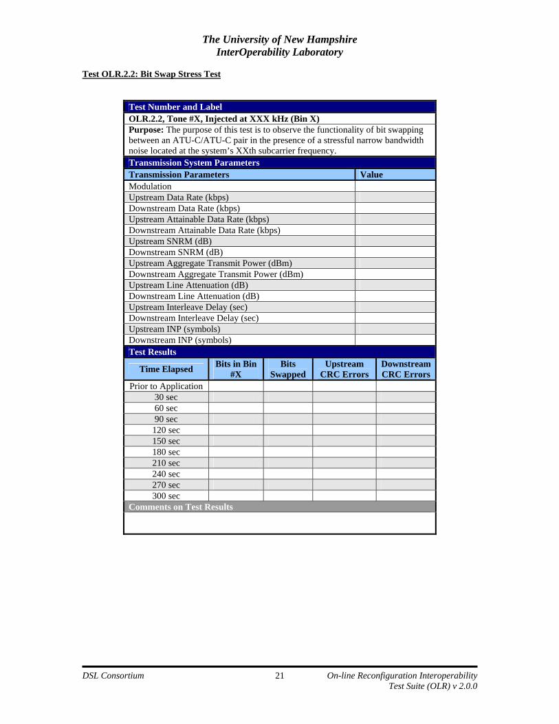
Test Number and Label OLR.2.2, Tone #X, Injected at XXX kHz (Bin X) Purpose: The purpose of this test is to observe the functionality of bit swapping between an ATU-C/ATU-C pair in the presence of a stressful narrow bandwidth noise located at the system’s XXth subcarrier frequency. Transmission System Parameters Transmission Parameters Value Modulation Upstream Data Rate (kbps) Downstream Data Rate (kbps) Upstream Attainable Data Rate (kbps) Downstream Attainable Data Rate (kbps) Upstream SNRM (dB) Downstream SNRM (dB) Upstream Aggregate Transmit Power (dBm) Downstream Aggregate Transmit Power (dBm) Upstream Line Attenuation (dB) Downstream Line Attenuation (dB) Upstream Interleave Delay (sec) Downstream Interleave Delay (sec) Upstream INP (symbols) Downstream INP (symbols) Test Results