Page 1
International Journal of Electronics communication and Electrical Engineering
ISSN : 2277-7040 Volume 3 Issue 1 (January 2013)
http://www.ijecee.com/ https://sites.google.com/site/ijeceejournal/
96
DSP Based Real Time implementation of AC-DC-AC
converter Using SPWM Technique
Umashankar S1, Mandar Bhalekar 1, Surabhi Chandra1,
Vijayakumar D1, Dr. Kothari D P 2
1 School of electrical engineering, VIT University, Vellore
[email protected] , [email protected] ,
[email protected] , [email protected] , 2 Director General
J B Group of Institutions Yenkapally, Moinabad, Hyderabad
[email protected]
ABSTRACT - In most of the drives applications, variable speed
concept is achieved by using a back-to-back two level frequency
converters. Firstly the open loop system model of ac-dc-ac converter is
designed, simulated and realized in SIMULINK. TMS 320F28335 is
used for pulse generation by SPWM technique. The problem of
controlling the induction motors driven through ac-dc-ac converters is
considered. The control objective is restricted to forcing the motor
speed to track reference signal and is done with D-Q voltage control
technique. The simulation is carried out in MATLAB/SIMULINK and
results of both simulation and actual model are compared.
Keywords : PWM, induction motor, ac-dc-ac converter, D-Q voltage
control, DSP.
1 Introduction
During the recent years in power electronics, many semiconductor switches with high
switching frequency and high power handling capability has done great improvement.
------------------------------------------------------
1 Mandar Bhalekar
Page 2
International Journal of Electronics communication and Electrical Engineering
ISSN : 2277-7040 Volume 3 Issue 1 (January 2013)
http://www.ijecee.com/ https://sites.google.com/site/ijeceejournal/
97
The other factor is the exposure of real-time computer controllers that can implement
advanced and complex control algorithms. These factors have resulted in the
development of cost-effective and grid-friendly converters. Power electronic
converters are now used in many Grid connected applications including STATCOMs,
UPFCs and active interfaces for distributed generation systems like PV or wind.
Modern power electronics plays major role in development of traction application. In
electric traction domain, used power nets are mono-phase. Due to their high capacity
to ensure flexible voltage and frequency three phase DC/AC converters are preferred
between railway nets and three phase AC motors.
Pulse Width Modulated (PWM) converters are used to overcome the problem of
dominant harmonics related with input line current rectifier circuit [1], [2]. Also, the
dynamic response of PWM rectifiers is much faster with a cut down in devices bulk
and weight [3]. The PWM converters can be operated in variable frequency mode.
There is no flexibility to adoption of different control strategies in analog circuitry
[4]. Hence, digital circuit is used. Among all PWM techniques most effective and
easy to implement method is Sine Pulse Width Modulation (SPWM). The SPWM
technique also helps to reduce heat loss in the stator winding [5].
Previous works done on induction machine speed control employs vector control or
direct control methods. But instead of going for complex calculation and data
handling speed control can achieved with D-Q voltage control explained in this paper.
This type of control is mainly confined to motor side converter only and will need
current and speed feedback.
The digital control using a digital signal processor (DSP) provides precision and
improvement in the system performance. Also, because of high speed central
processor designer can process control algorithm in real time. In this paper output of
three phase DC/AC converter is realised using digital signal processor. DSP
TMS320F28335 can be interfaced with MATLAB 2009b thereby reducing the efforts
in pulse generation. It can be programmed as per the requirement of pulses in
MATLAB 2009b [14]-[16].
Page 3
International Journal of Electronics communication and Electrical Engineering
ISSN : 2277-7040 Volume 3 Issue 1 (January 2013)
http://www.ijecee.com/ https://sites.google.com/site/ijeceejournal/
98
Most of the wind energy conversion systems consist of ac-dc-ac converters after the
induction generator so that a symmetric and pure sinusoidal voltage is available at the
output end. The WECS is modeled in MATLAB by using an asynchronous motor [8].
This PWM generation can be easily implemented in DSP interfaced with MATLAB.
This paper is organized in the following sections. The section II describes block
diagram and circuit diagram of the proposed open loop system configuration. The
open loop and closed loop simulations with results are explained in section III. IV
section explains about performance of controller designed. Hardware circuit
description and DSP implementation of proposed system is in section V and VI.
Section VII concludes the paper with references.
2 Proposed System Configuration
The basic block diagram of the open loop system is given. Basically it is a back-to-
back converter model normally used WECS. It consists of an uncontrolled converter,
IGBT based three phase inverter, speed controller and D-Q voltage controllers.
Voltage controller can be implemented with the help of MATLAB-DSP interface to
provide gate pulses to IGBTs.
Uncontrolled
rectifier
3 phase
InverterSupply LOAD
DSP
PWM
Pulses
Fig1. Block Diagram of Proposed Model
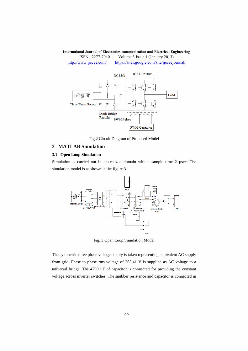
Figure 2 below shows the circuit diagram for ac-dc-ac converter normally used in
drives, tractions and other control applications. In this the main concentration is given
on the highlighted DC/AC inverter part. The pulse generation is done with digital
signal processor. IGBT switches are used to have a higher current carrying capacity
and high switching frequency. The capacitor provided gives the constant DC voltage
at the input side of the inverter.
Page 4
International Journal of Electronics communication and Electrical Engineering
ISSN : 2277-7040 Volume 3 Issue 1 (January 2013)
http://www.ijecee.com/ https://sites.google.com/site/ijeceejournal/
99
Fig.2 Circuit Diagram of Proposed Model
3 MATLAB Simulation
3.1 Open Loop Simulation
Simulation is carried out in discretized domain with a sample time 2 µsec. The
simulation model is as shown in the figure 3.
Fig. 3 Open Loop Simulation Model
The symmetric three phase voltage supply is taken representing equivalent AC supply
from grid. Phase to phase rms voltage of 265.41 V is supplied as AC voltage to a
universal bridge. The 4700 µF of capacitor is connected for providing the constant
voltage across inverter switches. The snubber resistance and capacitor is connected in
Page 5
International Journal of Electronics communication and Electrical Engineering
ISSN : 2277-7040 Volume 3 Issue 1 (January 2013)
http://www.ijecee.com/ https://sites.google.com/site/ijeceejournal/
100
parallel to the DC link capacitor for protection purpose. The DC voltage is converted
to AC output voltage by IGBT inverter.
The SPWM technique is used to trigger the switches of inverter. The reference wave
is compared with a sine wave to generate pulses at 2250 Hz. The amplitude of
reference wave decides the generated AC voltage amplitude and the frequency of
reference wave adjusts the generated AC voltage frequency. Figure 4 represents the
pulses generated by SPWM for three top switches of three legs of inverter. For bottom
switches pulses with 180 degree phase difference are provided so as to avoid short
circuit.
Fig. 4 Gate pulses by SPWM method
An induction motor is connected as a load to the inverter. Initially the load torque
applied to the motor is kept zero. After comparing with open loop real time results,
closed loop simulation can be done by applying some reduced torque than rated. It is
calculated depending on power and speed relation. The waveform quality can be
improved by LC filter at the output of the PWM inverter. For the convenience of
comparison, output voltage without LC filter is considered in this paper. The
simulation run time is fixed at 0.5 sec and results are summarized. System takes
11.042sec in real time to complete this simulation.
Page 6
International Journal of Electronics communication and Electrical Engineering
ISSN : 2277-7040 Volume 3 Issue 1 (January 2013)
http://www.ijecee.com/ https://sites.google.com/site/ijeceejournal/
101
Fig. 5 Three phase input voltage for one cycle
Fig. 6 DC link voltage
Fig. 7 Three phase AC output voltage and current
Page 7
International Journal of Electronics communication and Electrical Engineering
ISSN : 2277-7040 Volume 3 Issue 1 (January 2013)
http://www.ijecee.com/ https://sites.google.com/site/ijeceejournal/
102
Figure 5 is the input three phase voltage waveform showing phase voltages for two
cycles each of 20 ms period. The DC link voltage and AC output phase voltage and
current waveforms obtained are shown in figure 6 and 7.
Fig. 8 Speed and Torque of induction motor
Figure 8 illustrates open loop operation of motor that it is running at rated speed since
no load torque is applied.
3.2 Closed Loop Simulation
In DC/AC converters which are used in AC motor drives and for continuous AC
power supplies basically we need to have a sinusoidal AC output whose magnitude
and frequency can both be controlled.
In this paper, the voltage control of three-phase pulse width modulated voltage source
inverter has been implemented in the rotating D-Q reference frame. Block diagram for
proposed closed loop D-Q voltage control of ac-dc-ac converter is shown in figure 9.
With the control of Vd and Vq voltages using a closed loop, speed of induction motor
is controlled.
Parks transformation is performed to transform a-b-c reference frame parameters of
feedback current into d-q reference frame parameters. Speed controller generates Iqref
which is a speed or torque component of current in d-q frame. Idref (flux component
Page 8
International Journal of Electronics communication and Electrical Engineering
ISSN : 2277-7040 Volume 3 Issue 1 (January 2013)
http://www.ijecee.com/ https://sites.google.com/site/ijeceejournal/
103
of current) is manually kept fixed so that flux should not get affected while
controlling speed. This is done by using decoupling principle.
A PI controller is designed in such a way that controlled Vd and Vq are being
generated based on errors in Id and Iq respectively. The gain of PI controller is
decided based on relation between Vd, Vq and Id, Iq.
d d q
q q d
v Ri L i
v Ri L i
With the help of Parks Transformation voltages in d-q frame are transformed in a-b-c
frame as a modulating voltage signal for a discrete PWM generator. The PWM pulses
triggers IGBT switches so that inverter output voltage given to stator of induction
motor is controlled. Actual time elapsed during simulation of closed loop is 107.1593
sec.
Uncontroller
Rectifier
Three
Phase
Inverter
a-b-c to d-q
3 Phase
Induction
Motor
d-q to a-b-c
Speed
ControllerController
Discrete
PWM
Generator
Idref
Speed
Feedback
Iqref
Current
Feedback
Iq
Id
Vd-Vq
PWM
Pulses
AC
supply
DC
Link
Speed
Reference
Fig. 9 Block diagram of closed loop D-Q control
Page 9
International Journal of Electronics communication and Electrical Engineering
ISSN : 2277-7040 Volume 3 Issue 1 (January 2013)
http://www.ijecee.com/ https://sites.google.com/site/ijeceejournal/
104
Fig. 10 DC link voltage for closed loop simulation
Figure 10 shows that transients in DC link voltage are reduced in closed loop. A
disturbance in terms of step change in Idref is given at 0.3 sec of simulation. Since,
Idref is flux component of current it will change only change flux and not the speed.
Fig. 11 AC output voltage and current (R-Phase)
Figure 11 shows AC output voltage and current of inverter with very less
harmonics. It is shown for two cycles. Speed and torque observed for induction motor
is shown in figure 12 below without any distortions for zero load torque condition.
Page 10
International Journal of Electronics communication and Electrical Engineering
ISSN : 2277-7040 Volume 3 Issue 1 (January 2013)
http://www.ijecee.com/ https://sites.google.com/site/ijeceejournal/
105
Fig. 12 Speed and Torque of induction Motor
With speed as a feedback, speed component of current (Iqref) is generated through a
speed controller, which is then compared with actual value of Iq for controlled Vq.
Speed is getting settled at 155 rad/sec which is the set reference speed provided.
4 Performance of Controller
Working of controller is verified by giving a step change in Idref signal. When flux
component reference value is changed, it has no effect on speed component of
current. Iq will keep on tracking Iqref. From the figure 13 and 14, we can observe that
speed component is almost tracking speed component reference. This reveals that
speed controller is properly tuned.
Page 11
International Journal of Electronics communication and Electrical Engineering
ISSN : 2277-7040 Volume 3 Issue 1 (January 2013)
http://www.ijecee.com/ https://sites.google.com/site/ijeceejournal/
106
Fig. 13 Iq and Iqref with disturbance in Idref at 0.3 sec
Fig. 14 Speed and Torque of Induction Motor
Also from above figure, we can see that speed remains constant irrespective of
changes in flux reference. So D-Q control is achieved.
5 Hardware Circuit Description
The circuit description can be divided into two sections as the control and the power
circuit. The opto-couplers are provided as a separator between them.
The control circuit section is having three parts namely PC, DSP board and IGBT
driver. DSP is programmed to produce gate pulses by comparing a triangular carrier
wave of 2250 Hz and a sinusoidal reference wave of 50 Hz. The amplitude of
Page 12
International Journal of Electronics communication and Electrical Engineering
ISSN : 2277-7040 Volume 3 Issue 1 (January 2013)
http://www.ijecee.com/ https://sites.google.com/site/ijeceejournal/
107
reference wave decides the generated AC voltage amplitude and the frequency of
reference wave adjusts the generated AC voltage frequency. Opto-coupler amplifies
the DSP output signal to the level required to trigger IGBT and isolated DSP from
power circuit.TLP250 is used as isolator.
The power circuit section consists of four parts namely uncontrolled converter, full
bridge inverter, DC link capacitor and load. The inverter and rectifier are self content
blocks with inbuilt DC link capacitor. The waveform quality can be improved by LC
filter at the output of the PWM inverter.
6 DSP Implementation
The open loop system model is implemented in real time hardware setup using DSP-
MATLAB interface and the circuit description as specified. Using the target support
package tool of MATLAB, the DSP TMS320F28335 is connected to PC. ePWM
Module is used to generate six pulses at a time from ePWM pins of DSP. These
pulses are being fed to opto-coupler TLP 250 which boosts up the voltage level to an
extent at which IGBT switches can be triggered. The system setup is shown in the fig.
IGBT gate pulses are observed in digital signal oscilloscope.
Figure 15 represents the block diagram of the Hardware Setup. The firing pulses for
the H-bridge inverter are given from DSP board.
Three Phase
InverterAC power
output Load
PWM pulses MATLAB
Code
Composer
Studio
Uncontrolled
Rectifier
DC Link
VoltageAC power
input
Fig. 15 Block Diagram of Hardware Setup
Page 13
International Journal of Electronics communication and Electrical Engineering
ISSN : 2277-7040 Volume 3 Issue 1 (January 2013)
http://www.ijecee.com/ https://sites.google.com/site/ijeceejournal/
108
TMS320F28335 eZdsp is a floating point DSP so it is flexible for advanced
calculations. The in-built property of 12-bit ADC with a sequencer allows conversion
of multiple analog signals sequentially from DSP.
The pulse pattern can be obtained by connecting a digital oscilloscope with a DSP kit.
F28335eZdsp includes a module Event Managers which can be used for pulse
generation. Each Event Manager module contains General Purpose (GP) timers and
PWM circuits and output logic. The DSP processor has ePWM output. This DSP has
6 ePWM (Enhanced PWM) modules, which can generate the desired PWM signals
[22] [23].
MATLAB2009b has target support package library which supports the DSP
implementation [8]. The library contains ePWM blocks which are used for generating
pulse patterns. The PWM logic was developed as a simulink model. One of the
models developed in MATLAB is given below:
Fig. 16 MATLAB/Simulink model
Figure 16 shows the logic generation of bipolar PWM for three phase inverter. The
sine wave block is taken and is sampled with respect to time with a sample time of
64/80000. The sine wave is taken at a fundamental frequency of 50Hz. The amplitude
Page 14
International Journal of Electronics communication and Electrical Engineering
ISSN : 2277-7040 Volume 3 Issue 1 (January 2013)
http://www.ijecee.com/ https://sites.google.com/site/ijeceejournal/
109
and the bias value were calculated according to the count given for the timer period
value (TxPR). The bias point is half of the TxPR value and the amplitude of sine
wave is taken as 86% of the bias value. The sine wave block is converted into as per
the data type and the scaling of the output [14] [16].
The ePWM module is taken from the target support package library and in this block
the carrier wave of required frequency was generated. The counting mode was
specified as up-down counting and the compare value for the ePWM A and ePWM B
pulses were given from input port i.e. sine wave. Now whenever the compare match
occurs a pulse is generated. The timer period value can be calculated from the
following formula:
TxPR= (CPU clock frequency)/ (Desired frequency*2)
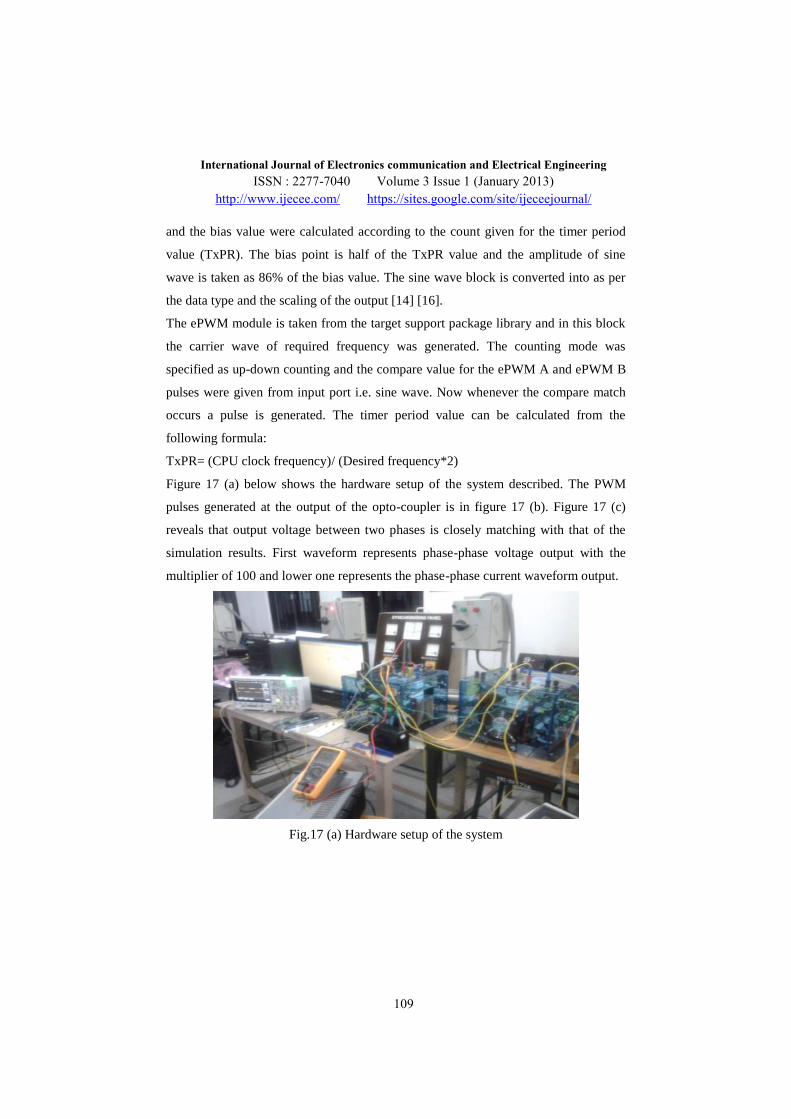
Figure 17 (a) below shows the hardware setup of the system described. The PWM
pulses generated at the output of the opto-coupler is in figure 17 (b). Figure 17 (c)
reveals that output voltage between two phases is closely matching with that of the
simulation results. First waveform represents phase-phase voltage output with the
multiplier of 100 and lower one represents the phase-phase current waveform output.
Fig.17 (a) Hardware setup of the system
Page 15
International Journal of Electronics communication and Electrical Engineering
ISSN : 2277-7040 Volume 3 Issue 1 (January 2013)
http://www.ijecee.com/ https://sites.google.com/site/ijeceejournal/
110
Fig. 17 (b) Gate Pulses from ePWM Pins of DSP for One Cycle
Fig11 (c) Phase-Phase output Voltage and Current Waveform
7 Conclusion
This paper presents the analysis and design of a digitally controlled three-phase PWM
inverter to develop more theoretical and practical knowledge for control applications.
The software optimization and Hardware installations for proposed system is
achieved. The real time simulation is done effectively using TMS320F28335 DSP at
2.55 kHz switching frequency. Speed is maintained as per the reference provided with
a simple closed loop d-q voltage control. The very close similarity between simulation
Page 16
International Journal of Electronics communication and Electrical Engineering
ISSN : 2277-7040 Volume 3 Issue 1 (January 2013)
http://www.ijecee.com/ https://sites.google.com/site/ijeceejournal/
111
and actual hardware results of output voltage waveforms illustrates the efficiency,
accuracy of PWM inverter.
Reference
[1] Madhuri Avinash Chaudhari, “Implementation of Digital Signal Processor to Control
Three-Phase Voltage-Source Inverter”, International Journal of Power System Operation
and Energy Management, ISSN (PRINT): 2231–4407, Volume-1, Issue-2, 2011.
[2] Juan Manuel Carrasco, Leopoldo Garcia Franquelo, Jan T. Bialasiewicz, “Power-Electronic
Systems for the Grid Integration of Renewable Energy Sources: A Survey”, VOL. 53, NO.
4, AUGUST 2006, IEEE TRANSACTIONS ON INDUSTRIAL ELECTRONICS.
[3] Naik Raghuram L., Jangamshetti Suresh.H, “A Critical Study of Modulation Techniques for
Three Level Diode Clamped Voltage Source Inverter for Grid Connection of WECS” 2011,
IEEE.
[4] Manjesha, Jyothi, B., "Minimization of heat in the stator windings of a 3 phase induction
motor using SPWM technique — an experimental study," Power Electronics Systems and
Applications, PESA 2009 3rd International Conference on, vol., no., pp.1-2, 20-22 May
2009.
[5] Nima Yousefpoor, Seyyed Hamid Fathi, Naeem Farokhnia, “THD Minimization Applied
Directly on the Line-to-Line Voltage of Multilevel Inverters”, IEEE TRANSACTIONS ON
INDUSTRIAL ELECTRONICS, VOL. 59, NO. 1, JANUARY 2012.
[6] F. Blaabjerg, F. Iov, Z. Chen, K. Ma, “Power Electronics and Controls for Wind Turbine
Systems”, IEEE International Conference, 2010.
[7] Kirubakaran, K., Jain, S., Nema, R.K., "DSP-Controlled PowerElectronic Interface for Fuel-
Cell-Based Distributed Generation," Power Electronics, IEEE Transactions on , vol.26,
no.12, pp.3853-3864, Dec. 2011.
[8] Pop, O., Chindris, G., Dulf, A., "Using DSP technology for true sine PWM generators for
power inverters," Electronics Technology: Meeting the Challenges of Electronics
Technology Progress, 27th International Spring Seminar on , vol.1, no. 2, pp. 141- 146, 13-
16 May 2004.
Page 17
International Journal of Electronics communication and Electrical Engineering
ISSN : 2277-7040 Volume 3 Issue 1 (January 2013)
http://www.ijecee.com/ https://sites.google.com/site/ijeceejournal/
112
[9] Guangchen Liu, Shengtie Wang, Hong Zhang and Bo Wang, “Integrated Control Strategy
of Multibrid Wind Power Generation System” 7th IEEE International Power Electronics and
Motion Control Conference - ECCE Asia, 2012.
[10] Mandar Bhalekar, Surabhi Chandra, and Umashankar S, “Closed Loop Voltage Control of
Induction Motor Drive Using AC-DC-AC PWM Converter”, International Journal of
Applied Engineering Research (IJAER), Volume 8, Number 1, 2013, pp 33-44.
[11] A. Elfadili, F. Giri, H. Ouadi, A. El Magri, L. Dugard, A. Abouloifa, “Induction Motor
Control through AC/DC/AC converters”, American control conference, Marriott Waterfront,
Baltimore, MD, USA, June 30-July 02, 2010
[12] Umashankar, S; Kothari, D P; Vijayakumar, D; Vasudevan, M, “A Novel Modeling
Approach to Real Time Digital Simulation of Induction Generator based Wind Energy
Conversion System”, International Journal of Applied Engineering Research (IJAER),
Volume 8, Number 2, 2013.
[13] Umashankar S., Vijaykumar D, Surabhi Chandra, Mandar Bhalekar and D.P. Kothari, ”
Development of a Research Platform for Power Electronic Converter Modeling using
Decoupled Analytical Method in Real Time Digital Simulation Applications”, International
Journal on Numerical and Analytical Methods in Engineering (IRENA), ISSN 2281-7026,
Vol. 1 N. 1 - February 2013.
[14] Surabhi Chandra, Mandar Bhalekar, Umashankar S and D P Kothari, “Testing and
Hardware Implementation of SPWM Inverter using TMSF28335eZDSP”, IEEE
International Conference on Circuit, Power and Computing Technologies ICCPCT-2013,
March 21-22, 2013.
[15] Mandar Bhalekar, Umashankar S, Surabhi Chandra, Vijayakumar D, and, D P Kothari,
“Development of a Research Platform for Power Electronic Converter Modeling in Real
Time Digital Simulation Applications using F28335 eZDSP”, IEEE International
Conference on Circuit, Power and Computing Technologies ICCPCT-2013, March 21-22,
2013.
[16] Surabhi Chandra, Mandar Bhalekar and Umashankar S, “DSP based hardware
implementation of Single Phase H-Bridge inverter using Bipolar SPWM technique”,
International Journal of Applied Engineering Research (IJAER), Volume 8, Number 1,
2013, pp 55-65.
[17] Umashankar S., D. Vijaykumar and D.P. Kothari, ” A Solution Method to Optimize Power
Converter Modeling for Real Time Digital Simulation Applications”, International Review
of Modeling and Simulations, ISSN 1974-9821, pp. 1969-1975, Vol. 5 N. 5 - October 2012.
Page 18
International Journal of Electronics communication and Electrical Engineering
ISSN : 2277-7040 Volume 3 Issue 1 (January 2013)
http://www.ijecee.com/ https://sites.google.com/site/ijeceejournal/
113
[18] Umashankar S., D.P. Kothari and D. Vijaykumar, ”Islanding Detection Method For VSI
Based Distributed Generation By Considering It’s Switching Frequency”, International
Review of Modeling and Simulations (IREMOS), ISSN 1974-9821, Vol. 4 N. 6 - December
2011.
[19] Samrat Saha, Kousik Sarkar, Pushpendra Singh, Umashankar S, Vijayakumar D and
Kothari D P, “Comparative Evaluation of Inverter Topologies for Wind and Solar
Applications”, INDICON 2011 Annual IEEE India Conference, Hyderabad, India,
December 16-18, 2011.
[20] Umashankar S., Ch. Bhanu Prasad, D. Vijaykumar and D.P. Kothari , ”Power Electronic
Converters and Maximum Power Point Tracking Controllers in Wind Energy Conversion
System: A Review”, pp. 1-10, International Journal of Electrical and Computer
Engineering(IJEC), Volume 3 Number 1 0974-2190 (2011).
[21] Umashankar, S; Kothari, D P; Vijayakumar, D; Vasudevan, M; Chillapalli, Bhanuprasad; ,
"Cost effective fully fed wind turbine HTS generator: An alternative to existing generators
in offshore wind farms," 2010 India International Conference on Power Electronics (IICPE),
vol., no., pp.1-6, 28-30 Jan. 2011.
[22] Texas Instruments, Code Composer StudioTM IDE. Houston, TX: Texas Instruments Inc.,
2009. Available: http://www.ti.com.Spec. Conf., Australia, 2002
[23] Texas Instruments, “TMS32081xDSP Event Manager (EV) Reference Guide,” Jun. 2007.
Available: focus.ti.com/lit/ug/spru065e/spru065e.pdf.