6-047011 X2 i Data Transfer Device Operating Instructions Data Transfer Device (DTD) Operating Instructions Note: This product is designed to be used by security and lock industry professionals. Mechanical: 3-7/8” W x 5-3/4” L x 1-1/2” D Environmental: Environment: Store Indoors. Do not get wet. Temperature Tolerance: 32º F to 120º F (0º – 49ºC) Electrical: Operating Voltage: 6V (Four AA Batteries) PC Connection: USB Port (v1.1 or v2.0) Only Software Compatibility: Hub Manager Professional version 7.3.1 (or higher) DTD Infrared Capture Software (available with Hub Manager Professional version 8.0 or higher) Firmware Version: This manual applies to firmware version 00.40 Description Hand held DATA TRANSFER DEVICE for wireless IR [infrared] transfer of data to and retrieval of the logs from LS2 Series wireless access control locksets and prox.pad plus IR wireless software managed integrated access system. In addition, the DTD has the ability to retrieve log and user data from products that support the HP Printer and can be imported to the PC using the DTD Infrared Capture Software. Data is saved to internal memory for transfer to a PC via USB connection. Powered by four AA batteries (included). Software Compatibility As mentioned above, the DTD supports two modes of operation. When using the DTD as a transfer device in DTD Mode, Hub Manager Professional Version 7.3.1 (or higher) is required. When using the DTD to retrieve HP Printer logs you must use the DTD Infrared Capture Software, which is available with Hub Manager Professional version 8.0 (or higher). The included software installation CD supports the DTD and contains the required USB drivers. You can also download the latest version of Hub Manager Professional software at www.nortekcontrol.com. Technical Support DEALERS/INSTALLERS ONLY! End users must contact the dealer/installer for support. If the unit still does not work after troubleshooting, please call the Technical Services department at 1-800-421-1587. Packing List (1) Data Transfer Device (1) DTD Operating Instructions (1) USB Cable (4) AA Batteries (already installed – see Battery Installation Section before use) (1) Hub Manager Professional Software Installation CD Important Note If you update the DTD firmware (refer to Section 5) some portions of this manual may no longer apply. Please visit our website at www.nortekcontrol.com for the latest version of this manual. FCC Statement 15.21 Information to User Any changes or modifications not expressly approved by the party responsible for compliance could void the user’s authority to operate the equipment. Specifications/Requirements:
Note: This product is designed to be usedby security and lock industry professionals.
Mechanical:3-7/8” W x 5-3/4” L x 1-1/2” D
Environmental:Environment: Store Indoors. Do not get wet.Temperature Tolerance: 32º F to 120º F (0º – 49ºC)
Electrical:Operating Voltage: 6V (Four AA Batteries)
PC Connection:USB Port (v1.1 or v2.0) Only
Software Compatibility:Hub Manager Professional version 7.3.1 (or higher)DTD Infrared Capture Software (available with HubManager Professional version 8.0 or higher)
Firmware Version:This manual applies to fi rmware version 00.40
DescriptionHand held DATA TRANSFER DEVICE for wireless IR [infrared] transfer of data to and retrieval of the logs from LS2 Series wireless access control locksets and prox.pad plus IR wireless software managed integrated access system. In addition, the DTD has the ability to retrieve log and user data from products that support the HP Printer and can be imported to the PC using the DTD Infrared Capture Software. Data is saved to internal memory for transfer to a PC via USB connection. Powered by four AA batteries (included).
Software CompatibilityAs mentioned above, the DTD supports two modes of operation. When using the DTD as a transfer device in DTD Mode, Hub Manager Professional Version 7.3.1 (or higher) is required. When using the DTD to retrieve HP Printer logs you must use the DTD Infrared Capture Software, which is available with Hub Manager Professional version 8.0 (or higher).The included software installation CD supports the DTD and contains the required USB drivers. You can also download the latest version of Hub Manager Professional software at www.nortekcontrol.com.
Technical SupportDEALERS/INSTALLERS ONLY! End users must contact the dealer/installer for support. If the unit still does not work after troubleshooting, please call the Technical Services department at 1-800-421-1587.
Packing List(1) Data Transfer Device(1) DTD Operating Instructions(1) USB Cable(4) AA Batteries (already installed – see Battery Installation Section before use)(1) Hub Manager Professional Software Installation CD
Important NoteIf you update the DTD fi rmware (refer to Section 5) some portions of this manual may no longer apply. Please visit our website at www.nortekcontrol.com for the latest version of this manual.
FCC Statement15.21 Information to User
Any changes or modifi cations not expressly approved by the party responsible for compliance could void the user’s authority to operate the equipment.
Data Transfer Device Operating Instructions Section 1: Basic Operation
Section 1: Basic Operation1.1 DTD DiagramFigure 1 below is a diagram of the DTD. The diagram illustrates the location of the Power On/Off buttons, the backlighting button and the LEDs. These are explained in detail in later sections. The Infrared (IR) Port is located at the top of the unit above the display where it says “Data Port.” Refer to Figure 2 on Page 3 for a detailed view. When transferring data to the door controller aim the Infrared (IR) Port on the DTD at the Infrared (IR) Port on the door controller.
1.2 DTD Battery InstallationPrior to using the DTD, you must remove the battery cover, which is located on the rear of the unit, and remove the red paper tab. This tab is in place so the batteries are not connected during shipping. First, remove the screw in the bottom center and remove the cover. Then remove the red tab from the battery. Replace the cover and secure it with the screw.
Figure 1: DTD Diagram
2 6-047011 X2
Data Transfer Device Operating InstructionsSection 1: Basic Operation
1.3 DTD PowerTo turn on power to the DTD press and hold the ON button. for two seconds until the DTD powers up. Note: See Section 1.2 regarding the batteries. When the DTD is fi rst powered-up the Start-up Screen is displayed, as shown below.
To turn off the DTD press the OFF button shown in the diagram. The DTD has an automatic power-off feature. After 10 minutes of inactivity the DTD turns itself off automatically to save battery life.
1.4 Display BacklightingThe DTD is equipped with display backlighting. Press the B key to turn on backlighting. The backlighting remains on for 15 seconds after the last key press to save battery life. It turns on again after pressing a key. To turn off backlighting completely press the B key again.
1.5 LED IndicatorsThe DTD uses the green and red LED’s to indicate when the device is communicating (refer to Figure 1). When the DTD is successfully communicating to the door controller, the green LED lights. If at any point you lose communications, the red LED lights. This typically means you’ve moved the DTD out of door controller’s Infrared fi eld. You have 10 seconds to re-establish communications by re-aligning the DTD’s Infrared (IR) Data Port, before the DTD times out.
6-047011 X2 3
Data Transfer Device Operating Instructions Section 2: DTD Setup
Section 2: DTD Setup2.1 Connecting the Data Transfer Device to a PC USB portTo connect the DTD to your PC USB port, use the USB cable provided with your DTD. First plug the small end (Type Mini-B) of the 6-foot USB cable into USB connector on the top of the DTD. Then plug the large end (Type A) of the 6-foot USB cable into your PC’s USB port. Figure 2 below illustrates this connection.
Figure 2: Connecting the DTD to PC USB Port
Important Note:Do not connect more than one DTD to your PC at a time.
4 6-047011 X2
Data Transfer Device Operating Instructions
2.2 Installing the USB DriversTo use the DTD you must install the USB drivers on the PC. The DTD is plug and play, so when you plug it in, your PC should recognize the new hardware and launch the Found New Hardware Wizard as shown below. Please note that this hardware wizard runs twice. Follow the same steps both times. Note: These instructions are for a typical Windows system. If you are using a different version of Windows, or these steps do not match your PC, please refer to the instructions for your system.On the fi rst screen of the wizard select “No, not this time.” then click the Next button.
After clicking the Next button, choose the option that says “Install from a list or specifi c location (Advanced)” and click the Next button.
Section 2: DTD Setup
6-047011 X2 5
Data Transfer Device Operating Instructions Section 2: DTD Setup
On the next screen select “Search for the best driver in these locations.” at the top. If you’ve already installed Hub Manager Professional onto the PC, select “Include this location in the search” and browse to the following path:C:\Program Files\IEI\HubManagerPro7\Program\Utilities\USB_Driver\FTDI_XP-2K-2003 or C:\....\FTDI_XP-2000-Vista
If you haven’t installed Hub Manager Professional, the USB drivers are also located on the CD. Choose the option “Search removable media (fl oppy, CD-ROM...).” For reference, the USB drivers are located in the following folder on the CD: E:\Driver_USB\FTDI_XP-2K-2003 or E:\Driver_USB\FTDI_XP-2000-Vista (Note: This folder path is an example; Your CD drive letter may not be E.) Click Next to continue.
Note: The path above is for Hub Manager Professional 7. If you are using a different version, browse to the folder where you installed the program.
6 6-047011 X2
Data Transfer Device Operating InstructionsSection 2: DTD Setup
Next a screen appears indicating the fi les are being copied, then you’re presented with the following screen to indicate the process is fi nished. Click on the Finish button to close the Found New Hardware Wizard. Please note that this hardware wizard runs twice due to requirement of the USB hardware manufacturer. Visit the knowledge base onwww.ftdichip.com for details. Follow the same steps both times the wizard runs.
Note: The second time through the Found New Hardware Wizard, the fi nal screen indicates the wizard has completed installing the software for: USB Serial Port.
6-047011 X2 7
Data Transfer Device Operating Instructions Section 2: DTD Setup
2.3 Determining the USB COM port numberWhen you connect the Enrollment Station to your computer’s USB port, the PC automatically assigns it a COM port number. You must then select this COM port in the software to communicate to your DTD. You can either use the automatic search feature in Hub Manager Professional or follow the instructions below to determine the COM port number. Note: These instructions are for a typical Windows XP system. If you are using a different version of Windows, or these steps do not match your PC, please refer to the instructions for your system.
1. Right click on the My Computer icon on your desktop and select properties from the drop down list.
2. When the System Properties screen opens select the Hardware tab, then click on the Device Manager button.
Note: If you do not have the My Computer icon on your desktop, you can access the System Properties by going to Control Panel. Click on the Windows Start Menu and choose Settings, then Control Panel. When the Control Panel menu opens, scroll down to System. Double-click on System to open. Follow the rest of the instructions in this section.
8 6-047011 X2
Data Transfer Device Operating Instructions
3. When the device manager list opens, expand Ports (COM & LPT) by clicking the + symbol. Under this is a list of the COM ports on your PC. Look for USB Serial Port (COMx) in the list. The COM port is shown to the right. The example below shows the DTD is assigned to COM4.Note: If you are unsure of which device it is, unplug the USB cable and the screen will refresh. Take note of which devices are in the list. Then plug the cable back in and notice which device re-appears in the list.
Important Note:If you unplug the DTD from the USB port and plug it into a different physical port on
the PC or on a USB Hub, the COM port number will remain the same.
Section 2: DTD Setup
6-047011 X2 9
Data Transfer Device Operating Instructions Section 3: DTD Mode
Section 3: DTD ModeFrom the factory, the DTD is set in DTD Mode. This mode is used to send data and retrieve transaction event logs from controllers that support two way communications.
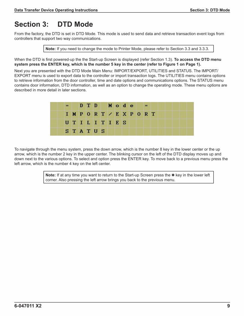
When the DTD is fi rst powered-up the the Start-up Screen is displayed (refer Section 1.3). To access the DTD menu system press the ENTER key, which is the number 5 key in the center (refer to Figure 1 on Page 1).Next you are presented with the DTD Mode Main Menu: IMPORT/EXPORT, UTILITIES and STATUS. The IMPORT/EXPORT menu is used to export data to the controller or import transaction logs. The UTILITIES menu contains options to retrieve information from the door controller, time and date options and communications options. The STATUS menu contains door information, DTD information, as well as an option to change the operating mode. These menu options are described in more detail in later sections.
To navigate through the menu system, press the down arrow, which is the number 8 key in the lower center or the up arrow, which is the number 2 key in the upper center. The blinking cursor on the left of the DTD display moves up and down next to the various options. To select and option press the ENTER key. To move back to a previous menu press the left arrow, which is the number 4 key on the left center.
Note: If you need to change the mode to Printer Mode, please refer to Section 3.3 and 3.3.3.
Note: If at any time you want to return to the Start-up Screen press the ✱ key in the lower left corner. Also pressing the left arrow brings you back to the previous menu.
10 6-047011 X2
Data Transfer Device Operating InstructionsSection 3: DTD Mode
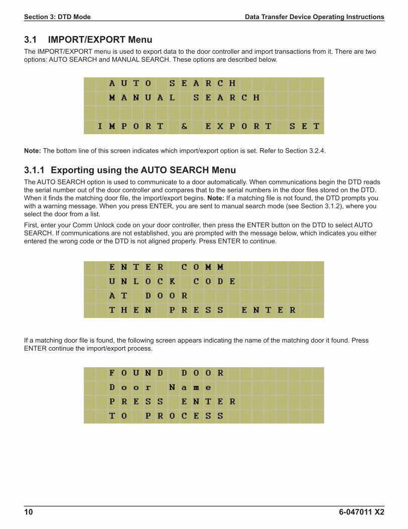
3.1 IMPORT/EXPORT MenuThe IMPORT/EXPORT menu is used to export data to the door controller and import transactions from it. There are two options: AUTO SEARCH and MANUAL SEARCH. These options are described below.
Note: The bottom line of this screen indicates which import/export option is set. Refer to Section 3.2.4.
3.1.1 Exporting using the AUTO SEARCH MenuThe AUTO SEARCH option is used to communicate to a door automatically. When communications begin the DTD reads the serial number out of the door controller and compares that to the serial numbers in the door fi les stored on the DTD. When it fi nds the matching door fi le, the import/export begins. Note: If a matching fi le is not found, the DTD prompts you with a warning message. When you press ENTER, you are sent to manual search mode (see Section 3.1.2), where you select the door from a list.First, enter your Comm Unlock code on your door controller, then press the ENTER button on the DTD to select AUTO SEARCH. If communications are not established, you are prompted with the message below, which indicates you either entered the wrong code or the DTD is not aligned properly. Press ENTER to continue.
If a matching door fi le is found, the following screen appears indicating the name of the matching door it found. Press ENTER continue the import/export process.
6-047011 X2 11
Data Transfer Device Operating Instructions Section 3: DTD Mode
When the transfer begins the following screen appears and the green LED turns on. If at any point you lose communications with the door controller, the red LED turns on. You have 10 seconds to move the DTD back into range.
When the data transfer is complete the following message appears. Press the left arrow to exit to the menu.
If a matching door fi le is not found, the following message appears. When you press ENTER you are brought to the manual search screen, which allows to choose a door from the list. Please refer to the following section discussing the MANUAL SEARCH menu.
3.1.2 Exporting using the MANUAL SEARCH MenuThe MANUAL SEARCH option is used when you are communicating to a door controller for the fi rst time or if a door is not found. When you select this option, the search screen is displayed. To navigate through the list of doors use the up and down arrows.
12 6-047011 X2
Data Transfer Device Operating InstructionsSection 3: DTD Mode
The doors are displayed as shown below. The site name is on the fi rst line and the door name is on the second line.
When you reach the door you are looking for, stop. Now enter your Comm Unlock code on your door controller and aim your DTD at the Infrared (IR) port on the door controller and press the ENTER key. If communications are not established you are prompted with the following message (either you entered the wrong code or are not aligned properly). Try again, then press ENTER to continue.
If the serial number in the export fi le you are trying to send does not match the serial number in the controller, you are prompted with a warning message. This message means one of two things: either the serial number in the door fi le you chose does not match the serial number of the door controller or this is the fi rst time you’ve attempted to communicate with the door.
If you wish to proceed, press the ENTER key to continue. When the transfer begins, the following screen appears and the green LED turns on. If at any point you lose communications with the door controller, the red LED turns on. You have 10 seconds to move the DTD back into range.
6-047011 X2 13
Data Transfer Device Operating Instructions Section 3: DTD Mode
When data transfer is complete, the message below appears. Press the up or down arrows to move through the door list.
3.2 UTILITIES MenuTo access the UTILITIES Menu press the ENTER button from the Start-up Screen. Next you a presented with three choices. Press the down arrow to move the cursor to the UTILITIES option and press the ENTER key. You have four choices in this menu, as shown below.
3.2.1 GET DOOR INFOThe GET DOOR INFO menu item is used to retrieve information from the door controller. First, enter your Comm Unlock code on the door controller. Next aim your DTD at the Infrared (IR) port on the controller and press the ENTER key. If successful, the door information is immediately displayed on the DTD screen. This information includes the door controller serial number, fi rmware part number and version, time and date.
3.2.2 SHOW DTD CLOCKThe DTD maintains the current time and date that it receives from the PC. To view the current DTD time and date, select this menu option. You can only update this time and date using the PC software.
14 6-047011 X2
Data Transfer Device Operating InstructionsSection 3: DTD Mode
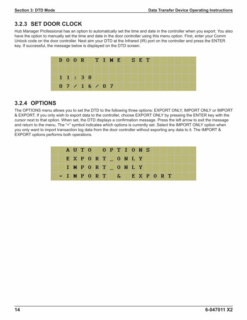
3.2.3 SET DOOR CLOCKHub Manager Professional has an option to automatically set the time and date in the controller when you export. You also have the option to manually set the time and date in the door controller using this menu option. First, enter your Comm Unlock code on the door controller. Next aim your DTD at the Infrared (IR) port on the controller and press the ENTER key. If successful, the message below is displayed on the DTD screen.
3.2.4 OPTIONSThe OPTIONS menu allows you to set the DTD to the following three options: EXPORT ONLY, IMPORT ONLY or IMPORT & EXPORT. If you only wish to export data to the controller, choose EXPORT ONLY by pressing the ENTER key with the cursor next to that option. When set, the DTD displays a confi rmation message. Press the left arrow to exit the message and return to the menu. The “=” symbol indicates which options is currently set. Select the IMPORT ONLY option when you only want to import transaction log data from the door controller without exporting any data to it. The IMPORT & EXPORT options performs both operations.
6-047011 X2 15
Data Transfer Device Operating Instructions Section 3: DTD Mode
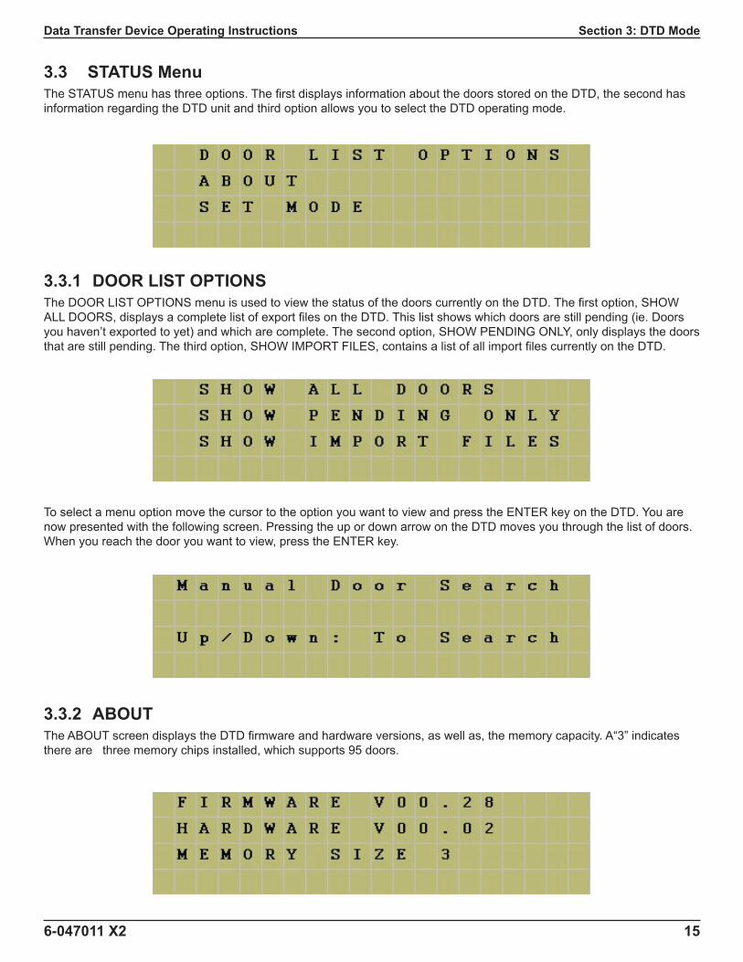
3.3 STATUS MenuThe STATUS menu has three options. The fi rst displays information about the doors stored on the DTD, the second has information regarding the DTD unit and third option allows you to select the DTD operating mode.
3.3.1 DOOR LIST OPTIONSThe DOOR LIST OPTIONS menu is used to view the status of the doors currently on the DTD. The fi rst option, SHOW ALL DOORS, displays a complete list of export fi les on the DTD. This list shows which doors are still pending (ie. Doors you haven’t exported to yet) and which are complete. The second option, SHOW PENDING ONLY, only displays the doors that are still pending. The third option, SHOW IMPORT FILES, contains a list of all import fi les currently on the DTD.
To select a menu option move the cursor to the option you want to view and press the ENTER key on the DTD. You are now presented with the following screen. Pressing the up or down arrow on the DTD moves you through the list of doors. When you reach the door you want to view, press the ENTER key.
3.3.2 ABOUTThe ABOUT screen displays the DTD fi rmware and hardware versions, as well as, the memory capacity. A“3” indicates there are three memory chips installed, which supports 95 doors.
16 6-047011 X2
Data Transfer Device Operating InstructionsSection 3: DTD Mode
3.3.3 SET MODEThis options allows you to change the operating mode of the DTD. From the factory the unit is confi gured for DTD Mode, which is indicated by the = symbol. To change to Printer Mode use the down arrow (8 key) to move the cursor next to SET PRINTER MODE, then press ENTER (5 key). Refer to Section 4, which discusses Printer Mode.
3.4 Security Risk Warning (W01)When the DTD attempts to communicate to the door controller during the import/export process, it fi rst asks the controller if program mode was entered. If program mode was entered manually on the controller, the following warning is displayed. This warning means that someone may have programmed data into the controller that doesn’t match the PC software database. When this message is displayed you can either ignore it for the time being and continue with your import/export or you can press the back arrow (4 key) to cancel the operation. To correct the situation return to the PC and choose the full export options. Please refer to the PC software documentation for complete details about performing this action.
6-047011 X2 17
Data Transfer Device Operating Instructions Section 4: Printer Mode
Section 4: Printer Mode 4.1 Set Printer ModeTo confi gure your DTD to operate in Printer Mode (from DTD Mode), go to the STATUS MENU as described in Section 3.3, then select the SET MODE option as discussed in Section 3.3.3. When the screen below appears, move the cursor down to the SET PRINTER MODE option and press ENTER. The = symbol will move down to the new setting, as shown. To return to the Start-Up Screen press the ✱ key.
4.2 Printer Mode Main MenuWhen the DTD is fi rst powered-up the the Start-up Screen is displayed (refer to Section 1.3). To access the Printer Mode menu system press the ENTER key, which is the number 5 key in the center (refer to Figure 1 on Page 1).Next you are presented with three main sub-menu selections: INFRARED CAPTURE, SEARCH DOORS and STATUS. The INFRARED CAPTURE option is used to capture data sent from the controller. The SEARCH DOORS menu option allows you to search through previously captured door data and view the information on the display. The STATUS menu contains information about the DTD, as well as an option to change the operating mode. These menu options are described in more detail in later sections.
To navigate through the menu system, press the down arrow, which is the number 8 key in the lower center or the up arrow, which is the number 2 key in the upper center. The blinking cursor on the left of the DTD display moves up and down next to the various options. To select and option press the ENTER key. To move back to a previous menu press the left arrow, which is the number 4 key on the left center.
Note: If at any time you want to return to the Start-up Screen press the ✱ key in the lower left corner. Also pressing the left arrow brings you back to the previous menu.
18 6-047011 X2
Data Transfer Device Operating InstructionsSection 4: Printer Mode
4.2.1 INFRARED CAPTURE
To start capturing data, fi rst hit the ENTER key on the INFRARED CAPTURE menu item on the main menu shown in Section 4.2. Next you are prompted with the message shown below.
To dump the transaction log or users to the DTD follow these steps:
1. Enter Program Mode on the controller keypad : 99 # master code ✱ (keypad yellow LED fl ashing slow).
2. Enter the command to dump either the transaction log or user list: ○ Enter the Log Dump command on the controller keypad: 70 # 0 # 0 # ✱ (keypad yellow LED fl ashing fast).
○ Enter the User Dump command on the controller keypad: 25 # 0 # 0 # ✱ (keypad yellow LED fl ashing fast).
3. Press ENTER on the DTD (the WAITING FOR DATA screen appears on DTD; shown below).
4. Press the ✱ key on the controller keypad (keypad LED fl ashing green and yellow)
5. When fi nished, the green LED stops fl ashing and only the yellow is fl ashing.
6. Press the ✱ key on the controller keypad to exit program mode.
Once the unit starts receiving data, the green LED turns on indicating data is being captured. If the red LED turns on, this indicates the DTD is not receiving any data. You should adjust the DTD until you see the green LED turn on. Keep in mind, however, that if the controller sent out any data prior to establishing communications, you may miss some data. Please refer to the note at the top of this page.When the DTD starts receiving, the data will scroll across the display as each line is received, similar to a paper tape. The data is stored in memory for later viewing on the DTD or to import from a PC.
Note: It’s important to note, prior to using the INFRARED CAPTURE function in Printer Mode, how this feature differs from the Import/Export function in DTD Mode. In Printer Mode, the DTD can only receive data, because the door controllers only support one-way communication. This is important because if the DTD misses any data (because it was not aligned properly or you move it out of the data stream), the controller won’t resend the data. This means there will be gaps in your data. If this occurs, dump the data a second time from the controller and be sure to keep the DTD aligned properly.
6-047011 X2 19
Data Transfer Device Operating Instructions Section 4: Printer Mode
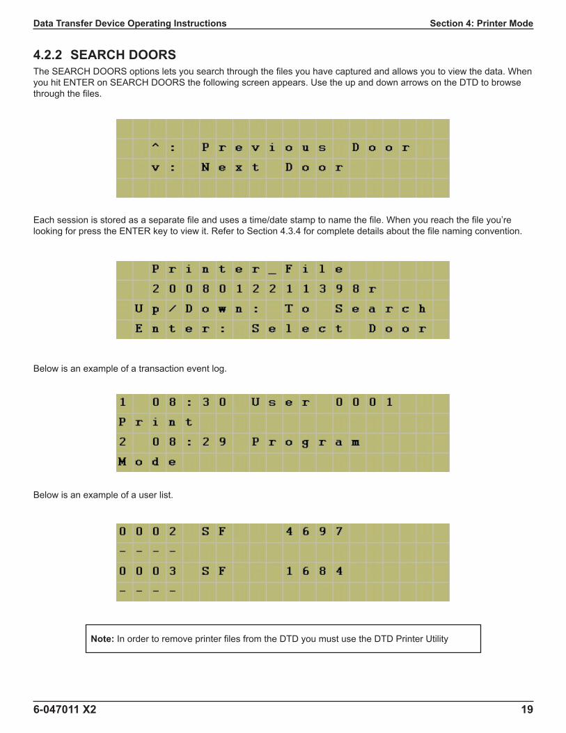
4.2.2 SEARCH DOORSThe SEARCH DOORS options lets you search through the fi les you have captured and allows you to view the data. When you hit ENTER on SEARCH DOORS the following screen appears. Use the up and down arrows on the DTD to browse through the fi les.
Each session is stored as a separate fi le and uses a time/date stamp to name the fi le. When you reach the fi le you’re looking for press the ENTER key to view it. Refer to Section 4.3.4 for complete details about the fi le naming convention.
Below is an example of a transaction event log.
Below is an example of a user list.
Note: In order to remove printer fi les from the DTD you must use the DTD Printer Utility
20 6-047011 X2
Data Transfer Device Operating InstructionsSection 4: Printer Mode
4.2.3 Status MenuThe status menu in Printer Mode contains the ABOUT option and SET MODE options. The ABOUT option contains information about the DTD, such as fi rmware part number and memory size. The SET MODE option allows you to change the DTD operating mode, as discussed in Section 4.1.
4.3 DTD Printer UtilityTo import the captured infrared log fi les from the DTD to your PC you must install the DTD Printer Utility, which is located on the Hub Manager Professional software installation CD. You are not required to install Hub Manager Professional to use this software. This is a standalone software utility used to import the transaction event logs and user data captured in printer mode. This program is not integrated with Hub Manager Professional and logs fi les can’t be viewed or imported into Hub Manager Professional.
4.3.1 Installing the DTD Printer UtilityTo install the DTD Printer Utility, fi rst insert the software installation CD. When the Autorun Setup screen opens you are presented with three choices. Choose the option that says “Install DTD Printer Utility.” Follow the on-screen instructions in the Setup Wizard to install the program.
4.3.2 Assigning the DTD COM Port
To determine the COM port Windows has assigned to your DTD, refer to Section 2.3 in this manual. Once you’ve found the COM port number, select that number in the drop down list in the DTD Printer Utility.
4.3.3 Retrieving Infrared Logs from the DTD
To retrieve the infrared log fi les from your DTD click on “Get All Printer Logs from DTD” in the DTD Printer Utility. When complete, you are prompted with a message indicating the fi les were received. The list of log fi les is shown in the left column, under Available Log Files.
Note: When you fi rst plug the DTD into your PC’s USB port, you must install the USB drivers. Refer to Section 2.2 in this manual for details about installing the USB drivers.
Note: Before attempting to retrieve log fi les, make sure your DTD is plugged into your USB port and is powered on.
6-047011 X2 21
Data Transfer Device Operating Instructions Sections 4 & 5: Updating the DTD Firmware, Printer Mode
4.3.4 Viewing and Printing Infrared Log FilesThe fi les are available for viewing directly in the DTD Printer Utility. Select the fi le you want to view in the left hand column and the data is displayed in the right hand column.The fi les are also stored as text fi les on the PC in the following folder: C:\Program Files\DTD Printer Utility\LogFiles. To access these fi les, open a text editing program, such as Windows Notepad or WordPad and browse to the folder path indicated above and open the fi le. You can also browse to the fi le through Windows Explorer.Printer File Naming ConventionPrinter fi les are named with a time/date stamp in the following format: year/month/day/hour/minute/sequence number/r. The sequence number is an easy way to differentiate two different fi les if they are created within the same minute. This number increments by 1 with each fi le. The “r” indicates that the fi le is a printer fi le.The example shown in Section 4.2.2 is 2008012211398r and this would be stored as 2008012211398r.txt on the PC. Below is a break down of the fi le name.
To erase the infrared log fi les from your DTD click on “Erase All Printer Logs from DTD” in the DTD Printer Utility. When complete, you are prompted with a message indicating the fi les were erased. This action only erases the fi les from the DTD; It does not erase them from the PC.
Section 5: Updating the DTD FirmwareThe DTD contains a feature that allows you to update the DTD fi rmware in the fi eld. As new features and enhancements are available, the new fi rmware is downloaded to your PC when you run iUpdate through Hub Manager Professional. Please refer to the PC software documentation for complete details on updating the fi rmware. If you choose to update the DTD fi rmware, remember to visit IEI’s website at www.nortekcontrol.com to download the latest revision of the DTD Operating Instructions.
Note: Before attempting to erase log fi les, make sure your DTD is plugged into your USB port and is powered on.
22 6-047011 X2
Data Transfer Device Operating InstructionsSection 6: DTD Menu Map
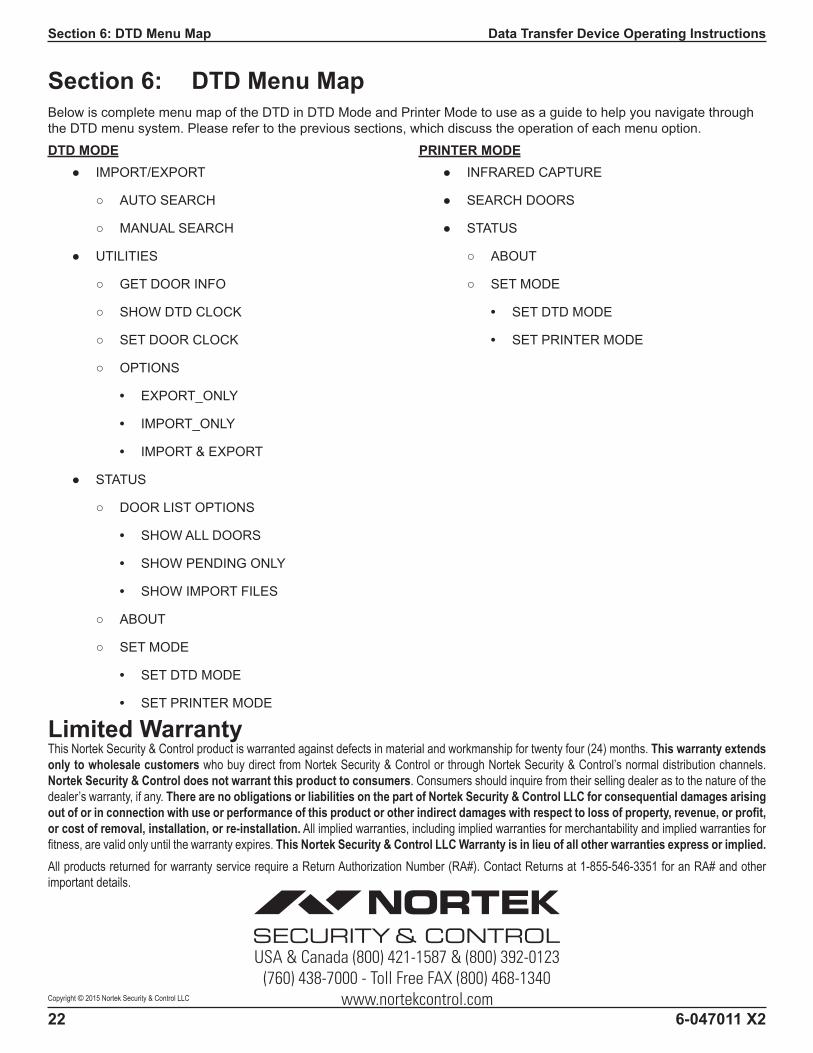
Section 6: DTD Menu MapBelow is complete menu map of the DTD in DTD Mode and Printer Mode to use as a guide to help you navigate through the DTD menu system. Please refer to the previous sections, which discuss the operation of each menu option.DTD MODE
Limited WarrantyThis Nortek Security & Control product is warranted against defects in material and workmanship for twenty four (24) months. This warranty extends only to wholesale customers who buy direct from Nortek Security & Control or through Nortek Security & Control’s normal distribution channels. Nortek Security & Control does not warrant this product to consumers. Consumers should inquire from their selling dealer as to the nature of the dealer’s warranty, if any. There are no obligations or liabilities on the part of Nortek Security & Control LLC for consequential damages arising out of or in connection with use or performance of this product or other indirect damages with respect to loss of property, revenue, or profi t, or cost of removal, installation, or re-installation. All implied warranties, including implied warranties for merchantability and implied warranties for fi tness, are valid only until the warranty expires. This Nortek Security & Control LLC Warranty is in lieu of all other warranties express or implied.All products returned for warranty service require a Return Authorization Number (RA#). Contact Returns at 1-855-546-3351 for an RA# and other important details.