96
Owner’s Manual DTZ-8R-1 NDA-31627 ISSUE 1.0 D term ® Cordless DECT

Owner’s ManualDTZ-8R-1
NDA-31627ISSUE 1.0
Dterm ®
Cordless DECT


Contents of this manual are subject to change without prior notice at the discretion of NEC
Corporation of America. This document has been prepared for the use of employees andcustomers of NEC Corporation of America and may not be reproduced without prior writtenapproval of NEC Corporation of America.
Dterm is a registered trademark of NEC Corporation.
Copyright 2017
NEC Corporation of America3929 W John Carpenter Fwy
Irving, TX 75063


Owner’s Manual i
TABLE OF CONTENTS
Chapter 1 Specifications and Safety Information
Section 1 Regulatory Information .......................................................... 1-1
1.1 Certification Label .............................................................1-1
1.2 Safety Information ............................................................1-1
1.3 Radio Frequency Interference .............................................1-1
1.4 Hearing Aid Compatibility and Volume Control ......................1-2
Section 2 Specifications ......................................................................... 1-2
2.1 General ...........................................................................1-2
2.2 Base Unit ........................................................................1-2
2.3 Handset .........................................................................1-3
2.4 Battery Charging Unit ........................................................1-3
Section 3 Battery Safety ........................................................................ 1-4
Section 4 Important Safety Instructions ................................................ 1-4
Section 5 Privacy ................................................................................... 1-6
Section 6 Important Electrical Considerations ....................................... 1-6
6.1 Electrical Safety ................................................................1-6
6.2 Range .............................................................................1-6
6.3 Telephone Line Problems ...................................................1-6
6.4 Radio Interference ............................................................1-7
6.5 More than One Cordless Telephone .....................................1-7
Chapter 2 About the Dterm Cordless DECT
Section 1 Overview ................................................................................ 2-1
Section 2 Items Included with the Dterm Cordless DECT ......................... 2-2
Section 3 Features of the Cordless Telephone ....................................... 2-3
Section 4 Dterm Controls and Functions .................................................. 2-3
ii Table of Contents
Issue 1.0
4.1 Handset ..........................................................................2-4
4.2 Base Unit .........................................................................2-5
4.3 Cordless Handset/Desk Phone Switch (Base Key Option) ........2-6
4.4 Charging Unit ...................................................................2-7
Chapter 3 Installation
Section 1 Selecting a Location ............................................................... 3-1
Section 2 Installation Precautions ......................................................... 3-1
Section 3 Connecting the Telephone Cords ............................................ 3-1
Section 4 Applying Power to the Charging Unit ...................................... 3-3
Section 5 Wall Installation ..................................................................... 3-4
5.1 Mounting the Base Directly to the Wall ................................3-4
Section 6 Attaching and Removing the Belt Clip .................................... 3-6
Section 7 Installing the Handset Batteries ............................................. 3-7
Section 8 Charging Batteries ................................................................. 3-8
8.1 Charging the Handset Batteries ..........................................3-8
Section 9 Low Battery Indicator ............................................................ 3-9
9.1 Low Battery .....................................................................3-9
9.2 Battery Status ..................................................................3-9
Section 10 Cleaning the Battery Charging Contacts ............................... 3-10
Chapter 4 Dterm Handset, Base Unit and Charging Unit
Section 1 Handset Controls .................................................................... 4-1
Chapter 5 Optional Equipment Installation
Section 1 Replacement Parts and Optional Accessories ......................... 5-1
Section 2 Installing the Optional Headset .............................................. 5-2

Owner’s Manual iii
Issue 1.0
Chapter 6 Setup and Operation
Section 1 Setting Up and Programming the DTZ-8R-1 ........................... 6-1
1.1 Programming Mode ...........................................................6-1
1.1.1 Training Mode (Entry) .................................................... 6-1
1.1.2 Training Mode (Next Key [Softkey1] – Select Item) ........... 6-2
1.1.3 Training Mode (Func Key [Softkey2] – Change Item) ......... 6-2
1.1.4 Training Mode (Back Key [Softkey4] – Exit from Training Mode) .......................................................................... 6-2
1.1.5 Training Mode (Volume Up Key – Change Each Item Setting) ....................................................................... 6-2
Section 2 Handset Operation ................................................................. 6-5
2.1 Switching Between the Wired Phone and Cordless Phone (DTZ-8R-1 Handset) .........................................................6-5
2.2 Making a Call to Another Extension .....................................6-6
2.2.1 Connection Considerations .............................................. 6-9
2.3 Retrieving a Call to Another Extension ............................... 6-10
2.4 Making Call to Outside Line .............................................. 6-11
2.5 Receiving a Call from an Outside Line (Depends on PBX Line) ............................................................................. 6-13
2.6 Redial (Option) ............................................................... 6-15
2.7 AutoStandby® ............................................................... 6-15
2.8 PBX No Service ............................................................... 6-16
2.9 Out Of Range ................................................................. 6-16
2.10 Low Battery ................................................................... 6-18
2.11 Battery Status ................................................................ 6-18
2.12 Mute ............................................................................. 6-18
2.13 Handsfree ...................................................................... 6-18
2.14 Headset ......................................................................... 6-19
2.15 Volume Setting ............................................................... 6-19
2.16 Ring Volume Setting ....................................................... 6-19
2.16.1 Ringer Tone/Volume Selection ...................................... 6-19
2.17 Ringer Mute ................................................................... 6-20
iv Table of Contents
Issue 1.0
Chapter 7 Handset Feature Settings
Section 1 Handset Features ................................................................... 7-1
Section 2 Main Menu .............................................................................. 7-2
2.1 Accessing the Main Menu ...................................................7-2
Section 3 Main Menu Selections ............................................................. 7-3
3.1 Contacts ..........................................................................7-3
3.1.1 List All Contacts ............................................................ 7-3
3.1.2 Show Individual Contacts ............................................... 7-4
3.1.3 Delete Contacts ............................................................ 7-5
3.1.4 Edit/Add Contacts ......................................................... 7-5
3.2 Settings ..........................................................................7-8
3.2.1 List Settings ................................................................. 7-8
3.2.2 Menu Timeout Settings .................................................. 7-8
3.2.3 Brightness Settings ....................................................... 7-9
3.2.4 Power Save Settings ...................................................... 7-9
3.2.5 Key Lock Settings ....................................................... 7-10
3.3 Sounds .......................................................................... 7-11
3.3.1 Sounds List Settings .................................................... 7-11
3.3.2 Sounds Ring Tone Settings ........................................... 7-11
3.3.3 Sounds Vibrate Settings ............................................... 7-12
3.3.4 Sounds Out of Range Alert Settings ............................... 7-12
3.3.5 Sounds Key Tone Settings ............................................ 7-13
3.4 Language ...................................................................... 7-14
3.4.1 Language Settings ...................................................... 7-14
3.5 Administrator Settings ..................................................... 7-14
3.5.1 Administrator List Settings ........................................... 7-15
3.5.2 Administrator Registration Settings ................................ 7-15
3.5.3 Administrator De-registration Settings ........................... 7-18
3.5.4 Administrator Change Pin Code Settings ......................... 7-20
3.5.5 Administrator Site Survey Settings ................................ 7-21
3.5.6 Administrator Site Survey Settings - Sync Display Mode ... 7-22
3.6 Function Key Labels ........................................................ 7-23
3.6.1 Key Label List Settings ................................................. 7-23
3.6.2 Key Label Name Edit Settings ....................................... 7-24
3.6.3 Key Label Delete Label Settings .................................... 7-25

Owner’s Manual v
Issue 1.0
Section 4 Additional Handset Features ................................................ 7-26
4.1 Virtual Function Keys ...................................................... 7-26

vi Table of Contents
Issue 1.0

Owner’s Manual vii
LIST OF FIGURES AND TABLES
Chapter 2 About the Dterm Cordless DECT
Figure 2-1 Dterm System Overview ..............................................................2-1
Figure 2-2 Items Included with the Dterm Cordless DECT ................................2-2
Figure 2-3 DTZ-8R-1 Handset Controls and Functions ....................................2-4
Figure 2-4 Base Unit Controls and Functions .................................................2-5
Figure 2-5 Charging Unit ............................................................................2-7
Chapter 3 Installation
Figure 3-1 Connecting Telephone Cords .......................................................3-2
Figure 3-2 Applying Power to the Charging Unit ............................................3-3
Figure 3-3 Inserting Screws into the Wall for Wall Mounting the Telephone .......3-4
Figure 3-4 Attaching the Base Directly to the Wall .........................................3-5
Figure 3-5 Attaching the Belt Clip to the Handset ..........................................3-6
Figure 3-6 Removing the Belt Clip ...............................................................3-6
Figure 3-7 Removing the Battery Cover ........................................................3-7
Figure 3-8 Installing the Batteries ...............................................................3-7
Figure 3-9 Replacing the Battery Cover ........................................................3-8
Figure 3-10 Handset Charging LED Indicator ..................................................3-8
Figure 3-11 Low Battery Indicator .................................................................3-9
Figure 3-12 Cleaning Battery Charging Unit Contacts ..................................... 3-10
Chapter 4 Dterm Handset, Base Unit and Charging Unit
Figure 4-1 Handset Controls .......................................................................4-1
Table 4-1 Handset Control Functions ..........................................................4-2
Figure 4-2 Base Unit Controls and Functions .................................................4-4

viii List of Figures and Tables
Issue 1.0
Chapter 5 Optional Equipment Installation
Figure 5-1 Optional Accessories and Replacement Parts .................................5-1
Figure 5-2 Installing the Headset ................................................................5-2

Owner’s Manual 1-1
Chapter 1Specifications and Safety Information
This chapter provides specification and safety information for the DTZ-8R-1.
SECTION 1 REGULATORY INFORMATION
1.1 Certification Label
The product certification label can be found on the bottom surface of the main unit and inside the battery compartment of the handset. These labels have important safety and regulatory compliance information.
1.2 Safety Information
This product has been certified by Canadian Standards Association (CSA) and found to comply with all applicable requirements for North America:
1.3 Radio Frequency Interference
In compliance with FCC Part 15 rules, the following statements are provided.
Note:This equipment has been tested and found to comply with the limits for a Class B digital device, pursuant to part 15 of the FCC Rules. These limits are designed to provide reasonable protection against harmful interference in a residential installation. This equipment generates, uses and can radiate radio frequency energy and, if not installed and used in accordance with the instructions, may cause harmful interference to radio communications. However, there is no guarantee that interference will not occur in a particular installation. If this equipment does cause harmful interference to radio or television reception, which can be determined by turning the equipment off and on, the user is encouraged to try to correct the interference by one or more of the following measures:
CAN/CSA C22.2 No. 0-M General Requirements - Canadian Electrical Code, Part II
CAN/CSA-C22.2 No. 60950-1-07, 2nd Ed.Amendment 1: 2011 (MOD)
Information Technology Equipment - Safety - Part 1: GeneralRequirements (Bi-national Standard, with UL 60950-1-2011, 2nd Ed.)
ANSI/UL Std No. 60950-1-2011, 2nd Ed. Information Technology Equipment - Safety - Part 1: General Requirements

Issue 1.0
1-2 Specifications and Safety Information
Reorient or relocate the receiving antenna.
Increase the separation between the equipment and receiver.
Connect the equipment into an outlet on a circuit different from that to which the receiver is connected.
Consult the dealer or an experienced radio/TV technician for help.
For Canada: CAN ICES-3(B)/NMB-3(B)
1.4 Hearing Aid Compatibility and Volume Control
This equipment complies with Part 68 of the FCC rules as well as Industry Canada CS-03 Part V regarding Hearing Aid Compatibility (HAC) and Volume Control requirements.
SECTION 2 SPECIFICATIONS
2.1 General
2.2 Base Unit
CAUTION
Changes or modifications not expressly approved by the party responsible for compliance could void the user’s authority to operate the equipment.
Audio Process Digital (ADPCM)
Channels 5
Frequency 1.9G (1920 ~ 1930 MHz)
ID # 130,000 combinations
Operating Temperature 0 ~ +50 C (+32 F to +122 F)
Remote Base and Separate Charging Unit
Yes
RoHs Yes
Transmission TDMA/TDD
Wi-Fi Friendly Yes
Receive/Transmit Frequency 1920 ~ 1930 MHz
Power Requirements 9 Vdc from supplied AC adapter
Size 225mm (H) x 140mm (W) x 40mm (D)
Weight 410g

Issue 1.0
Owner’s Manual 1-3
2.3 Handset
2.4 Battery Charging Unit
Any Key Answer Yes (White)
Back Light - LCD Yes (White)
Back Light - Keys Yes (Orange)
Battery Capacity 910 mAh, 2.4V
Channel Change Auto
Handsfree Yes
Handsfree Volume Control Yes
Headset Jack Yes
Headset Volume Control Yes
Hearing Aid Compatible Yes
LCD Display 240 x 320 dots (QVGA)
Out of Range Detection Yes
Out of Range Alarm Tone Yes (On/Off)
Power Requirements AAA Ni-MH, 1.2V, 900mAh re-chargeable batteries (quantity 2)
Soft Keys 4
Receive/Transmit Frequency 1920 ~ 1930 MHz
Ringer Mute Yes
Ringer Tone Tones A~F
Ringer Volume High, Low and Vibrate
Size 146mm (H) x 21.2mm (D) x 48mm (W)
Standby Mode 7 days (typical)
Talk Mode 16 hours (typical)
Vibrating Ringer Yes
Volume Control Yes (6 settings)
Weight 150g (Handset = 120g, including batteries)
Power Requirements 5.4V DC from supplied AC adapter
Size 45mm (H) x 85mm (D) x 68mm (W)

Issue 1.0
1-4 Specifications and Safety Information
SECTION 3 BATTERY SAFETY
This equipment contains rechargeable nickel-metal hydride (Ni-MH) batteries.
Do not short-circuit the batteries.
Do not charge the rechargeable Ni-MH batteries used in this equipment in any charger other than the one designed to charge these batteries as specified in this manual. Using another charger can damage the batteries or cause the batteries to explode.
Use only the appropriate type and size batteries specified in this manual.
Do not open or mutilate the batteries. Released electrolyte is corrosive and can cause damage to the eyes or skin. It may be toxic if swallowed.
Exercise care in handling the batteries in order not to short the batteries with conducting materials such as rings, bracelets, and buttons, etc. Shorting the contacts on the batteries can cause overheating and burns.
Observe proper polarity orientation when installing the batteries.
Do not dispose of the batteries in a fire; they may explode.
Do not place the batteries in your regular trash. Ni-MH batteries must be collected, recycled, or disposed of in an environmentally sound manner. Contact your local waste management officials for other information regarding the environmentally sound collection, recycling and disposal of the battery contained in this product.
SECTION 4 IMPORTANT SAFETY INSTRUCTIONS
When using the telephone equipment, basic safety precautions should always be followed to reduce the risk of fire, electrical shock, and injury to persons, including the following:
Read and understand all instructions.
Follow all warnings and instructions marked on the product.
Unplug this product from the wall outlet before cleaning. Do not used liquid cleaners or aerosol cleaners. Use a dry cloth for cleaning.
Do not use this product near water; for example, near a sink or in a wet area.
Do not place this product on an unstable cart, stand, or table. The telephone can fall, causing serious damage to the unit.
NOTE
To reduce the risk of fire or injury to persons by the batteries, read and follow these instructions.

Issue 1.0
Owner’s Manual 1-5
To protect the product from overheating, do not block or cover any slots or openings in the base unit. This product should never be placed near or over a radiator or heat register. This product should not be placed in a small enclosure unless proper ventilation is provided.
This product should be operated only from the type of power source indicated on the marking labels.
Do not allow anything to rest on the power cords. Do not locate this product where the cords will be damaged by people walking on them.
Do not overload wall outlets and extension cords, as this can result in the risk of fire or electrical shock.
Never push objects of any kind into this product through the base unit slots, as they may touch dangerous voltage points or short out parts that could result in a risk of fire or electrical shock. Never spill liquid of any kind on the product.
To reduce the risk of electric shock, do not disassemble this product. Contact qualified service personnel when some service or repair work is required. Opening or removing covers may expose you to dangerous voltages or other risks. Incorrect reassembly can cause electric shock when the appliance is subsequently used.
Unplug this product from the wall outlet and refer servicing to qualified service personnel under the following conditions:
If you see smoke coming from the unit, or if it smells burned.
When the power supply cord is damaged or frayed.
If liquid has been spilled onto the product.
If the product has been exposed to water or rain.
If the product does not operate normally when following the operating instructions. Adjust only those controls that are covered by the operating instructions. Improper adjustment of other controls can result in damage, and will often require extensive work by a qualified technician to restore the product to normal operation.
If the product has been dropped or damaged.
If the product exhibits a distinct change in performance.
Do not use the telephone to report a gas leak in the vicinity or the leak.
To reduce the risk of fire or injury to persons by the battery, read and follow these instructions.
Use only the appropriate type and size batteries.
Exercise care in handling the batteries in order not to short them with conducting materials such as rings, bracelets, buttons, etc. Shorting the contacts on the batteries can cause overheating and burns.

Issue 1.0
1-6 Specifications and Safety Information
SECTION 5 PRIVACY
Cordless telephones are radio frequency devices. Communications between the handset and base unit of the cordless telephone are accomplished by means of radio waves which are broadcast over the open airways. Because of the inherent physical properties of radio waves, communication can be received by radio receiving devices other than your own telephone unit; consequently, any communications using the cordless telephone may not be private.
SECTION 6 IMPORTANT ELECTRICAL CONSIDERATIONS
6.1 Electrical Safety
Unplug all electrical appliances when you know an electrical storm is approaching. Lightning can pass through wiring and damage any device connected to it. This telephone is no exception.
6.2 Range
Nominal values of the DECT system are:
164 feet (50 meters) – Indoor
984 feet (300 meters) – Outdoor
The telephone is designed to achieve a maximum range of up to 350 feet (depending upon the environment), by transmitting and receiving according to the highest specifications set forth by the FCC. This telephone has been rated to operate at a maximum distance with the qualification that the range depends upon the environment in which the telephone is used. Many factors limit range, and it would be impossible to include all of the variables in the rating. The maximum range rating of this telephone is meant to be used as a means of comparison against other range claims.
6.3 Telephone Line Problems
The FCC has granted the telephone company the right to disconnect service in the event that your telephone causes problems on the telephone line. Also, the telephone company may make changes in facilities and services which can affect
WARNING
Do not attempt to unplug any appliance during an electrical storm.
CAUTION
Changes or modifications to this product not expressly approved by NEC Corporation of America, or operation of this product in any way other than as detailed by this manual, could void your authority to operate this product.

Issue 1.0
Owner’s Manual 1-7
the operation of your unit. However, your telephone company must give adequate notice in writing prior to such actions to allow you time for making necessary arrangements to continue uninterrupted service.
If you are having trouble with your telephone service, you must first disconnect your telephone to determine if it is the cause of your problem. If you determine that it is the cause, you must leave it disconnected until the trouble has been corrected.
6.4 Radio Interference
Radio interference may occasionally cause buzzing and humming in your cordless handset, or clicking noises in the base unit. This interference is caused by external sources such as a PC, TV, fluorescent lighting, or electrical storm, etc. Your unit is NOT DEFECTIVE. If these noises continue and are too distracting, check around your office to see what appliances may be causing the problem. In addition, we recommend that the base unit not be plugged into a circuit that also powers a major appliance because of the potential of interference. For best performance, ensure that the antenna on the base unit is fully extended. It may also be necessary to re-locate the base unit
In the unlikely event that you consistently hear other voices or distracting transmissions on your telephone, you may be receiving radio signals for another cordless telephone or other source of interference.
Finally, it should be noted that some cordless telephones operate at frequencies that may cause interference to nearby TVs or other electronic equipment. To minimize or prevent such interference, the base of the cordless telephone should
not be placed near or on top of other electronic equipment. If interference is experienced, moving the cordless telephone unit farther away will often reduce or eliminate the interference.
6.5 More than One Cordless Telephone
If you want to use more than one cordless telephone in your office, they must operate on different channels and must be more than 20 feet (6m) apart.
If more than eight DTZ-8R-1s are used in the same area, there is a possibility that the following problem occurs:
Difficulty connecting the Handset with the Base Unit
Some noises can be heard during conversation
The DTZ-8R-1 is limited to five RF channels. The RF channel is changed automatically to find the best channel.
Depending on your environment, the maximum number of cordless devices used without interference varies.

Issue 1.0
1-8 Specifications and Safety Information
Multiple base and handset units should not be closer than 20 feet (6m) at any time.
Radio interference causes interruptions in conversation. When this happens, your unit is not defective. When noise continues, move to a different location while you talk. (You might even need to move the base unit.) When the situation persists, contact the National Technical Assistance Center (NTAC).

Owner’s Manual 2-1
Chapter 2About the Dterm Cordless DECT
SECTION 1 OVERVIEW
The DTZ-8R-1 (Dterm Cordless DECT) is a cordless telephone for the NEC PBX (Private Branch Exchange) or key telephone system. It is designed for use in the office environment. Optionally, an NEC Dterm multiline (wired) desk phone (such as DT400 series) can be connected. This gives the user the option of using either the cordless handset or the wired desk phone. However, in this configuration the Cordless Handset and wired phone cannot be used at the same time.
Figure 2-1 Dterm System Overview
PBX or Key Telephone System
Base Unit
HandsetWired Desk Phone
(Optional)

Issue 1.0
2-2 About the Dterm Cordless DECT
SECTION 2 ITEMS INCLUDED WITH THE Dterm CORDLESS DECT
Congratulations on your purchase of the Dterm Cordless DECT. This telephone is designed and engineered to exacting standards for reliability, long life and outstanding performance. To become familiar with the features of the cordless telephone, read this manual thoroughly.
The Dterm Cordless DECT includes the following items:
CAUTION
❍ The Cordless Handset and wired telephone cannot be used at the same time.
❍ The Handset and Base Station must have the original ID that is written on each unit at the factory.
Figure 2-2 Items Included with the Dterm Cordless DECT
Base Unit
Telephone Cord
2 AC Adapters
2 Rechargeable Batteries
Belt Clip
Charging Unit
Base Unit Stand
Green Tipped Adapter Plug - used with Charging UnitYellow Tipped Adapter Plug - used with Base Unit
Handset

Issue 1.0
Owner’s Manual 2-3
SECTION 3 FEATURES OF THE CORDLESS TELEPHONE
The Dterm Cordless DECT provides a variety of features. These features are listed below.
1.9G (1920~1930 MHz)
5 Channels
Display: 240x320 dots (QVGA)
8 Programmable Keys: (Soft Keys)
Headset Jack
Mute Control
AutoStandby ®
Handset/Headset/Handsfree Volume Control
Adjustable Ringer Volume Control
6 Selectable Ring Tones
Vibrating Ringer
Out of Range Detection and Alarm Tone
LCD Backlight
Automatic Channel Selection
Single Key Access to: Conference, Hold, Transfer and Redial features
Wall Mountable Separate Charging Unit
Easy Installation
Compact Handset Design
Use with an NEC Digital Multiline Telephone
On the SV9100, the Dterm Cordless DECT can be used in conjunction with the DTL and DTZ multiline telephones.
With SV9300, the Dterm Cordless DECT can be used in conjunction with the Dterm , DTH, DTL and DTZ multiline telephones.
SECTION 4 Dterm CONTROLS AND FUNCTIONS
The primary components of the Dterm Cordless DECT consist of the handset and the base unit. Before using the telephone for the first time, you should become familiar with the controls and functions of the handset and base unit.

Issue 1.0
2-4 About the Dterm Cordless DECT
4.1 Handset
The handset is used to make/receive calls. The various buttons and LCD provide access to and provide indication of the various functions and operations of the phone. Figure 2-3 DTZ-8R-1 Handset Controls and Functions on page 2-4 provides a layout of various controls and functions available with the handset. For a detailed description of the buttons, refer to Chapter 4 Dterm Handset, Base Unit and Charging Unit, Section 1 Handset Controls on page 4-1.
Figure 2-3 DTZ-8R-1 Handset Controls and Functions
1. Headset Jack 7. Mute/Menu Key
2. Message Display 8. End Call Key
3. Soft Keys (used for HOLD, CONF, TRANSFER, REDIAL, etc.)
9. Center Key
4. Handsfree Speaker Key 10. Handset/Ringer Volume
(Increase ▲ / Decrease ▼) LCD Contrast
(Increase ► / Decrease◄)
5. Answer Key 11. Microphone
6. Numeric Keypad 12. Belt Clip
1
2
3
6
9
4 7
12
11
5 8
10

Issue 1.0
Owner’s Manual 2-5
4.2 Base Unit
The Base Unit allows users to switch between the Dterm Cordless DECT phone and the wired (desk) phone by using the Desk/Cordless buttons on the unit.
Figure 2-4 Base Unit Controls and Functions
BOTTOM VIEW
4
1 2 3
1. Power LED 4. Modular Jacks
2. Cordless Button 5. Power Jack
3. Desk Button
FRONT VIEW
5
1 2 3

Issue 1.0
2-6 About the Dterm Cordless DECT
4.3 Cordless Handset/Desk Phone Switch (Base Key Option)
It is possible to select between cordless handset operation and desk phone operation using the cordless handset. To enable this feature, the Base Key Option setting must be set to On. (Base Key Option is set to Off by default.)
To enter the Base Key Option setting:
1. Press the Mute/Menu key followed by 1, 2, 3, # on the numeric keypad.
2. Scroll down to the Base Key Option setting and select On.
3. With Base Key Option set to On, press the Center key. The Desk and H/S soft keys should be displayed.
4. Select Desk for desk phone operation.
5. Select H/S for cordless handset operation.

Issue 1.0
Owner’s Manual 2-7
4.4 Charging Unit
The Charging Unit is used to recharge the batteries in the handset.
Figure 2-5 Charging Unit

Issue 1.0
2-8 About the Dterm Cordless DECT

Owner’s Manual 3-1
Chapter 3Installation
SECTION 1 SELECTING A LOCATION
Select a location for the Dterm Cordless DECT to avoid excessive heat or humidity. The base unit of the Dterm Cordless DECT can be placed on a desk or tabletop near a standard 120 Vac outlet and telephone line jack. The base unit can also be mounted on a standard wall plate using the wall mount adapter. Keep the base unit and handset away from sources of electrical noise (motors, fluorescent lighting, computers, PC monitor). Refer to Chapter 1 Specifications and Safety Information for a complete discussion of safety precautions.
SECTION 2 INSTALLATION PRECAUTIONS
To ensure optimum performance follow these guidelines.
Each base unit must be placed at least 20 feet (6m) apart.
Always place the base unit on top of a desk or on higher shelves. Avoid locations surrounded by metal surfaces.
Place the base unit away from any electrical component such as a PC, monitor and other telephone.
SECTION 3 CONNECTING THE TELEPHONE CORDS
When connecting the telephone cords, observe the following precautions.
Never install telephone wiring during a lightning storm.
Never touch bare telephone wires or terminals unless the telephone line has been disconnected at the network interface.
Use caution when installing or modifying telephone lines.

Issue 1.0
3-2 Installation
To connect the telephone cords:
1. Connect one line cord from NEC’s PBX (or key system) digital station port to the Line In connector on the Dterm Cordless DECT base unit. Connect another line cord from the Line Out connector to a qualified Dterm multiline telephone.
Figure 3-1 Connecting Telephone Cords
NOTE
Do not connect the DTZ-8R-1 line cord directly to PBX station card as the DTZ-8R-1 will not function. Connect the line cord to the jack with a single pair connected back to one digital station port.
Line InTo PBX (or key system)
digital station port.
Line OutConnect to the desk
phone.

Issue 1.0
Owner’s Manual 3-3
SECTION 4 APPLYING POWER TO THE CHARGING UNIT
The unique design of the telephone allows the user to place the handset in the charging unit with or without the belt clip attached.
Connect the AC adapter with the green tip to the charging unit and to a suitable AC power source.
Figure 3-2 Applying Power to the Charging Unit
CAUTION
Use only the supplied AC adapter for the charging unit.
WARNING
Route the power cord where it will not create a trip hazard, or where it could become chafed and create a fire or other electrical hazards.
Green Tip

Issue 1.0
3-4 Installation
SECTION 5 WALL INSTALLATION
5.1 Mounting the Base Directly to the Wall
Before mounting the telephone, consider the following:
Select a location away from electrical cables, pipes, or other items behind the mounting location that could cause a hazard when inserting screws into the wall.
The location must be near a 120Vac power outlet so that the AC power adapter can reach.
Also consider proximity to the PBX (key system) so that the telephone line cord will not be excessively long.
Make sure the wall material is capable of supporting the weight of the base unit.
Use #10 screws with anchoring devices suitable for the wall material where the base unit will be placed.
To mount the telephone:
1. Insert two mounting screws 3-15/16” apart. Allow 3/16” between the wall and screw heads for mounting the telephone.
IMPORTANT
The DTZ-8R-1 does not support wall plate mounting.
Figure 3-3 Inserting Screws into the Wall for Wall Mounting the Telephone

Issue 1.0
Owner’s Manual 3-5
2. Plug the AC adapter (yellow tip) into the base unit, and route the cord through the molded channel on the back of the base unit.
3. Plug one end of the short telephone cord (locally supplied) into the LINE jack on the base unit. If the NEC multiline (wired) phone is used, connect a line cord from the LINE OUT jack on the base unit to the multiline phone.
4. Place the base unit on the posts of the wall screws and push down until it is firmly seated.
5. Plug the other end of the short telephone cord into the telephone wall jack.
6. Plug the AC adapter into a standard 120 VAC wall outlet.
Figure 3-4 Attaching the Base Directly to the Wall
9/64 in
3-5/1 6
in
WARNING
Do not use an outlet controlled by a wall switch.

Issue 1.0
3-6 Installation
SECTION 6 ATTACHING AND REMOVING THE BELT CLIP
A belt clip can be used to attach the handset to a belt or pocket for convenient portability.
1. Slide the clip into the tab slots. Press firmly until it snaps into place. The belt clip is designed to fit snugly onto the handset.
2. To remove the clip, press the retaining clip in toward the belt clip blade and slide the clip up at the same time.
Figure 3-5 Attaching the Belt Clip to the Handset
Figure 3-6 Removing the Belt Clip

Issue 1.0
Owner’s Manual 3-7
SECTION 7 INSTALLING THE HANDSET BATTERIES
Before installing batteries, refer to Chapter 1 Specifications and Safety Information, Section 3 Battery Safety on page 1-4. It is important to follow safety regulations when handling batteries.
1. Remove the battery cover by pressing the latch and sliding the cover down and off of the handset.
2. Install the two AAA batteries (AAA Ni-MH, 1.2V, 900mAh re-chargeable batteries), observing the polarity orientation.
Figure 3-7 Removing the Battery Cover
CAUTION
Batteries must be the same size and type (AAA Ni-MH, 1.2V, 900mAh re-chargeable batteries. Use of other battery types may be hazardous and will void the product warranty.
Figure 3-8 Installing the Batteries

Issue 1.0
3-8 Installation
3. Replace the cover and slide it up until it latches onto the handset.
SECTION 8 CHARGING BATTERIES
8.1 Charging the Handset Batteries
The rechargeable batteries must be fully charged before using the handset for the first time.
1. Place the handset in the charging unit.
2. Make sure the Handset Charging LED indicator lights. If the Handset Charging LED does not come on, check to see if the AC adapter is plugged in and that the handset is making good contact with the charging contacts on the charging unit.
Figure 3-9 Replacing the Battery Cover
IMPORTANT
Charge the batteries without interruption for at least 10 hours.
NOTE
The Handset Charging LED turns blue during and after charging the handset with the battery.
Figure 3-10 Handset Charging LED Indicator
Handset Charging LED Indicator

Issue 1.0
Owner’s Manual 3-9
SECTION 9 LOW BATTERY INDICATOR
9.1 Low Battery
The handset has visual and audible indicators to warn of a low battery condition.
In Standby Mode
The Battery Status icon in the LCD changes to battery low. The “Charge Battery” message blinks on the LCD (ON: 600msec, OFF: 600msec).
In Talk Mode
The Battery Status icon in the LCD changes to battery low. The Handset remains in Talk Mode and the battery low alert tone is emitted every 30 seconds.
In Other Mode (Excluding Standby Mode and Talk Mode)
The Battery Status icon in the LCD changes to battery low.
9.2 Battery Status
The LCD shows the battery charge status according to the remainder capacity of the battery.
When you receive the low battery indication, return the handset to the charger unit for charging.
Figure 3-11 Low Battery Indicator
Low Battery Indication

Issue 1.0
3-10 Installation
The following table indicates what occurs and the action to be taken during a call or in Standby Mode when low battery indication is displayed.
SECTION 10 CLEANING THE BATTERY CHARGING CONTACTS
To maintain a good charge, it is important to clean all charging contacts on the handset and charging unit about once a month. Use a pencil eraser or other contact cleaner. Do not use liquids or solvents.
On a Call In Standby Mode
What occurs when Battery icon message blinks:
Handset beeps once every 30 seconds Charge Battery message blinks
Action:
Complete the call as quickly as possible Return the handset to the charger unit.
Return to charger.
Figure 3-12 Cleaning Battery Charging Unit Contacts

Owner’s Manual 4-1
Chapter 4Dterm Handset, Base Unit and Charging Unit
SECTION 1 HANDSET CONTROLS
The operations of the Dterm are performed using the handset. The HOLD, CONF (conference), TRANS (transfer), REDIAL, TALK, MUTE and ringer volume are located on the handset and are used to control various functions.
Refer to Figure 4-1 Handset Controls for a diagram of the Handset controls and to Table 4-1 Handset Control Functions on page 4-2 for an explanation of the handset controls.
Figure 4-1 Handset Controls
Handset Controls
Headset Jack
Soft Keys
Speaker Key
Talk Key
Mute/Menu Key
End Call Key
Center KeyUp/Down KeysLeft/Right Keys

Issue 1.0
4-2 Dterm Handset, Base Unit and Charging Unit
Handset Controls
Table 4-1 Handset Control Functions
Condition Action
Press HOLD on the front of the handset to place an existing call on hold.
Press CONF on the front of the handset to add a call to a conference.
Press TRANS on the front of the handset to transfer a call.
Press REDIAL on the front of the handset to dial the number that was previously dialed.
Up to 32 digits
Press the Talk key to make a call. The telephone first acquires a connection to the base.
Press the End Call key to end a call.
Press Mute/Menu key located on front of the handset, to mute a conversation. Press this button again to resume the conversation. During a conversation, this button is used to toggle the microphone function on and off.
When the conversation ends, muting is turned off. In Standby mode, press the Mute/Menu key to display the user menu window.
Press the Speaker key in Standby mode or during Talk mode to turn on Handsfree Talk mode and talk handsfree.
For example, Press the Speaker key in Standby mode or Conversation mode to turn on Handsfree Talk mode.
When the handset is in Handsfree Talk mode, the Handsfree icon displays on the LCD of the handset.
During a conversation you can toggle back and forth between Talk mode and Handsfree Talk mode, press the Speaker key for Handsfree Talk mode or press the Talk key for Talk mode.
HOLD
CONF
TRANS
REDIAL

Issue 1.0
Owner’s Manual 4-3
The Base Unit has three LEDs. The operation status of the LEDs are listed below.
Power LED
Base is powered on: On (Blue LED)
Base is powered off: Off
Cordless Telephone LED
Cordless Phone Operation: On
Desk Phone Operation: Off
Desk Phone LED
Cordless Phone Operation: Off
Desk Phone Operation: On
Ringer Volume
To adjust the ringer volume press the Volume softkey (in Standby mode), then use the Up/Down arrow keys to adjust the ringer volume. You can choose from four different settings:
OFF-Vibrate
Low
Medium
High
The LCD displays the current volume setting for two seconds.
If Ringer is set to OFF-Vibrate, it will not vibrate when in the charging cradle.
Volume During a conversation, use the Up/Down arrow keys to adjust the handset receiver volume.
Headset Jack Insert the Headset plug into the headset jack Use corresponding handset keys to activate headset.
Table 4-1 Handset Control Functions (Continued)
Condition Action
VOLUME

Issue 1.0
4-4 Dterm Handset, Base Unit and Charging Unit
Figure 4-2 Base Unit Controls and Functions
1. Power LED 4. Stand
2. Cordless Phone Select Button and LED
5. Power Adapter Jack
3. Desk Phone Select Button and LED
6. Modular Jacks
1
4
6
BACK VIEWFRONT VIEW
2 3
5
BOTTOM VIEW

Owner’s Manual 5-1
Chapter 5Optional Equipment Installation
SECTION 1 REPLACEMENT PARTS AND OPTIONAL ACCESSORIES
Optional accessories and replacement parts can be obtained by contacting your NEC representative.
Figure 5-1 Optional Accessories and Replacement Parts
Telephone Cord Adapter for Base Unit AAA Ni-MH
Rechargeable Batteries Belt Clip
Headset
Charging Unit and AC Adapter
Optional Handset Kit
Base Unit Stand

Issue 1.0
5-2 Optional Equipment Installation
SECTION 2 INSTALLING THE OPTIONAL HEADSET
The optional headset provides a handsfree option for the Dterm Cordless DECT. With the headset installed, the user can use the belt clip the carry the handset and conduct a conversation using the headset. The second handset must be keyed to operate with the base unit.
To install the headset:
Open the cover over the headset jack and plug the headset into the receptacle.
No other settings are needed. Operation of the headset is the same as the handset. However, the user hears through the headset earphone and talks through the headset microphone. The handset earphone and microphone (mouthpiece) are disconnected.
Talk or Speaker key will be used to activate the headset.
Figure 5-2 Installing the Headset

Owner’s Manual 6-1
Chapter 6Setup and Operation
SECTION 1 SETTING UP AND PROGRAMMING THE DTZ-8R-1
1.1 Programming Mode
1.1.1 Training Mode (Entry)
To enter Training mode:
Press and hold * and # at the same time and then press the TALK key. The handset emits a confirmation tone and enters Training mode. The following message is displayed on the LCD and the F1 LED blinks.
IMPORTANT
The screens in this section are system-dependent and may not match your handset.

Issue 1.0
6-2 Setup and Operation
1.1.2 Training Mode (Next Key [Softkey1] – Select Item)
To select an item:
Press the Next key.
1.1.3 Training Mode (Func Key [Softkey2] – Change Item)
To change an item:
Press the Func key.
1.1.4 Training Mode (Back Key [Softkey4] – Exit from Training Mode)
When the Back key is pressed while in Training mode, a key touch tone is emitted and a ‘Training off’ command is sent to the PBX. The handset exits Training mode.
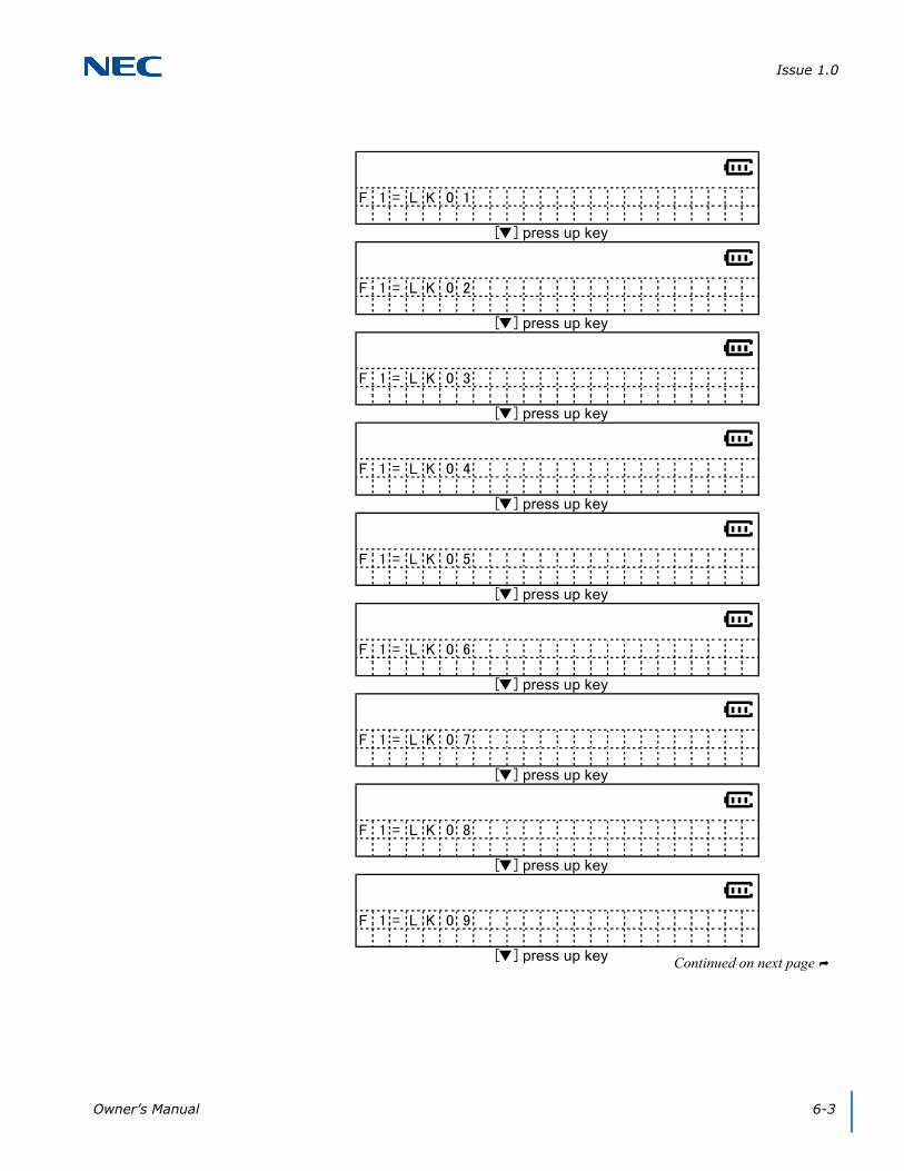
1.1.5 Training Mode (Volume Up Key – Change Each Item Setting)
The up key can change each item setting as illustrated in the following displays (e.g., when the F1 setting is changed, the F1 LED blinks).
The items in the display change in the following sequence:
F1F1(TALK)F2F2(TALK)F3F3(TALK)F4F4(TALK)F5F5(TALK)F6F6(TALK)F7F7(TALK)F8F8(TALK)OFF HOOK RINGF1…
The items in the display change in the following sequence:
LK01LK02LK03LK04LK05LK06LK07LK08LK09LK10LK11LK12LK13LK14LK15LK16LNRSPDRecallFNCANSLK01…
Issue 1.0
Owner’s Manual 6-3
F 1 = L K 0 1
[▼] press up key
F 1 = L K 0 2
[▼] press up key
F 1 = L K 0 3
[▼] press up key
F 1 = L K 0 4
[▼] press up key
F 1 = L K 0 5
[▼] press up key
F 1 = L K 0 6
[▼] press up key
F 1 = L K 0 7
[▼] press up key
F 1 = L K 0 8
[▼] press up key
F 1 = L K 0 9
[▼] press up key Continued on next page

Issue 1.0
6-4 Setup and Operation
F 1 = L K 1 0
[▼] press up key
F 1 = L K 1 1
[▼] press up key
F 1 = L K 1 2
[▼] press up key
F 1 = L K 1 3
[▼] press up key
F 1 = L K 1 4
[▼] press up key
F 1 = L K 1 5
[▼] press up key
F 1 = L K 1 6
[▼] press up key
F 1 = L N R / S P D
[▼] press up key
F 1 = R e c a l l
[▼] press up key
Continued on next page

Issue 1.0
Owner’s Manual 6-5
SECTION 2 HANDSET OPERATION
This operation is one of the examples for the DTZ-8R-1 with an NEC PBX. As a result, it might be different from actual operation on your system. Operation of DTZ-8R-1 in digital mode depends on each PBX specification.
2.1 Switching Between the Wired Phone and Cordless Phone (DTZ-8R-1 Handset)
Press the Base Left key to change to the cordless phone (DTZ-8R-1 Handset). When the cordless phone is selected, there is no message on the LCD. Press the Base Right key to change to the wired phone. When the wired phone is selected, the LCD shows ’DESK TEL’.
F 1 = F N C
[▼] press up key
F 1 = A N S
[▼] press up key
F 1 = L K 0 1
IMPORTANT
❍ The screens in this section are system-dependent and may not match your handset.
❍ Depending on the system the handset may not follow automatic idle return.
Base Left Key Base Right Key

Issue 1.0
6-6 Setup and Operation
2.2 Making a Call to Another Extension
To make a call to another extension:
1. Press the TALK key on the handset. The handset tries to connect to the base station while the “ACQUIRING LINK” message blinks on the LCD.
2. When connected, the handset goes into Talk mode and theTalk icon is turned on and displays the current volume.
Talk Key Speaker Key

Issue 1.0
Owner’s Manual 6-7
3. If the user dials 1,2, 3 the LCD displays the dialed number as they are pressed.
When Base Station is not connected to a PBX, the handset displays “DISCONNECT”.
When the handset cannot connect to the base station, an error tone is emitted and "Out of Range” is displayed for five seconds on the LCD and the handset goes into Standby mode.
The handset cannot go into Talk mode when the wired phone is selected.
Talk Speaker
D I S C O N N E C T
O u t o f R a n g e

Issue 1.0
6-8 Setup and Operation
4. The LCD displays the message, indicating the call is taking place.
5. When the called party answers, the LCD displays a message to indicate the phone is in Talk mode.
Talk Speaker
Talk Speaker

Issue 1.0
Owner’s Manual 6-9
2.2.1 Connection Considerations
1. When the base station is not connected to the PBX, the handset displays “DISCONNECT”.
2. When the handset does not connect to the base station, an error tone is emitted and “Out of Range” message is displayed for five seconds. The handset then goes to standby mode.
3. When a desktop (wired) phone is selected, the handset does not go into Talk mode.

Issue 1.0
6-10 Setup and Operation
2.3 Retrieving a Call to Another Extension
To retrieve a call from another extension:
1. When an incoming call is received from another extension, the handset goes into Incoming Call mode. The display indicates there is an incoming call.
2. If you press either the Talk or dial pad keys (0~9, *, #) or pick the handset from the cradle, the handset connects to the base station and “ACQUIRING LINK” displays.
If the connection is established quickly, the message “ACQUIRING LINK” may not display.
IMPORTANT
❍ Answering a call on the secondary line will differ depending on the system.
❍ Press the center key and use the down arrow to select the ringing line. Press the center key again to answer the call.
Issue 1.0
Owner’s Manual 6-11
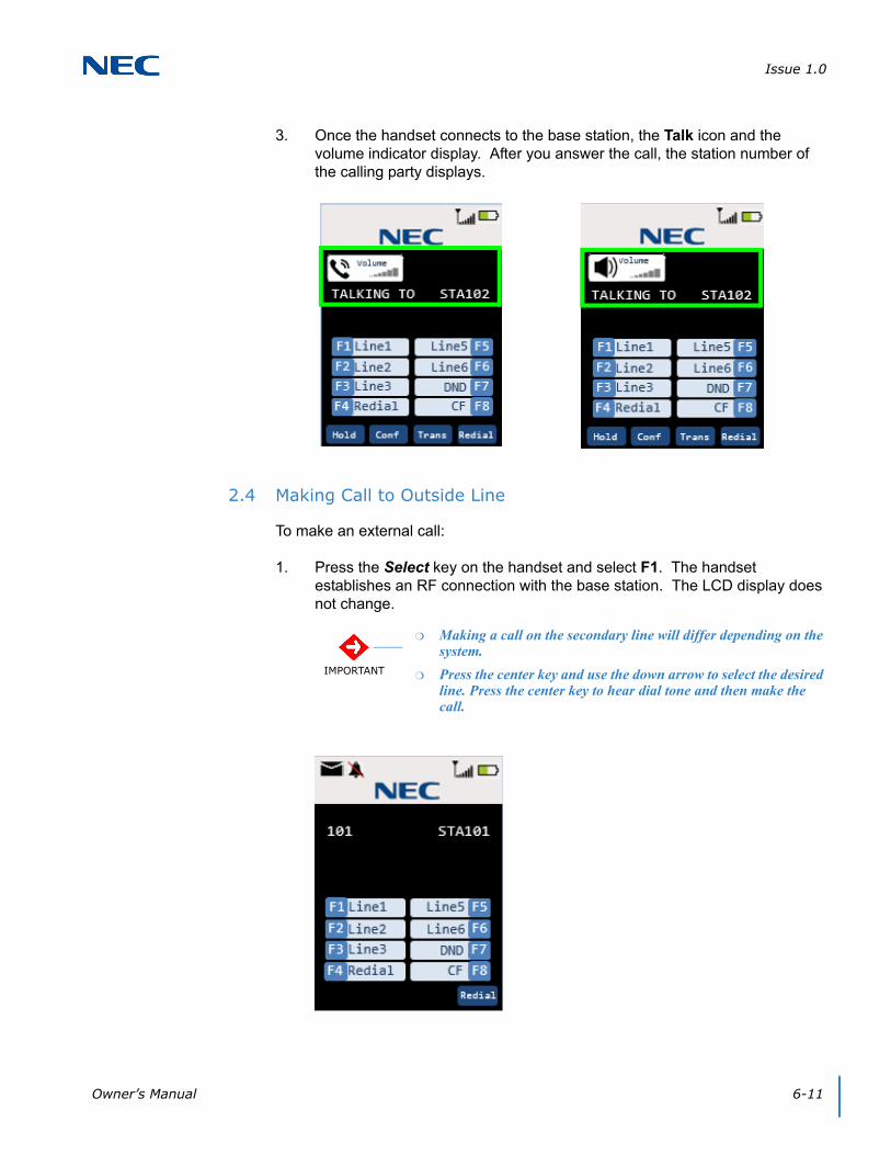
3. Once the handset connects to the base station, the Talk icon and the volume indicator display. After you answer the call, the station number of the calling party displays.
2.4 Making Call to Outside Line
To make an external call:
1. Press the Select key on the handset and select F1. The handset establishes an RF connection with the base station. The LCD display does not change.
IMPORTANT
❍ Making a call on the secondary line will differ depending on the system.
❍ Press the center key and use the down arrow to select the desired line. Press the center key to hear dial tone and then make the call.

Issue 1.0
6-12 Setup and Operation
2. When the RF connection is established, the handset goes into Talk mode and the Talk icon and the volume indicator display. The F1 LED also lights.
When the outside line is not connected with the PBX, “HANG UP” is displayed and you hear a busy tone.

Issue 1.0
Owner’s Manual 6-13
3. If the user dials 1,2, 3 the LCD displays the dialed number as they are pressed.
2.5 Receiving a Call from an Outside Line (Depends on PBX Line)
To receive a call from an external line:
1. When you receive an incoming external call, the F1 LED blinks.
Talk Speaker

Issue 1.0
6-14 Setup and Operation
2. If you press either the Talk or dial pad keys (0~9, *, #) or pick the handset from the cradle, the handset connects to the base station and “ACQUIRING LINK” displays.
If you press the F1 (select key up/down select key), the handset connects to the base station. However, “ACQUIRING LINK” is not displayed.
3. When the RF connection is established, the handset goes into Talk mode and the Talk icon and the volume indicator display.

Issue 1.0
Owner’s Manual 6-15
2.6 Redial (Option)
When the RF link is established between the handset and the base station, you can press the REDIAL key. The last number dialed is shown and the digits dialed are sent to the base station.
Example:
(1) [talk][1][2][3][talk] redial: 123
(2) [talk][1][2][3]……….[1][2][talk] (over 32 digits) redial: 123……12 (up to 32 digits)
(3) [talk][1][2][3][F1][4][5][6][talk] redial: 123
2.7 AutoStandby®
When the handset is in one of the modes listed below, placing the handset on the charger changes it to Standby mode. At this time, a confirmation tone is emitted.
Ringer Volume Setting
Menu Setting
Talk Mode
Trying to Connect to the Base Station
NOTE
❍ An error tone is emitted when redial is empty.
❍ Dial limit is 32 digits, redial stores up to 32 digits in memory.
❍ Redial data is stored in handset memory (EEPROM).
❍ If F1~F12 keys are pressed, the number dialed before the Function key is pressed will be stored in redial memory.

Issue 1.0
6-16 Setup and Operation
2.8 PBX No Service
When the base station is linked to a wired telephone and you press the TALK or Speaker key, there is know acknowledgment from the PBX.
The handset goes into Standby mode and the LCD displays “ACQUIRING LINK”.
2.9 Out Of Range
When in Standby Mode
The handset displays the message “Searching” when the handset cannot find the base station (Out of Range) in Standby mode.
NOTE The handset does not emit a tone when it goes into Standby mode.

Issue 1.0
Owner’s Manual 6-17
When Establishing an RF Link
If the TALK or Speaker key is pressed but the handset cannot establish an RF Link with the base station, the handset emits an error tone and displays the message “Out of Range”.
While Talking
If the handset cannot receive a signal from the base station in about five seconds, it goes to Standby mode and emits an error tone. In this case, the LCD displays “Out of Range”.
If the base cannot receive a signal from the handset in about five seconds, it goes to Standby mode.
Talk/Speaker
After five seconds, returns to searching.

Issue 1.0
6-18 Setup and Operation
2.10 Low Battery
The handset has visual and audible indicators to warn of a low battery condition.
In Standby Mode
The Battery Status icon in the LCD changes to battery low. The “Charge Battery” message blinks on the LCD (ON: 600msec, OFF: 600msec).
In Talk Mode
The Battery Status icon in the LCD changes to battery low. The handset remains in Talk mode and the battery low alert tone is emitted every 30 seconds.
In Other Mode (Excluding Standby Mode and Talk Mode)
The Battery Status icon in the LCD changes to battery low.
2.11 Battery Status
The LCD indicates the battery capacity as indicated in the diagram below.
2.12 Mute
Press the Menu/Mute key in Talk mode. The Mute icon is on an the sound from the microphone is muted.
Press Menu/Mute again to cancel mute. The Mute icon is off.
Finishing Talk mode also cancels mute.
2.13 Handsfree
Press the Speaker key in Standby mode or during Talk mode. The handset switches to Handsfree Talk mode. The Handsfree icon is on.
Press the TALK key in Handsfree Talk mode. The Handsfree icon turns off. The handset switches to Talk mode.
Press the Speaker key in Handsfree Talk mode. The handset cancels Talk mode and switches to Standby mode.
Issue 1.0
Owner’s Manual 6-19
2.14 Headset
To put the handset into Headset mode:
Insert the headset plug in headset jack while in Talk mode or Handsfree Talk mode. The handset switches to the headset.
In the headset condition, the user can change Handsfree mode to Talk mode. However the handset keeps the headset condition.
Insert the headset plug into the headset jack when in handsfree condition. The Handsfree icon remains on.
A tone is emitted from the handset speaker when the headset is connected.
2.15 Volume Setting
The following modes have volume settings: Talk mode, Handsfree Talk mode and headset.
During each mode, you can press the Up (▲) or Down (▼) keys to increase or decrease the volume. As you increase/decrease the volume setting, the setting is displayed on the LCD from Level 1 to Level 6. After the volume is changed, the LCD shows the current volume setting for five seconds.
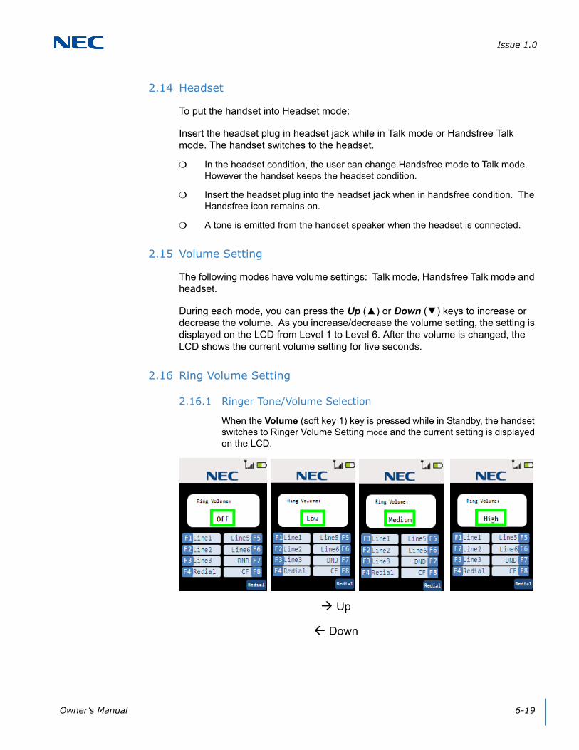
2.16 Ring Volume Setting
2.16.1 Ringer Tone/Volume Selection
When the Volume (soft key 1) key is pressed while in Standby, the handset switches to Ringer Volume Setting mode and the current setting is displayed on the LCD.
Up
Down

Issue 1.0
6-20 Setup and Operation
2.17 Ringer Mute
If the Volume Down key is pressed and held for two seconds while in Standby mode or Incoming Call mode, the handset sets the ringer mute on, turns on the Ringer Mute icon and stops the ringer.
To turn the Ringer Mute off, press and hold the Volume Down key for two seconds; ringer mute is turned off.
NOTE
❍ The handset remains in Ringer Volume Setting mode for two seconds
unless keys are pressed.
❍ You can use the handset to change the ringer volume while in Incoming Call mode. The ringer volume does not appear on the display.
❍ If Ringer Volume is off and the handset is on the charger while in Incoming Call mode, it rings Low, but does not vibrate.
❍ If ringer mute is on, the handset does not ring nor does it vibrate.
❍ Press the TALK key or Speaker key in Ring Volume Setting mode. The handset cancels the ringer volume setting and goes into Standby mode.

Owner’s Manual 7-1
Chapter 7Handset Feature Settings
SECTION 1 HANDSET FEATURES
The handset menu provides access to various features, which you can customize. These features include:
Contacts List - allows you to add and modify your contacts list.
Settings - allows you to adjust several handset settings such as menu timeout, LCD brightness, power save, audio equalizer and key lock.
Sounds - allows you to select a ring tone, turn vibrate and out of range setting on/off and enable/disable key tone.
Language - allows you to select one of three language settings (English, French or Spanish).
Administrator Setting - allows you to register/de-register, change the pin code and scan the site for information about the handset.
Function Key Labels - allows you to assign a label to the function keys.
Key Lock - locks the keys after elapsed time period.
Virtual Function Key - allows you to assign function keys that display on the handset’s LCD.
Base Key Option - allows you to display a Desk and H/S key on the handset’s LCD.
IMPORTANT
The screens in this section are system-dependent and may not match your handset.

Issue 1.0
7-2 Handset Feature Settings
SECTION 2 MAIN MENU
The handset main menu provides access to the various features. The features that are available from the Main menu, allow you to modify various settings as well as access to administrative features.
When you access the Main menu and select one of the menu items, the handset switches to Menu Setting mode.
The handset stays in Menu Setting mode for one minute, unless a key is pressed. When Handset Cancel menu setting is activated or you press the Exit or the End Call key while in Menu Setting mode; the handset switches to Standby mode.
2.1 Accessing the Main Menu
To access the Main menu:
1. Press the Menu key while in Standby mode. The menu list is displayed on the handset LCD.
2. Select the menu items by scrolling up (▲), down (▼), left (◄) or right (►). Press the Select key to open the menu item.
3. Press Exit to go back to the previous screen or Standby mode.
IMPORTANT
The screens in this section are system-dependent and may not match your handset.

Issue 1.0
Owner’s Manual 7-3
SECTION 3 MAIN MENU SELECTIONS
3.1 Contacts
The Contacts menu item allows you to add, edit, delete or dial your contact members.
Use the up/down keys to select the Contacts menu item. Once the Contact menu is displayed, you can make the appropriate changes using the Select key.
3.1.1 List All Contacts
IMPORTANT
The screens in this section are system-dependent and may not match your handset.
Keys available for listing contacts include:
To select contacts:
up (▲) / down (▼) - accesses the next contact in the list (forward/backward).
left (◄) / right (►) - accesses the next five contacts in the list (forward/backward).Select key - When the contact is selected, the details associated with the contact are listed
To edit contacts:Delete key (Softkey 1) - deletes the contents of the selected contact.Edit / Add key (Softkey 2) - edits the contents of the selected contact. If the selected contact is empty, the softkey indicates Add.
To dial from the contact list:Talk/Speaker key - dials the selected contact.

Issue 1.0
7-4 Handset Feature Settings
3.1.2 Show Individual Contacts
Keys available for showing individual contact members include:
To select contacts:
up (▲) / down (▼) - accesses the next contact in the list (forward/backward).Back key - returns to the List screen.
To edit contacts:Delete key (Softkey 1) - deletes the contents of the selected contact.Edit / Add key (Softkey 2) - edits the contents of the selected contact. If the selected contact is empty, the softkey indicates Add.
To dial from the contact list:Talk/Speaker key - dials the selected contact.

Issue 1.0
Owner’s Manual 7-5
3.1.3 Delete Contacts
Select the contact using the Select key. Once the contact is selected, you can delete it.
3.1.4 Edit/Add Contacts
To add a contact:
1. Enter the contact name.
2. Enter the contact number.
3. Save the contact.
Contact Name
If adding a new contact, enter the name you wish to assign to the contact. If you are editing an existing contact, enter the name to access the contact.
A contact name is a maximum of eight characters.
Keys available for deleting a a contact include:
To delete contacts:Yes key - deletes the contact from the list, emits a confirmation tone and returns the display to the previous screen.No key - Does not delete the contact and returns the display to the previous screen.

Issue 1.0
7-6 Handset Feature Settings
Keys available for editing/adding contact members include:Back key - returns to the previous screen.Next key - accesses the Number Edit screen.123/abc key - toggles between numeric and alphabetic ‘keypad’.
123 - allows numeric input.abc - allows alphabetic input.
Delete key - deletes a character.Right/Left key - moves the cursor to the right or left one character.
Alphabetic Input:
Dial keys:Dial 1 : @.-_&'^?!(),\\/:;~=+1 Dial 2 : abcABC2 Dial 3 : defDEF3 Dial 4 : ghiGHI4 Dial 5 : jklJKL5 Dial 6 : mnoMNO6 Dial 7 : pqrsPQRS7 Dial 8 : tuvTUV8 Dial 9 : wxyzWXYZ9 Dial 0 : 0 Dial * : * Dial # : #
Add: Edit New
Edit: Rename

Issue 1.0
Owner’s Manual 7-7
Contact Numbers
If adding a new contact, enter the number you wish to assign to the contact. If you are editing an existing contact, change the number used to dial the contact.
A contact number is a maximum of 24 digits. If the number is over 16 digits, the number displays on two lines; 16 digits on the first line of the line of the display and the remaining digits on the second line.
Keys available for editing/adding contact members include:Back key - returns to the previous screen.Next key - accesses the Number Edit screen.Delete key - deletes a character.Save key - saves and stores the contact. A confirmation tone is emitted.
After two seconds, the display returns to either the Contact List or Individual Contact List view.
Add: Edit New
Edit: Rename
Contact Saved

Issue 1.0
7-8 Handset Feature Settings
3.2 Settings
The settings menu items allows you to access and modify the DTZ-8R-1 settings.
Use the up/down keys to select the setting options. Once the settings menu is displayed, select the settings using the Select key.
3.2.1 List Settings
3.2.2 Menu Timeout Settings
Keys available for listing settings options include:
To select settings:
up (▲) / down (▼) - accesses the next setting in the list (forward/backward).Select key - displays the selected settings menu option screen.
Keys available for timeout values include: Default = 30 seconds.
To select settings:
up (▲) / down (▼) - accesses the next setting in the list (forward/backward).Select key - stores the selected timeout value, emits a confirmation tone and returns to the previous settings screen.

Issue 1.0
Owner’s Manual 7-9
3.2.3 Brightness Settings
3.2.4 Power Save Settings
While in Standby or Talk mode, one minute elapses (without pressing any keys) and the phone enters Power Save mode.
To exit Power Save mode:
1. Press any key.
- OR -
Remove the handset from the charger unit.
Keys available for brightness settings include: Default = MAX.MAX = 100%HIGH = 80%MID = 60%LOW = 20%
To select settings:
up (▲) / down (▼) - accesses the next setting in the list (forward/backward).Select key - stores the selected timeout value, emits a confirmation tone and returns to the previous settings screen.
Keys available for power save settings include: Default = On.On = LCD is in sleep mode, the LCD back light is offOff = LCD back light is dimly lighted
To select settings:
up (▲) / down (▼) - accesses the next setting in the list (forward/backward).Select key - selects the desired setting and stores the selection. A confirmation tone is emitted. The previous screen (setting list) is displayed.

Issue 1.0
7-10 Handset Feature Settings
3.2.5 Key Lock Settings
This menu item allows you to enable/disable the handset Key Lock function.
To enable/disable the Key Lock function:
1. Use up/down arrow to access On (to enable) or Off (to disable).
2. Press Select.
If the Key Lock function is enabled while the handset is in Standby mode, the keys are locked after 15 seconds elapse. You can temporarily unlock the keys for handset operation.
To unlock the keys:
1. Press and hold for two seconds.
Enable/Disable Key Lock:
Keys available for key lock settings include: Default = Off.On = Enable Key Lock functionOff = Disable Key Lock function
To select settings:
up (▲) / down (▼) - accesses the next setting in the list (forward/backward).Select key - selects the desired setting and stores the selection. A confirmation tone is emitted. The previous screen (setting list) is displayed.
Temporarily Unlock Keys:
Keys available when unlocking the keys include:
key - unlocks the keys until the handset is inactive for more than 15 seconds.
When you receive an incoming call, the Key Lock function is disabled for the duration of the call.

Issue 1.0
Owner’s Manual 7-11
3.3 Sounds
The sounds menu items allows you to access and modify the DTZ-8R-1 ring tones, out of range alerts, key tones and turn vibrate on and off.
Use the up/down keys to select the menu items. Once the settings menu is displayed, you can make the appropriate changes using the Select key.
3.3.1 Sounds List Settings
3.3.2 Sounds Ring Tone Settings
Keys available for listing sounds settings include:
To select settings:
up (▲) / down (▼) - accesses the next setting in the list (forward/backward).Select key - selects the desired setting and displays the options for the selected setting.
Keys available for ring tone settings include: Default = Type A.
To select settings:
up (▲) / down (▼) - accesses the next setting in the list (forward/backward).Play key - plays a sample of the ringer tone for two seconds.Select key - selects the desired setting and stores the selection. A confirmation tone is emitted. The previous screen (setting list) is displayed.
Issue 1.0
7-12 Handset Feature Settings
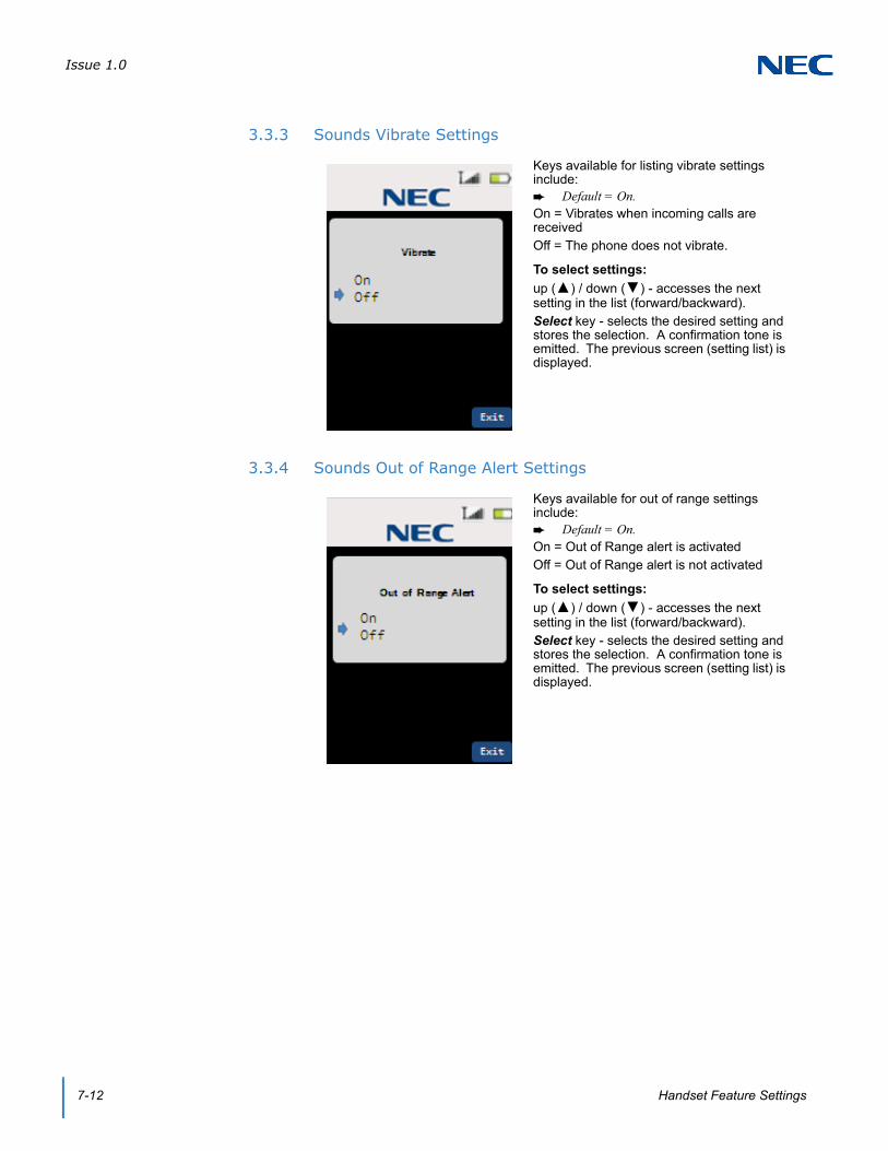
3.3.3 Sounds Vibrate Settings
3.3.4 Sounds Out of Range Alert Settings
Keys available for listing vibrate settings include: Default = On.On = Vibrates when incoming calls are receivedOff = The phone does not vibrate.
To select settings:
up (▲) / down (▼) - accesses the next setting in the list (forward/backward).Select key - selects the desired setting and stores the selection. A confirmation tone is emitted. The previous screen (setting list) is displayed.
Keys available for out of range settings include: Default = On.On = Out of Range alert is activatedOff = Out of Range alert is not activated
To select settings:
up (▲) / down (▼) - accesses the next setting in the list (forward/backward).Select key - selects the desired setting and stores the selection. A confirmation tone is emitted. The previous screen (setting list) is displayed.

Issue 1.0
Owner’s Manual 7-13
3.3.5 Sounds Key Tone Settings
Keys available for sounds settings include: Default = On.On = Key Tone function is enabledOff = Key Tone function is disabled
To select settings:
up (▲) / down (▼) - accesses the next setting in the list (forward/backward).Select key - selects the desired setting and stores the selection. A confirmation tone is emitted. The previous screen (setting list) is displayed.

Issue 1.0
7-14 Handset Feature Settings
3.4 Language
The language menu items allows you to access and modify the DTZ-8R-1 language settings. There are three languages available; English, French and Spanish.
Use the up/down keys to select the menu items. Once the settings menu is displayed, you can make the appropriate changes using the Select key.
3.4.1 Language Settings
3.5 Administrator Settings
The settings menu items allows you to access and modify the DTZ-8R-1 administrator settings. These settings allow the administrator to register/de-register handsets, change pin codes and conduct a site survey to assess the condition of the handsets.
Use the up/down keys to select the menu items. Once the settings menu is displayed, you can make the appropriate changes using the Select key.
Keys available for listing language settings include: Default = English.Available language:EnglishFrenchSpanish
To select settings:
up (▲) / down (▼) - accesses the next setting in the list (forward/backward).Select key - selects the desired language setting and stores the selection.

Issue 1.0
Owner’s Manual 7-15
3.5.1 Administrator List Settings
3.5.2 Administrator Registration Settings
This setting allows the administrator to register the handset.
To register the handset:
1. Press and hold the left key on base station until the blue LED blinks (three seconds).
2. Select Registration from the Administrator Settings menu list.
3. Press the Select key. The LCD displays the Registration screen.
4. Enter the Registration Pin number.
5. Press OK to send the pin number to the base station.
Keys available for listing the administrator settings include:
up (▲) / down (▼) - accesses the next setting in the list (forward/backward).Select key - selects the desired setting and displays the screen.

Issue 1.0
7-16 Handset Feature Settings
.
Handset searches for the base station:
Keys available when registering the handset include:
Cancel key - exits registration mode.
Enter Registration Pin:
Keys available when registering the handset include: Default = 1234.
Delete key - deletes one digit.
Dial (0~9) key - numeric keys to used to enter the pin code.
OK key - sends the registration pin to the base station.

Issue 1.0
Owner’s Manual 7-17
.
Finish Registration:
Keys available when registering the handset include: After five seconds, the handset switches to
one of the following modes; depending on the success or failure of handset registration.
If registration is successful, the handset switches to Standby mode.
If the registration fails, the handset switches to De-register or Standby mode.

Issue 1.0
7-18 Handset Feature Settings
3.5.3 Administrator De-registration Settings
This setting allows the administrator to de-register the handset.
To de-register the handset:
1. Use the up/down key to select the handset you want to de-register.
2. Select Yes to de-register the handset.
Select handset:
The handset number is displayed.
Keys available when de-registering the handset include:
up (▲) / down (▼) - accesses the next setting in the list (forward/backward).Select key - selects the desired setting and stores the selection. Displays the Confirmation screen.
De-register the handset:
Keys available when de-registering the handset include:
Yes key - starts de-registration.
No key - returns the handset to Standby mode.

Issue 1.0
Owner’s Manual 7-19
.
Finish Registration:
Keys available when de-registering the handset include: If de-registration is successful, the LCD
displays the message indicating the handset is not registered. You can register the handset again using the Regist key.
Regist key - starts registration.
If de-registration failed, the handset switches to Standby mode after five seconds have elapsed.

Issue 1.0
7-20 Handset Feature Settings
3.5.4 Administrator Change Pin Code Settings
This setting allows the administrator to change the pin code.
To change the pin code:
1. Select Change Pin Code from the Administrator Setting List.
2. Press the Select key.
3. Change the pin code on the Change Pin Code screen.
4. Press OK to register the new pin code.
When this setting is selected, the handset starts communicating with the base station to obtain the pin code. The base station sends the pin code to the handset and it is displayed on the handset’s LCD.
Keys available when changing the pin code include:
Delete key - deletes one digit.
Dial (0~9) key - numeric keys used to enter the pin code.
OK key - sends the registration pin to the base station. A confirmation tone is emitted.

Issue 1.0
Owner’s Manual 7-21
3.5.5 Administrator Site Survey Settings
This setting allows the administrator to initiate a site survey to collect information about the handsets.
To change the pin code:
1. Select Site Survey from the Administrator Setting List.
2. Press the Select key.
3. On the Site Survey screen, press the Scan key. The results of the scan are displayed on the handset’s LCD.
Scan for information:
This screen displays the following information:Band - the carrier band for the handset.Condition - Good / Fair / Poor Clear Slot - number of clear slots (total number of slots is 12).Number of Base - the number of the base station.
Keys available when requesting a site survey include:
Scan key - begins scanning for clear slots and the number of the associated base station.Sync key - begins Sync display mode.
Scanning begins collecting information (this takes about 30 seconds).

Issue 1.0
7-22 Handset Feature Settings
3.5.6 Administrator Site Survey Settings - Sync Display Mode
To start Sync Display mode:
Press the Sync key.
Scan complete; information displayed:
The results of the scan are displayed in the LCD.Band - the carrier band for the handset.Condition - Good / Fair / Poor Clear Slot - number of clear slots (total number of slots is 12).Number of Base - the number of the base station.
Keys available when requesting a site survey include:
Scan key - restarts scanning for clear slots and number of base stations.
Sync key - begins Sync Display mode.
Start Sync Display mode:
When the Sync key is pressed, the Sync Display mode displays the following information:
Ch - the current channel number.Slot - the current slot number.RSSI - the current RSSI (Receive Signal Strength Indication) value.BER - the Bit Error Rate.RFPI - the RFPI (Radio Fixed Part Identity) or base station ID.H/O - Hand Over Enable/DisableLost - Lost counterL - status (locked or unlocked)

Issue 1.0
Owner’s Manual 7-23
3.6 Function Key Labels
The Key Label menu item allows you to assign, edit or delete labels for the eight function keys.
To access the Key Labels menu:
Select Key Labels from the main menu using the Select key.
3.6.1 Key Label List Settings
This screen allows you to access the function key labels. Once you have selected the function key, you can assign, edit or delete the label.
There are eight function keys that can be assigned labels.
Keys available when accessing the key labels include:
up (▲) / down (▼) - accesses the next setting in the list (forward/backward).Select key - selects the desired label. Delete key - deletes the label name.On/Off key - toggles between enabling/disabling the function key.

Issue 1.0
7-24 Handset Feature Settings
3.6.2 Key Label Name Edit Settings
This menu item allows you to edit the name of the function key label.
A maximum of eight characters can be stored for each label.
Keys available when changing the label name include:123/abc key - toggles between numeric and alphabetic ‘keypad’.
123 - allows numeric input.abc - allows alphabetic input.
Alphabetic Input:
Dial keys:Dial 1 : @.-_&'^?!(),\\/:;~=+1 Dial 2 : abcABC2 Dial 3 : defDEF3 Dial 4 : ghiGHI4 Dial 5 : jklJKL5 Dial 6 : mnoMNO6 Dial 7 : pqrsPQRS7 Dial 8 : tuvTUV8 Dial 9 : wxyzWXYZ9 Dial 0 : 0 Dial * : * Dial # : #
Right/Left key - moves the cursor to the right or left one character (only available for alphabetic input).Delete key - deletes the character where the cursor is positioned.Save key - stores the function key label name.

Issue 1.0
Owner’s Manual 7-25
3.6.3 Key Label Delete Label Settings
This menu item is used to delete a function key label name. This screen is displayed when the Delete key is pressed on the Edit Function Key Label screen.
To delete the label name:
Press Yes.
Keys available when changing the pin code include:Yes key - deletes the function key label.Not key - returns to the previous screen.

Issue 1.0
7-26 Handset Feature Settings
SECTION 4 ADDITIONAL HANDSET FEATURES
4.1 Virtual Function Keys
You can access virtual function keys by entering Virtual Function Key mode. You can enter Virtual Function Key mode while the handset is in Standby mode, when receiving an incoming call or while talking.
To enter Virtual Function Key mode:
Press the Select / Talk or Speaker key.
IMPORTANT
The screens in this section are system-dependent and may not match your handset.
Keys available when switching to Virtual Function Key mode include:
up (▲) / down (▼) - accesses the next setting in the list (forward/backward).
Select key / Talk key / Speaker key - sends the function key code to the base station.

Index i
INDEX
Numerics16-hour talk time 1-34-day standby time 1-3
AAC adapter 1-2, 2-2, 3-3, 5-1adapter 5-1administrator
change pin code 7-20de-registration 7-18list 7-15registration 7-15site survey 7-21
sync display mode 7-22answer
any key 1-3applying power to 3-3AutoStandby 2-3, 6-15
Bback light
keys 1-3LCD 1-3
base unit 1-2, 2-2adapter 5-1controls 4-3power requirements 1-2receive frequency 1-2size 1-2transmit frequency 1-2weight 1-2
batteriesnickel-metal hydride 1-4NiMH 1-4
battery 1-3AAA Ni-MH 1-3batteries 5-1charging 3-3, 3-8charging unit 1-3, 2-3cleaning 3-10handset 3-7low indication 3-9, 3-10nickel-metal hydride 1-4rechargeable 2-2, 5-1recycling 1-4safety considerations 1-4
belt clip 2-2, 5-1
CCanadian Standards Association 1-1
certification label 1-1change channel 1-3channel
automatic selection 2-3channel change 1-3charger unit 2-7
buttons 2-5charging
handset battery pack 3-8stand 2-2unit 1-3, 2-3, 3-3
charging unit 5-1cleaning battery contacts 3-10conference key 4-2contacts 7-3
delete 7-5edit/add 7-5list all 7-3numbers 7-7show individual 7-4
conversation mode 4-2cordless LED 4-3CSA 1-1
Ddata transmission speed 1-2direct wall mounting installation 3-4display
LCD 1-3
FFCC 1-2, 1-7FCC Part 15 rules 1-1FCC Part 68 1-2features
automatic channel selection 2-3charging unit 2-3handset
design 2-3volume 2-3
headsetjack 2-3volume 2-3
mute control 2-3single key access 2-3virtual function keys 7-26
frequencycontrol 1-2receive 1-2transmit 1-2

ii Index
Hhandset 1-3, 2-2
battery 1-3battery pack 3-7, 3-8controls 4-1design 2-3features 7-1
administrator setting 7-1base key option 7-1contacts list 7-1function label keys 7-1key lock 7-1language 7-1settings 7-1sounds 7-1virtual functions key 7-1
kit 5-1operation 6-5
AutoStandby 6-15battery status 6-18call extension 6-6handsfree 6-18headset 6-19low battery 6-18making outside call 6-11mute 6-18no service 6-16out of range 6-16receive external call 6-13redial 6-15retrieve call from extension 6-10ring volume 6-19ringer mute 6-20switch to cordless 6-5switch to wired phone 6-5volume setting 6-19
power requirements 1-3receive frequency 1-3size 1-3talk mode 1-3transmit frequency 1-3volume 2-3volume control 1-3weight 1-3
handset featuresvirtual function keys 7-26
handsfree 1-3talk mode 4-2volume control 1-3
headset 5-1installing 5-2jack 1-3, 4-3volume 2-3volume control 1-3
hearing aid compatible 1-2, 1-3
Iindications
battery low 3-9, 3-10installation precautions 3-1installing
direct wall mounting 3-4handset battery pack 3-7headset 5-2selecting location 3-1
Kkeys
any key answer 1-3back light 1-3base key option 7-1conference 4-2hold key 4-2lock 7-1talk key 4-2virtual 7-1virtual function 7-26
kithandset 5-1
Llanguage 7-14
settings 7-14LCD
back light 1-3display 1-3
LEDcordless 4-3NEC multiline terminal 4-3power 4-3
line problems 1-6, 1-7lock keys 7-1
Mmain menu 7-2
selectionsadministrator 7-14contacts 7-3language 7-14settings 7-8sounds 7-11
menusadministrator 7-14contacts 7-3handset 7-2language 7-14main 7-2settings 7-8sounds 7-11
modesconversation 4-2handsfree talk 4-2on-hook 4-2

Index iii
programming 6-1standby 4-2, 7-2talk 4-2training
change item 6-2entry 6-1exit 6-2select item 6-2
modulation 1-2multiline telephone
using 6-1mute control 2-3
NNEC multiline terminal LED 4-3nickel-metal hydride batteries 1-4nickel-metal hydride battery 1-3, 1-4Ni-MH batteries 1-4, 5-1
Ooccupied bandwidth 1-2optional accessories
headset 5-1out of range
alarm tone 1-3detection 1-3
output power 1-2
Pphase lock loop 1-2power LED 4-3power requirements 1-2privacy 1-6programming mode 6-1
Rr/vol key 4-3radio frequency interference 1-1radio interference 1-7range 1-6receive frequency 1-3rechargeable batteries 5-1recycling 1-4regulatory
Canada CS-03 Part V 1-2certification label 1-1FCC Part 15 rules 1-1FCC Part 68 rules 1-2
ringermute 1-3tone 1-3vibrating 1-3
Ssafety
battery 1-4general instructions 1-4
safety information 1-1settings
brightness 7-9key lock 7-10list 7-8menu timeout 7-8power save 7-9
single access key 2-3site location 3-1soft keys 1-3sounds
key tone 7-13list 7-11out of range alert 7-12ring tone 7-11vibrate 7-12
specificationsbase unit 1-2frequency 1-2frequency control 1-2handset 1-3modulation 1-2phase lock loop 1-2power requirements 1-2spread spectrum 1-2
standby mode 1-3, 4-2, 7-2
Ttalk
key 4-2mode 1-3, 4-2
telephonebase unit 2-2belt clip 2-2charging stand 2-2cord 2-2, 5-1
connecting 3-1features 2-3handset 2-2headset 5-1line problems 1-6, 1-7multiline telephone 6-1privacy 1-6radio interference 1-7range 1-6rechargeable battery 2-2wall plate adapter 2-2
telephone cords 5-1temperature
specifications 1-2transmit frequency 1-3

iv Index
Vvirtual function keys 7-26volume
controlhigh 4-3low 4-3maximum 4-3medium 4-3
handset 1-3handsfree 1-3headset 1-3setting 6-19
Wwall mounting
charging unit 2-3direct 3-4
wall plate adapter 2-2


Owner’s ManualDTZ-8R-1
NEC Corporation of AmericaIssue 1.0
Dterm ® Cordless DECT


![Bt Verve 410 Trio Dect Cordless Phone[1]](https://static.documents.pub/doc/80x56/55151411497959021e8b4af6/bt-verve-410-trio-dect-cordless-phone1.jpg)


