AD-A285 813* j' jj REPORT OF DEPARTMENT OF DEFENSE ADVISORY GROUP ON ELECTRON DEVICES SPECIAL TECHNOLOGY AREA REVIEW ON COMPUTER AIDED DESIGN DTIC " S ELECTE OCT 2 8 1994 MARCH 1993 This documrnt has been app'oved for publiz: ',el•4 i and io, ito '94-333588 OFFICE OF THE UNDER SECRETARY OF DEFENSE FOR ACQUISITION WASHINGTON, D.C. 20301-3140 *5
Transcript
AD-A285 813*
j' jj REPORT OF
DEPARTMENT OF DEFENSE
ADVISORY GROUP ON ELECTRON DEVICES
SPECIAL TECHNOLOGY AREA REVIEWON
COMPUTER AIDED DESIGN
DTIC" S ELECTE
OCT 2 8 1994
MARCH 1993
This documrnt has been app'ovedfor publiz: ',el•4 i and io, ito
'94-333588
OFFICE OF THE UNDER SECRETARY OF DEFENSE FOR ACQUISITION
WASHINGTON, D.C. 20301-3140
*5
CLEAREDFOR OPEN PUBLICATION
FEB 19 1993 3DIRECTORATE FOR FREEDOM OF INFORUAATKIN
AND SECURITY RE~VIEW (OASO-PA)DEPARTME~NT OF DEFENSE
THIS REPOI IS A PRODUCT OF THE DEFENSE ADVISORY GROUPON ELECTRON DEVICES (AGED). THE AGED IS A FEDERAL ADVISORYCOMMITTEE ESTABLISHED TO PROVIDE INDEPENDENT ADVICE TOTHE OFFICE OF THE DIRECTOR OF DEFENSE RESEARCH ANDENGINEERING. sr-ATEMENTS, OPINIONS. RECOMMENDATIONS, ANDCONCLUSIONS IN THIS REPORT DO NOI NECESSARILY REPRESENTTHE OFFICIAL POSITION OF THE DEPARTMENT OF DEFENSE.
mu0
PREFACE
The purpose of this study was twofold: to ;iss.es U.S. capabilities in computer aided0 design aw it rtlates to the cost-effective development. deployment and upgrading of military
components and systems; and to determine how DoD could help fill gaps in the currentprogram and significanrly reduce acquisition and life-cycle costs in the future through ahighly coordinated initiative in this area.
S*4 The study was performed by DoD's Advisory Group on Electron Devices-specificallyby AGED's Working Groups A and B, responsible. re.pectively, for coordinating microwaveand microelectronic device development for DoD. The conclusions and recommendation.% thatemerged stem mainly from the information p|wscnted at AGED's 8-10 October 1991 "SpecialTechnology Area Review" (STAR) on Computer Aided Design, and from a continuing review
• of this area by both Working Groups since that time.
Together with Jack Kilhy, AGED Chairman, and Joseph Saloom, Chairman ofWorking Group A. I would like to expre.s my gratitude to all contributors--identified on thefollowing two pages-for their kind assistance and cooperation. This applies particularly to
* Bob Bierig and Randy Rcitmeyer. principal organizers of the CAD STAR, and to Dr. JohnMacCallum, ODDRE/AT. whose support wa., essential to this effort.
Finally. I would like to thank the staff of Palisades Institute for Research Services,Inc. (the AGED Secretariat), which did an excellent job of arringing and managing the actual
• meeting.
b -:c, .,ior Forr !S CRA&I M (
William Howard
-tWi'•;, Chairman, Working Group B- "(Microelectronics)
tv -. :v
fi e
PRINCIPAL CONTRI13UTORS/PARTICIPANTS
* Dr. John M. MacCallum, Jr.Executive Director~ Advisory Group on Electron Devices
ODDRL'AT~ The PentagonWmshingion. DC
W11l1am G. Howard. Jr. Jack Kulby Joseph Saloom*Chairman. %lbrking Gro*p B Chairman. Ad,'istin Gropup tin Chairman. Working Gmup A
Advisori Gnriap an~ Electro Des-ices Elecrimn Devices Advisory Group on Eleca'mn DevicesWAishington. D)C washington. DC Washington, DC
Jacob Abraham Lowell Asphoim James Ayior5IlniversutY of Traio Boeing llnaversit 'v of Virginia
Austim, TX Seattle. WA Charlortesville. VA
lDavld Barton Russell Barton Robert SlerigtIntermetrics. Inc. Penn State University 84~ B TechnnlogvBethesda. MDl UninversitY Part. PA Hopkin ton. MA
Randal "mean Richard Carley Steven CarbonCurnegie Mellon (JniversitY Carnegie Mellon U'iriversitv SYnopsys. Inc.Pittsburgh. PA Pittsburgh. PA Mountain View. CA
Harold Carter Ralph Cavin James ClaryU1niversity 01 . ,nrnnnaut North Carolina State UniversitY Researtch Tryiagle Inst'itueCincintnti, OH Raleigh. NC Research Triangle Park. NC
Donald Close Wayne Dai James Dayo"Hughes Aircraft Co. Universir ' of Califournia NASA-LewisManhattan Beach. CA Santa Cruz. CA Cleveland. OH
Bruce Donecker David Evans Goeff FrankHewlett Packard Co. CalS Solutions Research Triangle InstituteSanta Rosa, CA Rockville, MD) Research Triangle Park. NC
Nancy Giddings Scott Goodwin Andrew Graham*Honeywell SRC MCNC MCC
Minneapolis. MN Research Triangle Park. NC Austi.. TX
Juzstin Harlow John Hines Robert JacksonSRC Wright Laboratory Naval Research LaboratoryResearch Triangle Park. NC Wright Patterson AFB, OH Washington, DC
J.P. Letellier Mit.h Mlinar Nicholas NaclerloNaval Research Laboratory EEsof Inc. DARPAWashington, DC Westlake Village, CA Arlington, VA
Richard Newton Barry Perlman John Prince*University of California U.S. Arm ' LABCOM ETDL University of Arizona
Berkeley, CA Fort Monmouth. NJ Tucson, AZ
- iil -- - -
Robert Pucel Randy Relitmeyer Joel SchoenRaytheon Co. U.S. Army LARCOM ETiL Mitre Corp.Lc.iington. MA Fort Monmouth, NJ Bedfirni, MA
Michael Steer Susan Turnbach Allan WeberNorth Carolina Stati' University ODDR&E SEMATECH 0Raleigh, NC Falls Church, VA A ustin, TX
Matthew Weden Jacob VnfleCALS Program Officer MITFalls Church. VA Cambridge. MA
0
0I
eI
'1S
U _n • I I ,
-" .. : . : = " -" = . : : - = 0
The Advisory Group on Electron Devices (AGED)Special Technology Area Review (STAR)
onComputer Aided Design (CAD)
I Executive Summary
* A . Introduction ........................................... IB. CAD STAR Drivers ...................................... IC. General Findings and Recommendations ....................... 2D. Funding Requirements .................................... 5
* 11 CAD STAR
A . Introduction ........................................... 6B . DoD Needs ........................................... 7C . Vision of CAD ................. ....................... 8
* D. Design Methodology. .................................... i2E . M odels .............................................. 20F. Fram eworks .......................................... 23
III Findings, Recommendations, Payoffs ........................... 31
APPENDICES
I Session Summary Reports
A . Plenary Session ........................................ 39* B. Fram eworks .......................................... 46
C. Rump Session: Frameworks ............................... 49D. M odeling and Simulation ................................. 52E. CA D Tools ........................................... 54F. Rump Session: Modeling and Design Synthesis ................. 58G G. CAE Research and Education .............................. 63
2 Computer Aided Logistics Study (CALS) Recommenuations .......... 673 Context for Future Vision of CALS ............................ 714 Glossary of Acronyms ...................................... 75
0 r ' l II " I Iil
S ...
oC tri Dsg 7
STAR ON COMPUTER AIDED DESIGN
1. EXECUTIVE SUMMARY
A. Introduction
The Advisory Group on Electron Devices (AGED) Special Technology Area Review (STAR)* on Computer Aided Design (CAD) was held in Arlington, VA, on 8. 9, and 10 October 1991.
Five formal sessions addressed: (1) CAD issues that are associated with platforms, electronicsystems, subsystems and components and circuits related to integration of tools (frameworks); (2)topics related to modeling and simulation of electronic devices; (3) topics related to software tools(application programs); and (4) topics related to education and training. In addition, two eveningsessions were scheduled to provide informal discussion of issues associated with electronic devicemodeling, circuit simulatio,. and synthesis. Two unscheduled informal evening sessions wereprovided in response to an audience call for added discussion of issues associated withframeworks and electromagnetic simul--tion.
The purpose of this report is to sammarize and present conclusions about the DoD's positionon Computer Aided Engineering (CAE) and to make recommendations for future initiatives andprograms. Section !1 identifies specific CAD requirements and various DoD investmentopportunities vis-a-vis military compnent/lystem needs. Section III of this report outlines theSTAR's overall findings ard recommendations. Section IV provides a detailed summary of eachof the five CAD STAR sessions.
B. CAD STAR Drivers
The need for a CAD STAR was driven by a variety of DoD system acquisition, maintenanceand cost problems:
"* Systems are becoming too complex to achieve accurate "first pass" design successusing conventional techniques
a Life cycle of equipment is getting longer
"* Technology cycles are getting shorter, resulting in rapid onset of parts obsolescence
"* Current documentation practice is inadequate to support low-cost maintenance andperformance upgrading
"• Low-production military electronics is prohibitively expensive
It was in the aforementioned context that the status of CAD technology, capabilities anddevelopment programs was addressed.
o
S.
-2-
The dominant oljective of DoD investment in advanced CAD is to establish a rapid, cost-effective design and engineering capability to manage the enormous complexity of electronicsystems and reduce acquisition, operation and support costs while improving performance.
The payoffs anticipated floro such an advanced CAD capability include the following:
"* Enable affordable and rapid system upgrades and eliminate parts obsolescence via 0technology insertion
"* Cut frequency of new system introduction in half while maintaining ability to meetchanging threat environments
"* Enable increa•ed performance and reduced volume of Advanced Target Recognition(ATR) processors by 20-30X for Remotely Piloted Vehicle (RPV). missile and othermobile platforms
" Reduce electronic system acquisition cost% by more than 20%;
" Reduce cost of low-volume mi itary system components by lOX, spare parts float to25% of current levels and operation and support cost by $1B/ycar by the year 2(X)5
Key to achieving DoD objectives is fth development of CAD tools to facilitate:
" Concurrent engineering of electronic systems
" Accurate modeling and concurrent simulation and optimizalion of circuit-through-system design. taking into account performance, producibiliky cost, reliability, andtestability
"* Rapid, computer-automated translation of requirements to systcm, ,ubsystem andmicrocircuit designs
"* Rapid ,ytcm design upgradcs in res,,onse to changing needs, or technologyothsolecemc~ne
The CAD STAR brought to the fore the many development programs, both inside and outsideof DoD. that are using CAI) tools for electronic design. documentation, product data exchangeand facilitation of. systems manufacture and logistics. These programs, having different short-termgoals and emphasis, have the long-range goal of using computer-executed software descriptions tofacilitate concurrent engineering and life-cycle management of commercial and defense products.As indicated below, some of these programs extend well beyond the electron device community's
_ _0
-3
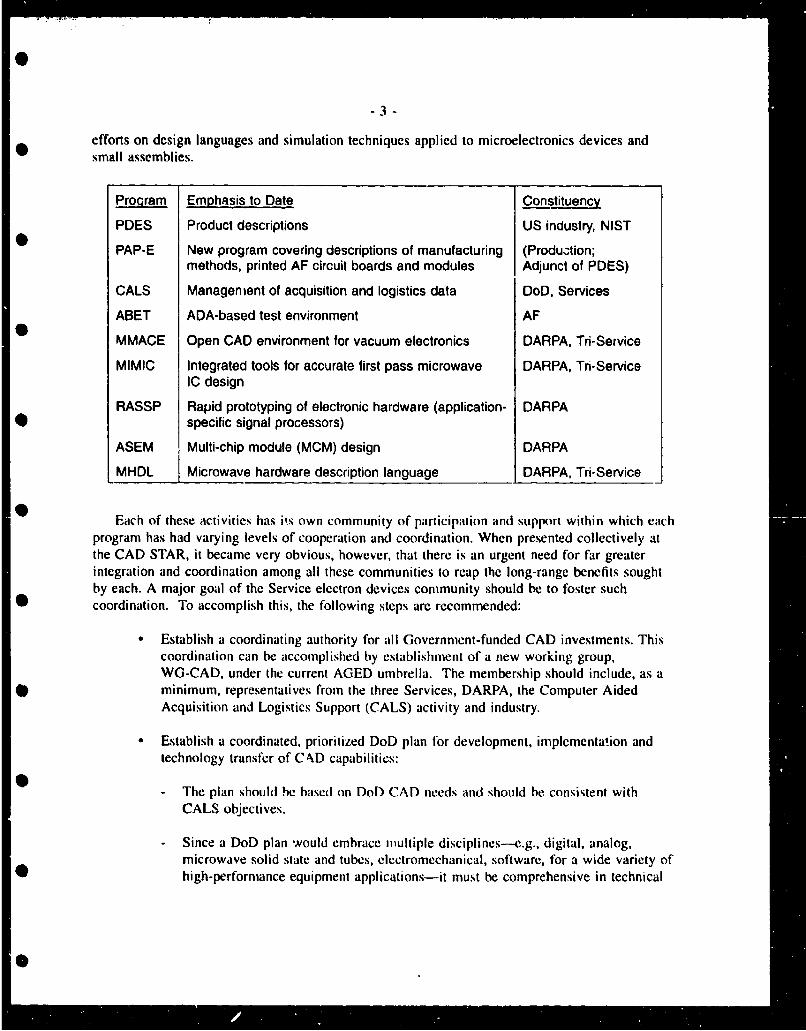
efforts on design languages and simulation techniques applied to microelectronics devices andsmall assemblies.
Program Emphasis to Date Constituency
PDES Product descriptions US industry, NIST
PAP-E New program covering descriptions of manufacturing (Produ..tion;methods, printed AF circuit boards and modules Adjunct of PDES)
CALS Management of acquisition and logistics data DoD, Services
ABET ADA-based test environment AF
MMACE Open CAD environment for vacuum electronics DARPA, Tri-Setvice
MIMIC Integrated tools for accurate first pass microwave DARPA, Tn-ServiceIC design
RASSP Rapid prototyping of electronic hardware (application- DARPA• specific signal processors)
ASEM Multi-chip module (MCM) design DARPA
MHDL Microwave hardware description language DARPA, Tri-Service
Each of these activities has is own community of participation and support within which eachprogram has had varying levels of cooperation and coordination. When presented collectively atthe CAD STAR, it became very obvious, however, that there is an urgent need for far greaterintegration and coordination among all these communities to reap the long-range benefits soughtby each. A major goal of the Service electron devices community should be to foster such
• coordination. To accomplish this, the following steps are recommended:
"Establish a coordinating authority for all Government-funded CAD investments. Thiscoordination can be accomplished by establishment of a new working group,WG-CAD, under the current AGED umbrella. The membership should include, as a
• minimum, representatives from the three Services, DARPA, the Computer AidedAcquisition and Logistics Support (CALS) activity and industry.
"* Establish a coordinated, prioritized DoD plan for development, implementation andtechnology transfer of CAD capabilities:
- The plan should he based on DoD CAD needs and should be consistent withCALS objectives.
- Since a DoD plan would embrace awultiple disciplines--e.g., digital, analog,microwave solid state and tubes, electromechanical, software, for a wide variety of
* high-performance equipment applications-it must be comprehensive in technical
m 0m ta: m - i _=_m _m _m_= • -_. _. ._ . -
-4-
content and uitimate objective. This includes CAD assets necessary to supportconcurrent engineering of electronic systems.
The program plan should include/incorporatc ongoing Service CAD
programs---e.g., the VHSIC Hardware Description Languagc (VHDL), PDES
Application Protocols for Electronics (PAP-E), MIMIC Hardware Description
Language (MHDL), and Microwave and Millimeter Wave Advanced
Computational Environment (MMACE). In addition, an integrated, coherent
CAD capability must also consider the objectives and activities of a number of
DARPA efforts, including the Microwave/Millimeter Wave Monolithic Integrated
Circuit (MIMIC) program, ihe DARPA Initiative on Concurrent Engineering
(DICE), and the Application Specific Electronic Module (ASEM), Rapid
Application-Specific Signal Processor (RASSP), High Performance Computing
Initiative (HPCI) and Microelectronic Manufacturing Science and Technology
(MMST) programs.
" Establish coordination of Service CAD efforts plus PAP-E, MMACE, MIMIC CAD 0
efforts, MHDL and ASEM programs toward common and consistent objectives.
" Plan to execute a tri-Service program for development, implementation and
demonstration of CAD framework/environment standards, validated behavioral and
functional models, data models/methods, chip moduleitotal subsystem/system
simulation, and ,,ýnthesis tools.
At the present time the following areas offer high-return investment opportunities for DoD:
" Models to support accurate computer simulation of performance at all levels of
electronic design-i.e., from device models up to, and including, full system
performance simulation. Specific areas for recommended investment are:
- HDLs to promote data and description standards- Modeling of; devices, circuits, components, subsystems, information,
processes-particularly for DoD specific technologies such as rad-hard digital, 0
high-speed analog, microwaves and electro-optics.- Model validation, including ranges of applicability and intrinsic representational
accuracy, emphasizing microwave, electro-optic and mixed-mode
(analog/digital/analog/microwave) domains.
" Standards: Use DoD research, development and acquisition programs to
opportunistically promote creation, adoption and implementation of standard ways of
"doing things" throughout U.S. industry---e.g., interfacing computer hardware,
process management, and hardware and software integration. Note that this is not a
recommendation to invest in development of DoD specific standards. it is a 0recommendation to more effecrively employ DoD resources to support implementation
of emerging industry standards and, therebv, promote less costly DoD design,
0i
"-5 -
develcpment and acquisition practices. In effect, this is a recommendation for r CALSimplementation stra'egy for electronic technology
Investment in hardware/software codcsign methods and techniques for digital andmixed-mode domains is recommended.
• *Increased DoD investment in R&D is strongly recommended for:
- Generalized design procedures- Automated model building- Process modeling practices- Process management tools- System synthesis techniques- Simulation verification methods
Support for an improved design infrastructure will result from enhanced coordinationof DoD CAD investment and NSF computer-related and CAD-related educationalprogranis.
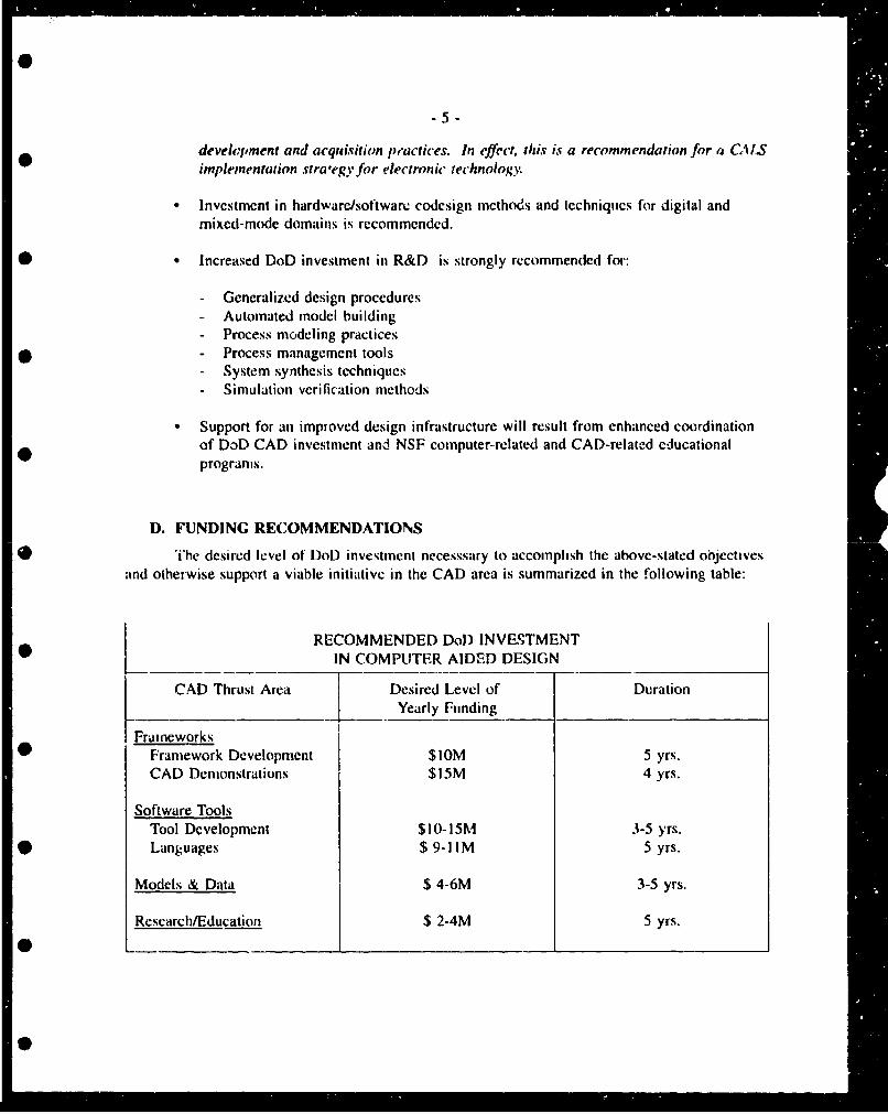
D. FUNDING RECOMMENDATIONS
* The desired level of DoD investment necesssary to accomplish the above-stated objectivesand otherwise support a viable initiative in the CAD area is summarized in the following table:
RECOMMENDED DoD INVESTMENTIN COMPUTER AIDED DESIGN
CAD Thrust Area Desired Level of Duration____________ _ Yearly Funding
Frai neworks
• Framework Development $10M 5 yrs.CAD Demonstrations $15M 4 yrs.
Software ToolsTool Development $10-!5M 3-5 yrs.
* Languages $ 9-IIM 5 yrs.
Models & Data $ 4-6M 3-5 yrs.
Research/Education $ 2-4M 5 yrs.
| -=_ _ == _ _ _--_ _ _ _ _ _ _ _ _ _._ _
11. CAD STAR
A. Introduction
AtAomatiop of desin and production activities has become a central pillar of Government andindustry efforts to shorten development cycles, to reduce development and manufactlifing cost andto improve product quality. The central concept and promise of automation is that theconventional, costly "4csign-build-tes'" cycle can be substantially replaced by a design processbbased on accurate computer simulation of performance. Development/production cycles can beshortened and batch manufacturing can be made "flexible" by integration of engineering andmanufacturing processes.
Over the past decade, the U.S. computer hardware and software industry that supports designand manufacturing automation has grown to be a very large (> $5(1 "'--ir) agglomeration of large.medium and small companies. Unfortunately, few of the products developed so far by thatindustry can be used in an integrated manner---owing to a lack of standards, limited verificationof quality, etc. Despite ever-incrcasing demand within the customer base for products that"communicate" and support integration of functions and processes, the integration of multi-vendordesign automation products has remained an elusive goal.
Since the potential impact of design automation is so profound for DoD procurement ofweapon systems, and since much of the impact is expected to be realized wiihin the design andintegration activity, this STAR suughi ts assess cuifent status and needs of CAD capability frelectronic systems, taking into account the following:
Integration of any computar-automated process requires that models accuratelyrepresent data and that procedures exist common to all software tools, executable oninstalled hardware. Integration also implies that standard procedures for interfacingsoftware exist and, more importantly, are implemented in available products.
Productivity enhancement via automation also implies that the automation systemprovides the human operator with a human-machine ;nterface that is comfortable in thesense that it is as intuitive as possible and makes maximum use of preexistingknowledge--i.e., it does not require the users to relearn the rudiments of theirprofession.
* The DoD, while not a market-dominating customer in automation, has made andcontinues to make substantial investment in areas of ;ntegration (frameworks), models(data, functions and piocesses), and standards focused primarily on digital integratedcircuits. It is estimated that current DoD inve.;tment in areas associated with softwaretools, function and process integration and statidards exceeds $50M/year.
0
0
-7-
B. Dl)o Needs
* Future weapon platforms will have an ever-increasing dependence on highly complex,integrated electronic sensing, command, control and communication systems. Because the missionneeds of these platforms are always projected toward defeating state-of-the-prt threats, systemperformance requirements are driven beyond current industry capability. Aggressive performancespecifications have led suppliers to adopt an often lengthy and costly design, build and verify
* cycle for development of parts and software. Integration and production of systems generallyproceeds after critical parts development is complete. This acquisition process has often led tooverly long and costly development and delayed deployment of needed defense capability.
The following are some of the observed CAD-related problems currently impeding rapiddevelopment, upgrading and affordable logistics support of DoD equipment:
"* The lack of modern electronic system engineering/design methods and powerfulsystem CAD (SYSCAD) capabilities lead to unaffordable costs, unacceptabledevelopmental cycle times and dependency on old/obsolete technologies.
• • The complexity and overall performance requirements of current and future militaryelectronic systems far exceed current product design/prototyping capabilities.
"* The lack of: (a) model libraries at system, subsystem, module, board arJ chip level;and (b) fast, accurate and inexpensive simulation capabilities are major factors thatlead to high military system cost and schedule overruns.
"• The current method of documenting electronic design, text-based level III drawings,does not support rapid insertion of technology for operation and support cost reductionand is a key cause of escalating parts obsolescence problems.
* Throughiout the CAD STAR the following common themes emerged, each signaling a number
of far-reaching needs:
• Ability to integrate multi-vendor software products.
• * Need for improved models at all levels of activity-i.e., models for devices, functions,processes, methodologies, business, etc.
0 Automation implies a culture change and the automation process should be viewed asa long-term activity.
• Implementation of de-facto standards should take precedence over punctiliousestablishment of formal standards since the process associated with formal adoption ofstandards is too time-consuming to support either user or vendor needs.
• DoD support of emerging industry standards, research and development of models for* devices, functions and processes and education associated with use and development
-8-
of CAD is important for both DoD weapon procurement programs as well as thecommercial U.S. CAD industry.
C. Vision of CAD
Design automation, in the context of this STAR report, is defiaed to include all software,hardware and infrastructure support tools for the design of electronic systems. Included in thisdefinition are CAD tools for synthesis and verification of electronic functions from systemsarchitecture and software to chip and board layout, management and integration of such tools withother tools and technologies, user interface technology, special purpose hardware emulators andinterfaces, and design decision support systems, including hardware and software design librariesand design performance estimators (for cost, area, power, speed, reliability, etc.). Technologydevelopment tools such as process and device simulation and design aids, while critical to theestablishment of fabrication technology, are specifically excluded from this definition, which isdirected to system development and realization.
The nature of design automation tools depends strongly on the hardware and softwaretechnologies to be employed in system realization, design methods followed and lifetime support 0requirements for the completed system. Because of these dependencies, development of futuredesign automation technology cannot be carried out in isolation from the design environment. Inthe case of this STAR, the design automation effort must reflect not only the electron devicetechnologies used, it must also take into account developments in the interconnection andpackaging and rapid insertion of electronic technology initiatives that parallcl this activity.
An overall vision of design automation for military systems must encompass the full range ofdesign methods and fabrication technologies to be encountered in system realization. At eachlevel of the system software/hardware hierarchy, the ideal design automation systems must assistthe engineer in constructing design solutions, provide validation capability to assure that themodel meets specifications and design rules, allow evaluation of and comparison between avariety of design alternatives---e.g., software vs. hardware, analog vs. digital, parallel vs. serialarchitecture-with respect to system figures of merit such as cost, performance, powerconsumption, size, weight and reliability, and generate instructions for fabrication and test.
In short, the design automation system of the future must provide the entire suite of toolsneeded to create, evaluate, construct and maintain electronic software and hardware systems.
C.1 The Evolution of Design Automation
Electronic design automation started with a collection of independent CAD tools. The designprocess followed traditional manual methods, with designers using isolated CAD tools to speedindividual tasks. Data interchange between tools consisted of repeated manual entry in theparticular format of each tool used. Human interfaces were unique to each tool. CAD users hadto be skilled operators of tools employed in addition to being skilled designers. This unstructuredapproach to computer assisted design was consistent with the limited computing power available
!S
-9-
in contemporary machines. the centralized, isolated natdre of early computing systems and thethen-existing state of the an of design automation hardware and software techniques.
Workstation computing power, computer networking and design automation techniques havesince advanced significantly. In the case of semiconductor chip design, current tools are nowintegrated into "suites" of interacting software and special hardware tools with consistentdatabases and human interfaces. Workstation computing power now rivals that of all bu! the
• largest mainframes and networking provides access to design libraries and means forgeographically disbursed teams of engineers to collaborate on joint design projects. Advances ingraphics, efficient algorithms and special-purpose computing engines now free the designer fromthe "computrivia" of early, less-user-friendly CAD tools.
• The future outlined by this vision requires extension of design automation techniques shownto be effective for the creation of complex integrated circuit chips to the full range of electronicsystem design tasks and to technologies (such as electromechanical elements, software, microwaveand optical subsystem design) that have yet to be integrated into a comprehensive system designcapability.
C.2 The Framework
A program to architect such a comprehensive, interactive system of design automation requiresan overall plan within which to organize efforts to collect and create its component parts.
* Frameworks provide such a structure for the design automation vision. Frameworks aremodular; they serve to organize and connect a collection of software and hardware tools, each ofwhich performs a limited range of design tasks for given technologies. A framework furtherprovides a basis for interope.ation of these tools by establishing requirements for data interchangeand consistent human interfaces that allow a designer (or team of designers) to seamlessly move
• from step to step according to orderly design methods.
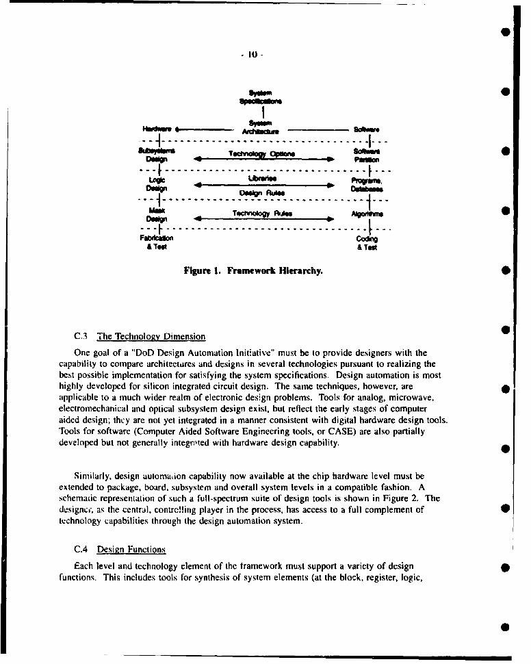
A comprehensive design automation frameworK has multiple dimensions. Fundamentally. it mustspan the system design process from abstract specification and architectural considerations toco-crete, physical design and test and evaluation instructions. Figure 1 shows the levels ofhierarchy considered in the framework vision for this STAR report.
STAR presentations revealed that the tools were most highly developed at the chip designlevel of the framework. Further up the hierarchy, tools became less mature and lessinterconnected.
* As a system design moves from specification to realization, its designers must procecdthrough the framework and deal with it at block, module, logic, circuit, layout and test stages.The design results at each level provide inputs for the tools and activities at the succeeding leveland feedback design results to preceding levels. The framework must facilitate globaloptimization of the system design as wcll as selection of the best choice for each of its elements.
-S
- tO -
5!00
• -- -- ---- -- -- --------------. ... . ...-- --DOP o -Let._ _!!_ 1W Nn
One goal of a "DoD Design Automation Initiative" must be to provide designers with thecapability to compare architectures and designs in several technologies pursuant to realizing thebest possible implementation for satisfying the system specifications. Design automation is mosthighly developed for silicon integrated circuit design. The same techniques, however, areapplicable to a much wider realm of electronic design problems. Tools for analog, microwave,electromechanical and optical subsystem design exist, but reflect the early stages of computeraided design; thcy are not yet integrated in a manner consistent with digital hardware design tools.Tools for software (Computer Aided Software Engineering tools, or CASE) are also partiallydeveloped but not generally integr;,ted with hardware design capability.
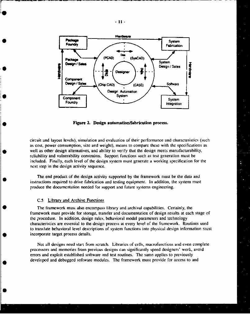
Similarly, design automaion capability now available at the chip hardware level must beextended to package, board, subsystem and overall system levels in a compatible fashion. Aschemaic representation of such a full-spectrum suite of design tools is shown in Figure 2. Thedcsigncc, as the central, contrcl!ing player in the process, has access to a full complement of 0technology capabilities through the design automation system.
C.4 Design Functions
Each level and technology element of the framework must support a variety of designfunctions. This includes tools for synthesis of system elements (at the block, register, logic,
circuit and layout levels), simulation and evaluation of their performance and characteristics (suchas cost, power consumption, size and weight), means to compare these with the specifications aswell as other design alternatives, and ability to verify that the design meets manufacturability,reliability and vulnerability constraints. Support functions such as test generation must beincluded. Finally, each level of the design system must generate a working specification for thenext step in the design activity sequence.
The end product of the design activity supported by the framework must be the data andinstructions required to drive fabrication and testing equipment. In addition, the system mustproduce the documentation needed for support and future systems engineering.
C.5 Library and Archive Functions
The framework must also encompass library and archival capabilities. Certainly, theframework must provide for storage, transfer and documentation of design results at each stage ofthe procedure. In addition, design rules, behavioral model parameters and technologycharacteristics are essential to the design process at every level of the framework. Routines usedto translate behavioral level descriptions of system functions into physical design information mustincorporate target process details.
Not all designs need start from scratch. Libraries of cells, macrofunctions and even completeprocessors and memories from previous designs can significantly speed designers' work, avoiderrors and exploit established software and test routines. The same applies to previouslydeveloped and debugged software modules. The framework must provide for access to and
Sz
-12-
selection from a catalog of prior hardware and software designs in much the same way thattraditional engineers have had access to standard logic products for use in conventional designs.
Finally, the framework must provide for archives of past designs so that those responsible forlife cycle system support will be able to reproduce today's parts using the production processes oftomorrow. Further, design databases must be accessible for rapid and affordable system upgrades.
C.6 DoD's Role •
The Department of Defense and its contractors and suppliers have been important users ofdesign automation technology. While DoD activities have supported development of specific toolsand libraries, commercial design automation firms and fabrication service providers (such asApplication Specific Integrated Circuit (ASIC) suppliers) have provided most of the tools that arenow in widespread use for integrated circuit design and have led the way in connecting themtogether.
Perhaps the most effective recent DoD activity in support of design automation technologydevelopment was the establishment of VHDL as an ANSI/IEEE standard. Work is also completeto make VHDL a Federal Information Processing Standard (FIPS) language for behavioral and 0structural description of system design elements. The CALS standards for logistic supportdocumentation have also had an impact. By promoting these standards and encouraging theiradoption by commercial tool producers, DoD has made an important contribution to a systemdesign automation framework. It is important to note, however, that much more remains to bedone-in putting these standards into widespread practice and in developing languages fordocumenting other domains, such as the MHDL project for microwave systems.
The size of the task of developing and propagating all the tools and techniques required topopulate frameworks and associated libraries described above is well beyond the resourcesavailable to the DoD. That job will require the kind of broad-based, creative development effortthat only firms competing in the general market can mount. Organizing and establishing the •structure and standards required for an electronic systems design framework, however, requires thekind of coordination and encouragement that DoD is well-positioned to provide. A Do) initiativeto define and support development of framework and library technology would not only result inresilient, continually evolving design automation for commercial as well as DoD use, it wouldfacilitate the efforts of independent enterprises to speed the development of the tools and •techniques needed to fill in the framework.
1). Design Methodology
D. I Introduction
Design methodology impacts all areas of CAD and CAE, simulation, test, synthesis, education,etc. While a complete discussion of this topic cannot be taken strictly from the CAD STARpresentations, since design methodology was not a specific session or topic at the meeting, many
iN a IS
-13-
key ideas and recommendations relating to design methodology were presented and will beaddressed below.
It has been estimated that engineers spend from 50% to 90% of their time engaged in"extraneous" activities. Of course, some non-engineering activity is unavoidable, but it is wellknown that engineering productivity can be greatly enhanced by CAE, as can an E.E.'sproficiency in a wide variety of necessary associated diciplines-mechanical, thermal, packaging,statistics, testing, etc. Improvements in design methodologies must be made by considering all ofthe tasks performed by a designer, rather than by developing specific tools which garnerindividual task improvements. The principles of concurrent engineering require that at least someform of parallelism exists and that more than one operation happens more or less at the sametime. Properly integrated, these concepts can yield excellent productivity increases.
D.2 Design Methodology
Design is the process by which requirements, specifications, and design goals are transformedinto a functional or structural form that fulfills the requirements. Except at the lowest level,design is done hierarchically by partitioning a design into several sub-designs, each with its
* assigned specifications, that operate togeiher to form the system. This top-down design process,where specifications drive the design, is essential to rapid and affordable military systemdevelopment and delivery. This emphasis oi specification-driven acquisition requires that theDoD take particular interest in top-down design methodology, including such aspects as synthesisand specification analysis.
At present, state-of-the-art electronic system design cannot be performed totally in a top-downfashion using CAE tools---e.g., via synthesis. Comprehensive synthesis tools encompassing allareas of electronics and operating over multiple levels (from system to chip), are not realisticwithin the next 10-20 years. Thus, computer-assisted iteration of design alternatives andpossibilities, at various; levels of abstraction within the design hierarchy, will be necessary in the
• near term. This points up the need for precise communication of multidisciplinary informationwithin a design hierarchy. Therefore, it is clear that we must continue to build CAE systems withthe user at its heart and we must further develop means to facilitate multidisciplinary informationflow within CAE systems. Andy Graham of the CAD Framework Initiative (CFI), a CAD STARpresenter, recommends placing emphasis on developing information modeling technology, not justspecifications and requirements. User-oriented CAD and design documentation automation shouldbe encouraged while work continues to achieve higher levels of synthesis.
D.3 Electronic Disciplines
* The terms system, digital, analog, and microwave are often used as adjectives to modeling,simulation, and synthesis-e.g., digital synthesis, microwave modeling, system simulation. Thedistinctions among these adjectives are not standardized, nor are they clearly differentiatcd. Forexample, a component might be viewed as a system, digital, analog or microwave element,depending upon its usage and the type of analysis being performed. The fact that we cannotreadily categorize parts was illustrated by Bill Richards of Scott Goodwin-Johnson, whose talk on"digital modeling" focused on what many would consider analog effects: charge-based models,
i S ' •" -
-14-
such as drift/diffusion transport equations. It is clear that design methods (and modeling) mustaccount for a muitiplicity of viewpoints, even relative to a single component.
Today, system simulation usually refers to tactical and operational simulation. Thesesimulations generally treat the system in an abstract manner and are many times removed from theunderlying hardware design. Coupling hacdware-level simulation into the tactical and operationalsimulations in order to evaluate systems before prototyping is one of the areas for designmethodology improvement. DoD now funds many tactical and operational (and hardware-level)models and simulations during major system proý.urement. Efficiencies may be achieved bycoordinating or commercializing system simulation used throughout DoD programs.
D.4 Embedded Software
It is clear that embedded software is becoming an ever-increasing percentage of system 0functionality and cost, making software development and hardware/software (HW/SW) codesign akey DoD need. Several speakers recognized this need: Joel Schoen of MITRE said "10% ofelectronic processing system functionality was achieved via software in the 1960's; today it's90%." Andy Graham of CFI recommended that CAD developers "catalyze basic integration ofCAEJCASE/Computer Aided Manufacturing (CAM) disciplines driven by realistic scenarios," andRichard Newton of UCB pointed out "that current approaches to hardware/software design aredoomed" because the current approach is to simply paste together separate products. Since a largeportion of system expense stems frequently from embedded software, HW/SW codesign is a primearea for DoD-funded design methodology initiatives along with CAD tools, including synthesis,simul tion, and verification tools.
D.5 Models and Simulation
Modeling and simulation allow one to predict the performance of a proposed configuration.However, because advances in electronics technology outpace progress in CAE technology,designers usually are obliged to work on next-generation products with CAE tools and models •which only support, at best, current technology. The increasing complexity of electronic circuitsand systems requires ever-greater simulation accuracy and capabilities to verify performance.Since electronic parts are increasingly made using "non-breadboardable" parts (MIMICs, ASICs,etc.). accurate modeling and simulation are required to produce single-pass, co!,t-effective parts.This reliance on modeling and simulation is also necessary due to higher speeds/frequencies and 0denser packaging. Thus, advanced design methodologies and modeling aaid simulation techniquesmust be developed which can be adjusted to suit designer needs that are consistent with availabletechnology.
Various types of models are used to represent a .single electronic component (previouslydiscussed in Section D.3). A model is a representation of reality based on some physical andmathematical characteristics, which may be validated by measurement. The a.sumptions andunderlying physics captured in the model determine the validity and accuracy of the model. Inaddition to accuracy, simulation speed is also an important characteristic of a model. Forexample, FET models based on a multitude of Monte-Carlo simulations of electrons flowing andscattering in the channel have been developed in a form that some would cite as an "ultimate"
- 15-
model. This method will yield accurate results, though very slowly. Other modeling approaches,however, could potentially be just as accurate for a particular application while executing much
• faster. Although it may be difficult to capture detailed performance in abstract, quickly executingmodels, it is rot impossible. Many forms of modeling and simulation are necessary and all havetheir place. The designer must have a variety of model and simulation types available and be ableto direct the CAE system in application of models appropriately.
There is a need for improved mo&is, across all disciplines of electronics, which allow theincorporation of statistical data and relationships. Far too often, models and simulation tools aredeveloped without regard to the fact that parts must be manufactured and that all physicalprocesses exhibit variations. The problem is not totally solved just by having models andsimulators which allow statistical information. Techniques must be developed to feedmanufacturing information back into the models and simulation.
Also needing improvement are the tools that assist in the development of models. Asemphasized by CLSI Solutions, "A means to automate the modeling of existing parts ismandatory." This supports the more general statement made by Andy Graham of CFI that"research is needed on new design methodologies and process management tools." Further
* research on general design methodologies and automated model building is an activity whichcould greatly benefit DoD.
Also, both CFI and CLSI Solutions agreed that only 5-10% of electronic design content isbeing simulated. The underlying question is why this is so. Potential answers are: (1) becauseappropriate simulation tools don't exist, (2) because they exist but are too expensive, (3) becausecomponent models of one or more key parts either do not exist or are incompatible with othermodels being used. Whatever the case, standardized models are clearly needed.
D.5.1 High-Performance Digital/Mixed-Signal Circuit Simulation and Modeling
* The growing complexity and speed of system components directly influences designmethodologies. At the CAD STAR it was the perception of several speakers that the sheer sizeand number of parts in modern digital systems are preventing rapid and affordable gate-levelsimulation of the system as a whole. They also claimed that the great number of parts ismandating a synthesis approach. Thus, accelerated simulation and powerful synthesis were
* predicted to be key factors in future design methodologies.
Features are being added to digital simulation and modeling to accommodatemicrowave/analog effects. For instance, digital simulators now use the concept of "drive-strength"to effectively model characteristics of the output circuit electronics. These effects are bettermodelcd by analog-type simulators. Also, tools to model cross-talk on circuit traces are offered indigital CAD packages (cross-talk is a coupled transmission line problem). These effects, whichare not directly handled in a digital simulation, are becoming more important as density and speedincrease.
Looking beyond microwave/analog effects as "add-ins" in digital simulators, the electronics* industry is now facing the design and simulation of highly integrated parts with both
- 16-
analog/microwave and digital functionality (the so-called "mixed-mode" problem). The technicalfeasibility and cost-effectiveness of placing such mixed-mode functions on a single chip makesmixed-mode simulation and CAD an area of active commercial interest.
Commercial forces are dominant in the relatively large digital CAD market. However, asexpressed at the CAD STAR, lack of accurate models remains a problem. The growing use ofVHDL is likely to have a tremendously positive imnact en this problem. It will be beneficial todevelop other standards and VHDL modeling practices to provide seamless model interoperation.
D.5.2 Analog Circuit Simulation and Modeling
The Spice program and its derivatives have dominated analog simulation for more than 20years. While a good variety of analog simulation types such as transient analysis, DC operatingpoint, and AC analysis are available in Spice, analog modeling and simulation problems are far •from being solved. Since models are built into the simulator, only ex*erts can effe:tively add oralter models. Although the macro-modeling capability in later Spice versions has allowed theaverag: user or library maker to add models, it is limited to only those expressible ..scombinations of built-in or other macro models. While this has sufficed, it does not create aneffective model-building cnvironment-i.e, an environment where models can be developed andshared in some common form.
The Saber product by Analogy (as discussed by ]an Getreu of Analogy) is a significant recentexample of a non-Spice solution for analog simulation. It has been recognized that the "solver"necessary in transient analysis-i.e., one that solves ordinary differential equations-is applicableto other domains (mechanical, thermal) as well. Digital simulation features have been added to 0Saber, allowing it to perform mixed analog and digital simulation. The MAST languagedeveloped for Saber allows arbitrary models to be developed and shared with other Saber users.Saber has met with limited acceptar.ce due to its relatively high price and complexity, lack ofstandardization of MAST, its. "workstation" orientation (no PC version), and the wide acceptanceof Spice. However for system designers, it is really a step forward, allowing integrated analog,digital, mechanical, and thermal simulation.
Contrary to tl-." digital model availability situation, analog part suppliers largely can onlyprovide "data sheet" level information due to the lack of analog description language standards.As pointed out by Ian Getreu, "Data sheets are not models." As with digital CAD companies,analog CAD and simulation companies primarily act as model developers. Here the lack ofstandards reduces the usefulness of models by preventing reusability and interoperability.
D.5.3 Microwave Circuit Simulation
Microwave simulation is similar to analog simulation in that models cannot be shared due to •the lack of standards. Different techniques are used for simulation, but the problems are thesame.
One design methodology area needing improvement is the integration of high and lowfrequency simulations. Other technology integrations needed include the application of S
17 -
electromagnetic (EM) simulation from the microwave arena for the design of high speed digitalcircuits.
One of the purposes of the ongoing MHDL project is to provide a standard for sharingr, rowave (and analog, to the extent possible) models and design information. MHDL, whencompleted, should play a vital role in describing mixed microwave, analog and digital systems(via VHDL interfaces).
D.5.4 Opto-Electronic Device Simulation
Like the microwave area, simulation and modeling of opto-electronic (OE) devices is lessmature than simulation of the digital and analog areas. OE components represent a growingsegment of the electronics content of a system, where they perform communication and
0 computational functions. However, there are virtually no commercial products available whichcontain OE component models, and the simulation of an integrated system containing OEcomponents is still an area of exploration. OE modeling and simulation, including integratedOEanalog/microwave/digital simulation, is an appropriate area for investment.
D.6 Standards and Design Exchange
From a design methodology standpoint, exchange of information among various tools isessential. Reentering data is time consuming, expensive, and error prone. This is an area wherethe DoD can have significant influence, but it must be careful in its approach. The DoD does notwant to create a DoD-specific standard because this adds cost by creating the extra work oftranslating from commercial data to the DoD standard. Idcally, we should strive to create orstrengthen standards that are integral in design and development, where the deliverydocumentation and models are a by-product of the design process, and where the standard isreadily adopted since it reduces cost.
The best standard is one that is accepted and used regularly and reliably. There are manyexamples of purported standards, that, though technically appealing, never make it to themarketplace. Conversely, there are many technically deficient standards that have gained wideacceptance. Widely accepted standards seem to arise in several ways, either as the solidificationof existing technology (such as C/UNIX), by maiket magnitude (such as IBM PC bus), and byfilling gaps and/or establishing new capabilities (such as VHDL).
There are many ongoing standards activities related to hardware design and test, includingABET, ATLAS, CALS, CFI, EDIF, EIS, JESSI, MHDL, PDES/STEP/Express, TCAD, andVHDL. Most of these are U.S.-based and some are even DoD programs. According to Ulrich
* Rohde of Compact Software, European efforts in CAD are largely "scientific" and not user- orstandards-oriented. It appears that CAE languages and standards are virtually the sole province ofthe U.S. These standards activities are largely uncoordinated and in some cases overlapping.
An overriding desire expressed at the CAD STAR was for the establishment and coordinationof standards where they are presently unavailable---or in those areas where they may be toonumerous. Andy Graham, CFI, asserted that the lack of standards was the second worst
- 18-!
framework problem. Many speakers emphasized that the inability to exchange data among CAEtools was their greatest problem. This problem should be addressed by the development ofproperly harmonized standards.
D.7 Reuse and Synthesis
Design reuse is becoming less critical in the more mature areas of electronics. The CADactivities typical of a digital chip designer illustrate this. Early workstations were focused around"polygon pushing," allowing the designer to effectively move multilayer sections of a layout.Low-level functional blocks (gates, flip-flops, etc.) were then developed as the basis for furtherdesign. Automated routing, parametric cells, ASIC generators and standard cell techniques movedthe designer to a somewhat higher level. Currently, digital chip designers tend to work atbehavioral/functional levels, regulating the CAD system to generate the details of the layout.
The above-described evolution of the CAD activity demonstrates the increased utility of andtrend towards synthesis and the lessened reliance on design reuse for a technology as mature asdigital integrated circuits. Such statements are much less true of analog/microwavelopto-electronictechnologies, in part because the design techniques are not mature enough to warrant automation.Synthesis is an automation tool, and there has not been much success at automating what is notdone routinely.
In many cases, synthesizers are not able to generate as compact a part as a human could, andthe acceptability of this is based on the economics of the situation. Where the cost for manualdevelopment of such designs exceeds the cost for larger chip area, increased power consumption,etc., synthesis becomes economically advantageous. However, there is still a need for synthesistechniques capable of generating more compact designs.
In a sense, reuse now occurs at functional (behavioral) levels and much can be attributed tothe advent of a standard (VHDL) in this area. Such a standard empowers smaller tool vendorsand enables competition by allowing them to compete against larger rivals who otherwise coulduse proprietary formats to monopolize the market. It is certainly clear that the development ofstandards for the analog, microwave, and eventually opto-electronic domains will make designersmore productive, move design toward more functional levels and encourage development ofadvanced tools such as synthesizers.
It is important to note that the above statements concerning a lessened reliance on designreuse cannot be applied universally, but mainly refer to the design of a sub-portion of a part in amature, rapidly progressing and very flexible manufacturing technology, such as digital ICs.Overall, reuse of existing parts remains very important to reducing system development costs.Hence synthesis techniques that are capable of "designing around" existing parts should bedeveloped, as well as those capable of operating over various levels of abstraction. Analog,microwave and opto-electronic technologies and design techniques are moving toward the pointwhere synthesis tools are effective and their development should be encouraged. Additionally,interdisciplinary electronic (analog, microwave, digital) functions are being integrated moreclosely (now on single chips). Synthesis techniques which "interoperate" over this
-" - _-;-- _; i •0
0
- 19-
interdisciplinary spectrum (and over the hardwarelsoftware boundary as well, as discussed inSection D.4) should also be developed.
0
D.8 Built-in-Test (BIT)
The concept and implementation of Built-In Test (BIT) in systems is very valuable to theDoD. Self-diagnostic systems obviate the need for stationing expensive test equipment and highlyskilled test personnel in the field. Since BIT is best implemented when integrated into the designphase, a comprehensive, hierarchical system approach to BIT is necessary from the outset. Forexample, system fault indicators should be interconnected to subsystem fault indicators, which areinterconnected with sub-subsystem BIT/fault indicator outputs, etc., to direct field personnel asclose as possible to the problem. In terms of a direction for design methodology, BIT and itsapplication at the system level is an area of investment promising high return.
D.9 Concurrent Engineering
Concurrent engineering is the integration of design, test, manufacturing and support activitiesto obtain a manufacturable, supportable product. The main impact on design methodology is the
* requirement that product development, quality assurance, and production must be viewedsimultaneously. CAE systems must be developed that encompass the product development,support, upgrade and maintenance cycles.
D.10 The Government Acquisition Process
In many major weapons system acquisition programs, the DoD is looking for state-of-the-artperformance, and the risk of high cost and lengthy schedules comes with the program goals.Another reason for high system cost is the fact that the systems are specialized and oftenproduced in low quantities relative to commercial products. Since these systems are costly andspecialized, frequent replacement is not possible. As a result, they have longer service lives than
* most commercial electronic products-i.e., a television set might be replaced after 10 years, whilea radar system might be in service for 30-40 years. This tends to increase life cycle cost as well.
There are several opportunities for design methodology improvements in the area ofacquisition and life cycle support. The up-front system analysis Required Operational Capabilities
* (ROC) is critical in determining ultimate cost. Small trade-offs in requirements can have a largeimpact on the technology needed for implementation. System analysis trade-offs are performed,but a tighter and more interactive coupling throughout t:.e development cycle would provideinformation feedback for more precise system trade-off analysis. This is an area where HDLsmay play a key role. They could form the hardware-level basis for tactical and operationalsimulations.
Another area in need of improvement is the design delivery area. Design information iscommonly delivered in the paper form of parts lists, schematics, etc. System documentationdelivery in an electronic form, which documents both the technology-specific details and functionsof the design, is vital to both the acquisition and the maintenance/upgrade portions of the system's
* life cycle. The goal is quality technology transfer from the contractor to the DoD. Again, HDLs
S
0
- 20 -
are probably the best way to address this problem. This is also an area where the CALS programcan play a significant role.
0
D.1 I Relationship to University and Teaching Programs
There is a prevailing attitude in engineerirug colleges and universities that research is moreimportant and glamorous than design for manufacturing-that researching the latest multilevelrouting algorithm is inherently more satisfying tiwan designing a low-cost, high-quality filter circuitwhich can be easily manufactured. In truth, both of these activities are of great value to anemployer. A "culture change" within universities may be needed to impress students that allengineering areas are of value, and that research is not the singular pinnacle.
Other countries are directly addressing the issue of training engineering students on the topicof design. In Japan, for example, 40 hours of design coursework are required. Exercisingschematic capture tools is not emphasized; rather, learning how to design a product whileaccounting for statistical variations seems to draw most emphasis. Germany utilizes a mentoringprogram to couple the activities needed for corporate life into the education system and helpsstudents learn from an experienced practitioner. In the U.S., university work is often unrelated tothe workplace; as a result, graduates entering the workplace are often inadequately prepared tosolve practical engineering problems-at least for a time.
Addressing this area is beyond the scope of tWe DoD, but there are several things the DoD cando to improve the situation. For example, the Do1) can encourage "design methodology" coursesgeared toward productization. Other courses gcarcd inward system design and other designactivities of specific DoD interest should also be encouraged. Another improvement possibility isto better couple university research into actual corporate-like projects. This should not be a"heavy-handed" approach--i.e., forcing graduate students to directly work on DoD projects-butperhaps could be done through various coordination activities between the universities and theDoD.
E. Models
E. I Background
In the area of CAD models, a distinction is made between the design process and the toolswith which the design is accomplished. The design process itself has changed very little in thepast 30 or so years-i.e., the growing availability of CAD tools has not caused a "paradigm shift"in the design process. The reasons for this lack of change can be traced to the way the educationcommunity continues to train engineers, and to the CAD tool vendors themselves, who buildproducts in response to perceived user needs. CAD has no' yet become a "foundation element" inthe training of engineers; consequently, their approach to design problems, using CAD, is similarto that which would be employed were they doing the design in a "manual" fashion.
However, as the complexity of electronic systems has increased, the ability of designers toeffectively meet the design challenges posed by system requirements has caused emulation of the 0
-21 -
"manual" design process to become increasingly impractical. To a large extent the emerging shiftin the design process is domain specific-i.e., digital component complexity greatly exceeds thecurrent complexity of analog, microwave and electro-optic parts, and tools that support moreformal design methods are much more readily available for the digital domain than for the othertechnologies. However, DoD programs are driving these other technologies toward ever-increasing complexity and, hence, '-ward "manual" design practice obsolescence. It is only amatter of time until formal desgigi practices are required to meet the needs of all technologies usedin DoD advanced systems.
The approach toward formal design methods for the digital domain has largely been amovement to develop languages to describe how the hardware worked as well as to describe howthe hardware was constructed. Initially, there was a proliferation of languages and standards, andthe problems attendant to this confusion only began to be addressed with the introduction of IEEEStandard 1076, VHSIC Hardware Description Language (VHDL). Recently, under MIMICprogram sponsorship, a development effort for a Microwave Hardware Description Language(MHDL) was begun. The expectation for this language is that it will ultimately enable capturingmodel information for analog, microwave and "mixed-mode" hardware (the latter via a VHDLinterface).
With standard hardware description languages in hand, designers, in principal, will have theability to exchange design information and to deliver such information to customers, therebyallowing reuse and archiving for future use. However, before this can become a normal part ofdesign practice, a "common" design practice must be developed and accepted by the variousdesign communities. The need to establish this design infrastructure, for all domains, was theprimary underlying theme of the CAD STAR.
E.2 The Problem and Recommendations
It is recommended that the DoD address problems related to design infrastructure in threemajor categories:
"* Education"* Models"• Practices
Although there is strong coupling between these categories, each will be addressed sepatately.
E.2.1 Educaticn
One of the major problems impeding transitioning to the new VHDL-based, top-downmicroelectronic systems design methods is the lack of appropriate university training of engineers.Though VHDL was not itself addressed specifically, the problem was addressed by the NationalScience Foundation (see NSF "Report of the Workshop on Microelectronic Systems Education inthe 1990s"). The report! includes many recommendations bearing on curriculum, design frames,computer aided design, equipment and infrastructure.
- 22 -
Cooperating with NSF in this effort, even to the extent of providing funding, could be a wayfor DoD to address the education problem in a comprehensive manner.
E.2.2 Models
All computer representations of electronic system hardware and functions are based on modelsof some type-algorithmic, functional, analytical, numerical, curve-fit approximations, physical,graphical, etc. Consequently, modeling capability and model accuracy are fundamental to theCAE process and to further progress in this area.
The most frequent user complaint heard at the CAD STAR on the subject of models wasdirected at the related issues of model accuracy, model validation and model transportability(proprietary models). On the other hand, CAD vendor complaints were directed at the absence ofimplemented standards, impeding the building of "open" models. This deficiency in CADcapability "forces" the vendors to develop proprietary models to support their CAD products. Thenet result is quasi-institutionalization of nonstandard models of frequently limited utility. Partsmanufacturers have uniformly resisted supplying model information with their products (user notesdo not substitute for models),
Some relief to the problem of proprietary models has been provided in the digital domain bythe increasing use of VHDL. MHDL may, in time, provide similar benefit to the analog,microwave and mixed-mode (via VHDL) domains.
Model validation is a basic requirement if designers are to be able to accurately predictperformance of device, component, subsystem, system, etc. from CAD design simulations.Unfortunately, however, the validation process is all too Frequently performed inadequately tosupport this need. (In simplest terms, validation means acquiring a sufficient volume ofmeasurement data on the element being modeled so that the range over which the modelaccurately represents reality, can, with high probability, be defined.) The DoD can positivelyimpact availability of validated models by:
"* Stimulating and encouraging implementation of modeling standards.
"* Requiring models developed in DoD-funded activities to be fully validated.
"* Supporting development of formal model representation methods-i.e., HDLs.
"* Encouraging part vendors to supply model information, to a standard format, as part oftheir sales activity.
The DoD now requires that contractors deliver model information as part of their finaldeliverable data package. This requirement places contractors in the difficult position of needingto develop their own models for parts used in their systems, given that few, if any, manufacturerssupply the necessary model information to the user. The absence of appropriate model standardsimplies that DoD gets model information in quasi-proprietary form and, as a result, "owns" modelinformation of doubtful transportability and future utility.
' I I I T I' 1 1 I I I
- 23 -
As a consequence of manufacturers' inattention to modeling, third-party modeling companieshave flourished. These third-party companies develop and market models and maintain them as
• software prmincts. However, in the absence of standards, such third-party models are no more"open" and transportable than proprietary models.
It is recommended that the DoD support model development, modeling standards and modelvalidation processes. From the standpoint of the users, especially DoD contractors, theGovernment should be more proactive than it has been.
E.2.3 Practices
The Government should be proactive in establishing practices that insure quality anduniformity in models. There is much work to be accomplished in this arena and the DoD should
* fund the development of many of these practices. The specific practices that need developmentfall into many areas, depending on the level of abstraction in the model. To a large extent, thesepractices follow along the lines of coding practices and conventions for models. Many of thesepractices should be driven by the DoD. Also, widespread availability of specific "packages" usedin modeling is needed. Specific practices required include interface definitions, different math and
* application packages, synthesis practices, and coding guidelines.
Certification of simulators is a final modeling-related issue. There should be a validation suiteas well as a certification process for VHDL simulators. The Government should play a major rolein establishing such a capability.
F. Frameworks
F.1 Definition
* The CAD framework issue has come to mean all the underlying facilities provided to theCAD tool developer, the CAD system integrator and the end user that is necessary to facilitatetheir tasks. A CAD framework includes:
* The system environment (which establishes data portability and error handling* capability).
* The storage manager (which controls how data, records, and objects are accessed andarchived).
• How designs are represented (which includes issues of information modeling, schema,connectivity and graphics).
• Inter-tool communication ( tool-tool communication protocols, tool integration, andnetworking).
* * User interface (the "look" and "feel" presented to the user).
S.
M0
- 24 -
" An extension language (an interactive access that will allow the user to modify/extendthe framework to fit "local" needs over time).
" Design data management (the ability to maintain version and configuration controlover designs, whether hardware or software designs).
"* Design methodology management (which includes "flow" of tools in and out of thedesign process and provides for tool abstractions).
It is this domain of capability, largely unavailable from a user's point of view, that will beaddressed in this section. Note, "user" can refer to either a hardware designer or a softwaredeveloper.
F.2 Introduction and Backround
Richard Newton cited as the most pressing of CAD needs "a prejudice-free integrationenvironment." Indeed, many of the CAD users cited "tool integration" as their most significantCAD problem. Meanwhile, the oft-heard CAD users' complaint of "user unfriendliness" appearsto be more associated with framework issues than with specific features of tool design.
In point of fact, most of the complaints of both users and suppliers of CAD systems seem tobe associated with the deficiencies of system frameworks.
CAD system and framework developers feel very limited in their ability to address existingproblems because of the absence of implemented standards for information models, data models,tool-tool interface, extension language, procedures for conformance testing, test case generationand process models. But most of these deficiencies stem from the immaturity of the technology.To place things in context, the "CAD Industry" did not really exist before 1980 and "Third Party"tools were not in wide usage before 1985. Before 1985 the industrial environment for CAD toolswas predominately internally developed within each company. About 1985 the commercial toolsbegan to be of high enough quality that a switch from "Custom Home Grown Systems" to"Vendor Supplied Tools" began to occur. It was only after the emergence of vendor software forCAD that users began to need "Standards" and wish to integrate multiple vendor products intoCAD systems.
By any definition, framework environments are an enormous problem and challenge. Notonly are they complex apd large, they are very expensive to develop. It appears to be a consensusposition that no standard framework is likely to emerge for at least the next few years. Onlyframeworks that incorporate standards will emerge when such standards become available.Similarly, there appears to be a large body of CAD industry "experts" who do not expect theprocess of formal standardization to play a major role in stimulating framework enhancements.The process is simply too lengthy to provide a "stimulant" in a timely manner. Standards groupscan only standardize on something that exists and has enough consensus in the industry to ballotas a standard. There are no prevailing "candidate standards" in the framework area yet and therewill not be any for some time. It has taken the computer industry almost 20 years to more or lesssettle on some form of UNIX as the "industry standard" operating system. And even there, there
/ , I I I: I I '" ' | I III I 6
- 25 -
are multiple versions vying to be "the standard." It will take at least another five years for thisissue alone to be resolved.
In an attempt to get CAD vendors and users together in a single organization to attackframework issues, CFI was formed in 1987. CFI is a paid membership consortium whose missionis not to specifically create standards but to drive the industry to some sort of consensus onframework issues, formats, and practices. These de-facto standards are also consistent with the
* prevalent view that frameworks will continue to evolve for the foreseeable future.
Even with standards, the level of effort necessary to realize implementation of standards inframeworks that meets most of the user requirements is huge. Cadence claims to have invested inexcess of 5000 person-years of effort in its products, Framework I and Framework II. MentorGraphics is purported to have invested over $100 million dollars in bringing its framework to
* fruition without any tool integration. Few, if any, users would claim that these products providethe needed levels of tool integration, data access and use to support function integration, to saynothing of process, business and enterprise integration.
Current frameworks appear to be able to support some level of function integration (but* without the desired levels of "openness"). Integration of process, business and enterprise is well
beyond the scope of present framework capability, primarily because of a lack of modeling for theactivities associated with each area and because of the inability to handle data from differing datarepositories (no common data model).
* Finally, what exists as framework capability is a reflection largely of the demands andperceived needs of the commercial silicon industry. The analog, microwave and mixed CAD usersdo not represent a market of adequate magnitude or maturity, and CAD system vendor response totheir needs is correspondingly less. The relative importance of the analog technologies to DoDsystems is not consistent with the lack of user "pull" coming from the commercial marketplace.While one can find some examples of progress for standard data representation for digital parts,
• comparable progress for analog and microwave parts is practically absent, both from the planningprocess as well as from any intended implementation. Those in the framework "business" are noteven thinking about the problems of the analog world. This attitude was very apparent in theresponses given by Nancy Giddings (EIS) and Andy Graham (CFI) to specific questions duringthe Framework Session.
F.3 Apparent Needs and Related Issues
Lcedership: De-facto standards -;H probably best result from an industry-led consensus-building activity. Indeed, commitnLi-, to such de-facto standard; will be necessary for progress to
• occur in a timely fashion. Consensus building requires leadership and long-range commitment tothe objective. CFI appears to be focusing on only short- to medium-term objectives and on onlythe logic industry segment of the problem. CALS appears to be focused on the establishment offormal, high level standards and will not provide timely stimulation to framework needs. EISappears to have been a reasonably successful prototyping activity that addressed only a subset ofthe overall problem (logic area only). If leadership is not forthcoming, we can expect progress in
- 26 -
frameworks-and, as a result, tool, function, process, and enterprise integration-to continue tolag industry needs.
Research on and Development of Information and Data Models: Function integration, whichimplies tool integration, will require that the various tools be provided access to appropriatedatabase information. The user indi stry cannot be expected to discard established databaseinformation, and it appears that frameworks that truly integrate multi-vendor tools will be requiredto comfortably access both existing relational and future object-oriented data and maintain dataintegrity, as well as control synchronous and asynchronous data flow throughout the CADnetwork. The information and data models to support these capabilities do not presently exist.
Domain-specific areas that require attention are:
"* Behavioral models (digital, analog, microwave, mixed, subsystem and system) 0"* Mechanical models"* Environmental models"* Test"* Specifications"* Requirements and design decision traceability S"* Reliability, maintainability"* Configuration information"* Software engineering"* Conformance and validation testing"* Process modeling"* Maintenance of model instantiation (not now addressed in EIS)
Research and Development on Methodologies and Other Standards: In addition to the all-pervasive issues of information and data modeling, the following areas require development ofsolutions and consensus building on the "standard" solution:
"* Issues associated with "tight" vs "loose" tool integration"* Protocols for doing function, process, enterprise integration"* A unified concept of "openness" between users and vendors"* Protocols for data interchange"* Issues associated with portability and error handling 0"* A standard extension language"* Methods of constructing software that is correct by construction (to facilitate creation
of frameworks at acceptable cost)"* Library standards"* VHDL extensions or practices (to support synthesis and system design)"* Top-down/bottom-up design methodologies
FA Computer Aided Acquisition and Logistics System (CALS)
The CALS program objective is full computerization of the acquisition and logistics process.The CALS objectives, nominally, would seem to encompass all of the areas identified as standards 5
- 27 -
needed by the framework user and vendor community. Appendix I and 2 to this report providecopies of the recommendations and "future CALS context" from the CALS Architecture Study
* Group Report, dated 30 June 1991.
Appendix 1, recommendation #3, which calls for increased investment in CALS controlarchitecture, is directly related to issues of frameworks. Recommendation #4 requests assignmentof responsibility for investment and implementation (of CALS standards) to an appropriate
* organization. This latter recommendation clearly indicates recognition that implementation isgoing to be a complex coordination and cultural challenge.
In Appendix 2, the following portions of the Future Vision of CALS have nominalrelationship to framework needs:
* * International• Functional job models* Knowledge integrated engineering (KIE)* Integrated workstation• R&D as the control agent
* • CALS tool kit
The recommendation report appears to be totally comprehensive in its identification of needsat the topmost level. However, implementation is not expected until after year 2000 and noimplementing organization has yet been designated. Nevertheless, the report serves as a very
* valuable reference resource.
CALS will not, by itself, stimulate development of either framework technology appropriatefor use by the CAD community, nor will it, by itself, develop the specific standards that willenable framework developers to provide "open" product. CALS is nominally focused on issuesassociated with loose integration of large logistics databases, not on the problems of tightlyintegr'ding CAE tools in CAD systems. Still, it provides a high level DoD foundation with whichDoC computer automation programs should be closely coordinated.
One aspect of the CALS report that is particularly interesting is the composition of theplanning group. Its 106 members were mostly of a mechanical bent, with only two
* representatives from nominally non-government organizations. This composition in no wayinvalidates the recommendations but it does raise questions about how such a planning groupstimulates the necessary consensus building among the companies that make up the CAE/CADuser and supplier communities, to say nothing of the DoD system suppliers. One fascinatingappendix of the CALS Architecture Study Group Report that is recommended for reading is
* Appendix H, Business Process Framework.
While CALS objectives are comprehensive and should be supported, a leader organization isnecessary to develop detailed plans, adopt de-facto standards via consensus and see to theirimplementation for the CAD area.
0 -
S-S
0
- 28 -
F.5 CAD Framework Initiative (CFI)
CFI's membership is broadly based, composed of both vendors and users of frameworks, withmainly a digital/logic orientation. Inclusion of representatives from the analog, microwave,mixed-signal and system communities could make the resulting framework standards sufficientlycomprehensive as to serve the needs of the total CAD community. It is a question of leadership.CFI is currently addressing only the most pressing industry needs and objectives and isconcentrating on interfaces and formats for frameworks. There is a perception that CFI has nolong-term focus. One must question if it is possible for this organization to lead theconsensus-building process that will provide the de-facto standards needed to realize a timelyCAD integration capability.
F.6 EIS
This program is now "complete" in that it is no longer funded. It appears to have been agood prototyping activity in that it addressed many of the issues of function integration (for thedigital domain) and provided many valuable "lessons learned." Prototyping programs such as EISwill certainly be a central part of any Government-sponsored effort aimed at addressing tool andprocess integration. One of the obvious lessons of EIS is how costly full solution of theintegration problem will be. For an expenditure of $20M, the EIS program delivered part of thesolution for one cf the domains, logic design.
F.: \P-E
This program builds on the results of EIS and provides for demonstration of the use of EIS .developments and the derivatives coming from PDES, Rapid Acquisition of Manufactured Parts(RAMP) and CFI. Its main focus is advancing the use of PDES information models andaddressing issues of function and process integration. Since it has a four-year period ofperformance and has oily recently started, it could serve as a foundation from which to stimulatea broad con;en: is-building effort for adoption of standards.
F.8 CE. CE
This pro_ n is the CAD portion of the Vacuum Electronics Initiative. Like PAP-E, it is inits inception. ,aning for specific development objectives is currently under way. Nominally, •the program seeks to provide a design system specific to the microwave tube industry. Period ofperformance is exr-cted to be five years.
F.9 MIMI' -rogram, Phases 2 and 3
The MIMIC Phase 2 contracts, calling for further development and delivery of affordableGaAs microwave and millimeter wave ICs, were awarded in September 1991 and will proceed for36 months. The Phase 3 technology support program has also been augmented recently to addressa number of hardware and software issues. With investment in CAD capability currently limitedto a small portion of the Phase 2 effort, the MIMIC Program Office is formally sponsoring
I I I I I 1 Ir I I I0
S .. . ;. • ',*. . .
- 29 -
separate development of MHDL. Many of the objectives of that program support the needs offunction integration.
F.10 Application Specific Electronic Module (ASEM) Program
One aspect of this new DARPA packaging initiative will be to advance necessary design,manufacturing and test standards to enable third-party design of multi-chip modules (MCMs) andestablishment of associated merchant foundries.
There appears to be a basis for some useful coordination among PAP-E. MMACE, MIMIC,MHDL and ASEM in addressing both consensus building as well as technical progress in the areaof CAD integration, primarly as related to the framework issue. The first level of consensus mustbe among the Government representatives responsible for the contract activities. A significantopportunity will be missed if these programs cannot be coordinated to yield results that willbenefit the general framework aiea. While each program has domain-specific objectives, the totalprogram, to the extent it addresses in a coordinated way the issues of frameworks (and this isconsiderable), has the potential to yield comprehensive results whose value is significantly greaterthan the sum of the individual, uncoordinated outputs.
F. II Framework Summary and Recommendations
The most pervasive demand of CAD system users is a work environment that providesintegration of multi-vendor tools and data in a unified command structure, resulting in a friendlyhuman-machine interface-i.e., they want function integration. Process managers want the abilityto integrate functions into processes, business managers want the ability to integrate processes intobusiness units and general managers want the ability to integrate all of the above into enterpriseunits. Each level of integration requires advances in framework technology. Frameworks thatsupport increased levels of integration require creation, adoption and implementation of standardsfor behavioral models, data and information models, interface protocol standards, processmethodologies, extension language standards, etc. Stimulation of such standards is not occurringin a timely manner. Consequently, CAD system vendors continue to invest in proprietaryframeworks in order to make their tool products attractive to customers. As a result, integrationof multi-vendor CAD tools remains an unrealizable goal. Without the ability to performintegration of functions, the broader goals of process, business and enterprise integration cannot be
*0 addressed.
Consensus building is a vital enabler of the standards acceptance process. In particular,significant levels of agreement among suppliers on what will be treated as a standard can lead tode-facto standards on which whole industries are based and from which users are well served(consider, DOS, UNIX, RS 232, LOTUJS 1-2-3, database engines, etc.). Only after a sufficientbase of agreement exists will suppliers move forward with reasonable confidence that theirproducts will fit into user systems throughout a sufficient portion of the market.
For the case at hand, where much of the CAD framework supplier industry appears to bebecalmed by absence of standards and all or most of the user industry is clamoring for increasedintegration capability, formation of a broadly based vendor-user group for the express purpose of
S=
-300- 30 -
selecting approaches that will quickly lead to de-facto standards seems like a worthwhileendeavor. It appears that there is sufficient industry interest, Government investment andcommonality of purpose among PAP-E, MMACE, MHDL, MIMIC and ASEM to form amultidisciplinary group for this propose. Leadership and definition of specific objectives will bekey to gaining the desired results. DARPA seems like an appropriate organization from which todraw "neutral" leadership and one that can stimulate tri-Service participation toward a commongoal. However, the Service agencies have knowledgeable individuals who have the technicalcapability to lead such a coordinated effort; there seems to be an excellent opportunity here for a"leader" organization to step forward and do something that will benefit both DoD and industry.
0
0
Il1. FINDINGS, RECOMMENDATIONS, PAYOFFS
The CAD STAR provided information on many diverse and perceived needs of the CAD userand vendor communities. CAD technology recommendations reference four areas of need:(a) frameworks/environments, (b) software tools, (c) data, and (d) research/education. Each ofthese areas is discussed below.
A. Frameworks/Environments
Framework/environment recommendations relate directly to issues of software interfaces,tool-tool interaction, human-machine interfacing, tool-data standards, protocols, information
• modeling, hardware description languages, models for functions, processes and enterprises andgraphical I/O standards.
A. i Frameworks/Environments Findings
A number of CAD tools exist for many levels and disciplines of engineering design. However,the integrating capability (framework and standards) essential for a comprehensive concurrent"SYSCAD" must be established.
Available frameworks are hardware, software and domain specific. Standards needed topromote a prejudice-free environment are not implemented. A number of uncoordinated
* framework consortia exist--e.g., CFI, Microelectronic Computer Technology Corporation (MCC),JESSI/CADLAB, universities. Existing industry and Government interests and investments indesign environments could form the basis of a broadly based vendor-user group to establishframework standards and put them into widespread use.
* The knowledge and practical application of state-of-the-art, object-oriented, concurrentengineering methods and tools are severely lacking in industrial and Government equipmentdeveloper organizations.
A.2 Frameworks/Environments Recommendations0 The following recommendations have been formulated to address the problems impeding
progress in this vital area:
" Identify and establish a comprehensive, user-friendly SYSCAD framework testbed anddemonstrate concurrent-engineering benefits. Integrate tools for multiple
* disciplines---e.g., microwave/analog/digital-and engineering tasks for system-levelsimulation, partitioning, design optimization and implementation. Establishperformance, affordability, maintainability and manufacturability models.
"* EXPRESS/INFORMATION MODELING - EXPRESS is an International Organization* for Standardization (ISO) standard language for defining information models. In its
0
I0
- 32 -
current state it is significantly lacking in several technical areas. Since this is thelanguage required by CALS for all information modeling, it is important that enoughresources be put into insuring that the language has the expressive power needed. •Secondly, tools need to be developed to support the language.
" PAP-E (PDES Application Protocols - Electrical) is currently attempting to define allnecessary information for redesign, test, diagnostics, remanufacture, and reprocurementof (digital) electronic modules. The program needs to be extended to non-digitalsystems as well.
" Promote/orchestrate timely development, testing and adoption of framework standardsfor both DoD and commercial industries.
" Promote development of support domain-independent standards-i.e., the standards •implemented for use in digital, analog and microwave circuit CAD, packaging andsystem level description, specification and simulation. Those standards should becommon, to the greatest extent possible.
" Closely coordinate with CALS to leverage that effort into CAD frameworks and to 0insure that this effort best supports CALS.
A.3 Frameworks/Environments Recommended Funding
The desired level of funding for the framcworklenvironment area is $1OM/year, for five years.The desired level of funding for CAD demonstrations in this area is an additional $1SM/year forfour years.
A.4 Frameworks/Environments Payoffs
This effort:
"• Is critical to the establishment of concurrent design automation that encompasses thefull range of methods, validation capabilities and fabrication technologies required forthe design, emulation and upgrading of military systems.
"* Enables the total modeling of electronic equipment.
"* Provides a "virtual equipment" capability and significantly reduces costlybreadboarding and system prototypes for validation and testing.
B. Software Tools
Software tool recommendations relate to programs that: (I) perform simulations, providesynthesis capabilities, provide descriptions and documentation, and (2) require accurate standard
0._
-33 -
behavioral models, functional models, data models (and methods for using statistical data), processmodels and standard interfaces.
B.1 Software Tools Findings
The achievement of rapid and affordable development, acquisition and support ofhigh-performance electronic systems will require a paradigm shift in design practices and theavailability of powerful modeling and fast simulation programs, synthesis tools and supportingdesign libraries.
High-level design and partitioning tools are not well developed and are not well connected tolower-level design tools. Availability of these tools would make top-down system design anddesign trade-offs practical.
Current hardware/software codesign consists of little more than the pasting together ofseparately developed hardware and software products. This is no way to design high performance,highly reliable hardware/software systems (or software-intensive hardware systems).
Synthesis tools for low-frequency, complex digital integrated circuits are well along indevelopment and availability. Practical synthesis tools for high-frequency digital, analog andmicrowave circuits do not exist.
"Non-digital" aspects of digital design, such as cross-talk and capacitive loading, are becomingincreasingly important as density, speed and functionality increase.
The design and simulation of highly integrated parts with digital, analog and microwavecomponents will be of increasing importance to DoD systems development.
B.2 Software Tools Recommendations
The following recommendations have been formulated for this area:
"Develop, enhance and validate a comprehensive hardware description languagecapability for total system description, simulation, synthesis and design. This includessupport of the NIST effort relating to development and maintenance of validationcapability and certification for language compilers.
" To support very large system simulation and/or provide simulation fast enough forhardware/software codesign, it is necessary to have a simulation speed about 10,000times faster than current workstations can provide. Advanced behavioral-levelsimulation engines must be developed to solve this problem.
" The hardware/software codesign tool, such as the tri-Service-developed IntegratedDesign Automation System (IDAS), should be expanded from a design synthesis toolfor single synchronous processors to a design tool for multiple, networkedasynchronous processors.
- 34 -
0 Develop CAD capabilities to support the automated analysis, design and synthesis ofpackaging and interconnect systems, including multi-chip modules. This capabilityshould also feature rapid electrical, thermal, and mechanical modeling and simulationfor mixed analog, digital, MIMIC and optical systems.
* Extend synthesis tool capabilities to include low-frequency analog to microwavecircuits. This would also benefit both high-speed analog and high-speed digitalcircuits.
0 Establish and demonstrate a designer-in-the-loop "Virtual Design Environment" forhigh-frequency digital, analog and microwave designs, where the designer can explorealternatives and the computer evaluates, provides feedback, and does the bookkeeping.
Improve system simulation, including coupling hardware and software design-level •information with tactical and operational-level simulations.
B.3 Desired Level of Funding for Software Tools
Software tools: $10-15Mlyr. for 3-5 yrs.Languages: $9-Il M/yr. for 5 yrs.
B.4 Software Tools Payoffs
This effort is critical to the rapid and affordable development, acquisition and support ofhigh-performance military electronic systems, since it:
"• Enables the total modeling and simulation of electronic equipment.
"• Provides a "virtual equipment" capability and eliminates the time and cost ofbreadboarding and building system prototypes for validation and testing.
"* Enables affordable and rapid system upgrade via technology insertion and eliminatesthe parts obsolescence problem.
C. Models and Data
Data recommendations relate to issues of data models, data interchange, data reuse, datastorage/retrieval, statistical data models, and graphical representations.
0
C.1 Models and Data Findings
Simulation is based on models that represent the parts whose operation is being tested insoftware. Only to the extent that these models exist and have been validated against actual dataand have been shown to represent reality, including statistical variance, will the predictions be
0
0
- 35 -
trustworthy. Models need to be statistically defined to enable design centering and design formanufacturability.
There is limited capability for data exchange among CAE tools. Each vendor's tools generallyrequire their own customized data set, and output from one tool cannot generally be used directlyby other tools. This is true both at different levels of design representation and at the same levelof representation between design tools.
0The lack of electronic component libraries leads to schedule slippage and less than
comprehensive design validation. In many cases, only 5 to 10% of designs are simulated becauseof component model library nonavailability. The real cost of CAD triples over its life due toend-user duplicative part library development and maintenance costs.
• Model accuracy is limited to our ability to represent the electrical performance of a deviceunder all of its operating conditions. More often than not, models are only valid for limited use-e.g., small signal vs. large signal, specific temperatures or voltages. Model accuracy is especiallypoor under nonlinear operation, particularly in the analog domain at microwave andmillimeter-wave frequencies.
Model data is often buried in simulator code and is therefore not portable. This implies theuser must rely on built-in models when using a particular simulator rather than select and mix andmatch the best models to achieve the most accuracy and complete simulation.
* Model parameters are generally not predictive-i.e., they are based on the measurement ofphysical devices. A lack of predictive models based on device physics hampers the exploration ofdesign alternatives, since new devices cannot be explored without fabrication. This is especiallytrue in high-frequency applications.
• C.2 Models and Data Recommendations
The following recommendations are considered of importance in this area:
"* Develop and make available, in the public domain, initial portable model libraries fora set of tools that are applicable to the DoD environment. This should include a
* certification program to insure that models accurately represent associated parts.
"• Encourage/incentivize parts suppliers/manufacturers to develop and provide standardparts models as documentation for the user community. Support the standardization ofparts model format and verification/certification.
"• Establish tools to automate model library development and validation for existing/newcomponents. Component models must be in a single, industry-standard format.Demonstrate model development using these tools for critical components.
0 Develop/improve modeling techniques for high-speed digital, analog, mixed-signal andmicrowave/millimeter-wave designs. Areas of particular interest include: passive
0
- 36 -
modeling using structurallfield theoretical analysis techniques with focus on extensionto millimeter waves; self-consistent active models covering small- to large-signalnonlinear behavior using physics-based numerical techniques; noise analysis (am, pm,l/f) for mixers, amplifiers, etc.; models for 2D and 3D geometries based on firstprinciples, predictive with particle in cell code, use of moment methods for transitions,antennas, etc.; and efficient techniques for full, generalized models based onelectromagnetic simulation data.
DoD should support standards that are integral in design and development; that coupleperformance, fabrication, yield and cost parameters; that provide delivery ofdocumentation and models as a by-product of the design process; and that will clearlybe adopted because they reduce costs.
C.3 Models and Data: Desired Level of Funding •
$4-$6M/yr. for 3 to 5 years
C.4 Models and Data Payoffs
This effort is critical to the rapid and affordable development, acquisition and support ofhigh-performance military electronic systems, since it enables:
"* Effective data interchange, reuse, storage and retrieval, as well as efficient transitionfrom design to manufacture.
"* Total modeling and simulation of electronic equipment, and thus a "virtual equipment"capability and elimination of the time and cost of breadboarding and building systemprototypes for validation and testing.
"• Affordable and rapid system upgrade via technology insertion and, thereby, major 0mitigation of the parts obsolescence problem.
D. Research/Education
Research/education recommendations relate to the development of improved algorithms,methods and techniques for all areas of CAD, and to the stimulation of constant talent flow intoCAD technology and concurrent engineering of electronic functions. It also deals with training andeducation programs in advanced design me.hods for the electronics equipment research anddevelopment, acquisition and logistics communities.
D.I Research/Education Findings
The knowledge and practical application of VHDL, object-oriented design and concurrentengineerlig methods and tools is severely lacking in industrial and Government equipmentdeveloper organizations. The basic design methodology infrastructure is inadequate to meet
- 37 -
current and future military equipment complexity, performance and cost requirements. We mustdevise a paradigm shift in the electronic component/equipment design process.
Students in engineering and science have little access to formal training in the intelligentmanipulation of the models they develop or in the use of modeling and simulation to do design.The creative aspect of design synthesis and modification is lacking in current curricula.
Tools for rapid design and prototyping are geared to low frequency (<100 MHz) digitaelectronic circuits. Design tools for defense-critical functions (high frequency analog/digit,microwave, optics and electromechanical) are 5-10 years behind state-of-the-art commerciallyavailable digital CAD.
• D.2 Research/Education Recommendations
Recommendations relating to research/education needs include the following:
• Expand CAD education to insure adequate supply of microsystem designers trained toapply advanced modeling, simulation and design automation disciplines to achieve
* effective concurrent engineering of manufacturable, maintainable equipment.
0 Research is needed to develop design tools and methods for high speed circuits-e.g.,chip synthesis and MCM tools.
• Establish formal verification methods to provide a comprehensive method for provingthat a given hardware design is equivalent to its specification.
* Establish design for test methodologies for analog and analog/digital circuits andsystems.
D.3 Research/Education: Desired Level of Funding
$2-4M/yr. for 5 yrs.
D.4 Research/Education Payoffs
This effort is critical to the rapid, interactive or automated design of high speed (>100 MHz)circuits. In particular, investing in CAD research and education will:
"* Help establish a globally competitive workforce of skilled designers for the affordableand rapid development, fielding and support of high performance, technologicallysuperior military equipment.
"• Reduce, by 75%, high speed (>100 MHz) circuit design time and costs.
"• Pave the way toward achievement of several orders of magnitude faster techniques for• hardware design verification.
-'0'= = • ! :• •. __. . .
- 38 -
0
0
0
1 / I I I 0
APPENDICES0
Appendix 1. Session Summary Reports
Appendix 2. Computer Aided Logistics Study (CALS)Recommendations
Appendix 3. Context for Future Vision of CALS
Appendix 4. Glossary of Acronyms
0
-39- APPENDIX I
APPENDIX 1: CAD STAR SESSION SUMMARY REPORTS
A. Session 1. Plenary Session: Session Chairman. Robert Bieria
The primary objective of the Plenary session was to provide a set of "overview" talks thatspanned the full spectrum of CAE/CAD issues associated with engineering and manufacture ofplatforms, electronic systems, subsystems and components. In addition, there were twopresentations directed at the description of some of the "broad scope" Government-supportedefforts that have association with CAE/CAD/CAM capability. The final talk addressedopportunities and challenges facing the CAEICAD industry in the coming decade.
Lowell Aspholm of the Boeing Commercial Airplane Group (BCAG). the session's firstspeaker, presented a background description and status report on the CATIA (Computer AidedThree-dimensional Integrated Architecture) system. Planning for this system began in the mid tolate 19o0's and, while the system is now operational, full implementation is not yet complete.CATIA represented, by a considerable measure, the largest automated computer aided engineeringand manufacturing system addressed during the STAR. CATIA, while marketed in the U.S. byIBM, is of French origin (Desault). It is of some interest to note that a foreign product wasdeemed by Boeing to be the best available for its needs.
The Boeing vision that preceded acquisition of CATIA was to create an end-to-endintegrated product design and to build a system with a commercial airplane focus. It was notedthat for the types of product made by BCAG, approximately 15% of product cost is inengineering and 85% is in manufacturing. Consequently, return-on-investment (ROI)considerations dictated that the resulting system support all aspects of the manufacturingoperation:
The decision to buy rather than build was influenced by Boeing's experience with a pastinternal effort to develop the needed automation capability. In-house work on a system named"Tiger" had begun in the late 1970s and by the mid-1980s an operational system still did notexist. Consequently, timeliness favored a buy decision. Other factors influencing the buy/builddecision included availability, compatibility with customer/supplier systems anddevelopment/maintenance resources.
It was recognized at the outset that acquisition and implementation of a system such asCATIA represented a major change in the working environment for BCAG employees.Consequently, the acquisition plan included a very detailed set of preformed evaluation criteria aswell as a comprehensive implementation plan that included user training, evaluation test byprogrammers, evaluation tests by users, an in-house support plan and planning for futureenhancements as well as other features.
The comparison between 1985 and 1991 work environments clearly demonstrated theimpact to date of CATIA: manual drafting tables reduced by 90%; design and manufacturing isnow CATIA based instead of being spread over multiple systems; aero and lofting lines are onCATIA instead of being resident on two different systems; bill of material (BOM) processes have
0-0
APPENDIX 1 -40-
been partially integrated (and will eventually bz fully integrated), replacing separate BOM systems
for engineering and manufacturing; increased use of digital mockup has greatly reduced
dependence on physical mockup; and microfilm readers have been replaced by REDARS for
viewing drawings in i:oth engineering and manufacturing. Electrical design appears to be the one
work area that has not profited significantly from CATIA; it is still done on a mainframe using
CAD systems for circuit board and schematic engineering.
In concluding, the speaker made a pointed plea for implementation of standards,
maintaining that the creation of standards is of little use to users unless such standards are
implemented and become routinely available in commercial hardware and software products. The
absence of implemented standards complicates the use of automated systems for communicating
data to customers/suppliers and causes continuing difficulty in interfacing applications to systems
such as CATIA. Two areas that remain to be fully resolved are the conflict between central
databases vs. distributed databases and the transition in work culture enabled by automated 0systems-particularly concurrent engineering, bringing suppliers into the new process, etc.
One of the more interesting admissions made by the speaker is that they continue to
puzzle over issues of ROI. This question, while not explicit in other talks, is certainly one of the
more critical issues facing management of both CAD vendor and automated design (AD) user
companies. Maybe we need an ROI model activity. Principal issues noted were the need for
implementation of standards and data transport problems caused by differing data formats(models).
The second talk, presented by Don Close of Hughes, described the ongoing activity within
Hughes to provide a company-wide integrated CAE/CAD/CAM system serving all Hughes
organizations. The Hughes objective appears to be comparable in scope to that undertaken at
Boeing for CATIA. Planning for this venture is resident at the Hughes corporate office level.
The central objective of the activity is to provide systems and standards that will allow
standard product description data to flow throughout a company-wide network to and from
multiple organizations. The point was made that such a system must necessarily involve the user
community if it is to be successful. This theme was apparent in all presentations in the STAR
dealing with large-scale automated process systems-i.e., issues of support infrastructure and user
acceptance are at least as important in determining the success of automated data systems as
technical capabilities. 0
The Hughes view of CAD/CAM integration is divided into six process-related segments:
* Function integration-i.e, electrical design=circuit design + physical design + test +
data management.* Process integration-i.e, electrical design + mechanical design + manufacturing &
logistics planning."* Business integration-i.e, computer aided engineering + procurement + production +
support + administration + finance + marketing. •"° Enterprise engineering-i.e, cooperating businesses such as all F22 contract activities.
SsS
-41- APPENDIX I
It is Hughes' view that current capability allows task integration; accordingly, the focus of thecompany's CAD/CAM integration planning is toward a system that will couple task, function andprocess integration into a coordinated whole, while leaving the ultimate goal of enterpriseintegration for the future. A key element in this effort is development of a common data modelwhich incorporates product data structure, parts data structure and relationships. Hughes' approachto integration is to apply its standards for data models, data interfaces, tools and frameworks to acompany-wide set of common CAD/CAM system requirements, leaving open for futureconsideration the possibility of migrating to a system based on commercially available CAD/CAMassets.
The point was made that adherence to data standards is necessary but not sufficient toguarantee quality products that are producible, testable, reliable, etc. In addition to data standards,the capability to check results against requirements automatically via CAD tools and theavailability of foundry information to drive CAD tools were cited as necessary features of anintegrated CAD/CAM system.
Principal issues noted were that an industry-wide focus on formal data definition and datamanagement standards is needed, Government initiatives need to go beyond CALS and PDES, andDoD should give industry incentives to pursue a consistent set of data and communicationstandards to adopt a process focus and to base business transactions on electronic standards.
The third and final "technical" talk of the Plenary Session was presented by Prof. HaroldCarter of The University of Cincinnati. His topic was Computer Aided Engineering for ElectronicSubsystems and Components. Examined were the status and user needs of four classes of took;:CASE, design, analysis and test, in the digital, analog and mixed technologies. It was noted thatwhile a basis for integrated CAE for digital-chip-level products currently exists, there is relativelylittle capability available to support comparable capability for analog and mixed technologyproducts for purposes of specification, design, simulation and test.
For board-level products, the division of capability is similarly ordered, but less overallcapability exists for all technologies. In the case of software engineering, CASE tools forspecification and design exist but the coding and test remain mostly manual operations. Indeed,the specification capability noted for the analog area at both the chip and board levels is MHDL, aproduct that exists only in r' at the present. Its promise is yet to be realized. Consequently, nocurrent specification capabil.y is now available for either the analog or mixed technology areas.
Much of the message from this presentation resonated with the emphasis on "process" in thepreceding description of CAD/CAM integration at Hughes. However, neither speaker specificallymentioned the present deficiencies in specification, design and simulation at the "system"(multiple, interconnected subsystems) level. This remains an unaddressed need.
Recommendations call for focusing greater effort on the following:
* Integrated e * g, i .,ng the use of data engineering to provide a capabilityfor functional simulation and formal verification.
APPENDIX 1 -42-
* Designing for quality-i.e., provide capabilities for statistical optimization, for toolverification, and for incorporating test description and documentation into the designprocess.
* Improving tool quality-i.e., improve user interfaces and accelerate tool development.
* Developing tools that demonstrably support the design process-i.e., use well-established standards for integration, integrate electrical CAE with other establishedtechnologies and archive data for reuse.
The principal issues addressed in this presentation were the lack of specifications for tools inanalog and mixed technologies, limited simulation capability, very limited test documentationcapability, and the labor-intensive nature of software coding and test.
The fourth and fifth presentations were provided by Matt Weden of the CALS Office andJohn Hines of AFWL. Both speakers addressed ongoing DoD-sponsored efforts to bring asemblance of order to existing chaos in software and hardware systems.
Matt Weden described the scope and objectives of the CALS program. Its primaryobjective is to reduce cost to DoD by enhancing the existing acquisition and logisticsinfrastructure by the process of integration and modernization. Since CALS is directed towardautomation and integration of technical information for weapon system acquisition, design,manufacturing and support, it offers the potential for a 20%-30% DoD savings for information-intensive processes over current practices because one-third of the DoD budget is associated withacquisition and support. It was further noted that the Navy/Marine Corps spends $4B annually fortechnical information; similar cost levels were attributed to the Air Force and Army.
One of the more surprising statements made in the presentation was that "systems have beendemonstrated or are in view to manage the full range of technical data." This opinion conveys ahigher level of confidence than was expressed by the other speakers in this session. 0
The CALS is a three-dimensional model; it includes Control Architecture (policies,organizations, functional, technical and data standards and data models), Computer SystemsArchitecture (hardware/software systems and communication networks) and InformationArchitec:ture (functional process models). Current deficiencies are perceived to lie principally in •the area of Control Architecture. The current implementation plan will eliminate these deficienciessometime after the year 2000.
Of the six recommendations presented, the one that "clearly defines organization,responsibility and accountability for CALS implementation" stands out. The CALS organizationshows three major divisions: CALS Program Management, which includes business relationships,CALS Planning, CALS/CIM and Public Relations; CALS Functional & Systems Division, whichincludes functional requirements, development, implementation and migration and developmentand maintenance of CALS architecture; and CALS Technical and Standards Division, whichincludes standards management, standards development, test and approval and development ofacquisition guidance. The CALS architecture is implemented by major DoD weapon system
• , I II I I" I'1 '1 0
-43- APPENDIX I
programs. The amount of money spent toward the objectives of the CALS program is unknownbecause of the broad scope of the effort and because financial control does not reside in a central
0 organization. The question remains whether CALS, as presently organized, can be the"incentivizer" to motivate industry to accept consistent data and communication standards, asrecommended by Don Close of Hughes.
Principal issues addressed encompassed the development of standards for interfacing humans* to systems and tools, tool interface standards, tool commonality for a broad class of users, and
control of data.
John Hines provided an overview of some of the current DoD activity related to CAD. Hecited six programs that range from automated ordering (ATOS-Automated Technical OrderingSystem, Air Force), data management (EDMICS-Engineering Data Management Information andControl System, Navy), technical order management (AFTOMS-Air Force Technical OrderManagement System), maintenance ordering (IMIS-Intergrated Maintenance Information System,Air Force) and technical information (JUSTIS-Joint Uniformed Services Technical InformationSystem) that represent about $1B of DoD investment. He also gave a much-needed definition ofthree important programs: (1) PDES-Product Data Exchange using STEP; (2) STEP-Standard for
0 the Exchange of Product data; and (3) PAP-E-PDES Application Protocols for Electronics. Muchof the remainder of his presentation was directed toward description of the PAP-E program, whichhas the objective of:
"* Providing application protocols sufficient to represent exchange and utilize informationfor the design, manufacture, integration, test and reprocurement of electronics,
"* Facilitating harmonization of electronic data standards,
"* Demonstrating information models and tools developed that show usefulness in "real"applications,
"* Gaining leverage by cooperating with other efforts (PDES, CFI, RAMP, etc.).
PAP-E is a 48-month program which seeks to move acquisition from "build to print" to "buildto structure" or "build to function." Major problems and issues relate to the intellectual propertyof the "build to structure" concept, and to the need for synthesis tools to make "build to function"more efficient. The primary problem with "build to function" is the current limited availability ofgood behavioral models.
The theoretical value of accurately simulating electronic systems was clearly evident in a chartthat plotted design changes as a function of time for both a simulated and unsimulated system.
In his conclusion, Hines underscored the necessity of an integrated-system database. Heexhorted system developers to demand needed data standards and tools. Similarly, he chided CADmanufacturers to "push" for the best data standards and encouraged CAD vendors to providecompatible tools to the user community.
APPENDIX 1 -44-
Principal issues addressed were system integration, data representation and management, needto increase industrial involvement in CAD asset development, shortage of good behavioral models,intersystem communication, and intrasystem communication. 0
The final presentation of the Plenary Session, given by Prof. Richard Newton of TheUniversity of California, Berkeley, examined "Design Technology Challenges in the 1990's." Thetalk was completely oriented toward the silicon digital business sector. Despite that bias, many ofthe points made appear to be valid guidance to the analog and mixed technology areas as well.
Design technology, according to Newton, includes CAD tools that support simulation andsynthesis from chip through board layout, integration and management of tools, the technology ofcreating and maintaining the user-system interface, hardware emulators, accelerators and interfacesand design decision support systems. Major problems are in design technology, weak participationby users, and the absence of a widely available "prejudice free" integration standard. According toNewton, the Government can play an important role in providing the required integration standard.
To provide a major high level design aid, Newton cited the integration of capabilities neededto perform synthesis, test, verification, design capture and availability of improved libraries. Henoted the need for mathematical foundations for design representations and seamless couplingamong the various levels of design. He commented on enhancements needed within VHDL--i.e.,ability to synchronize elements in a data flow view and the defined policies of VHDL-basedsynthesis.
In the area of very large chip design there is a need for mask checking and compensation, aswell as for major improvements in existing tools to increase their capacity and improve theirreliability. Additional support is required for analog constraints and analog module generators.
Major opportunities exist in the coming decade in the following design technology areas:
* High-level design aids 0* Physical/electrical design of very large chips* Programmable hardware• MCM technology* Error-free software* Infrastructural support
Newton pointed out that while multi-chip module technology will become a major productopportunity in the 1990s, the U.S. is not yet taking proper steps to exploit this emerging market.The MCM market warrants serious attention because of the increasing difficulty of making aprofit only in chipmaking as minimum feature size decreases. Consequently, chip vendors willincreasingly design ASIC products around standard chip sets. This trend will create a market forcustom parts composed of standard chip sets with specific die connections to provide neededfunctionality. Also, there is a very close association of "packaging" design with MCM productdesign and with specific tools needed for routing, design partitioning and power/noise analysis.Newton emphasized that packaging/MCM technology could provide the U.S. with an important
I • II I I 0
-45- APPENDIX I
opportunity for controling the flow of future microelectronics products. It is a capital-intensivebusiness and U.S. industry has not yet faced up to this challenge.
Newton predicts a revolution in the testing of products in the early 1990s because of the useof synthesis techniques. Indeed, he considers synthesis the key capability for bridging the gapbetween high-level design requirements and the optimum use of tools and library parts to createthe requisite product design.
Driven by rapid growth in embedded software products, error-free software is also considereda major area of opportunity for the 1990s. In some ways, Japan is already ahead in this area dueto the emergence of the concept of the software factory and the absence of a "hacker culture" inJapanese society.
Newton presented interesting background data showing that Japan's threefold growth in worldelectronic data processing market share in the period 1984-1988 came at the expense of the U.S.,while the rest of the world suppliers maintained a constant market share.
Newton cited the following major needs of future design technology (in order of priority):
• Prejudice-free integration environment* Library support standards* Methodology support and the ease-of-use issues* High-level design aids* Physical/electrical design of very large chips* Programmable hardware• Packaging/MCM technology• Error-free software
Principal issues addressed were: system integration, models and standards, frameworks,synthesis, standard chips for custom parts (MCM), and large chip design.
.0
O
APPENDIX 1 -46 -
B. Session 2. Frameworks: Session Chairman, Nicholas Naclerlo
The second session of the CAD STAR contained four presentations on subjects related to theissues of frameworks. The first talk described the Wright Laboratory EIS program. The secondaddressed framework issues being pursued by MCC, a member of the CFJ. The third talkdiscussed framework issues from the perspective of the integration of process equipment beingcarried out at Semiconductor Manufacturing Techology (SEMATECH). The fourth presentationdescribed status and objectives of the MMACE portion of the Vacuum Electronics Initiative.
An unscheduled "rump" session on framework was held to address some of the issues thatemerged during the scheduled session. From AGED's point of view, the "rump" session wasprobably a richer source of information than the formal session.
An overview of the Engineering Information System (EIS) was given by Nancy Giddings, EIS 0program manager. EIS was an Air Force manufacturing technology program carried out by primecontractor Honeywell, with support from XEROX and TRW. Work was completed in mid-1991.
The problems addressed in the EIS program shared common themes with most of the talks inthe STAR Plenary Session-i.e., improved data management and exchange capability, increased 0tool interoperation and invocation, data models and protocols. EIS restricted its objectives to thedigital IC domain. Some of the more generally applicable EIS objectives were to:
"* Provide a cost-effective tool integration framework"* Facilitate exchange of design information"* Support design management and data reuse through a suitable framework 0* Be adaptable to future engineering practices"* Be compatible with transition from existing design environments"* Encourage tool portability, a uniform design environment and widespread acceptance
of EIS.
In order to achieve these objectives, the EIS effort carried on requisite technical developmentwork and, in addition, unuertook coordination with four individual standards groups, seven relatedprograms and broadly based design community workshops. The importance of developing abroad consensus soon became obvious and ultimately became a major part of the program.
The technical subjects addressed by EIS included:
"* An engineering information model"* An application object model"* An object management system"* Database and file management systems"* Engineering environment services"• The publication of a user interface management system and glossary
It should be noted that EIS was a $20M program that appears to have accomplished "part" ofits objectives. It was the opinion of the speaker that additional work needs to be done in the areasof data adaptation, model expansion and framework services. Given that this program was limitedto only the digital IC domain, it seems apparent that addressing the problems associated with
- 47 - APPENDIX I
function integration across the full electrical design spectrum (digital IC, analog, microwave,mixed and system level) will require expenditure of many tens of millions of dollars.
0EIS also appears to have been a valuable prototyping program that delivered as many "lessons
learned" as technical accomplishments. The following conclusions were provided:
* The role of a "neutral" party in community and standards activities is valuable.* * Commitment to a community approach is expensive in both time and money.
* Timing of objectives: the ability to know when to compromise and when to betenacious is extremely important for program success.
The second talk was presented by Andy Graham, President of CAD Framework Initiative, Inc.CFI is a consortium activity supported by 49 companies, about 40% non-U.S. The ratio of
0 Japanese member companies to European members is about 2:1.
The CFI mission statement is: "Define interface standards and facilitate integration of designautomation tools, and design data for the benefit of end users and vendors worldwide.'
* Consequently, CFI concentrates its efforts on design data models, procedural interfaces andenvironment. Like EIS, CFI concentrates on the digital IC domain. In response to a question fromthe audience, the speaker indicated he had "no idea what to do about the analog model problems."
Some results of a recent survey were presented. The data indicated that:
• Only 5%-10% of electronic product design content is simulated,* Multi-vendor tool integration is a most significant problem,• Standards take too long to establish,* Some standards do not exist.
0 It appears that current CFI work is directed toward short- to medium-term frameworkproblems-i.e., function integration-possibly because CFI support is derived mainly from theCAD and IC vendor community. There was no discussion of a long-range strategic plan for therealization of process, business or enterprise integration.
* Recommendations for DoD included:
* Endorse and support industry-backed standards efforts,• Help develop information modeling technology,• Catalyze basic integration of CAE/CASE/CAM disciplines,
* * Support research for new design methodologies and process management tools.
B. I Manufacturing Systems
The presentation (Jf the SEMATECH efforts for development of an automated ICmanufacturing system was given by Allan Weber of SEMATECH. The broad mission of thiseffort is to deliver systems that will enable U.S. companies to lead the world in semiconductor
0 . .. _
APPENDIX 1 -48-
manufacturing. The scope of work includes automated material handling, equipment interfaces,equipment control systems, and factory cell and shop floor control systems. While the focus ofthis development effort is toward large volume manufacturing, its goal is concurrent and closelyassociated in scope with the technologies being developed in the DARPA-sponsored MMSTprogram. The future manufacturing environment is expected to include capabilities derived fromboth programs, batch processing via the SEMATECH CIM model and single wafer, specialpurpose (low-volume) processing via the MMST model.
A fundamental element of the SEMATECH activity is development of a framework that will 0permit integration and control of the equipment used in a semiconductor manufacturingenvironment. The program also includes requirements for development of software frameworks tosupport CIM development and application.
Like all other programs that address frameworks, the SEMATECH program is multifacetedand requires substantial effort for creation and maintenance of a development and implementationinfrastructure. The manufacturing-systems program obtains factory needs from member companies,gets product constraints from past and ongoing product development programs, maintains couplingto other SEMATECH programs, maintains close coupling with industry and internationalstandards groups, and provides progress reviews for evaluation by member companies. Neitherprogram budget nor program schedule data were included in the presentation.
B.2 MMACE Program Overview
Presentation of status and objectives of the MMACE program was given by Bob Jackson,NRL MMACE program manager. MMACE is the CAD element of the recently initiated VacuumElectronics program.
Microwave tube design has very complex CAD needs. While simulation techniques are quiteadvanced, use is inconsistent ind tool-to-tool communication does not exist. The microwave tubedesigner needs the ability to simulate I-, 2- and 3-dimensional electromagnetic interactions. 0Design, description and simulation of electron optics and electrostatic and thermal features of thetube are also fundamental design requirements. Since a microwave vacuum tube is amulti-material structure, description of materials, mechanical features and magnetic interactions isnecessary in a comprehensive design process. Each of these areas requires different tools fordescription and simulation. The primary objective of the MMACE program is to provide a design Senvironment that allows multi-tool integration in a team- or project-oriented designenvironment-i.e., data management, tool-to-tool data interchange, a vastly improved interactivegraphical user interface, and a resource management system. The p!anned design system will be aframework in the same sense that EIS and CFH address frameworks.
MMACE is about to start its initial phase, program definition, and contracts updates have beenawarded to four teams. The purpose of the first program phase is to define specific approachesand objectives for Phase 11 (Code Enhancement & MMACE System Integration) and Phase III(System Validation and Demonstration), and to provide a MMACE prototype system installed atNRL by mid-1993. The program duration is five years and is budgeted at $12M.
- 49 - APPENDIX I
C. Rump Session 1, Frameworks: Session Chairman, Nicholas Naclerlo
The program chairman, Nick Naclerio, conducted an "impromptu" evening "rump" session toaddress more specific issues of frameworks than were provided in the formal presentations. Someof the more significant findings of the "rump" session are noted below:
The objective of developing a universal design framework is elusive. A frameworkconsists of levels of functionability-i.e., tool integration, process or projectintegration 'rnd enterprise integration.
* Issues of framework interfaces represent a moving target.* Many core framework services are domain dependent.* issues zhat need to be address 'd:
- Domain specific information modeling:* Cost of development
A second purpose of the rump session was to provide additional information on the status andneeds that relate to the important area of device models. Talks were solicited from experts in themicrowave, digital, analog and vacuum tube industries. Information provided by the speakersspanned the spectrum from device modeling to "pitches" for new computational machines andnovel, futuristic electromechanical CAD systems. The speakers tended to address topics that were
* of current and personal interest to themselves rather than topics representative of industrial CADuser interests. Nonetheless, the points made by the speakers supported those of the formal sessionpresentations on modeling and simulation, and indicated some possible future directions forenhanced CAD capability.
Bob Pucel of Raytheon's Research Division, wvho provided the first presentation, describedhow current microwave device modeling technology is coupled with various massively parallelcomputing techniques to achieve a valuable part of the overall computing environment. The twomost significant impediments to first-pass design success of solid state circuits were noted to bedeficiencies in large-signal-device models, and the difficulty of current simulators to account forcircuit proximity effects. Various types of device models were compared, and their strengths andweaknesses noted. The de-facto standard curve-fit models are easily and intuitively constructed,
APPENDIX 1 -50-
are usable in available simulaters and are computationally efficient. However, these models haveno firm foundation on the physics of the device, and provide no representation of internaldynamics. Consequently, they cannot be used to accurately predict performance and provide no .coupling to the fabrication process. Models based on the underlying physics of the deviceovercome the limitations of performance prediction and coupling to the fabrication process, but atthe expense of substantial model complexity and reduced computational efficiency. Two-dimensional numerical device models also provide the ability to predict performance and allowaccurate description of structural features of the device, but at the expense of greatly increasedcomputational time compared to the curve-fit versions. It would seem that all three device modeltypes have a role to play in a complete CAD suite---curve-fit models for efficient circuit design,and physics and 2-D models for CA)-based device design experiments and device fabricationprocess optimization.
A significant portion of the presentation was devoted to a description of the computational 0impact of including massively parallel computing hardware into the CAD system. Comparisonbetween the speed of the CPU used in standard CAD computer servers (Apollo DN 10KO,HP 720 and CRAY-2) and a Connection CM-2 parallel computer indicated that the Connectionmachine provided up to 1OX, 3X and 3X faster operation, respectively. In a separateconversation, Dr. Pucel indicated that it was possible to structure the CAD program in such a way _that only those computations that are CPU intensive will be used in the massively parallel serverof a CAD network. It was Dr. Pucel's opinion that programming parallel machines is no morecomplicated than programming serial machines.
As multidimensional simulation and electromagnetic and electromechanical simulation becomeintegral elemen's of "normal" CAD systems, it is probably inevitable that massively parallelcomputers (or very fast serial machines) will be needed to support requirements for interactivedesign. Unless the cost of such machines is substantially reduced, fast computational capabilitywill become, by a large measure, the dominant capital cost in the CAD system hardware. (AnROI model would probably be very useful to industry.)
The second talk, on digital device modeling, was given by Scott Goodwin-Johansson ofMCNC. Currently, a typical computer-based digital device modeling system contains analysis andsimulation tools and while the "tool set" is relatively complete, compared to the microwavedcmain, many of the outstanding needs parallel those of the analog and microwavecommunities-i.e., improved simulation and analysis speed, improved output accuracy, ability to 0perform statistical modeling, ability to address new models, and a linkage between models andfabrication processes (physical models).
Three current model types and their attributes were compared: numerical (accurate andpredictive, but slow), analytical (including geometry, empirical, relatively fast, and handles somephysical effects), table (only one known, and accuracy depends on spacing of table entries).
An improved model representation structure was proposed, requiring the input of devicegeometry and process information. An example of the use of that model was given and it wasdemonstrated that it provided major speedup of simulation runs and some measure of performanceprediction.
• IP .' •' ' -" -" " - -" -' " - • - . : _. - -0
- 51 - APPENDIX I
The central conclusion of the presentation was that existing digital device models are adequatefor circuit simulation, but improved linkage to process variables is not well established.
Jacob White of MIT, the third speaker, was expected to be the analog device representative inthis session. Instead, his presentation focused on a description of a developmental micro-electromechanical CAD system, MEMCAD. In effect, MEMCAD is a system that provides thecapability for full 3D description of microelectromechanical devices. It is intended as a design
* environment for the automotive, medical, avionics and mechanical products markets.Consequently, the potential market for the system is very tentaitive as there is the need fordevelopment of 3D models and flexible manufacturing methods. In its present form it is a verymeraory- and CPU-intensive CAD system.
Current work in this technology is based at four locations: MIT, which is pursuing a system0 approach to simulator development; The University of Michigan, which is concentrating on the
system user interface; a European center at Neuchatel; and a Japanese center at Hitachi. Both theEuropean and Japanese work are focused on process simulation.
The speaker emphasized that much development remains to be done and that it requires* contributions from an interdisciplinary community. However, the most fundamental enabling
technology appears to be the ability to provide flexible manufacturing of small- or moderate-volume products. Without this capability, custom design of products was projected to beexcessively expensive.
* The final presentation, given by Jim Dayton of NASA (Lewis), addressed the status ofsimulation codes for design and analysis of microwave tubes. While the major conclusion of thepresentation was that current codes accurately predict performance for a large number ofstructures, the description was by no means that of an interactive design and analysis capability.Computations are typically performed on mainframe systems (CRAY or VAX), with run timesranging from minutes to many hours. For instance, simulation of temperature distribution andthermally induced mechanical distortion was noted to require run times of five hours on a CRAY-XMP.
Current simulation capability provides for representation of "cold" response of coupled cavitytraveling wave tubes (TWTs), dynamic electron beam refocusing, description of multistage
* depressed collectors, design of electron guns and cathode chemistry. The comment was made thatwhile full 3D codes may be sufficiently accurate that cold testing is no longer necessary, the costof full 3D simulation is currently very high.
While current codes provide accurate simulation results, data formats are highly variable, as is* the user interface. One of the significant needs noted was reducing the user cost of installation,
maintenance, and training of software. Better CPU efficiency was also cited as a major need.
=-0i • - "+m - +=.. .
APPENDIX I - 52 -
D. Session 3. Modeline and Simulation: Session Chairman: Barry Perlman
This session dealt with various aspects of modeling and simulation. Issues discussed included 0the complexity of the problems being solved, the form of data/model representation and exchange,level of simulation complexity, statistical modeling and yield optimization, system modeling andelectromagnetic simulation. Also, there was discussion of international CAD activities and issues.
The following were determined to be the major needs in this area:
1. Need to coordinate activities with CALS (STEP/PDES) effort to achieve data driven,product orientation and open data CAD system strategy. Such an effort would includeinformation modeling and model migration strategy and shared data architecture-i.e., PDES. Thearchitecture would be fully distributed with shareable data and services, have decoupled data andapplications, be scalable and easily configurable, and support many standards. Concerns arestability of "EXPRESS" modelifig language, information modeling fragmentation, coupling to theprocess, change management and dealing with a new and different approach.
2. Help define and enforce CAD standards, including modeling language(s) standards. Effortshould continue to develop MHDL, AHDL, etc., not only to provide a common modelinglanguage but also to support a robust design environment. This would include languagestandardization activity, simulation tools and model development. Such effort would encourageuse of higher levels of abstraction such as behavioral modeling and multiple levels of description.
3. Encourage development of mixed-signal (analog and digital) simulation, mixed-level(behavioral, functional and circuit), mixed-technology (electrical, mechanical, optical, thermal,etc.) and mixed-concept (electrical, control, digital signal processing (DSP), etc.) capabilities. Thesimulation environment should be "user friendly," interactive, graphical and fully integrated into apowerful framework/database.
4. Specific microwave modeling capabilities must cope with increasingly challenging device 0complexity and manufacturability issues. Items of interest are: (a) predictive physics-based andstatistical nonlinear device models; (b) yield optimization with design centering of critical (active)components; (c) simulation of higher levels of complexity (system level) with close integration ofme'hanical/thermal/electromagnetic (EM), etc. design; (d) modeling interaction of componentswith each other and environment (package) to facilitate circuit compaction; (e) user friendly, Sgraphical, interactive and tightly integrated CAD environment.
5. Improved numerical methods for EM simulation. Develop better codes-i.e., faster andmore flexible methods, interfaces to other packages, graphics-oriented codes, robust algorithms,etc. Provide engineers with quantitatively accurate field theoretical solutions based on firstprinciples. Encourage development of better algorithms to use on available platforms rather thandeficient code running on supercomputers. The best of both wor'ds would be a tightly integratedand distributed computing environment to take advantage of highly interactive workstationscoupled with more powerful computer servers. Massively parallel computers should be exploited.
i i I I0
-53 - APPENDIX 1
6. Provide for fully integrated CAD environment. This capability requires the development ofcircuit simulation and graphical layout--or "OD"; transmission line simulation-ID; physics-based
* devices and planar simulation--2D; and more complete device and structural simulation-33D. It isimportant to avoid duplication of effort and the attending redevelopment of what already exists!In addition, new design automation algorithms, tools and techniques research is needed to advancethe state of the art.
* Accordingly, effort should be directed at:
"* Improved simulator architectures for optimized speed and memory use, openarchitecture and user friendliness.
"* Improved passive modeling (models vs structures) based on field theory (EM) andcircuit elements with primary focus on extension to millimeter wavelengths.
* * Improved linear small-signal and nonlinear physics active models instead of curve-fitequivalent circuits, including hybrid active models for Field Effect Transistors (FETs),High Electron Mobility Transistors (HEMTs) and Heterojunction Bipolar Transistors(H BTs).
"• Use of common hardware description language--e.g., MHDL-to support fully* hierarchical design description and specification.
"* Improved noise analysis for both active and passive components (I/f, am/pm, etc),mixers, amplifiers and oscillators.
"* Models for 2D and 3D geometries based on first principles, predictive with particle incell code, structural analysis, planar structures, transitions and antennas, etc.
* * Tighter coupling of database between design and manufacturing.* Optimization of systems design-not just circuits.* Use of expert knowledge, heuristic, expert system approaches for design to preserve
knowledge.
•
V_
APPENDIX 1 -54-
E. Session 4. CAD Too s - Status and Needs: Session Chairman. James 0. Ciary
E. I Overview 0For purposes of this STAR, CAD tools of interest are assumed to cover the entire system life
cycle. Needs range from weapons system requirements definition to detailed hardware andsoftware implementation. Driving these needs are modern weapon system complexity, life-cyclecost minimization, and system availability issues. The CAD Tool Session was structured toinclude viewpoints from the commercial CAD tool industry, independent research anddevelopment organizations, and universities.
E.2 Summary of Presentations
The first presentation was given by James B. Clary of the Research Triangle Institute. This 0presentation provided a broad overview of DoD electronic system problems and described thecommercial CAD tool marketplace. As seen from the CAD tool vendor's point of view, themarket for hardware CAD and software CASE tools totaled approximately $6.6 billion in 1990, ofwhich about $1.8 billion was for hardware tools and $4.8 billion for software tools. There are alarger number of users who need tools at the "low end" of the system hierarchy, and therefore astrong emphasis should be placed by the CAD tool vendors on that area. Rarely do commercialhardware CAD vendors supply tools for use above the board level. Likewise, CASE tool vendorsfocus on unit-level code definition and generation tools.
To provide some perpective on DoD's requirements in this area, a "hierarchical toolsframework" was described which highlighted the needs met by existing commercial CAD tools. 0Areas were identified where shortfalls presently exist in design automation aids. A correspondingweapon system "design process model" was described as a means of focusing on particular areasof the hierarchical tools framework of interest to the DoD. A comparison of the process modeland the tool framework highlighted two important needs: (a) the shortfall in high-level designtools, and (b) the lack of connectivity between classes of tools. 0
The following DoD methods and tool needs were deemed critical:
* Ability to manage the complex system design process.* Ability to optimize designs at the global system level (versus local subsystem level or
below).* Ability to trace requirements to implementation.* Ability to effectively move data between tools.
Critical CAD technologies identified by this analysis were:
The secona paper in this session dealt with the role of language in CAD and was presented byDavid L. Barton of Intermetrics, Inc. Fundamentals of computer languages as they apply to CAD
* were discussed. Areas of language usage in CAD were discussed, including:
A hierarchy of design languages was described which included English, VHDL, Ada, andMHDL. The role of formal languages such as these for transferring design information betweenGovernment and contractors, along with languages that can verify design requirements viasimulation, were highlighted as keys to successful DoD programs.
CAD language areas with particular needs were said to include:
• Continued development of languages for different design areas.* Increased ability of languages to exchange information.* Increased conversation between CAD tools in different design areas.
* * Decreased cost of language tool development.* Increased visibility of language facilities and features in CAD development and
experimentation.
The third paper in this session, entitled "Technology Status Report on Digital Synthesis," was* presented by Steve Carlson of Synopsys, Inc. Synthesis was described as a process of translating
higher level descriptions to lower level descriptions and optimizing the lower level descriptions toimprove the quality of the design. Three types of synthesis were described. The lowest level andbest understood is logic synthesis. Logic synthesis involves translating from logic-le, el circuitdescriptions to IC layout information. The second level is register transfer level (RTI.) synthesis.RTL synthesis involves converting clock diagram level designs into logic level designs. The finallevel of synthesis is behavioral synthesis. Behavioral synthesis is the most difficult of the threebecause of the need to cross the behavior-to-structure boundary. Behavioral synthesis is usuallyconstrained to a particular application domain such as digital signal processing.
Recommended areas for further R&D in synthesis issues included scheduling and automatic* partitioning. In the RTL synthesis area, better results are needed for less-perfectly described
designs. Additional support is also needed to address Hardware Description I .anguage (HDL)issues-such as links between HDL and schematics, better area and speed predictions andimproved overall quality of results. All of these areas are presently receiving some investmentfrom the private sector.
The fourth paper in this session was entitled "Software/Hardware Codesign: A Critical CADTechnology" and was given by Geoff Frank of the Research Triangle Institute. Software/hardwarecodesign refers to the simultaneous design of hardware and software and involves:
* Optimizing system design by trading off software and hardware design features in0 order to help achieve system quality goals.
• "
APPENDIX I - 56 -
"* Verifying that the software and hardware designs for a system are consistent.
"* Validating that the integrated software and hardware designs meet system 0requirements.
The objective of software/hardware codesign is to help achieve system requirements such asperformance, fault tolerance, and security in higher performance, highly reliable, distributedcomputer networks.
Point solutions for systems engineering using software/hardware codesign presently exist.However, these architecture-level tools need to be tightly integrated with requirements derivation,hardware CAD, and CASE tools, as well as with evaluation tools.
Needs in the software/hardware codesign area include the transfer of existing 0softwarelhardware/codesign technology to extensive practice and the integration ofsoftware/hardware codesign tools with other tools used throughout the system design process.
The fifth paper in this session, "CAD Tools for Packaging and Interconnect Design andSimulation," was given by John L. Prince, Acting Director of Packaging Sciences at SRC and 0Professor at the Center for Electronic Packaging Research at the University of Arizona. Thispaper discussed tools for hardware design of multiple-chip electronic assemblies. These include:(1) partitioning, (2) physical, and (3) simulation. Technology drivers for tie year 2001 include:multi-chip modules, 10-100+ chips/module thin-film interconnects, high-density 1000+ I/Os perchip, and simultaneous power switching capability of 100-3000+ watts/module. Individual chipswill provide 2-5 GHz clock frequency and 20-50 ps edge speed at the chip boundary, operating at1.2-2.0 V supply voltage.
Current limitations are imposed by deficiencies in: (I) fundamental engineering knowledge,(2) mathematical and engineering algorithms and modeling software tools, (3) integrated designsystem, and (4) skilled manpower.
Accordingly, further investment is needed in:
"* Performance-driven place/route tools."• Rapid simulation tools. 0"* Development of design expertise and algorithms to raise the intelligence level of the
system and optimize detailed simulation."* Architectural/partitioning tools and techniques."* Extension of design and simulation techniques to hybrid electrical/opti -al systems."* Extension of simulation tools to comprehend mixed analog/digital/MMIC (Microwave
Monolithic Integrated Circuit) systems."* Efficient EMI simulation of year 2001 packaging structures."• Test tools and integration of test tools.
a a a a 1
-57- APPENDIX I
The final paper in this session, "Design Verification and Test Generation," was presented byProfessor Jacob A. Abraham, Computer Engineering Research Center, University of Texas. Twomajor problems were discussed:
"* How to ensure the absence of design "bugs" and"• How to ensure that the manufactured chip is free of defects.
According to Prof. Abraham, these fall into the "known difficult problems" category andtherefore innovative approaches are needed to solve or circumvent these problems.
The classical approach to the first problem is based on simulation. However, simulation oftenprovides poor fault coverage. An alternative approach uses Ordered Binary Decision Diagrams(OBDDs). While this method catches all errors, it can be expensive in both space and time. Apromising alternative approach is to use hierarchy and information abstraction.
The conventional approach to the second problem is to use input test patterns and insert faultsuntil a set of test patterns is determined which will detect a high percentage of the faults. Using afault selection technique, preliminary experimental evidence indicates that two orders ofmagnitude reduction in hardware accelerator time is possible with no loss of fault coverage.
Future work in testability should include:
* CAD tools for design verification.• New algorithms for test generation and fault simulation.* Use of parallel and distributed processors.
APPENDIX 1 -58-
F. RUmD Session 2. ModelinE and Deslzn Synthesis: Session Chairman, RandyReitmeyer
The rapid and affordable development, acquisition and fielding of high-performance electronicsystems is critically dependent on design synthesis tools and the supporting design libraries andsimulation.
The design problem covers a domain ranging from the system level down to specific chips.Overall design methodologies, tools and design libraries are essential to enable system and/orcomponent designers to rapidly decompose designs hierarchically and synthesize products basedon hardware description language and performance specification generators.
F.1 Digital, AnaloMg and Microwave Synthesis
The first presenter, Mitch Mlinar of EEsof Inc., provided a brief assessment of digital, analogand microwave synthesis. Synthesis tools for low frequency, complex digital integrated circuitsare well along in development and availability. The digital tools, however, start to fali apart athigher speeds when crosstalk, for example, comes into place. Synthesis tools for complex analogand microwave circuits generally are not available except for point solutions---e.g., filters, 0couplers, matching networks, and certain amplifier problems.
All three synthesis domains (digital, analog, and microwave) hit a wall located somewherebetween the heuristic and algorithmic approaches. For well-known problems-e.g., low frequencydigital lCs-algorithms are available to yield design solutions. Once past today's well knownproblems, one finds oneself moving into the heuristic approach. Whereas significant progress hasbeen made in algorithm-based tools for digital circuits, progress in analog and particularlymicrowave circuits is very slow. Thus, as design complexity grows, more problems are fallinginto the heuristic domain. We don't currently have the required algorithms, or existing algorithmstake too long to provide solutions, even on high speed machines. Numerous design problemstherefore exist that are too complex to be accurately addressed by humans, but too unrestricted for 0computers. On the other hand, many conventional design problems are computable algorithmicallybecause the domain has been limited. Selection of the architecture by the designer is thussupported by special-purpose tools. To address broader constraints, the synthesis tools for digital,analog and microwave domains must operate at a higher level of abstraction.
In order to design at a high level, knowledge-based tools must first limit the scope of theproblems. Then the computer can efficiently explore solutions in the restricted design space.This defines the domain of the human-computer team, or "Virtual Design Environment." In theVirtual Design Environment the human guides the design process and explores alternatives, whilethe computer recalls past designs, evaluates solutions, provides feedback and does thebookkeeping.
Heuristic tools will be needed more and more as designers push beyond the capabilities of therange of algorithms. Heuristic tools need to be efficient. This can be achieved by narrw,*ving thescope of the problem and using the human to define a set of computer-based point tools to jointlyexplore the design solution.
S
-59- APPENDIX 1
F.2 Principal Issue (Digital. Analog, Microwave Synthesis)
* One of the major deficiencies of present CAD capability is the absence of a one-buttonsynthesis tool for high-frequency digital, analog and microwave designs. There is a pressing needfor a designer-in-the-loop, "Virtual Design Environment."
F.3 Analog Synthesis
The next presenter, Rick Carley, Carnegie Mellon University, focused primarily on analogsynthesis. As much as we would like to design totally in digital terms, it is not possible forseveral reasons. First, the world is analog for sensing, transducing, robotics, speech, vision, etc.Second, fast digital circuits exhibit analog behavior. Thus, high digital speed digital ECL, CMOS,GaAs, and HEMT device design is quite similar to analog circuit design. In the future, high-speed digital synthesis will need capabilities similar to analog synthesis.
The analog synthesis capability must help the designer explore trade-offs and addressmanufacturability constraints. The techniques of layout compaction used in early digital compilertools won't work for analog. Unwanted electrical interactions that affect circuit
* performances-e.g., noise injection from power, ground, clocks and substrate; sensitivity toprocess variations during fabrication degradation of frequency response due to parasitics, etc.-aresignificant concerns for analog circuits.
Early synthesis techniques, which used SPICE in an optimization loop, were expensive to use* and often did not converge. Simulation-based methods were good for tuning a circuit design.
The equation-based approach, where the designer supplies equations that predict performance, hasushered in a new way to explore a large design space to achieve good designs. The CarnegieMellon University OASYS system utilized the equation approach along with hierarchy, topologyselection (adapting topology to requirements), refinement (where you get your equations) andbacktricking to correct design problems. The hardest part is developing the equations.
Current analog synthesis tools, such as Autolinear, utilize the equation-based approach.However, they do not allow new knowledge to be added. Acquisition of knowledge must bemade much easier, the accuracy of models improved, the manufacturability constraints addressed.
• Analog layout is a serious bottleneck due to the complexity of analog functions. Automatedlayout must deal with noise injection, coupling from clock lines, unequal nets, matching ofcomponents, etc. Recent research has resulted in analog cell designs---e.g., op amps,comparators-that are laid out 10% larger than handcrafted designs, in about one hour. The cellsneed to be, assembled into complete chips by layout tools that can understand all the analog
* parasitics and can accomplish placement, global and power bus routing, etc.
The tools must have a simple user interface for the designer to intervene during design. By1995, equations that describe performance could be supplemented by special-purpose numericalroutines. Expert knowledge must be included for design starting points and ranges. Powerfuloptimization methods are needed that seek out globally optimal solutions.
APPENDIX I -60-
F.4 Principal Issues (Analog Synthesis)
DoD should promote and push to fill the gap between low frequency analog and microwave 0circuits. This strategy could benefit both high speed analog and high speed digital circuits. Theindustry's focus on short-term synthesis development is severely limiting its investment in longer-range research aimed at eventual equation-free synthesis. The payoff of analog synthesis couldsubstantially decrease development time and costs.
Also, the user interfaces to powerful synthesis tools are critical. Analog synthesisrequirements must be reflected in VHDL and AHDL (Analog Hardware Description Language)standards. The tools should be capable of learning from past designs.
F.5 CAD for Modeling, Simulation and Manufacture
Bruce Donecker of Hewlett-Packard, Santa Rosa, CA, discussed CAD for Modeling,Simulation and Manufacture, focusing primarily on microwave and analog areas. He pointed outthat sales of design tool software for the low frequency analog and digital markets are currentlyrunning at about $11. The instruments for those design applications are valued at about $2B. Inthe high-frequency RF and microwave area, the software market is about $35M, with instrumentsales at $700M. Despite the low level of sales in high-frequency CAE, things are now moving inthe right direction. In the past two years, the product availability of nonlinear frequency domainand electromagnetic simulators has boosted sales significantly. More tools that work arebecoming available. For example, tools used in the design of a 50 GHz traveling wave amplifierprovided circuit designs that worked the first time, with excellent agreement between predictedand realized performance,
Mr. Donecker, by way of highlighting a top-down design process, pointed out that designsynthesis tools are lacking for high-frequency applications. Currently, bottom-up design andsimulation is the commonly employed methodology. He reiterated the view that a substantialo)pportunity exists for research in RF/microwave design synthesis, and indicated that the hardwaredescription language is the basis for various synthesis tools that work at different levels of thedesign hierarchy.
The emergence of electromagnetic simulators is improving the model development process forhigh-frequency passive structures. Limited-generality models, based on electromagneticsimulation data, are practical to develop (in a few days to a few weeks) on fast workstations.Full-generality models are impractical due to the sheer volume and complexity of the resultingdata.
Due to market pressure, CAD tool vendors will continue to support the further developmentand enhancement of high frequency electromagnetic simulators in terms of speed, accuracy,versatility and ease of use.
In high frequency models for active structures, equivalent-circuit physical models exist for themost popular device types, but accuracy is limited for large-signal applications. Models foradvanced device types (HBTs, HEMTs, etc.) are in the research stage. Traditional models rely on
0
-61 - APPENDIX I
measured AC and DC data to compute the response of the equivalent-circuit model, using anoptimizer to. adjust model parameters until the model and device performance are close.
A new model-generation approach is emerging that replaces device parameter extractionmodels by taking measurements, running the data through a transform (based on physics) andoutputting state-variable tables of the nonlinear simulator directly. There is no equivalent circuit,there are no equations, there is just data interpolated in real time. More measurement time isneeded to do model generation compared to equivalent circuits model extraction. However, datareduction time is substantially reduced to < I min for data-based models compared to severalhours for equivalent circuit physical models. Accuracies of the new method are very good.
High frequency circuit simulators are very powerful and versatile, and allow one to add one'sown models. This is an area that is commercially self sustaining. Trends in this area includeexpansion in functionality, enhanced performance, greater ease of use and fuller library support.In addition, links with test equipment and simulators are continuing to expand-i.e. themeasurements can be used for signal sources for nonlinear simulation.
Research is particularly needed to develop high-frequency mixed-mode (analog and digital)circuit and system simulation capabilities. Some system-level, low frequency, mixed-mode(analog and digital) tools exist and are developing. At high frequencies, available tools are prettymuch analog. A significant opportunity exists for doing parameter extraction at the system level,comparable to that done at the circuit level. It is not clear whether the Government needs toprovide the resources to develop this opportunity since this will likely be handled by thecommercial CAD tool vendors.
Manufacturing-based generation of statistical high frequency CAE models is another key area.Manufacturing procedures involve a lot of testing and could be a prime source of data for thedesign process. The measurements are taken for specific products rather than providing modelsfor the next round of design optimization. The test equipment and computer aided test programsmust output the right form of data.
Other areas of opportunity for RF/microwaves include computer aided component selection forhigh-level assembly integration. In addition, little work is going on in computer aided diagnosisbased on CAE fault simulation. Also, computer aided tuning is needed using simulationtechniques.
F.6 Principal Issues (CAD for Modeling, Simulation and Manufacture)
A substantial opportunity exists for research in hierarchical design decomposition andsynthesis based on hardware description language and performance specification generators.
For full generalized models, based on electromagnetic simulation data, ways are needed toefficiently develop the models and compress the large volumes of associated data.
Research is particularly needed to develop high frequency, mixed-,n'dc (analog and digital)circuit and system-simulation capabilities.
APPENDIX 1 -62 -
Other opportunities include: computer aided component selection for assembly integration,computer aided diagnosis based on CAE fault simulation, and computer aided tuning based onCAE design simulation.
F.7 Key Enabling Technology
The last presenter, Dave Evans of CLSI Solutions, focused on model libraries, the keyenabling technology. The rapid and affordable development of electronic systems requiresengineering methodologies, CAE tools and the libraries that underpin the entire design process.Organizations throughout the defense and private sectors are adopting top-dcwn design methodsand investing millions of dollars in electronic CAE systems, but they are also duplicating effortsfor redundant model development and maintenance of the same or similar models of parts acrosscompanies.
The real cost of CAE triples over its life due to library development and maintenance costs.End user expenditures to develop part models become hidden costs that dilute expectedproductivity. As electronic complexity increases by orders of magnitude in both chip andmultichip configurations, component library development will mirror those complexities.
The lack of electronic component libraries leads to schedule slippage and less thancomprehensive design validation. In many cases, only 5 to 10% of designs are simulated becauseof library nonavailability.
F.8 Principal Issues (Key Enabling Technology)
Component models must be in a single, industry-standard hardware description language. Wecurrently have VHDL for digital electronics. Models must be produced and validated as a by-product of the design process. To overcome the logjam, means must be found to automate themodeling of existing parts.
-63 - APPENDIX I
G. Session 5, University Research and Education Programs In the Design* Technolocies: Session Chairman, Ralph Cavin
G.I Introduction and Session Overview
The session on university programs was designed to provide a balanced perspective on bothuniversity research and education progrars in computer aided design for microsystems. (Loosely,
* a microsystem was defined to be a packaged multi-chip assembly.) It is generally agreed thatuniversity research programs have contributed very directly to the U.S. CAD technology base,which is unsurpassed in the world. Federal and industrial support have sustained the universityresearch programs over the past decade and have helped to achieve U.S. leadership in the desigimtechnologies. CAD research is a knowledge-intensive (rather than equipment-intensive) disciplineand thus ideally suited for university effort.
G.2 Presentations and Recommendations
The first two presentations of the session were given by Justin Harlow, Ill, of theSemiconductor Research Corporation (SRC) and by Robert Grafton of the National Science
• Foundation (NSF). These organizations are two of the major sponsors of university research inCAD, together investing slightly less than $10M per year in CAD research and education. OtherGovernment agencies, such as DARPA and the Service research office:s, also invest in CADresearch for microsystems, but the level of that investment is not known precisely. At the most,perhaps $5-10M per year is invested in CAD research by these agencies. Since the loaded cost of
* supporting a graduate student is of the order of $50K per year, this indicates that approximately400 graduate students are being supported in CAD research and that about 100 to 150 gradu'itestudents with CAD skills complete their degrees cacti year.
NSF has denoted system-building as a special thrust in its Microelectronics and Information* Processing (MIPS) Division. The aim is to encourage translation of innovative system concepts
into demonstration hardware/software systems. This new thrust may serve to stimulate the needfor improved education programs in system design and prototyping, providing a much largernumber of engineering students and faculty with first-hand experience in system design. NSF andDARPA are sponsors of the MOSIS (Metal Oxide Semiconductor Implementation System)national fabricatioai service that allows many students to translate their designs into silicon chips
* and provide a basis for physical corroboration of the design theories taught in the c'assroom.MOSIS is acknowledged as a valuable national asset that supports both education and researchprograms in CAD at the chip level.
SRC has developed a 10-year road map that identilies and supports research needs as• perceived by SRC members. Components of the road map include research plans in the areas of
circuit design, design synthesis, design verification, physical design, and product developmentenvironment. This SRC research plan is comprehensive and may represent the most completevision of the evolution of design technology now available. Future design emphases includesystems-level synthesis, formai verification, and hardware/software codesign. (These topics came
* up frequently throughout the S FAR.) If these research efforts are successful, future design tools
0
APPENDIX 1 -64-
will no longer be limited in their throughput capability. It appears that SRC will have adequatefunds to implement its 10-year research plan.
Since it is not possible to treat all university CAD research and education programs in onesession, a "sampling" strategy was adopted when the session was organized. The first twouniversity speakers (James Aylor of the University of Virginia and Joel Schoen of MITRE)focused on research and education issues in microsystem design. Professor Aylor pointed out thatsystem design typically involves both hardware and software design and that these two domainsare often treated separately and only combined at the end of the design process. Herecommended the development of design tools that enable integrated software/hardware codesign.He also pointed out that there are other design domains requiring integration codesign forperformance and reliability. His list of future challenges included design environments withenhanced capabilities including fasier simulators, tools to support larger designs, standards(languages, architectures, modeling representations), intelligent user interfaces, new designvalidation methods, and support for specification-to-behavior transformations. Prof. Ayloremphasized that the ready availability of large transistor counts wili foster new value-addedproducts, including life-cycle support applications in future designs--e.g., fault tolerance,redundancy, built-in self test, and error detection and correction.
One of the striking ob,;ervations by Dr. Schoen was that in the 1960s, 10% of design
functionality had been derived from software and 90% from hardware. It is projected that in the
1990s, 10% of design functionality will be derived from hardware and 90% from software. Thissuggests that the standard method of teaching digital design, which partitions the problem intosep,,rate hardware and software components, is simply not going to be adequate for the 1990s.The industrial method of teaching designers to cope with hardware-software codesign requiresabout a 15-y;•ar apprenticeship and probably will not sustain the expected design manpower needs.It is Dr. Schoen's view th-ý! education programls in design are needed to identify and understandthe use of system design heuristics in an effort to cope with system complexity. (If Dr. Schoen'sprojection is correct, the development of design systems to promote hardware/software codesignmay represent a significant opportunity for research investment that could sustain U.S. leadershipin the design technologies.)
CAD tools must be designed to facilitate the application of heuristics. As 'ated by MitchMlinar of EEsof in an earlier presentation, it is the combination of the compt ter's strength inhandling large volumes of data and the human's ability in dealing with concepts and abstractionthat will allow the movement of the algorithm/heuristics wall that is affecting the design of highdensihy, mixed-mode ICs. A virtual de.sign envirodwent in which synthesis touos make use of theprocess in which human cognitive ability is used to explore alternatives and the computercalculates the outcomes will lead to an outward movement of the wall.
Dr. Randal Bryant of Carnegie-Mellon University gave a tutorial overview of current research 0on the problem of formal verification of hardware. He pointed out that simulation of a systemthat is specified incompletely is not a convincing method for design verification. In view of theincreasing complexity of microsystems and the intense pressures for reduced time-to-market, theneed for formal verification methods to support first-pass design suc'_c:;ý: i, becoming critical.Pipeline and highly parallel circuit designs are particularly difficult to assess for possible design
: I • i I" I • I I :1 I 'Pl I I :0
0
- 65 - APPENDIX I
errors. Two basic categories are now being studied for formal hardware verification: structuraland behavioral. In the structural category, theorem-proving approaches are most favored, while in
9 Ithe behavioral category, automaton-based analysis using finite-state machines is being used bysome groups. Dr. Bryant gave an example of an automaton (finite-state machine) approach toformal system verification for the Encore Gig memory system. In that system, design errors wereidentified in a synchronous operation that were almost impossible for a human designer to predictor to isolate using simulation. In addition, symbolic simulation offers another possible behavioralapproach to formal verification of hardware. Binary Decision Diagrams provide the mathematicalfoundation for symbolic simulators such as COSMOS. Symbolic simulation approaches to formalverification are beginning to be offered by commercial CAD vendors. It is important that accuratemodels be used in formal verification since we can only formally verify the models, not the actualhardware.
* Dr. Russel Barton of The Pennsylvania State University described a course now being taughtat Penn State and at Cornell that utilizes a case-study approach to the use of simulation models indesign. The four basic units of the course deal with incorporating random variations, sensitivityanalysis, "metamodeling" and optimization. Many of theste concepts are derived from statisticsand are often not part of an engineer's portfolio of analysis tools.
The speed of digital circuit, is inexorably moving to the low gigahertz range and many of theavailable digital design technologies are simply not applicable. Dr. Michael Steer of NorthCarolina State University reported on the use of microwave-based modeling and simulationmcthods for these high speed digital circuits. The focus of his presentation was on the modeling
* and simulation of high speed interconnects. He indicated that the Method of Characteristics ispreferred for few-parameter problems with lumped elements and for which low-loss frequency-independent components are acceptable models. The Convolution Model is the preferred strategywhen the interconnect network model is comprised of frequency-dependunt N-ports. He feels thatthe major problems in interconnect modeling include:
• * Interconnect characterization for coupled lines and for multi-chip modules. (Polyimideis anisotropic.)
a Development of adequate behavioral models for active devices that include the effectof ground-bounce.
* A thorough experimental investigation of interconnect/discontinuity models is needed.* * Techniques are needed to handle coupling in large complex interconnect networks.
(There may be as many as 10,000 interconnects in a multi-chip module.)* Design methodologies are needed to support performance-driven routing.
Dr. Steer also commented that the Japanese are interested in time-domain, full-field analytical* •approaches to interconnect modeling.
The final pieserntation by Dr. Wayne Dai of the University of California at Santa Cruzdiscussed challenges associated with the physical design of MCMs. He pointed out that there isan interdependency between interconnect length and width that introduces new constraints into therouting of MCMs. AT&T is fabricating an MCM realization of a Bus-based Packet Switchdesigned at the University of California at Santa Cruz. Dr. Dai believes that a MOSIS-like
APPENDIX 1 -66-
brokerage service for MCM technology would greatly stimulate the development of CAD tools forMCM systems and would encourage the teaching of system-level design in U.S, universities. (Itturns out that this is one of the primary objectives of the DARPA ASEM program.)
The group led by Dr. John Prince at the University of Arizona has been actively involved inthe development of a suite of CAD tools and models for multi-chip assemblies for a number ofyears. Many of the tools (approximately 20) developed by this group are finding application inU.S. industry.
In an earlier session on Design Verification and Test technologies, Prof. Jacob Abrahamdescribed a variation on the symbolic stimulation method that offered the possibility of greatlyreduced verification compute times. The basic idea is to map from the Boolean number systeminto the integers in such a way that a single simulation provides very high confidence that thedesign is correct. This very creative idea, along with suggestions on the use of natural circuithierarchy for efficient and effective test pattern generation, are illustrative of the innovativesolutions for design technology problems emerging from university research programs. Webelieve that the health of this vital national asset must be nurtured by DoD since it is fundamentalto world preeminence in the design technologies and to market competitiveness in advancedelectronic products.
S
i
- 67 - APPENDIX 2
APPENDIX 2: CALS STUDY RECOMMENDATIONS
Appendix 2 contains recommendations extracted from the CALS Architecture Study GroupReport, dated June 30, 1991.
8.1 BACKGROUND
This section will compile and summarize recommendations contained in each of the technicalchapters. Those recommendations most critical to the future development of CALS are listed asprimary recommendations. Secondary recommendations are grouped according to the primaryrecommendation they support.
8.2 PRIMARY RECOMMENDATIONS
I. The systems rationalization and consolidation planning effort initiated in this study shouldbe completed. Existing and emerging CALS systems must begin to move down themigration path defined by the CALS Architecture. This rationalization/consolidationprocess must not be undertaken for its own sake; rather, it should be synchronized withthe user-driven functional process improvements that it will enable.
2. The CALS Architecture established by this report should serve as a principal managementtool for DoD CALS implementation. This architecture provides the initial version of anevolving benchmark that can serve as an important gauge to guide management decisionsregarding CALS. Using this architecture as a tool, one can determine whether, how, andwhen a given component fits into the CALS as a whole, and what will be needed, bywhom. and when, to support the technical information (TI) requirements of the DefenseSystems Life Cycle.
3. DoD should undertake a paradigm shift in its CALS-related investments to placeadditional emphasis on the development of a robust CALS Control Architecture. TheControl Architecture (policy, standards, supporting organizational structure, etc.) is themissing link in today's environment when examined from the three-architecture viewpoint.The investment required to fill that gap will be leveraged across all of CALS and shouldshow considerably greater returns than marginal investment in any single system.
4. An appropriate organization(s) should be assigned clearly defined responsibility andaccountability for DoD CALS-related policy, doctrine, architecture, and investment.CALS and its associated implications are pervaw:ive throughout DoD. Efficientimplementation is a complex coordination and cultural challenge.
5. The process initiated with this study should continue. Each area addressed (modeling,architecture development, system inventory, standards, business case development, etc.)requires additional refinement and specificity to provide a complete set of managementtools and benchmarks. A great deal of progress has been made, but the migration journeyCALS is embarking upon is challenging, long, and largely uncharted.
APPENDIX 2 -68 -
6. The relationship between CALS and CIM is synergistic and should be more fullydeveloped. CIM goals should by understood and supported within CALS; CALS goalsshould be understood and supported within CIM. -
8.3 SECONDARY RECOMMENDATIONS
PRIMARY I CALS architecture should serve as a management tool.
A. CALS policy managers, CALS systems program managers, and engineering datafunctional users should establish a migration path for the following systems:EDMICS, DSREDS (Digital Storage and Retrieval Engineering Data System, Army),EDCARS (Engineering Data Computer Assisted Retrieval System), TD/CMS (TechnicalData/Configuration Management System), NEDALS (Navy Engineering Drawing AssetLocator System), MEDALS (Military Engineering Drawing Allowance Locator System,DLA), and CAD 2. The CALS Architecture should be used as the framework to guiderationalization.
B. The existence of the gaps addressed in the inventory analysis should be validated, andmigration paths should be developed to fill these gaps.
C. Additional metrics should be developed (both cost- and performance-related) to facilitatethe assessment of system development proposals.
D. Additional modeling should be performed to further understand and specify the functionalrequirements associated with TI. this process should be defined to the level where systemfunctional descriptions can be contrasted to the model with enough granularity to affectsystem design.
E. IDEFIX data modeling should be conducted to complete the suite of modeling tools thataffect the CALS Architecture.
F. Both the models and architecture are evolutionary frameworks. They should be validatedand updated as required.
G. Because CALS implementation is new, and the dynamics involved in enabling processchange are not fully understood, small-scale pilot implementation programs should bedeveloped to give quick-look feedback, test theories, and further define metrics that shouldbe tracked for large-scale program evaluation.
PRIMARY 2 An investment shift should be made toward Control Architecture.
A. Known deficiencies in existing CALS standards should be resolved.
B. Standards requirements associated with the implementation of large CALS systems(Analog CALS (ACALS)/JUSTIS/EDMICS/CAD 2) should be identified and filled.
Q
- 69 - APPENDIX 2
C. A CLAS Standards Development Plan (fully coordinated with industry and professionalgroups involved with standards development) should be drawn up. This plan should be
• used to guide DoD's participation in the logical and expeditious development of CALS
standards.
D. Testing and certification issues should be identified and resolved. A mechanism topreclude investment in dysfunctional products should be established.
PRIMARY 3 Responsibility for CALS should be assigned.
A. The CALS management organization (integrating agent(s) and implementation agent(s))should synergistically provide the management element of the CALS ControlsArchitecture. Their focus should be driven by Defense System Life Cycle TI requirementsand an Integrated Weapon Systems Data Base (IWSDB) approach.
B. The C,•,LS organization(s) should further develop the business case for CALS.Comparisons to business as usual may be unwieldy; however, a data collection plan toclearly establish the costs associated with CALS implementation and the returns generated
• by the process improvements it enables is necessary to support further investment.
C. A dedicated organization responsible for CALS standards should be established.Standards development and main!enance are primary drivers in CALS implementationand
deserve close attention.
PRIMARY 4 The work initiated in the study should be continued.
A. The survey data should be further refined and additional data collected as necessary toclearly define a migration path that rationalizes and consolidates existing TI systems.
•B. Using existing information, modeling, and architecture, the large, emerging CALS systems
(ACALSIJUSTISIEDMICS/CAD 2) should be harmonized. This harmonization processcan be refined as additional information becomes available, but should be initiated quickly.
PRIMARY 5 The CIM/CALS relationship should be fully developed.
A. The organizational relationships between the CIM management structure and therecommended CALS integrating agent(s) and implementing agent(s) should be established.
B. In concert with CIM, the metrics necessary to build and track the CALS business process• should be defined.
Q
-���'!:�rr* � 'r - 7 *- ': w'" �wrrw''*:*'* a�%.
- 70 -
0
9
S
0
0
9
9
-71- APPENDIX 3
APPENDIX 3: CONTEXT FOR FUTURE VISION OF CALS
Appendix 3 is the future CALS context extracted from the CALS Architecture Study Group
Report, dated June 30, 1991.
The Future Group of the CALS Architecture Study developed a vision of CALS in the target
• period (2002-2010) set in three environments: Operational/Procedural, Technical, and Industrial.
The Operational/Procedural Environment
International Technical Standards: Data communications, networking, open systems
* processing environments, product specification and exchange, integrated data dictionaries and
computer software languages will be developed and adopted by the computing and electronicsindustry worldwide. These standards will be integrated in software and computing technology
products available to industry and the DoD as part of the Commercial-Off-The-Shelf (COTS)product environment. The DoD will not have to develop MIL-SPEC level standards for thedevelopment and use of computing technologies and software; DoD will simply be required to
* issue policy directives to effect conformance of the vendor products to these standards.
Functional Job Models: These models describe in comprehensive micro-detail the actual "job"
form multiple perspectives and views--e.g., the expert, the novice, in-training. These modelswill incorporate a set of unique tool kits with appropriate self-instructing man-to-machine
* dialogue and interface capabilities that will enable the "knowledge" worker of the future torapidly become conversant in the use of these tool kits and perform the job functions
optimally. It will be a priority for DoD to develop and validate these model.s over time in a
manner that is in concert with the evolution of the CALS environment.
* Computer Based Operational, Logistic Support, Acquisition, Life Cycle Cost, and
Management Models: These models are constructed and stored in the corporate IWSDB of
the future. They contain in preprogrammed frameworks all known parameters against whichvarious hypotheses can be tested in real-time computing processes to develop and select best-
fit alternatives. These computer based models coupled with the interactive access and use of
the information in the IWSDB of the future will enable "Knowledge Integrated Engineering."
Knowledge Integrated Engineering (KIE): KIE is defined as the future evolutionary state ofthe Concurrent Engineering function of the present time. It is based on the availability of alogically integrated IWSDB which will be coupled with computer-based simulation models
(defined above) and with the computing capabilities of integrated workstations of the future.S
KIE will require the creative and cooperative participation of the knowledge worker of the
future in several disciplines--e.g., information systems and computing technologists,functional experts in all elements of defense systems life cycles, product design andmanufacturing engineers, financial experts, defense analysts, the human resources expert, etc.
* The focus of Knowledge Integrated Engineering will be to optimize 1ie effectiveness and
functionality of the design in such a manner that the "Total System" is optimized, including
APPENDIX 3 -72-
maintainability, sustainability, performance and reliability. Risk is managed by the fact that
technologies are developed and concepts are proven prior to adaptation and incorporation into
new Defense Systems.
KIE will facilitate the integration of new R&D technologies into defense system designs,
resulting in more revolutionary designs requiring fewer system upgrades. This will be
accomplished by providing for the optimal adaptation of new technologies onto existing
defense systems platforms that can fully address the expected threat or change in operational
mission. KIE will also improve the forecasting of production and support costs and plans,
enabling decisions that not only enable adequate detection and neutralization of all threats but
are consistent with DoD budgetary constraints.
Integrated Workstation: The computing environment that will enable the coexistence and
concurrent use of different data types-e.g., text, graphics, video, audio, analytical models-is Sconsidered the Integrated Workstation of the future. These workstations will enable the CALS
user of the future to interact with the CALS Network to transmit, access, classify, store and
archive information in the IWSDB. The workstation will give the user (depending on
authority and security) the ability to execute a number of computing functions-such as CAD,
CAE. CAM, simulation and optimization, logistic support tasks and data exchange-regardless 0of the geographic location of the data in the IWSDB.
Embedded Computing: We expect that defense systems in the future will have many (perhaps
all) of their functions monitored and supported by on-board microsensors and computers. For
example, the tank of the future will have sensors to keep the operator informed as to system
performance, and computers to provide current operator directives in accordance with
changing conditions and missiorn objectives. This information will be maintained by the on-
board computer along with field maintenance and support instruction . At the end of a
mission, when the tank has returned to its field support base or maintenance depot, the support
personnel will be able to link the on-board computer via the CALS Network and access the
performance and support information required to service the tank in die field or depot area.
Field logisticians and commanders will be able ;o aggregate the field operations data to
support the C'i and field operations decisions. During Test and Eval lation phases, on-board
sen:ors and enbedded computers will-provide the designers and dcfense analysts with a rapid,
accurate picture of the system's performance and reliability. .
More sophistication could be provided to defense systems---e.g., aircraft, ships, intelligent
ordnance-to enable dynamic reconliguration to fit rapidly changing field and operational
requirements. Additionally, Embedded Computing will support real-time tracking of these
systems by field commanders and logistics support personnel to dynamically manage ficid and
logistic channel operations.
Embedded Computing is the most crucial element of computing capability that must be
integrated with other segments of CALS Infrastruc!ure Systems to provide the DoD with a
seamless environment to design, manufacture, support and operate the defense systems of the
future.
- -
-73 - APPENDIX 3
"Cybernetic" State of CALS Infrastructure Information Systems: The term "Cybernetic" isdefined as meaning that the subject is self-governing and can receive inputs, process
* (recognize, analyze, decide) these inputs, and take actions. The moon landing was supportedby a "cybernetic" system. The continuous process of an automated refinery is a "cybernetic"system. It is expected that the CALS infrastructure system of the future will have thecapability to provide direct feedback to its users about the performance of an event or aweapon system to support decision-making activities, and to provide direct action-taking
9 instructions to its various functional components. This will ensure an environment where thelogistics are optimized in terms of the criteria that deline readiness.
Knowledge Worker: The knowledge worker of the future is perceived as an integral part ofthe force structure of the future. The knowledge worker is computer literate, understands
* computing principles, adjusts to fast-paced technological changes, and comfortably utilizestechnology as a tool. This enables the knowledge worker to fully comprehend cause andeffect relationships between the "job" and the defense systems life cycle functions andmanagement. The knowledge worker is supported in the job by a set of computer-based toolkits which permit the interactive access of relevant information, analysis of the CALSenvironment, etc. These computer-based tool kits are expected to more than triple the
* productivity of tomorrow's expert worker relative to today's.
R&D as the Control Agent: R&D will play a much more critical role in the way DoDconducts its business in the future. There will be significantly incceased reliance on R&Dwork as a precursor to any work that results in development, production and deployment.
* R&D in the future will become the agent to ensure that knowledge is acquired, innovation isachieved efficiently, and risks are minimized during the acquisition and deployment phases.
R&D is defined as the process of progressively reducing uncertainty and increasing knowledgeabout a subject. This process within the context of defense systems a'cquisition, support and
* operation includes the conduct of a threat analysis, and the performance of appropriate defensestudies that integrate the "invention" and "innovation" into a potentia; solution to the threat.The resulting output is a comprehensive "knowledge" about a "subject" that is an integral partof the defense system and its life cycle. This "Subject Knowledge" becomes the basis forfollow-on decision on how and when to integrate new technologies and/or manageme,.tsciences into the defense systems and life cycle management.
The Integrated Weapon System Data Base (IWSDB) of the Future: The IWSDB of the futureis envisioned as a set of logically integrated data which may reside ;n a number ofgeographically dispersed computing environments. The physical integration is achieved via asecure data communications network which transfers data in digital format at rates that are
. •several times present rates. The contents of the futute IWSDB includes logistic, design,manufacturing, and functional models that describe and decompose the functional tasks intospecific sets of instructions and decision support activities (simulates fully the expertemployee in performing a job), simulation applications--e.g.. operational models, logisticmodels, cos% models, management models, skill set and training models-mission criticalsoftware and computing data, standard data and object definitions and specifications, businessrules that govern the conduct of all jobs required to carry out the defense systems life cycle
APPENDIX 3 -74-
function, tool kits and self-instruction to support any CALS user who has the authority to
interact with the CALS environment.
It is envisioned that there will be a standard construct that will define all elements contained
in the IWSDB--e.g., PDES (Product Data Exchange using STEP) and the evolved set of
1388-2B/C/D standards. This standard construct will be maintained by the
information/software engineers of the future with the direct support of functional and
technology experts. In its lifetime the IWSDB will evolve with the defense system-from its
initial state where only the construct and its ID are established, to the next stage where the
defense system functional requirements along with relevant threat and defense analysis data
are incorporated. Eventually the IWSDB of a defense system will contain all design,
production, models, logistic and operational data. At all stages of the evolution of the
IWSDB, its corresponding defense system will be maintained as corporate informationcontained in the IWSDB. Information contained in the IWSDB will be logically linked with
similar information sets that together construct/define a family of like items, assemblies, and
defense systems. This will permit the improved management of spares inventories,development of substitute designs, optimal management of the logistic distribution channel and
reduction of related costs. The IWSDB will be maintained as historical record for use in
future defense system acquisition.
CALS Computing Utility Environment: The internal computing environment of the future in
support of CALS will be based on the principles of a computing utility, which can be
described as an environment whereby a CALS user can "plug in" an interactive workstation
and proceed to interact with the various parts of the CALS computing environment. Whcn the
workstation is linked with the CALS computing utility environment, it will automatically run
self-diagnostic tests to ensure proper conformance to CALS computing standards and
performance capabilities. The CALS-NET will have preprogrammed capabilities to interrogate
the workstation internal components to ensure the workstation capabilities and its compatibility
with CALS technical standards. Once the workstation has completed its "hand-st'ake" with
the CALS-NET it will proceed to establish a comprehensive link and interaction with the
CALS Utility Computing Environment by providing relevant data about who the person is an
the job/function that will be performed. Preprogrammed in the CALS-NET and Computing
Utility Environment will be security rules that will guide the CALS-NRT to authorize the user
to access data and use the Tool Kit to carry out the authorized work.
CALS-NET: Part of the overall Defense Systems Network, CALS-NET is an Integrated Data
Communications Network. It operates at rates far above current data transfer rates, is totally
ISO and GOSIP compatible, and fully supports Open Processing Systems Architectures.
CAL.S Tool Kit: The future CALS user will have available a set of computer-based tools that
will improve his/her work performance. These Tool Kits will be developed by
information/software engineers and functional experts and will integrate the functional models,
simulation applications and workstation technologies. Each Tool Kit will be designed in a
modular and dynamic manner that best fits the CALS user's job specifications and personalrequirements.
* -75 - APPENDIX 4
APPENDIX 4: GLOSSARY OF ACRONYMS
ABET Ada-Based Test EnvironmentAD Automated DesignAFTOMS Air Force Technical Order Management System (was ATOS)ASEM Application Specific Electronic ModuleASIC Application Specific Integrated CircuitATLAS Abbreviated Test Language for All SystemsATR Advanced Target RecognitionATOS Automated Technical Ordering System (Air Force)BCAG Boeing Commercial Airplane GroupBIT Built-in-TestBOM Bill of MaterialCADLAB European ConsortiumCAE Computer Aided EngineeringCALS Computer Aided Acquisition and Logistics SystemCAM Computer Aided Manufacturing
* CASE Computer Aided Software EngineeringCATIA Computer Aided Three-dimensional Integrated ArchitectureCFI CAD Framework InitiativeCIM Computer Integrated ManufacturingCMOS Complementary Metal Oxide SemiconductorCOTS Commercial-Off-The-ShelfDICE DARPA Initiative on Concurrent EngineeringDSP Digital Signal ProcessingDSREDS Digital Storage and Retrieval Engineering Data System (Army)ECL Emitter-Coupled LogicEDCARS Engineering Data Computer Assisted Retrieval System
* EDIF Electronic Data (or Design) Interchange FormatEDMICS Engineering Data Management Information and Control System (Navy)EIS Engineering Information SystemEM ElectromagneticFIPS Federal Information Processing Standard
* GEMAS General Electromagnetic code for the Analysis of SystemsGOSIP Government Open Systems Interconnection ProfileHBT Heterojunction Bipolar TransistorHDL Hardware Description LanguageHEMT High Electron Mobility TransistorHPCI High Performance Computing InitiativeHW/SW Hardware/SoftwareIMIS Integrated Maintenance Information SystemISO International Standards OrganizationIWSDB Integrated Weapon System Data Base
S
S _
APPENDIX 4 -76 -
JESSI Joint European Submicron Silicon InitiativeJUSTIS Joint Uaiformed Services Technical Information System (was AFTOMS)KIE Knowledge Integrated EngineeringMCC Micrcelectronic Computer Technology CorporationMCM Multi-Chip ModuleMEDALS Military Engineering Drawing Allowance Locator System (DLA)MEMCAD Microelectromechanical CAD systemMHDL MIMIC Hardware Description LanguageMIPS Microelectronics and Information ProcessingMMACE Microwave and Millimeter Wave Advanced Computational EnvironmentMIMIC Microwave/Miilmeter Wave Monolithic Integrated CircuitMMIC Microwave Monolithic Integrated CircuitMMST Microelectronics Manufacturing Science & TechnologyMOSIS Metal Oxide Semiconductor Implementation ServiceNEDALS Navy Engineering Drawing Asset Locator SystemOBDD Ordered Binary Decision DiagramOE Opto-ElectronicQEIC Opto-Electronic Integrated CircuitPAP-E PDES Application Protocols for ElectronicsPDES Product Data Exchange using STEPRAMP Rapid Acquisition of Manufactured ParisRASSP Rapid prototyping of Application Specific Signal ProcessorsREDARS Reference Engineering Drawing Acquisition Retrieval SystemROC Required Operational CapabilitiesROI Return On InvestmentRPV Remotely Piloted VehicleRTL Register Transser LevelSEMATECH Semiconductor Manufacturing TechnologySTEP Standard for the Exchange of Product Model DataSYSCAD System Compdter Aided Design 0TCAD Technology Computer Aided DesignTD/CMS Technical Data/Configuration Management SystemT" - Traveling Wave Tube
Virtual Design Envirornment"" HSIC Hardware Description Language SVery High Speed Integrated Circuit