AD-A247 274 HEADQUARTERS AIR FORCE INSPECTION AND SAFETY CENTER SYSTEM SAFETY HANDBOOK DTIC ELECTE AF SMARO U A0S 551 1.1 DD SOFTWARE SYSTEM SAFETY I i This document Ms been approved for public release and sale; its ditrib u!tion ir unim ie d . 5 SEPTEMBER 1985 92-05025 92 2 26 038IlllllllllUl
Transcript
AD-A247 274
HEADQUARTERS AIR FORCE INSPECTION AND SAFETY CENTER
SYSTEM SAFETY HANDBOOKDTICELECTE AF
SMARO U A0S 551 1.1DD
SOFTWARE SYSTEM SAFETYI
i This document Ms been approvedfor public release and sale; itsditrib u!tion ir unim ie d .
8. SOFTWARE SYSTEM SAFETY DESIGN RULES AND GUIDELINES . . . . . 20
APPENDICES . . . . . . . . . . . . . . . * o * 25APPENDIX A. SOFTWARE SAFETY ANALYSIS SPECIFICATION - EXAMPLE . . 26APPENDIX B. REQUEST FOR PROPOSAL EXAMPLE . . . . . . . . . . . . 29APPENDIX C. STATEMENT OF WORK EXAMPLE . . . . . . . . . . . . . . 36
Accesion ForTIC NTIS CR &I
copy OTIC T, ASPECTED ~:~
6 Ju~ticat:on,
No of Printed Pages: 41 ByOPR: SESD By .--. _---------Approved by: Col Paul D. Smith Dist butionlEditor: Ellyn Eisenbeisz Availabi CDISTRIBUTION: X .l,
Dist " 'Ru
______________________________
Department of the Air Force AFISC SSH 1-1Headquarters Air Force Inspection and Safety Center 5 September 1985
Norton Air Force Base, California 92409-7001
SOFTWARE SYSTEM SAFETY HANDBOOK
1. PURPOSE 2.1 ORGANIZATION OF THIS HANDBOOK
The primary purpose of this handbook is to Following this introduction, this document hasdocument technical knowledge of safety tech- six major sections and three appendices. Sec-
niques and methodologies than can be used to tion 3 contains the specific DEFINITIONS whichsupport acquisition programs which involv will be used throughout the document. Sectioncomputer/embedded computer systems. It Is 4, INTRODUCTION, begins with a rationale forIntended to aid in the development of *safe" software safety programs and the philosophical
system software. This handbook does not and background and outlook necessary for a success-will not describe how to design functional ful program. Section 5, DESIGN GUIDELINES FOR
performance into a system. Rather, the handbook SOFTWARE SYSTEM SAFETY, delves Into the spe-does and will continue to describe design cific requirements necessary to design safetychoice limits, boundary values, and preferred into software systems and to insure that thepractices that relate to maximizing overall software design is analyzable. Section 6,system safety. The major emphasis of this SOFTWARE SAFETY ANALYSIS, addresses the generalhandbook is to provide an assist in specifying philosophy of the three major stages of soft-and designing for system safety. The section ware safety analysis. Section 7, SOFTWAREherein that provides a checklist of rules and SAFETY ANALYSIS TECHNIQUES, discusses the
guidelines is aimed at the up-front and top- various techniques used for this analysis.down design principles. A later section Section 8, SOFTWARE SYSTEM SAFETY DESIGN RULESdescribing verification and evaluation tech- AND GUIDELINES, contains design requirementsniques is aimed at picking up where specifica- and guidelines which can be used to develop
tion and design implementation perfection leave safe software. Appendices A through C containoff. Some verification and evaluation tech- examples of a software analysis specification,niques can serve early in the design process, a request for proposal (RFP) and a statement of
even before hardware and software is built, work. Please note that the appendices are exam-Others serve better after software is built ples only and are not designed to be used as(with or without target hardware). This hand- written, nor do they imply any preferred analy-book supplements the MIL-STD-882B software sis methodologyl They all must be carefullyhazard analysis task. tailored to reflect the analysis method(s)
desired and the system on which it (they) are
1.1 CONTRACT APPLICATION to be appliedl
This handbook, of and in itself, is not con- 3. DEFINITIONSstrued or implied to be a contractual document.The procuring activity must extract the appli- For definitions not specifically listed below,cable handbook rules and guidelines and include the following sources, in order of preference,them in the system specification. Specific is as follows:tasks and data items must be called out in theStatement of Work (SOW) and identified in the a. DOD-STD-1679A Military Standard Soft-Data Item Descriptions (DID's). ware Development
b. IEEE Standard Glossary of Software2. SCOPE Engineering Terminology
This document is intended for use primarily by 3.1 Built-in-test (BIT). A hardware and/or
OD program managers and technical specialists software-implemented check intended to detect
in the areas of safety and software engi- prespecified acceptable conditions (or devia-
neering. It is intended to serve as a companion tions therefrom) and to take some prespecified
document to MIL-STD-882 and to act as a guide course of action (i.e., warning, alert, shut-in accomplishing the software safety task. down) upon detection of an anomaly.
2 AFISC SSH 1-1 5 September 1985
3.2 Code Walk-through. A manual simulation of 3.11 Graphic Representations. A tool used topredefined test cases (i.e., test input and facilitate the translation of requirements intoexpected output) led by the programmer and software design or software design into sourceaddressed to a small (e.g., 3-6) group of code. They are intended to be comparable toqualified personnel, preferrably personnel not blue prints for hardware. Examples are programdirectly involved with the program being design languages [PDL/Ada (Ada is the trademarkreviewed. (See also Inspection) of the U.S. Government, Ada Joint Program
Office)], (Structured English, Pseudo-Code,3.3 Design Walk-through. A step-by-step Pidgin-English, etc.), functional flow dia-detailed examination of the design of the grams, block diagrams, etc.software by a small group of qualifiedpersonnel. 3.12 Hardware. Physical parts of a system,
such as mechanical and electrical componer+s.3.4 Det- Ii Level Analysis. Additional to switches, and input/output devices.flow of control, i.e., making sure each dataitem is correctly referenced, computed or used. 3.13 Inspection. A step-by-step examination
of the program, lead by the programmer and3.5 Development, Software. The engineering addressed to a small group of qualified person-process and effort that results in software, nel, preferably personnel not directly involvedencompassing the span of time from initiation with the program being reviewed. During theof the software requirements/design effort examination each step Is checked against athrough delivery to and acceptance by the con- predetermined list of criteria.tracting agency.
3.14 Interface Analysis. An analysis of mod-3.6 Erroneous Bit. A single bit in a register ule interfaces and associated variables.or memory location that was Intended to be a21m which was interpreted as a '0' (or vice 3.15 Machine Code. Instructions that areversa) during program execution. intended to be input directly into the
instruction register of a computer's central3.7 Error, Software. An occurrence, or lack processing unit (CPU).thereof, during the execution of a programthat prevents satisfaction of the specified 3.16 Microprocessor. The central electronicsoftware requirements, fails to perform as device which actually executes the software.designed, or performs a function not required (Usually surrounded by peripheral devices suchand/or not desired. as memory, buffers, decoders, etc., which
allow interaction with the rest of the system3.8 Fault Tree. An analytical technique, involved.)whereby an undesired system state is specifiedand the system is then analyzed in the context 3.17 Mnemonic Operation Codes. Computerof its environment and operation to find all instructions written in a meaningful humancredible ways in which the undesired event notation, i.e., ADD, STO, etc., but which mustcould occur. be converted on a one-to-one basis into machine
language for computer operation.3.9 Firmware. Software which resides in non-volatile computer memory that is not alterable 3.18 Node. A point where several paths meet.by the computer system during program execu-tion. For the purpose of system safety, firm- 3.19 Object Code. Compiler or assembler outputware is to treated as any other piece of that is itself executable machine code or tnatsoftware, can be processed to produce executable machine
code. For the purpose of software analysis.3.10 Flow Chart/Diagram. A graphic representa- object code is normally analyzed by looking attion of the processing order or execution of its mnemonic representation. This memonicinstructions and subroutines in which symbols code can be produced by compilers which produceare used to represent operations, data, flow, intermediate assembler code or through a disas-equipment, etc. sembly process.
AFISC SSH 1-1 5 September 1985 3
3.20 RAN. Random access memory. responses that could result In safety criticalhazards.
3.21 Requirements Walk-through. A step-by-step, detailed examination of the requirements 3.30 Source Code. A computer program writtenof the software. in a language designed for ease of expression
of a class of problems or procedures by human.
3.22 ROM. Read only memory. A generator, assembler, translator, or com-piler Is used to then translate the source
3.23 Safety Critical. Those software opera- program into object code for use by thetions that, if not performed, performed out-of- computer.sequence, or performed incorrectly could resultin improper control functions (or lack of con- 3.31 System. The equipment, facilities, soft-trol functions required for proper system ware, operator, maintainer, and technical dataoperation) which could directly or Indirectly associated with a single entity (weapon
cause or allow a hazardous condition to exist, system).
3.24 Soft Tree. A term coined to describe a 3.32 System Allocation Documents. Variousfault tree which is constructed on a system specification and requirement documentswhich includes a software interfacing with (requirements/performance specifications) whichhardware. A software fault tree. represent the flow of system-level requirements
Into subsystems.
3.25 Software. A combination of associatedcomputer instructions, statements, and com- 3.33 System Level Analysis. Analysis con-
puter program data definitions required to cerned with flow of control, and data items andenable the computer hardware to perform compu- variables Influencing it.tational or control functions. Note: Thisdefinition includes firmware within its appli-cability. This definition of software is inde- 4. INTRODUCTIONpendent of the type of physical storage mediain which the software resides. The development and usage of microprocessors
and computers has grown at a phenomenal rate In3.26 Software Element. A constituent part of recent years, from 1955, when only 10 per centthe system's software. The following would be of our weapon systems required computer soft-examples of software or program elements: ware, to today, when the figure is to over 80programs, routines, modules, tables, or per cent. This increased reliance on computersvariables. has put the aerospace industry and the military
in the position of controlling hazardous sys-
3.27 Software Reliability. The probability tems with computers and associated software.that the software will execute for a particu- Examples of this include the Minuteman andlar period of time without a failure, weighted Peacekeeper weapon systems and the F-16 fly-by the cost to the user of each failure by-wire system. This use of computers, whileencountered. improving system performance, has also compli-
cated the job of the safety engineer as3.28 Software Safety. The application of methods to ensure the safety of the computer-system safety engineering techniques to soft- controlled aspects of the systems has laggedware in order to insure and verify that the behind the development of the systems.software design takes positive measures toenhance system safety and that errors which Traditionally, in safety analyses, the computer
could reduce system safety have been eliminated subsystem and the software it contains haveor controlled to an acceptable level of risk. been considered a *black box* that gives a
specific output based on a given input and has
3.29 Software Safety Analysis. A hazard not been considered in the safety analysis
evaluation technique which identifies software process. However, as the use of software-
commands (with and without errors) either sin- controlled systems has grown, so has the inci-gularly or In combination with hardware dence of mishaps directly attributable to
I
4 AFISC SSH 1-1 5 September 1985
software increased. It has become very appar- incorrect or incomplete designs, or (b) soft-
ent that software can no longer be ignored from ware errors made during programming or coding.
a safety standpoint. A third failure class Is hardware related;
software errors occur due to a hardware-induced4.1 THE SOFTWARE HAZARD corruption of the program. Software changes due
to the effects of radiation bombardment of RAM
It is well understood that software in and of fall Into this category.Itself is not intrinsically hazardous; however,once the software is associated with a system, The fact that software does not fail does not
it becomes as potentially hazardous as the make the issue of safety analysis easier. In
total system. For a hazard to occur, there theory, a properly designed testing program
must be some undesired/uncontrolled release of could detect all errors. In practice, however,
energy, energy normally contained by some this becomes virtually impossible due to the
hardware component(s). The failure, malfunc- many possible combinations of sequences and the
tion, or error in control of that hardware must timing of those sequences with respect to one
cause or allow the hazard to occur; therefore, another. Further, modern software testing
normally only software which exercise direct includes time compression techniques which
comand and control over the condition or tend to make error windows so small that the
state of the hardware components or can monitor window may not be hit and the errors, there-
the state of the hardware components are con- fore, undetected. Additionally, as tests tend
sidered critical from a safety viewpoint, to reflect the requirements to which the soft-
Software which controls and monitors systems, ware was written, errors in the requirements
such as missiles or aircraft, are considered are seldom detected by testing.to be hazardous. However, other systems thatprovide indirect control or data for critical In the past short history of software devel-
processes, such as the attack warning system opment, much of the testing or debugging has
at NORAD or flight navigation systems, must been accomplished by trial and error. When an
also be considered as hazardous, as erroneous error was detected, the software code was ana-
data can lead to potentially hazardous erro- lyzed and a change was made. This process took
neous decisions by the human operators or com- time, and latent software errors often lay
panion systems. unnoticed during development only to appear
after the product had been fielded. Modern
Software hazards fall into four broad catego- weapon systems cannot afford to be programmed
ries: (a) inadvertent/unauthorized event, an by such methods, as latent errors can lead to
unexpected/unwanted event occurs; (b) out-of- system destruction.
,sequence event, a known and planned eventoccurs but not when desired; (c) failure of 4.2 MANAGEMENT CONSIDERATIONSevent to occur, a planned event do~s not occur
(e.g., a hazard is allowed to propagate because Software safety, which is a subset of system
the program does not detect the occurrence of safety, is a relatively new field and is going
the hazard or fails to act); (d) magnitude or to require a conscientious effort by all those
direction of event is wrong, this is normally involved in any system acquisition process or
indicative of an algorithm error, development effort to insure it is adequately
addressed during system development. Hardware
Traditionally, the failure of the computer has and software engineering efforts must be
been viewed only from a standpoint of elect- accomplished as a team effort. Engineers must
ronic component failures in reliability and attend their counterpart's specification and
safety analyses. The electronics can be ana- design reviews so that they are fully aware of
lyzed and mean time between failures (MTBF) hardware/software and other interfaces and how
assigned. However, an MTBF cannot be directly each of their efforts are interdependent and
applied to software as software does not fal. how they jointly affect safety. System safety
The 'software failures' are actually errors personnel must have (or have access to) the
built into the program. These errors fall Into appropriate hardware and software expertise
two main classes: (a) Incorrect or incomplete and must also always maintain a 'total systems"
specifications and requirements which leads to viewpoint.
AFISC SSH 1-1 5 September 1985 5
A special effort must be made to Insure that TABLE 5.1. APPLICABLE DOCUMENTATIONappropriate requirements are transmitted to thecontractors. A good up-front effort to define a DOCUENT NUMBER DOCUMENT NAMEsystem safety theme and insure that propersafety requirements are contained in requests MIL-STD-882 System Safety Programfor proposals (RFPs) and specifications will Requirementssave time, money, and possibly lives over thesystem lifetime. Just as a good system safety MIL-STO-483 Configuration Managementprogram needs to begin when a project is Practices for Systems,started, so must the efforts to insure software Equipment, Munitions, andsafety. Specific up-front requirements imposed Computer Programsupon the software development effort will helpinsure that safety is designed into the soft- MIL-STO-49O Specification Practicesware and that the required safety analyses canbe easily and inexpensively accomplished. DOD-STO-1679 Software Development
Standard5. DESIGN GUIDELINES FOR SOFTWARE SYSTEMSAFETY DOO-STD-480 Configuration Control -
Engineering Changes,5.1 SYSTEM CONSIDERATIONS Deviations and Waivers
The foremost factor in insuring system safety AFR 122-10 Nuclear Safety Design andis to insure that the entire system be looked (if applicable) Evaluation Criteriaat as a system, not separate hardware and soft-ware elements. At the very Inception of a sys- 5.2 HARDWARE CONSIDERATIONS FOR SOFTWAREtam development effort, a system safety theme SAFETYneeds to be identified which will specify howfault tolerant the system must be and how the If software has anything which even resembles asystem is to handle faults; i.e., must the failure mode, it is in the area of hardware-system work at least at some level of operation Induced failures. Just as when a hardwareor, given a certain class of fault must the component fails and causes other component orsystem shut itself down or initiate some spe- system failures, the same effect also appliescific procedure? This theme will then serve as to software. A hardware failure can cause aa general guide as to hardware and software bit error in a computer word which Induces adesign requirements and Is one of the first software failure because the software instruc-steps in specifying system safety requirements. tion no longer has its original maning. The
failure mechanism Is entirely within the hard-The next step is to Insure that appropriate ware, but the software is erroneous because itrequirements are included in the RFPs, state- has a new and unintended meaning. These fail-ments of work, contracts, and the system and ures may be permanent or a temporary glitch duesubsystem specifications. In addition to the to effects such as alpha particle radiation.system specific requirements, the following Hardware design and software should attempt todocuments of the issue In effect as of the date take these problems into account and provide aof the contract should be Included In contract method of flagging them and reducing theirrequirements: effect (e.g., parity check on memory data and
6 AFISC SSH 1-1 5 September 1985
software commands prior to acceptance). It Safety critical functions and elements must be'nould be noted that a BIT will probably not identified early and appropriate safety designcatch a soft error (glitch). Also, hardware criteria provided for them in the specifica-sensor failures can provide erroneous inputs. tions. These criteria should include possibleWhen operated on by the software, erroneous methods for risk avoidance (e.g., safety kernelJudgements are made, resulting in improper techniques or the use of safety assertions) andcommands being issued. Again, the failure possibly an ordered precedence of variousmechanism is entirely in the hardware, but the methodologies (e.g., program design inhibits,software outputs are erroneous and defeat interlocks, hardware configuration, or opera-proper system operation. Therefore, credible tional plans and procedures). Additionally,hardware failure modes must drive design requirements for entrancy/reentrancy con-requirements, both of the hardware and of the straints, output monitoring, and hardwaresoftware. status checking must be specified and the
requirement for testing/analysis called out.
5.3 REQUIREMENTS FOR THE VARIOUS PHASES OF The two greatest difficulties encountered atSYSTEM DEVELOPMENT this stage of development are that many of the
actual requirements are not known and that5.3.1 Specification Phase system/subsystem interfaces are not accurately
described or understood. Compounding theseThe development of system and subsystem speci- difficulties are system designs which push thefications is one of the most crucial activities state-of-the-art on one or more technologicalduring a system development effort. This is fronts. To help overcome these difficulties,especially true for system safety and specif- one of the best tools available is "history!"ically for software safety. Without appropri- Similar programs or activities should beate and adequate safety requirements in the actively reviewed to glean lessons learneddevelopment specifications, software may nel- data. From a generic basis, the following havether provide the desired degree of safety nor already proven to be safety concerns:even be analyzable. In general, the softwaremust be designed to an acceptable level of a. Routines which disable interruptsrisk, given that failures, errors, and adverse should be considered safety critical.environmental conditions will occur. Thisrequires that a general software safety phi- b. Conditional statements must be reviewedlosophy be decided early in the program and be to insure that conditions are correctly statedso stated in the requirements documents. Also, and that the conditions can and will be appro-to help insure that developed programs are priately met (e.g., conditions that call for ananalyzable, OOD-STD-1679, O Software Develop- exact match of floating point numbers canment Standard, or similar structured program- easily result in an infinite loop).ing requirements should be levied upon thecontract. c. What conditions can result in a divide
by zero or what are the effects of other analo-The safety effort must begin by defining both gous singularities in the program? Not onlygeneral and specific safety requirements for can a divisor of zero cause this problem butthe top-level system specifications. These also "very small' numbers may be truncated to arequirements must then be flowed down to the zero by the software.lower-tiered specifications. As this flowdownprocess takes place, there must be increased d. Priority of fault detection and safing/attention placed on the specific safety correction logic vs normal processing *in line*functional requirements of the individual sub- logic.systems. For instance, hazards identified inthe preliminary hazard analysis may drive e. Can the system and routines handle thespecific requirements for inclusion in a com- amount and frequency (load) of data? Addition-puter program configuration item (or even how a ally, is the precision and scaling of data
particular problem must be solved in rare appropriate and what conditions could cause acases). hazardous condition?
AFISC SSH 1-1 5 September 1985 7
f. With systems utilizing technologically Safety personnel will continue the softwareadvanced ideas, IR&D and proof-of-design labo- safety analysis by examining the source/targetratory demonstration hardware figures heavily machine executable code of safety criticalin the proposed developmental design. Conse- elements and insuring the independence of thesequently, basic building block safety provisions modules from noncritical elements. These pev-must be pressed into such laboratory/ sonnel will also ascertain that the programexploratory designs, even though "system" performs its intended functions correctly, andsafety at that point has little meaning. that it does not perform any unintended func-
tions (e.g., no extraneous code). Independent5.3.2 Design Phase testing of segments of code must be completed
prior to the segment being incorporated intoOnce the specifications have been written, the the main code package.next task is to translate those requirementsinto an actual design. It Is important to again 5.3.4 Testing Phasestress that safety is the joint responsibilityof all those concerned on a development effort. From a safety viewpoint, complete and thorf.ughEngineering must translate specification safety testing of a system may neither practical rvrrequirements into the actual design, and with desirable due to the costs and/or resources
the quality and safety offices, insure the involved. However, testing must show that allaccuracy of algorithms, interfaces, and other hazards that have been identified have beenrequirements that could affect system safety. either eliminated or controlled to an accept-The selected safety philosophy, as well as able level of risk. Safety testing must verifystructured programing techniques, should be that not only will the system function normallystrictly adhered to. Software critical items within specified environments but also test(see PHA) shall follow modular design tech- for reaction to failures and boundary condi-niques and shall be separated from and not be tions and abnormal/out-of-bound environmentEintertwined within non-critical items. (e.g., 'negative' 'what-if' testing). Safety
inhibits, traps, interlocks, assertions, etc.,
The software hazard analysis effort (described must be verified by test or simulation. It isin section 6) should begin early during soft- vital that all code within the program be exe-ware development by analyzing the various pro- cuted at least once and each decision broughtgram design documents, such as flowcharts, to each of its possible outcomes at least once,program structure documents, etc., for compli- although no necessarily in every combination.
ance with safety requirements and to identifypotentially hazardous conditions. It is impor- Depending upon the type and importance of thetant to stress that the software cannot be system, independent safety and verification analooked at in a vacuum. It is just one part of validation should be considered.the overall system, and a mishap can occur whenit directly or indirectly influences a hazard- 5.3.5 Deployment/Operational/Maintenance Phaseous system action or activity. Closely relatedto the safety analysis effort is the need for a Software safety does not terminate with the
strong configuration control program which will deployment of a system. All complex softwareidentify changes to critical software elements programs have "bugs", many of which are notwhich have been previously examined, found until after the system becomes opera-
tional. The way in which those bugs are fixed5.3.3 Coding Phase determines whether or not the software is or
remains "safe". The single most dangerous act
As during the previous design phase, system in software maintenance is to allow a machine
safety is the responsibility of all concerned language patch to a single module without car.<with the design process. The coding effort must fully analyzing the impact of that change to
be reviewed by software-knowledgeable quality the rest of the software. Sometimes a seen-
assurance personnel through code walk-throughs, ingly innocuous change can cause system wideand other method to insure accuracy, compli- devastation. All changes, not just those to
ance with software engineering and safety safety critical code, should be reviewed for
design requirements, and to identify errors, impact to the safety of the overall system.
8 AFISC SSH 1-1 5 September 1985
C inges to baselined software documentation and the right modifications, or that has not been,)des are normally controlled, processed, and already modified? Software changes may not be
implemented in accordance with a software con- readily apparent above the code level. This Isfiguration management system. Software safety especially important if the change is issued asneeds to ensure that special emphasis is given a partial set of RONs, and does not involve ato the safety aspects of changes that are han- complete swap out. If several modificationsdled in such a manner. In order to carry out are/have been made to the software in thisthis effort, all changes to previously analyzed fashion, sooner or later one modification wilspecifications, requirements, designs, codes, be made before the previously issued one (orand test plans, procedures, cases, or criteria one will make it through the paperwork beforeare subjected to a software hazard analysis. the other). Since all software depends on all
of the other software in a system, this canThe beginning point of this change hazard have disastrous effects.analysis will depend upon the highest levelwithin the documentation that is affected by Some good rules for software field maintenancethe changed being proposed. For example, when include the following:the change affects the Software Top LevelDesign Document, the analysis of the change a. Whenever possible, issue firmwarebegins with the top-level design analysis soft- changes as fully populated and tested circuitware safety tasks defined earlier. Appropriate cards.subtasks under that analysis and all subsequentanalysis subtasks should be performed until b. If fully populated cards cannot beeither: issued, then issue complete RON sets, numbered
and/or color coded. Analyze the software fora. All appropriate subtasks have been the effects of improper insertion (one or more
completed, or swaps), and provide a method for fieldverification of proper insertion (BIT or ,
b. It is determined that the change nei- checksum).ther creates a new hazard nor Impacts on onewhich has already been resolved. C. If a complete set of ROs cannot be
issued, then ensure that no safety criticalcode modules cross the address space between
There are also software safety considerations old and new ROls. That is, the safety criticalregarding the installation of firmware changes code should be entirely contained in the newduring these phases. When the software for a firmware or in the old firmware. There shouldsystem is contained In firmware (ROs), and bo no cases in which part of a safety criticalchanges for the software are fielded as new module Is in the old firmware and part is inROMs, consideration must be given to ensuring the new firmware. Field verification of thethat the ROls are inserted properly, and in the proper installation and integrity of thecorrect order. Even when the firmware Is dis- complete system software is essential. Maketributed as full occupied circuit cards, con- sure that the difference between subsequentsideration must be given as to whether multiple modifications can be detected by BIT orcards can be swapped, or whether a card can be checksum.Inserted backwards. If the software Is dis-tributed as magnetic media (tapes, disks, d. If the changes are issued as magneticfloppies, etc.), extra consideration must be media, include an automatic patching utilitygiven to the proper installation. which checks to ensure that it is patching the
proper revision level of the software, andBesides just proper physical installation, which then changes the revision level of thethere also must be a method of verifying that installed software.the changes are being made on a system at theintended modification level. If other modifi- e. If, as a last resort, or if the changescations are/have been issued, how does the are very minor, the software is Issued as writ-field unit ensure that the software changes ten instructions, they should be inserted usingbeing inserted are made to a system that has a checksum verification utility.
AFISC SSH 1-1 5 S.-'ember 1985 9
6. SOFTWARE SAFETY ANALYSIS d. Functional flow diagrams and relateddata.
6.1 PRE.IMINARY AND FOLLOW-ON SOFTWARE HAZARDANAL',.a e. Flow charts or their functional
equivalent.Software hazard analysis is accomplished sothat the total system will operate at an f. Storage allocation and program struc-acceptable level of risk. To be effective, ture documents.analysis must be started early enough toactively influence the design of both the soft- g. Background Information related toware and the total system. The analysis effort safety requirements associated with the corte.ts started when the system allocation process plated testing, manufacturing, storage, repair,has delineated the responsibilities between the and use.hardware and software. The software hazardanalysis must be structured to permit continual h. System energy, toxic and haz~rduu-revision and updating as system and software event sources which are controlled or influ-design matures. enced by software.
The preliminary software hazard analysis is adirect offshoot of the system preliminary haz- The follow-on software hazard analysis is aard analysis (PHA). As it is normally cost continuation of the preliminary software hazardprohibitive to analyze all system software to analysis and begins when coding of the softwarethe same depth, the system PHA, when integrated begins, normally following the critical designwith the requirements levied upon the software, review (CDR). Those software elements thatwill identify those programs, routines, or have been previously identified as being safetymodules that are critical to system safety and critical shall be analyzed at the source/must be examined indepth. These software ale- machine executable code level. The level ofments shall be identified as safety critical, effort required depends on the perceived risks.However, all software must be analyzed at least In certain instances, if the source code isto the extent necessary to determine any impact written in a high order language and there is aor influence upon the safety critical code. high level of system risk involved, the runAll programs, routines, modules, tables, or time object code should be analyzed to insurevariables which control or directly/Indirectly that the compilation or interpretation processinfluence the safety critical code shall also has not introduced any hazards or negated anybe classified as safety critical. Additionally, safety design efforts.some or all of the software tools (e.g., com-pilers, support software, etc.) may also have Additional activities that occur during theto be designated as "critica1". All safety follow-on analysis include a review of allcritical software elements will be analyzed to hardware/software, software/software, a-idthe source/object code level by the follow-on software/operator interfaces and of criticalsoftware hazard analysis. data (e.g. files, etc.). Analysis is accom-
plished on all algorithms, and calculations forThe preliminary software hazard analysis Is correctness and input/output/timing sensitlv-accomplished by analyzing the following ity. While some of these activities may flildocuments: under the purview of QA and/or reliability,
those elements affecting safety critical tle-a. System and subsystem preliminary hazard ments must be reviewed by syst cm s-fe'v.
analyses Also, system safety must continue its activemonitoring of the design and coding effort,
b. System and subsystem specifications, with special attention being placed on des iyi /program changes. When a program is submitted
C. System allocation and interface for analysis, it shoulo also be placed unde-documents. in-house configuration concrol so that the
10 AFISC SSH 1-1 5 September 1985
ana.lysis report will reflect a known program only those faults that contribute toversion, and if changes are made, safety will this top event. Moreover, these faultsknow of the changes, are not exhaustive--they cover only the
most credible faults as assessed by theanalyst.
7. SOFTWARE HAZARD ANALYSIS METHODOLOGIESIt is also important to point out that a
Although not an exhaustive list, the following fault tree is not in itself a quantita-techniques can be used to help provide a thor- tive model. It Is a qualitative modelough software hazard analysis. Additionally, a that can be evaluated quantitatively andthorough software hazard analysis of a system often is. This qualitative aspect, ofmay require application of more than one of the course, is true of virtually all varie-following techniques or others not yet identi- ties of system models. The fact that afled in this document. fault tree is a particularly convenient
model to quantify Ooes not change thequalitativ, nature of the model
7.1 SOFTWARE FAULT TREE (SOFT TREE) itself."
Before the topic of the software fault tree canbe discussed, a brief description of fault 7.1.1 The Soft Treetrees in general is needed. The following threeparagraphs are taken from the US Nuclear The term soft tree has been coined to describeRegulatory Commission NUREG-0492, "Fault Tree a fault tree which includes software inter-Handbook,' January 1981: facing with hardware. The software fault tree
proceeds in a manner similar to hardware fault*The fault tree analysis can be simply tree analysis and uses a subset of the symbolsdescribed as an analytical technique, currently in use in the hardware counterparts.whereby an undesired state of the system Thus, hardware and software trees can be linkedis specified (usually a state that is together at their interfaces to allow thecritical from a safety standpoint), and entire system to be analyzed. This is extremelythe system is then analyzed in the con- important since software safety procedurestext of its environment and operation to cannot be developed in a vacuum but must befind all credible ways In which the considered as part of the overall systemundesired event can occur. The fault tree safety. For example, a particular softwareitself is a graphic model of the various error may cause a mishap only if there is aparallel and sequential combinations of simultaneous human and/or hardware failure.faults (or system states) that will Alternatively, the environmental failure mayresult in the occurrence of the prede- cause the software error to manifest itself.fined undesired event. The faults can be The soft tree also can help identify credibleevents that are associated with component fault modes within the computer system, suchhardware failures, human errors, or any as flag or register failures, which will causeother pertinent events which can lead to the software to act in an undesired manner.the undesired event. A fault tree thusdepicts the logical Interrelationships of The first step in the software fault tree isbasic events that lead to the undesired conducting a PHA analysis to identify and cate-event--which is the top event of the gorize the hazards posed by the system.fault tree. Classifications range from "catastrophic" to
'negligible.' Once the hazards have beenIt is important to understand that a determined, fault tree analysis proceeds. Itfault tree is not a model of all possible should be noted that In a complex system, it issystem failures or all possible causes likely that not all hazards can be predeter-for system failure. A fault tree is mined. This fact does not decrease the neces-tailored to its top event which corre- sity nf identifying as many hazards as possiblesponds to some particular system failure but does imply that additional procedures maymode, and the fault tree thus Includes be necessary to insure system safety.
AFISC SSH 1-1 5 September 1985 11
The goal of software fault tree analysis is to OR gate with at least two inputs: (I) carryshow that the logic contained in the software occurred due to some calculation, and (2)design will not produce system safety failures, carry flag bit failed high. Again, the finalA further goal is to determine environmental goal of the analysis is total system safety.conditions which could lead to these software and this will require that the analysis beinduced failures. The basic procedure is to done by persons knowledgeable of the computerassume that the software will lead to a catas- equipment and languages being used. As with anytrophe and then to work backward to determine fault tree, the safety engineer must know thethe set of possible causes for the condition to system he has to analyze and make every attemptoccur. to model the system accurately.
The root of the fault tree is the event to be As a final note, to facilitate this analysis,analyzed, i.e., the *loss event.' Necessary as well as system safety, software should bepreconditions are described at the next level developed such that the majority of the safetyof the tree with either an AND or an OR rela- critical functions, decisions, and algorithmstionship. Each subnode is expanded In a similar are within a single (or few) software devel-fashion until all leaves describe events of opment modules. This, as well as a structure,calculable probability or are unable to be approach that protects against inadvertentanalyzed for some reason. Further information jumps, etc., will significantly reduce theon the general construction of fault trees can scope of work that is needed on a given tree asbe found in NUREG-0492 and specific information the tree will only need to extend down to theon soft trees can be found in "SOFT TREE, Fault code level for only extremely critical parts ofTree Techniques as Applied to $oftware" by the the software.Directorate of Systems Safety, Armament Divi-sion, Air Force Systems Command, Eglin Air 7.1.2 Uses of Fault Trees0Force Base. 7.1.2.1 Cutset Analysis
Soft tree/fault tree analysis can be used atvarious levels and stages of software/ system Boolean (i.e., logic or circuit) algebra may bedevelopment and the level of node development applied to the fault tree to find the minimumcan also be tailored depending upon how the cutsets, which are all combinations of basictree is to be used and the corresponding stage events (component-level and often quantifiableof software/system design. Thus, the analysis events) which will cause the top event. Thecan proceed and be viewed at various levels of algebra removes the intermediate logical inter-abstraction from trees derived from program relationship levels of the tree, converting theflows or a program design language (POL) to tree to an equivalent form which is in terms offinal trees whose nodes are at the code level, basic events only.It is, therefore, desireable to build the ini-tial trees early during the software life cycle The cutsets show which single-point failures,so that safety can be designed into the soft- double-point failures, and higher-order fail-ware during its development. (Software fault ures are possible and which lead to occurrencetrees can also utilize the network tree data of the top event. The number of events in eachbase generated during a software sneak cutset shows the amount of inhibits, in differ-analysis.) ent combinations, on the occurrence of the top
event.When working at the code level, the startingplace for the analysis is the code responsible Cutset analysis computer programs are avail-for the output. The analysis then proceeds able, such as FTAP, SETS, PREP, ALLCUTS, andbackward deducing both how the program got to ELRAFT.this part of the code and determining the cur-rent values of the variables. It Is at this 7.1.3.2 Quantitative Analysislevel that processor and computer faults canalso be identified. For example, a soft tree If component failure rates and hazard ou ationevent could read *carry flag set.' The input times are available for each basic event, ato this event, as a minimum, should include an probability of the top event may be calculated.
12 AFISC SSH 1-1 5 September 1985
Convzrsely, given a desired probability of the Software sneak analysis: Data used for softwareto, event, allowable time for operation of the sneak analysis should reflect the program as itsystem my be calculated, is actually written. This includes system
requirements, system description, coding speci-In addition, basic events or cutsets may be fications, detailcd and complete source code, dranked quantitatively as to their relative compilation listing, and operating system docu-importance to the top event. mentation. All records are written against
these documents.This quantitative analysis of the fault treesis traditionally a hardware analysis technique Software Sneak Analysis is used to discoverwhere a 'component" is easily defined. Experi- program logic which causes undesired programmental attempts are being made to define soft- outputs or inhibits a desired output. The tech-ware components and to determine failure rates nique involves the reduction of the programfor these. source code to topological network tree repre-
sentations of the program logic.Computer programs are available for quantita-tive analysis, including IMPORTANCE, BACSIM, Direct analysis of program listings is diffi-KITT. SAMPLE, MOCARS. and FRANTIC. cult because the system is modular for ease of
programing. Also, the code is listed as a file7.1.2.3 Common Cause Analysis or record, without regard to functional flow.
The first task of the software sneak analystCommon cause analysis deals with dependencies Is to convert the program source code into abetween events in a cutset. For example, a form usable for analysis. In most cases, thiscutset may contain three events, "transistor X step requires computer conversion. In eithershorts,' 'transistor Y shorts,' and 'transistor case, the program source code is converted withZ shorts.' If all three events occur, the top reference to an input language descriptionevent will occur (the system will fail). If file into topological network trees such thatall three events can be triggered by an exter- program control is considered to flow down thenal comon cause, such as heat, and if heat is page.present, the system will fail.
Once the trees have been drawn, the analystIn the case of software, common cause analysis identifies the basic topological patterns thatcan be applied to cutsets to determine environ- appear in the trees. Six basic patterns exist:mental effects on top events. For example, if the single line, the return dome, thethe contents of two registers are thought to be Iteration/loop circuit, the parallel line, theaffected by a certain environment, and both are entry dome, and the trap circuit, as shownin the save cutset, the cutset is a more Impor- below:tant possible system failure mode when thatenvironment is present.
Computer programs, such as CONCAN, BACKFIRE,and SETS, are available to aid in the sorting o I oof events in cutsets to locate common I \susceptibilities. a I o
7.2 SOFTWARE SNEAK CIRCUIT ANALYSIS Single Line Return Dome Iteration Loop
Five specific software analysis techniques aredescribed in the material that follows. The L2 I IItechniques are basically static analyses. Some Tof the information on analysis techniques other o I o Ithan software sneak analysis has been obtained /1from 'Checkout Techniques, Software Reliabil-
ity Guidebook,' Prentice-Hall, 1979; Robert L. /Glass. Parallel Line Entry Dome -Tip
AFISC SSH 1-1 5 September 1985 13
In a system level analysts, code is modelled in Software sneaks are classified into four basicterms of Impedances, powers, grounds, switches, types:nodes, and relay coils and switches. Trees areconstructed hierarchally, so that the analysis a. Sneak output - the occurrence of anproceeds from the top down. In a system level undesired output.analysis, the following topographs are identi-fied: b. Sneak Inhibit - the undesired inhibi-
tion of an output.
-- I c. Sneak timing - the occurrence of anundesired output by virtue of its timing or
o 1 o mismatched input timing.
I I o oX / d. Sneak message - the program messageX / does not adequately reflect the condition.\ /
\ I When potential sneak is identified, the analyst4must verify that it is valid. The code is
checked against the latest listing. CompilerUnit Binary Multiplexer Loop information my be reviewed concerning the
language in question. If the sneak is veri-fied, a software sneak report (SSR) is written
L.. J ., which includes an explanation, system-levelimpact, and a recommendation for elimination of
jthe sneak.
o I o 0 o 0 During the course of analysis, questionable
0 0 programing practice or instruction implementa-
10 10 tions my be encountered and are reported in a\ \ / / software design concern report (S0CR).
F f If two or more documents or the program listing4and a supporting document do not agree, the
program listing is assumed to be correct. IfBinary Rotary Rotary the analyst then determines that the condition
Decoder Multiplexer Decoder is not a software sneak or questionable prac-tice, a software documentation error report(SOER) is Issued for the discrepancy.
Although at first glance a given software treemay appear to be more complex than these basic The following paragraphs describe various meth-patterns, closer inspection will reveal that ods of analysis used in the software analysis:the code is actually composed of these basicstructures In combination. As each node in the a. Desk checking. Desk checking is one oftree is examined, the analyst must identify the earliest forms of software verification.which pattern or patterns include that mode. It involves:The analyst then applies the topograph specificclues that have been found to typify the sneaks (1) Reviewing a program listing forinvolved with that particular structure. These faults and compliance to requirements,clues are In the form of questions that theanalyst must answer about the use and inter- (2) Performing arithmetic calculationsrelationships of the instructions that are to verify output value correctness, andelements of the structure. These questions aredesigned to aid In the identification of the (3) Manually simulating program execu-sneak conditions in the instruction set which tion In order to understand and verify programcould produce undesired program outputs. logic and data flow.
14 AFISC SSH 1-1 5 September 1985
Since desk checking is such an ill-defined or its design to show that it is consistent 0cJncept, it is difficult to provide a cost with its specification. This is done byestimate for its use. It is undoubtedly true, breaking the program into logical segments,however, that moderate amounts of desk checking defining input and output assertions for eachsave more money than they generate In cost. segment, and demonstrating that, when the pro-
gram functions, if all input assertions areDesk checking efforts concentrate on areas of true, then so too are all output assertions. Itspecial problems, especially suspected errors must also be shown that the program success-or code inefficiencies, and involve techniques fully terminates.appropriate to that problem.
Many researchers are currently working in theb. Code Walk-through. Code walk-through proof-of-correctness area. Small algorithms
is a process by which a team of programing and programs have been proven In this environ-personnel (i.e., technologists) do an indepth ment; however, it has yet to be demonstrated onreview of a program, or portion of a program, programs of any significant size.by inspection. In general, the participantsare verbally lead sequentially through the Even for small simple programs, the symboliclogic flow of the program as represented in manipulations Involved in the proof-of-the listing. (Note: the leader should not be correctness technique can be overly complex,the responsible programmer) All logic branches introducing errors into the computation of theshould be taken at least once. The function of statements to be proven as well as the proof ofeach statement will be discussed as it is those statements. Thus, the technique would beencountered. Program requirements and design most successful on highly mathematical andspecifications will be present for correlation relatively straightforward program segments.of function to Its driving factors.
Lack of practical experience with proof ofThe walk-through should not occur until after correctness makes it difficult to quantifycoding of the program to be reviewed is com- costs. Usage costs are significant, possiblypleted, well annotated, and syntactically adding 100 to 500 percent to the cost of thecorrect, portion of the software being proven. However,
by lowering the projected mishap number, thec. Structural analysis. A structural ana- life cycle cost of the system could be substan-
lyzer is an automated tool that seeks and tially reduced.records errors in the structural makeup of acomputer program undergoing analysis. Struc- Specification requirement for sneak analysis:tural analysis is a relatively new concept, The sneak analysis specifications are currentlybeginning in the early 1970s. Structural analy- listed In f0IL-STD-785B, Reliability Programzers are almost always language and Installa- for Systems and Equipment Development andtion or project specific. Most structural Production.analyzers built to date accommodate only FOR-TRAN or COBOL. For example, DAVE, built at the 7.3 NUCLEAR SAFETY CROSS-CHECK ANALYSISUniversity of Colorado, processes COC-6000 (NSCCA)FORTRAN programs looking for uninitializedvariables via a very elaborate algorithm. NSCCA is a rigorous methodology developed
exclusively to satisfy the requirements of AirThe major factor in the cost of a structural Force Rogulation 122-9 and is accomplished byanalysis is the acquisition of a structural an agency or contractor who Is independentanalyzer. Costs can range from trivial, if the from the program developer. (Some names ofprogram is already in the public domain, to activities and plans vary depending upon theupwards of $100,000 for implementation of an branch of service but the intent remains theelaborate analytical tool. same) The methodology, to a great degree, is an
adversarial approach to software analysis ind. Proof of correctness. Proof of correct- that its basic objective is to show, with a
ness is the process of using mathematical high digree of confidence, that the softwaretheorem-proving concepts on a computer program will not contribute to an undesirable event.
AFISC SSH 1-1 5 September 1985 15
The NSCCA process has two components: technical b. Prevent deliberate prearming, arming,and procedural. The technical component evalu- launching, firing, or releasing of nuclearates the software by analysts and test to weapons, except upon execution of emergency warassure that it satisfies the system's nuclear orders or when directed by competent authority.safety objectives. The procedural componentimplements security and control measures to c. Prevent inadvertent prearming, arming,protect against sabotage, collusion, compro- launching, firing, or releasing of nuclearmise, or alteration of critical software con- weapons.ponents, tools, and NSCCA results. (Note:While this method was originally designed to d. Insure adequate security of nuclearmeet the needs of nuclear systems, the method weapons.can be tailored and applied where everdesired.) These four DOD safety standards define the
undesirable events, detonation, pre.r;idv,arming, launching, firing, releasing, and loss
7.3.1 Technical Component of NSCCA which are to be protected against. The fourthstandard is also satisfied in the procedural
The technical component begins with a criti- component of NSCCA.cality analysis which maps the nuclear safetyobjectives against the discrete functions of AFR 122-10, Nuclear Safety Design and Evalua-the software system. Qualitative judgments are tion Criteria, breaks down the four DOD stan-made to assess the degree to which each func- dards into specific requirements which are thetion affects the nuclear safety objectives, and minimum positive measures necessary to demon-suggestions for the best methods to measure the strate that nuclear weapon system software issoftware functions are made. The program man- predictably safe. The combination of OD safetyager uses the criticality assessment to decide standards and the design criteria form thewhere best to allocate resources to met the menu of NSO.requirements, then the NSCCA program plan isdrawn. The program plan establishes the tools 7.3.1.2 Functional Breakdown of the Systemand facilities requirements, analyses require- Softwarements, test requirements, test planning, andtest procedures. This family of documents Step two of the criticality analysis is toestablishes In advance the evaluation crite- break down the total software system into therna, purpose and objectives, and expected lowest order of discrete functions or modules.results for specific NSCCA analyses and tests. It is intuitively obvious that the more modularEstablishing these details beforehand promotes a system is the more easily analyzable it be-the independence of NSCCA and avoids "rubber- comes. Once the system is broken down to thestamping." lowest order of function, each function is
analyzed to determine the degree to which it
operates on or controls a nuclear critical7.3.1.1 Derivation of Nuclear Safety Objec- event (i.e., prearming, arming, etc.). Modulestives (NSO) which have no Influence on the nuclear critical
events are not included for further analysis.The first step in criticality analysis Is deri- A matrix Is then prepared plotting softwarevation of the NSO. NSOs are derived from 000 modules against the NSO and an Influence rat-Directive 5030/15 and AFR 122-10. OD 5030/15 ing given (high - h, medium - m, low - 1 ).directs that, for nuclear weapons systems, Also prospective evaluation techniques arepositive measures be taken to: shown. With the criticality analysis in hand,
program management can determine the besta. Prevent nuclear weapons Involved in course of action to pursue the NSCCA.
accidents or incidents from producing a Figure 7.3.1 shows an example of a criticalitynuclear yield. analysis.
16 AFISC SSH 1-1 5 September 1985
7.3.1.3.4 NSCCA Test PlanSoftware Evaluation MethodModules/ 1 2. 1. n Exam Test Demo The test plan identifies the scope of testingData to be applied to each nuclear critical perfor-F1 h 1 m X X mance requirement Identified in test require-F2 m I s X ments. The scope of each test is defined by• establishing an analysis or test scenario for* each requirement.
Fl 1 h m 1 X X
7.3.1.3.5 NSCCA Test ProceduresFn m I X K
The test procedures identify how the scope of
testing described In the test plan will beFigure 7.3.1 achieved. For each test scenario, detailed
procedures are developed specifying the input,
7.3.1.3 Conduct of the NSCCA tool(s), and expected output from the test.The test procedures begin after completion of
7.3.1.3.1 NSCCA Program Plan the test plan and after review of the detailedprogram design and coding. As errors or defi-
The program plan identifies detailed NSCCA ciencies are detected in the program sourceactivities and schedules compatible with the code, specifications, interface documents, datasoftware development contractor's schedule of base description documents, or other designreviews and delivery dates. The plan also con- related documents, they are recorded on dis-tains man-loading estimates for each activity. crepancy reports.
7.3.1.3.2 NSCCA Tools/Facilities Plan 7.3.1.3.6 NSCCA Final Report
The tools/facilities plan identifies software The final report summarizes the NSCCA activi-tools to be used in each analysis task. All ties and results and presents conclusions andrequired tools are described. For new or modi- recommendations regarding program performancefled tools, It provides schedules for develop- and safety. The final report concludes whetherment and identifies quality assurance methods the system sufficiently complies with its per-to be applied to the tool development process. formance and safety requirements to warrantThe plan also describes requirements for test certification for operational use.facilities and schedules for testing.
7.3.2. Procedural Component of NSCCA7.3.1.3.3 NSCCA Test Requirements
Nuclear weapons system software subjected to
The test requirements document, which is NSCCA ascends to the Air Force Critical Compo-derived from the system and software require- nents List end, as such, comes under the provi-ments specifications, identifies all perfor- sions of AFR 122-4, Nuclear Safety: The Two-Manmance and safety requirements to be analyzed Concept. The objective of this program is toand tested. It also identifies requirements protect the software from any environment whichimposed on the test tools in order to properly could subject It to possible compromise orevaluate system end-item requirements. Test alteration. To establish equal confidence inrequirements are initially derived from speci- the NSCCA, the same level of protection mustfication documents by the criticality analy- apply to the analysis environment. A high levelsis. In addition, hidden safety requirements of confidence is achieved by instituting strongImplied by the coupling of requirements or personnel, document, and facility securitysystem constraints are identified and recorded measures, coupled with stringent product con-for analysis and test. trol procedures.
AFISC SSH 1-1 5 September 1985 17
7.3.2.1 NSCCA Personnel Security During formal NSCCA activities, two-personcontrol is implemented over all nuclear criti-
Special precautions are taken to insure the cal program materials to prevent their inadver-
trustworthiness of participants and the integ- tent or unauthorized alteration. Criticalrity of results. Special background investi- documentation Items, such as performance speci-gations are conducted for all project fications, design specifications, interfacepersonnel who participate in NSCCA activities. control documents, test plans, test procedures,
Each participant in formal NSCCA analyses or as well as controlled software (includes pro-test will be cleared for SECRET and CNWOI gram source and load tapes, program patches,
before commencing work. In addition, project and qualified software tools), are stored inengineers will be cleared for TOP SECRET, two-person controlled containers when not in
CONSEC, and cryptographic information. use. An audit scheme is established to pre-serve two-person control as materials are used.
7.3.2.2 NSCCA Document Security Whenever two-person controlled items areremoved from storage, they are kept under sur-
Each of the completed documents used or pro- veillance by two authorized persons at allduced during NSCCA is kept under configuration times. All tape or disk manipulations arecontrol to insure only current data are dis- performed in such a manner that both people can
tributed. Distribution lists are maintained insure that the tape or disk is not altered.for each document so that all initial recipi- Comparisons and spot checks are performed peri-
ents receive any updates or changes. Master odically to Insure that working copies andcopies of documents are retained in the project controlled copies are identical.files with classified documents stored inapproved GSA containers. 7.4 SAFETY ANALYSIS USING PETRI NETS
7.3.2.3 NSCCA Test Facility Security 7.4.1 A Petri net (invented by Carl Petri in1961) Is a mathematical model of a system. One
Rigorous security controls are exercised during of the advantages of Petri nets over other
interim and formal NSCCA testing to maintain models is that the user describes the systemthe integrity of machine-readable program code using a graphical notation and thus need not beand test data and to prevent unauthorized concerned with the mathematical underpinnings
access to classified information. All classi- of Petri nets. Some other potenital advantagesfied code and data are stored on clearly marked of using Petri net models include:physical media (disks and tapes) which is
secured In GSA-approved containers when not In They can be used early In the developmentuse. During classified operations, access to cycle so that changes can be made while sill
the facility is restricted to appropriately relatively Inexpensive.cleared personnel with an established need toknow. Terminals external to the facility are A system approach is possible with Petri netsphysically detached from the computers to pre- since hardware, software, and human behaviorvent unauthorized access to classified infor- can be modeled using the same language.mation. During formal NSCCA operations,
two-person control restrictions apply to NSCCA Petri nets can be used at various levels oftesting performed in the facility, abstraction.
7.3.2.4 NSCCA Product Control Petri nets provide a modeling language whichcan be used for both formal analysis and
Strict configuration management is exercised simulation.for software items used during interim andformal NSCCA. This includes successive versions Adding time and probabilities to basic Petri
of the system software, qualified test tools, nets allows incorporation of timing and probab-
prescribed Input data sets, and program ilistic information into the analysis.
patches. Each qualified test tool Is kept underconfiguration control so that analysis and The model my be used to analyze the system
test results will be valid and repeatable. for other features besides safety.
18 AFISC SSH 1-1 5 September 1985
Fetri nets have been used primarily to analyze condition holds, it will contain a token. Inperformance and 'correctness' (especially with the example in Figure 7.4.2, transition t1regard to synchronization problems In concur- cannot fire because P1 does not have a token.rent systems), however, it has been proposed But all the pro-conditions for t2 are currentlythat they can be used to analyze system designs true (i.e. P2 and P3 ), so t 2 can fire. Figurefor safety and fault tolerance. Unlike the 7.4.3 shows the next state of the Petri net.fault tree, the safety analysis can be accom- When t 2 fires, the tokens are removed from theplished by a computer without human guidance pre-conditions and a token is deposited in eachbecause the design is first represented as a of the post-conditions. In the example, themathematical system. Furthermore, If a com- only post-condition is PV. Note that it is
plete analysis becomes impractically large, the possible for the same condition to be a pre-model can be executed on the computer in a condition and a post-condition for a transi-simulation mode and important information about tion. If a transition has no pro-conditions,the design derived. For example, faults can be then it can fire at will.injected and the result examined. Finally,timing analysis may be more easily accomplishedwith a Petri net model than with fault trees. I \ i-*\ I-\ I-\
I P1 I IP2 0 P3 I I F I I'P2 I IP3
F\ \ I \I A Ii' I,-- "-i - 4 - t ,- t
O Figure 7.4.2 Figure 7.4.3IdlDuring the execution of the Petri net, the'state' of the system at any time consists of
Figure 7.4.1 the set of conditions which contain tokens.Starting from some initial state, the Petri net
In a Petri net, the system is modelled in terms model can be executed showing all the legalof conditions and events. If certain condi- states (sets of conditions) that the system cantions hold, then an event or "state transition' "reach.* This information can be depictedwill take place. After the transition, other graphically in a "reachability graph," i.e. a(or the same) conditions will hold. A condi- graph that shows the possible state sequencestion (called a 'place' in Petri net terminol- from a given initial state. If the design isogy) is represented by a circle 0' and an non-deterministic (i.e. the order of the tran-
event or transition by a bar. An arrow from a sitions or events is not constrained by thecondition (or place) to a transition indicates design), then the graph will have branches forthat the condition is an input (or pre- the different possible ordering of events.condition) to the transition. Similarly, a Figures 7.4.4 and 7.4.5 show a Petri net andpost-condition Is indicated by an arrow from the corresponding reachability graph for athe transition to the condition. Figure 7.4.1 simple model of a railroad crossing where theshows a simple example. It says that If condi- left part of the model Is controlling thetions A and 8 hold, then the transition can crossing guard gate (which Is on the I"fire.' After it fires, then conditions 3 and The reachability graph shows that the design IsC will hold. flawed (from a safety standpoint) since it is
possible for the train to be and the crossing
The Petri net model can be 'executed' to see guard gate to be up at the same time. Note that
how the design will actually work. 'Tokens' it also shows the sequence of events which can
represented by a dot ", are used to indicate lead to this hazard so that appropriate meas-
that a condition is currently true. Thus If a ures can be taken to avoid It.
AFISC SSH 1-1 5 September 1985 19
7 1 r 6 r1 1
' / II It
1:k2 :P~ 3 t tP 2 \ _ I :9 L - -- - -- -- ~ ~ ~. -7 q I(456811 2 91)C272
PI I
jPj 'lDont t4 t t7
' /MILOADC 891) (3771-)(271
CROSSING3 BATE
VI10 t7 t3
J,. :t 7 t5
P4 ~ .............. :I. /COMPUTER 4 461012)
TRAIN t
P1 * Approach P2 0Before Crossing 'P3 * Within P4 a Past ('P 4611)
Figure 7.4.5. Reachability Graph forFigure 7.4.4. A Petri Not Graph Figure 7.4.4
20 AFISC SSH 1-1 5 September 1985
0.though creating the entire reachability graph very high level of abstraction, i.e. only fail-will show whether the system as designed can ures at the interfaces at the interfaces of thereach any hazardous states, in practice the software and non-software components may begraph is often too large to generate com- considered. By working backward to this soft-pletely. However, it is possible to use the ware interface, it is possible to determine thesame type of backward analysis used in fault software safety requirements and to determinetrees. Algorithms have been developed at the which functions are most critical. Timing hasUniversity of California Irvine to do this been added to Petri net models by putting mini-backward analysis. Hazards which have been mum and maximum time limits or transitions ordetermined by the analysis to be plausible can by putting times on conditions. Either way, itbe eliminated by appropriately altering the is possible to determine worst case timingdesign to ensure that paths (sequences of requirements so that, for example, watchdogevents) which will lead to the hazard are not timers can be incorporated into the design iftaken. For example, an Interlock to ensure necessary. Finally, when probabilities arethat one transition or event always preceeds included in the model, minimal cut sets andanother is shown In Figure 7.4.6. Figure 7.4.7 other probabilistic Information is obtainable.shows the Petri net equivalent of a lockout(i.e. a design feature that ensures that two Although Petri nets have been used since theconditions, in this case conditions P3 and P4, 1960's, the application of the technique fordo not hold at the same time), safety Is still experimental (as of 1985) and
has had little real-world validation. However,it appears to be a promising tool worth further
-\ F\ -\ consideration.S iI I II
8. SOFTWARE SYSTEM SAFETY DESIGN RULES ANDGUIDELINES4r 8.1 This section is designed to act as a guide
II I -in providing safety requirements for system andI\ /* / \ software specifications. It Is not a defini-I p3 1 IL L 1 P4 tive list nor can it be applied blindly. The
list should be carefully reviewed and tailored
I T to reflect the specific applications of the\ \ system(s) under development.I I I I _
\2 8.2 The intent of the the following rules andquidelines Is to carry out the cardinal safety
/ \/ \ rule and its corollary that no single event or
I I I 1action shall be allowed to initiate a poten-\_/ \/ tially hazardous event and that the system,
upon detection of an unsafe condition or com-Figure 7.4.6. Figure 7.4.7. mand, shall inhibit the potentially hazardousInterlock Locking Place event sequence and originate procedures to
bring the system to a predetermined "safe'state.
Faults and failures can be incorporated Intothe model to determine their effect on the 8.2.1 Documentation of Requirements. Designs,system. Backward procedures can determine and Intentswhich failures and faults are potentially themost costly and therefore which parts of the 8.2.1.1 All safing requirements shall besystem need to be augmented with fault- detailed in the software design specification.
tolerance and fail-safe mechanisms. Early inthe design of the system, it is possible to 8.2.1.2 The system shall make use of selftreat the software parts of the design at a test, BIT, and fault tolerant concepts.
AFISC SSH 1-1 5 September 1985 21
8.2.1.3 Interrupt priorities and responses single CPU environment, other/dedicated hard-shall be specifically documented and analyzed ware logic devices shall be AND'ed with the CPUfor safety impact. commands to initiate such a process.
8.2.1.4 Techniques for deadlock prevention/ 8.2.2.2 Critical data communicated betweendetection/resolution shall be provided. CPU's shall successfully pass data transmission
verification checks in both CPU's.
8.2.1.5 The intent of the design must beclearly stated and how it is to be accomplished 8.2.2.3 The results of critical algorithmsIn the target code. This includes, but is not shall be verified prior to developmental andnecessarily limited to, absolute/relative time tactical use.sequence, bit patterns, multiple data checks,and a priori tasks performed. 8.2.2.4 Critical software design and code
shall be structured to enhance comprehension of8.2.1.6 Critical software functions must not decision logic.be corrected by patching In a language other/lower than the source code designated for that 8.2.2.5 Software design and code shall besoftware. All patches must be clearly modular in an effort to reduce logic errors anddocumented for meaning and logged with configu- Improve logic error detection and correctionration control to maintain accurate change functions.trail records for customer acceptance anddelivery. 8.2.2.6 Memory locations shall have unique
references (e.g.., one and only one name) to
8.2.1.7 Any and all assumptions concerning prevent memory useage conflicts betweenunknown or unstated requirements and/or inter- global/local variables.faces at any level of hardware or software mustbe clearly stated for the target code. This 8.2.2.7 The system executive software shallIncludes *TBD" requirements/Interfaces as well maintain system control at all times.as missing links/unspecified items.
8.2.2.8 Hazardous processes requiring criti-8.2.1.8 Any and all deviations and waivers to cal timing shall be automated. (Refers to eventthe requirements and/or Interfaces at any level sequences which must be tightly controlledof hardware or software must be clearly stated and/or beyond human response time.)for the target code Including implications orexplanations to limitations. 8.2.2.9 Operations employing time limits
impacting system safety shall have these time8.2.1.9 The operating system (OS) software, limits included in the software decision logic.as much of It that is used in the total soft- Both relative time and mission/absolute timeware, must be clearly described, Including limits must be included when specified and usedshareable re-entrant library-type of routines as part of the design.and primitives. The portion of this OS soft-ware used by the critical software must be 8.2.2.10 The safety-critical time limits inclearly Identified as to the purpose for which the software logic shall not be changeable byit is used. an operator/flight officer from a console/
cockpit.8.2.2 Critical Software/CPU/System DesignRules 8.2.2.11 Upon detection of an anomaly, the
system/weapon shall revert to a safe configure-
8.2.2.1 Any single CPU controlling a process tion.
which could result In major system loss, dam-age, or loss of human life shall be incapable 8.2.2.12 Upon detection of a critical anomaly,
of satisfying all the requirements for Initia- the software shall inform the operator what
tion of a critical process. In a multiple CPU anomaly was detected. Non-critical anomaliesenvironment, two or more CPU's shall be shall be recorded or reported by telemetry to
required to initiate such a process. In a aid in system analysis.
22 AFISC SSH 1-1 5 September 1985
08.2.2.13 Upon detection of a critical anomaly, and/or data dedicated to critical softwarethe software shall inform the operator what functions.action was taken. System response to non-critical anomalies shall be available for sys- 8.2.2.25 There shall be provisions to protecttern analysis. instruction types in any program memory region
from being used by any except critical software8.2.2.14 Upon safing the system, the software functions. (Instructions, for example, whichshall identify the resulting system configu- can only be used In a supervisor mode.)ration or status to the operator.
8.2.2.26 No software shall use a STOP or HALT8.2.2.15 Workaround procedures shall not be instruction or cause a CPU WAIT state. The CPUallowed when reverting to a safe configuration must always .be executing, whether idle withafter the detection of an anomaly, nothing to do or actively processing.
8.2.2.16 Safing scenarios for safety critical 8.2.2.27 Flags shall be unique and shall behardware items shall be designed into the single purpose.logic.
8.2.2.28 Files shall be unique and shall be8.2.2.17 The software system shall protect single purpose.against unauthorized access.
8.2.2.29 CPU's that have simple Instruction8.2.2.18 Software-controlled sequences affect- sets are preferred to CPU's that offer exten-Ing safety shall require a minimum of two inde- sive instruction variants.pendent procedures for Initiation.
8.2.2.30 CPU's that load entire Instructions8.2.2.19 There shall be procedures to safely and data words are preferred to CPU's thathandle contingencies. multiplex Instruction and data words In
n-parts.8.2.2.20 Interrupt priorities and responsesshall be specifically defined and implemented 8.2.2.31 CPU's that segregate instructions andIn the software. data memories in separate banks served by sepa-
rate (and different width) busses are preferred8.2.2.21 The software shall be initialized to over CPU's that have a single memory bus toa known and predictably safe state, from the access both instructions and data from the sameprogram counter initial value through program address space.execution to initialize data memory values.
8.2.2.32 A CPU that time-shares its memory8.2.2.22 The software shall terminate to a bus(es) between address and data functionsknown and predictably safe state. All settable, should provide at least TUO complete clocknon-volittle devices and relays shall be set to cycles between functions on each bus.a known, safe state in anticipation of systemrestart or random power inputs/outputs. 8.2.2.33 Critical operational software
instructions must be resident in non-volatile8.2.2.23 All unused memory locations shall be read-only memory (RON). If a safety kernal isinitialized to a pattern that If executed as an used, It also must be resident in RON.instruction will cause the system to revert toa known safe state. (For example,(assuming a 8.2.2.34 Data used by critical software shouldZ-80 processor) any entry into a pattern of be protected by error checking and correctingNOP,NOP,JNP,NOP,NOP,JNP,NOP,NOP.... would cause (ECC) memorylmmory controller.a Jump to address 0000, where a system safety/restart routine could reside.) 8.2.2.35 Fixed or one-time changing data used
to vector critical software should reside in8.2.2.24 There shall be provisions to protect EARON, EERON, or similar latching memory forthe accessibility of memory region Instructions retention permanence. The write control of
AFISC SSH 1-1 5 September 1985 23
such memory shall be considered critical and 8.2.3.10 Unless specifically exempted, Input/shall be treated in the same vein as a poten- output ports shall not be used for both criti-tially hazardous event. cal and noncritical functions. Relates primar-
ily to CPU's with two or more dedicated8.2.3 CPU-Hardware/Hardware-CPU Interfaces input/dedicated, output/dedicated, Input-
output/combination ports and special I/O8.2.3.1 A status check of critical one-shot instructions to access them.system elements shall be made prior to execut-ing a potentially hazardous sequence. (Safe- 8.2.3.11 Critical input/output ports shallarm-device (SAD) status, Interlock status, have addresses sufficiently different frometc.) non-critical ports that a single (multiple)
address bit failure will not allow access to8.2.3.2 An operational check of testable critical functions or ports. Relates primarilycritical system elements shall be made prior to to CPU's with memory-mapped I1/0 but can alsoexecuting a potentially hazardous sequence. apply to CPU's with a single combination I/0(Time clocks, door operation, batteries up, CPU port and instructions to access It.execution, umbilical disconnected, etc.)
8.2.4 Other Hardware Factors/Utilities/Outside8.2.3.3 Upon completion of a test where Influencessafety interlocks were removed, the restorationof those interlocks shall be verified. 8.2.4.1 The system shall provide for a fail-
safe recovery from Inadvertent instruction8.2.3.4 When software generates a hardware Jumps.comand, a design analysis shall be performedto determine if the comand should be continu- 8.2.4.2 The computer system shall be lmune toous until reversed or only used/applied for a the effects of temporary power outages.discrete length of time. Reason: Potentialhazardous timing, sneak timing, etc. 8.2.4.3 The computer system shall be suffi-
ciently protected against the harmful effects8.2.3.5 Decision logic using registers which of electromagnetic interferences.obtain data values from end item hardware/software shall not be based on values of all 8.2.4.4 The computer system shall be suffi-"ones." ciently protected against the harmful effects
of electrostatic interference.8.2.3.6 Decision logic using registers whichobtain data values from end item hardware/ 8.2.4.5 There shall be periodic memory integ-software shall not be based on values of all rity checks (of both program and data memories'zeros.' if separate or served by different busses).
8.2.3.7 Decision logic using registers which 8.2.4.6 The integrity of the instruction mem-obtain data values from end item hardware/ ory RON should be enhanced with an ECC memorysoftware shall require a specific binary data controller or a periodic software/hardwarepattern of 'ones' and 'zeroes' to reduce the checksumming algorithm.likelihood of malfunctioning end-item hardware/software satisfying the decision logic. 8.2.4.7 There should be periodic data and
program memory bus operational checks.8.2.3.8 Separate 'arm' and 'fire' coumands
shall be required for ordnance initiation. 8.2.5 (Interrupt) Operating SystemlUtilitiesSoftware
8.2.3.9 Critical hardware controlled by soft-ware shall be initialized to a known safe 8.2.5.1 The software shall discriminatestate, between false and valid interrupts.
24 AFISC SSH 1-1 5 September 1985
.2.5,2 Operating System (OS) software, work- to the weapon itself. The operator does haveing on a fixed stack size with accumulated control over the weapon until the 'pickle'depth in applications use, shall not get lost button Is depressed, but from that time on,In the sense of overflowing and overwriting safety of the weapon operation rests entirelyother program instructions or data or in the on the internal and autonomous weapon design.sense of overflowing and not being able to Notable exceptions would be weapons undergoingcorrectly return all previous calls, tests where a command destruct function is
provided.8.2.5.3 Operating System software shall placeall shareable CPU resources on the stack/other 8.2.6.1 The software shall require two or moreprescribed memory area before a called module operator responses for initiation of any poten-begins to execute with these resources. In tially hazardous sequence. No hazardousmost applications, this requires a full and sequence shall be initiated without operatorcomplete verification of the compiler and/or intervention and that sequence shall not beassembler process tool to produce such machine initiated by a single operator keyboard entry.code for the source code writer. In somecases, this OS software Is coded once and 8.2.6.2 Operator interactions with the soft-replicated/called from each interrupt executive ware shall be concise.to handle any and all interrupt level softwarerequests. 8.2.6.3 The software shall provide for detec-
tion of improper sequence requests by the8.2.5.4 Re-entrant and shareable software operator.utilities, such as trigonometric functions,primitives, etc, shall not overwrite their 8.2.6.4 The software shall provide for notifi-temporary scratch memory areas when they are cation of improper keyboard entries by theused in several levels of prioritized interrupt operator.processes.
8.2.6.5 The software shall provide for opera-8.2.5.5 Re-entrant and shareable software tor cancellation of current processing.utilities shall not Internally call anotherutility. For example, the SIN function shall 8.2.6.6 Operator cancellation of current proc-not call a SQRT function and a TAN function essing shall require a single keystroke opera-shall not call a LOG function. tor response.
8.2.6 Operator Interfaces 8.2.6.7 Cancellation of processing shall beaccomplished in a safe manner.
The following items generally do not apply toembedded weapon software, such as software 8.2.6.8 Any override of a safety Interlockembedded in an airborne guided missile or a shall be identified to the test conductor viasmart bom. The operator interface is external display on the test conductor's CRT.
0
AFISC SSH 1-1 Appendix 5 September 1985 25
APPEND ICES
NOTE: The following appendices are EXAMPLES and are NOT designed to be used asO written. NMR do-they imply any preferred analysis methodoloy They must allbarefu tailored to reflectthe analysismethods) desr nhse
on which it(they) are to be applied!
26 AFISC SSH 1-1 Appendix A 5 September 1985
APPENDIX A. SOFTWARE SAFETY ANALYSIS following documents of the issue noted or, ifSPECIFICATION - EXAMPLE not noted, the issue in effect as of the date
of the contract as shown in Department ofNOTE: The following is strictly an EXAMPLE] Defense Index of Specifications and StandardsIt is NOT designed to be used as written NOR form a part of this specification.is it implied that sneak analysis is the pre-ferred analysis methodologyl An actual soft-ware safety analysis specification must be TABLE 1. APPLICABLE DOCUMENTATIONcarefully tailored based both on the tech-nique(s) involved and the system to which Itis to be applied. DOCUMENT NUMBER DOCUMENT NAME
Purpose. The sneak analysis technique describedherein establishes possible procedure for per- 1. MIL-STD-785B Reliability Programforming the analysis and reporting the results. (15 September 1980) Plan for Systems andThe analysis is used to systematically iden- Equipmenttify and report sneak conditions. Documenterrors discovered during the sneak analysis are 2. MIL-STD-781C Reliability Designalso reported. (21 October 1977) Qualification and
Acceptance TestUsage. Sneak analysis is a powerful tool to Standardidentify system conditions that could degrade (App. A, para 40.7)or adversely impact mission safety or basicequipment reliability. It is a topological, 3. NIL-STO-882B System Safety Programgraphical technique that can be applied to both (30 March 1984) Requirementshardware and software. The purpose of softwaresneak analysis is to define logic control paths 4. NAVSAEA TEOI- Contracting and Manage-which cause unwanted operations to occur or AA-6YD-0O2/SCA meit Guide for Sneak'which bypass desired operations without regard Circuit Analysisto failures of the hardware system to respondas programed. After a sneak circuit analysis 5. 000 5000.40 Reliability and Main-and a software sneak analysis have been per- (8 July 1980) tainability (para D.2a)formed on a system, the interactions of thehardware with the system software can readilybe determined. The effect of a control opera- Requirements: During the full-scale engineeringtion that is initiated by some hardware element development and/or unlimited production phase,can be traced through the hardware until it the contractor shall conduct or contract forenters the system software. The logic flow can sneak analysis of circuitry/software criticalthen be traced through the software to deter- to mission success or crew safety. The analy-mine its ultimate impact on the system. ses shall identify latent paths which causeSimilarly, the logic sequence of a software- unwanted functions to occur or which inhibitinitiated action can be followed through the desired functions. Potential design or equip-software and electrical circuits until its ment weaknesses are to be identified andeventual total system impact can be assessed, reported. An assessment of the system impact isFinally, the analysis should be considevid for to be provided for the potential problem alongcrttical systems and functions where .. ak with a recommendation for corrective action.conditions cannot be tolerated, sneak condi- In making these analyses, all components/tions are suspected, or an unusually large software shall be assumed to be functioningnumber of anomalies have been observed to occur properly. These analyses shall be performed onwithout any reasonable Justification. the actual code and specifications for the
software to be analyzed during the full-scaleApplicable Documents: (Software Sneak documen- engineering development of later phases.tation is pending and the following documents Equivalent or design type drawings or logicapply to hardware SCA only. They would need flows shall be used during earlier development
tailoring for use on software systems.) The phases.
AFISC SSH 1-1 Appendix A 5 September 1985 27
The contractor shall present in the proposal a effect of the sneak conditions on system per-complete list or description of the functions/ formance, (4) establishing accept/reject crite-circuitry/software for which sneak analysis is ria, and (5) reporting of results to theto be conducted. The list of those functional procuring activity.circuits/software to be analyzed shall be pre-sented to the procuring activity together with The contractor shall identify latent flowthe rationale for any deviations to the speci- paths, unexpected operational modes, unneces-fied systems. sary components, etc., In case of hardware; or
unused and inaccessible paths, improper branchThe contractor shall specify the overall task sequencing, undesirable loops, etc., in theperiod of performance along with subtask peri- case of software.ods of performance. Periodic reviews or reportperiods shall be established to promote timely The contractor shall document the criteria,transmission and consideration of contractor assumptions, delineation of sneak paths, etc.,reports. A final report documenting the task of the analysis. The data shall be maintainedand all findings shall be prepared, including and updated to reflect any changes In equipment
the network tree database. A final report for configuration, If funded by contract.the baseline analysis shall be required, fol-lowed at the conclusion of the change analysis Assumptions. Assumptions are made when perform-
task with a final report documenting the ing sneak analysis to establish the analysischange analysis reports, boundaries, define terminology, and keep the
scope within cost-effective bounds.
The contractor shall indicate the level of thesneak analysis task In the proposal. The typi- TABLE 2. SOFTWARE SNEAK ANALYSIS ASSUMPTIONScal software task occurs at the instructionlevel where cause and effect relationships are A. THE SOFTWARE SPECIFICATION IS THE
studied in detail. Systems defined as within DESIGN INTENT OF THE SOFTWARE.
scope of the contracted effort should be ana-lyzed to the detail component level. An inter- B. THE ASSEMBLER OR COMPILER DOES NOT
face analysis should be performed for that INTRODUCE ERRORS INTO THE SOFTWARE.portion of out-of-scope software directlyinterfacing with the in-scope systems. C. ASSEMBLED OR COMPILED SOFTWARE IS FREE
OF SYNTAX ERRORS, I.E., TYPOGRAPHICAL ERRORS.Technique. Four classical categories of thesneak analysis technique shall be addressed: D. THE DATA PROVIDED REPRESENT THE COM-
PLETE SOFTWARE PROGRAM UNDER CONSIDERATION.
a. Sneak paths, which allow software logicto flow along unsuspected routes. E. HARWARE-INDUCED PROBLEMS ARE NOT
CONSIDERED.
b. Sneak timing, which causes functions tobe inhibited or to occur unexpectedly as aresult of timing or function sequencing. Quality Assurance Provisions. To insure that a
valid sneak analysis will be accomplished,
c. Sneak labels, which cause an operator provisions must be established to provide
to initiate incorrect stimuli, that: (1) all paths within a system have beenanalyzed, (2) each path is directly traceable
d. Sneak indicators, which produce aubigu- to the network tree in which it was analyzed,ous or false displays. (3) each component/statement is directly trace-
able to the path in which it was analyzed, and
A formal sneak analysis shall involve: (1) (4) each component/statement Is directlyclassifying basic circuit or software recogni- traceable to the specific documentation used to
tion patterns into which the system elements establish the data base master file.
fall, (2) application of 'clues" or sneakcondition criteria, applied to these patterns The following provisions shall be used to pro-
to uncover sneak conditions, (3) assessing the duce a valid sneak analysis:
28 AFISC SSH 1-1 Appendix A 5 September 1985
1. Network trees analyzed for sneak conditions 3. All software network trees, completelyshall be traceable to the system's source code. annotated to show code represented, shall beTIe network trees shall contain all statements furnished as part of the output of this analy-used to generate the tree. Further, all paths sis. These trees should be in a neat and under-necessary to initiate and complete a given standable format and shall represent afunction shall be shown or referenced on one self-contained data base from which othernetwork tree. analyses (software fault tree, software hazard)
may be done.
2. Cross-references listing data content and 4. Each path shall be independently analyzedallowing traceability of the network trees as to its effects on system operation andshall be furnished. records maintaines indicating analysis results.
AFISC SSH 1-1 Appendix B 5 September 1985 29
APPENDIX B. REQUEST FOR PROPOSAL EXAMPLE 2. Purpose - The purpose(s) for requesting thesneak analysis should be stated. The rationale
NOTE: The following Is strictly an EXAMPLE! may be oriented toward problem identificationIt is NOT designed to be used as written NOR of design analysis at the validation and full-is it implied that sneak analysis Is the pre- scale engineering development phases or problemferred analysis methodology! An actual soft- identification or change analysis in laterware safety analysis request for proposal must development phases. This section should stipu-be carefully tailored based both on the tech- late the task as being a "one-shot* analysis, anique(s) involved and the system to which it continuing analysis with change analysisis to be applied. included, or a combination of sneak analysis
with one or more analysis techniques. CombinedSneak Analysis Request for Proposal Considera- hardware and software sneak analyses techniquestions. The basic requirements for a procuring are to be stipulated as an Integrated analysisactivity-initiated sneak analysis request for (system, interface, detailed).proposal (RFP) are presented In this section.The outline can be tailored by the procuring 3. Scope of Effort - The task scope shouldactivity to suit a specific application. The delineate task requirements, depth of analysis,outline is intended to be specific enough for system or subsystems included In the analysis,the procuring activity to properly assess and period of performance, and deliverable endevaluate contractor responses. Evaluation products. The scoping paragraphs may containcriteria are also presented to provide a basis important notes or clauses from the remainingfor evaluation. The outline of the sneak analy- RFP items described in this section. Specificsis RFP and evaluation criteria are shown in systems, subsystems, or portions of the soft-Table 1. ware my be excluded from the effort and listed
in this section. If multiple systems or sub-systems are to be analyzed one at a time, the
TABLE 1. OUTLINE OF A SNEAK ANALYSIS RFP PROPOSAL order and time phasing for each subtask should
be specified. The responsibility for dataREQUEST FOR PROPOSAL (RFP) OUTLINE acquisition should be identified as a task for
the procuring activity, the sneak analysis1. PROGRAM NAME 8. DATA REQUIREMENTS contractor, or a third party. When classified2. PURPOSE OF RFP 9. TASK DESCRIPTIONS systems are to be analyzed, security require-3. SCOPE OF EFFORT 10. DELIVERABLES ments should be specified for personnel, facil-4. APPLICABLE 11. MISCELLANEOUS ities, documentation handling procedures, and
SUBSYSTEMS computer processing. The task scope should5. ANALYSIS DEPTH 12. FACILITIES AND specify whether a change analysis Is included
SECURITY in the overall effort, and if so, the number6. CHANGE ANALYSIS 13. COST and type of acceptable changes should be
OPTION specified.7. ADDITIONAL 14. TIME REQUIREMENTS
ANALYSIS 4. Applicable Subsystems - Applicable softwareis to be accurately and completely identified
EVALUATION CRITERIA (EC) in the RFP. Figures and pictures may be used toclarify and bound the applicable areas. Accu-
1. UNDERSTANDING PROBLEM 4. COST racy is required in this item because cost,2. RELEVANT PAST PERFORMANCE 5. SCHEDULE schedule, or problem identification limitations3. CAPABILITY TO PERFORM may require analysis of only portions of par-
ticular subsystems and whole subsystems inothers. Whenever portions of primary functions
Request for Proposal Items: in the applicable subsystems continue intoequipment or software not considered in scope,
1. Program Name - This is a title of the sneak it is necessary to provide interface controlanalysis task which is generally the program documents, functional system diagrams, orname. The major subsystem equipment or software logic-type diagrams that identify or depict thename may be added to the title, remainder of the function.
30 AFISC SSH 1-1 Appendix B 5 September 1985
5. Analysis Depth - Analysis depth is an systems in the same way as a detailed failureImportant scoping consideration because It has mode and effects analysis. The network treea direct bearing on cost, schedule, and antic- data base also serve as the basis for otheriv ed results. The procuring activity should analyses, which eliminates duplicate efforts,specify the level of the sneak analysis standardizes the configuration, and lowers therequired as system, interface or detail level, overall costs.This RFP item is important to the procuringactivity because It enables a correlation RFP 8. Data Requirements - Analysis requires cor-response. Some responses may cover the desig- pilable source code listings, system blocknated software for markedly lower cost and diagrams, high-level functional diagrams andschedule time due to performance of a higher program description documents, includinglevel systems analysis rather than a more requirements and specifications. Also, ;anydetailed systems analysis. The analysis depth logic flow diagrams, flowcharts, machine spa-specified in the RFP must be matched to the cific procedures, system architecture, andlevel of detail In the acquired documentation, program environment information is needed where
applicable.6. Change Analysis Option - The incorporationand analysis of software code instruction The procuring activity must assign the datachanges must be specified in the RFP if desired acquisition task responsibility to the primeby the procuring activity. The change option contractor and subcontractors to the procuringmay be limited to an analysis for only the activity Itself, or to the performing sneakproposed software design changes brought about analysis contractor. The procuring activity,by prime contractor response to sneak analysis working through the prime contractor and yen-reports. A more formal change analysis would dors, has been the customary designee for thisinclude all changes to a particular configura- task. Allocations for the data acquisitiontion baseline. In either case, the procuring effort will be made regardless of who isactivity should specify the number and type of selected. Items to be considered for thischanges desired and the change analysis period effort are the prime contractor and vendorof performance costs and delivery schedules if they are desig-
nated for data acquisition. The procuring7. Additional Analyses - Whenever sneak analy- activity and the sneak analysis contractorsis is to be performed in conjunction with require funding to identify, order, and possi-other analyses, the selection and phasing of bly travel to acquire the documentation.the tasks should be specified. Care should beexercised in this process to insure that the The procuring activity should verify that themaximum benefits are achieved for each of the overall program contract has requirements foranalyses. Combined analyses are usually per- prime contractor, subcontractor and vendorformed on highly criticality software. They deliveries of software code and documentationmay also be applied to areas which have been which will permit sneak analysis to be per-manifesting anomalies. Combining analyses is formed in a timely and cost effective manner.also a means of achieving cost reductions. If delivery of code documentation and code hasCentral to any analysis is the effort required not been contracted for In the overall programto establish the configuration on which the procurement process, additional cost will beanalysis is to be performed. A combined analy- incurred by the procuring activity In obtainingsis effort requires the design configuration data for the analysis. Third party agreementsbuilding only once, and this has typically been will also have to be established which Identifyaccomplished by the sneak analysts task for the documentation users, the purpose, dataelectrical and software systems. The sneak handling procedures, period of usage, and finalanalysis network tree approach provides a fume- disposition of the documentation.tional layout of the system where cause andeffect relationships can be identified and Documentation acquisition must be timely anddepicted easily. While the fundamental premise complete early in the sneak analysis task orof sneak analysis assumes no equipment or soft- schedule impacts will occur. The majority ofware failures, failures can be postulated at sneak analysis tasks are under 9 months in
any level and their effects traced through the duration which means that the complete
AFISC SSH 1-1 Appendix B 5 September 1985 31
documentation for such a task should be status report is the primary means of conveyingreceived within a month of task initiation. the findings of the task in a timely fashion.Definite milestone dates indicating 50 percent Requirements for either bi-weekly or monthlyand 100 percent levels for data acquisition status reports should be specified. For long-should be stated in the RFP. duration projects special quarterly reports
which summarized the activities of the previousThe RFP should specify when the analysis is to 3 month period may be required.include classified systems so that specialhandling procedures are instituted. Personnel b. Sneak Analysis Reports - This categoryavailability with proper security clearance of reports includes software sneak reports,levels must be established, along with facility software design concern reports, and softwareclearances. If data processing is to be per- drawing error reports. The primary intent offormed using classified data, then the computer each report is to document problems found In aand computer facility must have been approved form that Is understandable, clear, concise,for classified data processing, and easily verifiable. The paperwork should
serve as a link from the sneak analysis con-9. Task Descriptions - The RFP should stipu- tractor to the procuring activity and on to thelate that the competing sneak analysis contrac- prime contractor. The sneak analysis reporttors provide a description of the tasks they should briefly describe the undesirable condi-are to perform to identify sneak conditions In tion and reference relevent documentation.software. The approach should be systematic,thorough, and complete. The task description c. Final Report - This report summarizesshould also declare whether any automation aids the entire activities of the sneak analysisare contemplated for use in accomplishing the task. The report should Include the projectsneak analysis task. Descriptions of the auto- purpose, scope, and an overall evaluation ofmation aids should be provided including the the analyzed system(s). A complete listing ofrationale for use. Relevant points to consider all documentation used in the analysis shouldfor automation include: be provided so that the configurations for the
baseline system and system changes can bea. Direct conversion of prime contractor established. A brief description of the project
manufacturing data from magnetic tape (or other tasks should be Included. A tabulation of allsuitable media) to acceptable input format for reports issued by the sneak analysis contractorthe sneak analysis computer programs, to the procuring activity should also be
included, along with copies of each report.b. Generation of the network trees used in Any problems which had an impact on the suc-
the analysis phase. cessful completion of the task according to thescope and terms of the originating RFP should
c. Change analysis, also be documented in the final report.
10. Deliverables - The deliverables of a sneak d. Network Tree Data Base. All hier-analysis task should be specified in the con- archical network trees generated during thetractor proposal, along with concise descrip- analysis, drawn in a neat and well annotatedtions of each item. As a minimum, the specified manner, showing the code represented by thereports and the network tree data base should tree and completely relatable to the softwarebe furnished along with any data cross refer- being analyzed.ences generated. As a minimum, the followingoutput reports should be included: The three report types just presented are the
minimum deliverables for a sneak analysis task.
a. Periodic Status Report - This report If change analysis is to be performed, anydocuments the progress of the various sneak problem conditions can be reported sufficientlyanalysis subtasks, identifies any problems with the above type reports. If a verificationencountered in the analysis which might Impede of checklists, technical orders (TOs), or othersuccessful completion of the project, tabulates military-type procedure lists are includedall sneak reports issued, and includes copies within the scope of the contracted effort,of the sneak reports as they are issued. The slightly modified versions of the sneak
32 AFISC SSH 1-1 Appendix B 5 September 1985
analysis reports may be desirable. In this 13. Cost - Cost breakouts for the various sneakinstance, the reports would identify operator- analysis tasks will normally be a separateir.-.ced errors, errors In control sequencing, report or volume from the RFP to allow anand errors of interpretation and reaction to impartial evaluation of the technical portionequipment displays. Additional reports gener- of the RFP. Cost factors include analysis per-ated to document the results of other analysts sonnel, computer processing, classified datatechniques should also be described and handling, data acquisition, travel, performanceincluded in the final report. The final report of other analyses, and computer program devel-could also be used to implement the recommenda- opment (if any).tion to measure sneak analysis effectiveness.
14. Time Requirements - The time requirements11. Miscellaneous - Other uses of the data base (if any) of the procuring activity should beshould be reported separately. The requirements stated In the RFP. Dates for support of CDR,for the sneak analysis contractor over and first flight, or major systems tests have aabove the baseline analysis should be speci- direct bearing on the tasks and sequences of,,fled. This may include, but not be limited to, tasks performed by the sneak analysis contrac-the following: tor. If the analysis is "one-shot" and scoped
to a single system or portion of a single sys-a. Additional analyses, such as failure tem, then the task approach is fairly direct.
mode and effects analysis, fault tree analysis, Otherwise, multiple systems analysis or com-and change analysis. bined analyses will require the contractor to
prioritize the systems and the tasks withinb. Data acquisition and travel, each system.
c. Program review support to provide liai-son and inputs for milestone events such asPDR, CDR, first flight, or scheduled tests. Evaluation criteria items:
d. Computer tool development, possibly Inthe area of converting prime contractor data to 1. Understanding of the task - Understandinga format usable In the analysis phase, of the task is an important evaluation crite-
rion to judge sneak analysis proposals. Thee. Classified data handling, evaluation criterion looks not only for an
understanding of the contractor's sneak analy-12. Facilities and Security - Facilities and sis process and task relationships but also thesecurity requirements should be a part of the need and use of the analysis to satisfy theRFP, even when classified data systems are not procuring activity's requirements in a timelyinvolved. This feature protects the propri- and cost-effective manner.etary rights, if any, of the software owner.The entire contractor facility or some desig- The task process may be different from contrac-nated portion thereof should be cleared to tor to contractor but will probably progresshandle the highest level documentation comtem- according to the following order:plated for use by the sneak analysis contrac-tor. Personnel should have at least a. Data Acquisitioncorresponding security clearances. Thisincludes direct management, engineers and soft- (1) Identify and acquire data if soware analysts, clerks, secretaries, aides, and tasked.any other personnel participating In the clas-sified portion of the ana'ysis. If any portion (2) Log all documentation received.of the task is computer-aided, then the person-nel, computer, and computer facility must also (3) Review all documentation for com-be cleared. Disposition requirements to return pleteness and correct level of detail.or destroy acquired documentation and sneakanalysis contractor-generated reports must be (4) Identify missing and requiredspecified. documentation.
AFISC SSH 1-1 Appendix B 5 September 1985 33
b. Preanalysis (5) Annotate interface Information forout-of-scope systems.
(1) Identify functions in thedocumentation. g. Analysis
(2) Verify system interconnections. (1) Identify topographs (software
patterns) in network trees.(3) Exclude all areas of documentation
out of scope for the effort. (2) Apply "clues* for each topograph.
(4) Review adequacy of interface (3) Compare network trees to func-equipment and/or software documentation. tional system flows.
c. Partitioning (4) Compare network trees to interfacecontrol documents.
(1) Subdivide or software by functionsor structure. (5) Compare network trees to procedure
checklists.(2) Annotate documentation for subse-
quent encoding task. (6) Perform timing analyses whererequired (i.e., interrupt and data availability
d. Encoding (only if computer processing analysis).is used)
(3) Verify data waster files reflectactual system configuration. (3) Describe problem.
e. Computer Processing (4) Determine system impact.
(1) Edit and analyze all user inputs. (5) Provide sketch of system Illus-trating problem.
(2) Connect all and software code (andcircuit segments if appropriate.) 1. Status Reporting
(3) Produce hardcopy plots of system (1) Provide periodic status reportsnetwork trees. (bi-weekly or monthly) and contract funds
status reports (or equivalent) providing *dol-f. Network Tree Generation lar" Information.
(1) Manually develop network trees if (2) Provide quarterly status reports,no automation aids are used. If required.
(2) Annotate all functional remarks on (3) Include all reports issued duringnetwork trees, the period.
(3) Annotate all cross-references on (4) Tabulate and Identify report5 network trees, dispositions.
(4) Identify and annotate relevant J. Change Data Receipt (if change analystsdescriptive documentation, option is included).
34 AFISC SSH 1-1 Appendix B 5 September 1985
(1) Acquire proposed and/or Imple- evaluate responses, the contractor should bemented system changes, required to provide task synopses similar to
those required by the application guidelines(2) Log all documentation received, procurement and, in addition, provide, upon
request, copies of final reports for procuring
(3) Group changes by function or con- activity inspection. Resumes of key personnelfiguration control board package numbers, should also be provided. Emphasis should be
placed on showing experience in similark. Change Data Incorporation programs.
(1) Determine extent of change 3. Capability to Perform - Capability to per-package, form sneak analysis Is the evaluation criterion
which will be the most difficult to assess.(2) Update network trees. Different approaches will be offered in com-
petitive proposals by prospective contractors.
1. Change Data Analysis Some may include the formal sneak analysisprocess, variations to the process, or substi-
(1) Reanalyze all changed network tution of other analysis techniques to achievetrees. the same end results. As a minimum, the capa-
bility to perform the basic tasks listed in(2) Reanalyze all changed network Item I would be a prerequisite for further
trees affected by the changed network trees, proposal evaluation. Some of the main taskheadings May change, but the overall tasks
(3) Rerun timing analyses, if should be equivalent. Current automation aidsnecessary. and descriptions of their Intended use should
certainly strengthen the evaluation rating in(4) Problem reporting Is the same as the capability to perform criteria.
baseline analysis.4. Cost - Line item costs for the basic analy-
m. Final Report sis, change analysis, and other analyses shouldbe separately reported in the proposal. Costs
(1) Summarize task purpose and scope. for personnel, management, and clerical supportshould be delineated, as well as computer proc-
(2) Describe analysis technique. essing costs, travel costs, and any other mis-cellaneous cost items. In general, the greater
(3) Provide composite listing of all number of executable instructions in thedocumentation, software, the greater the sneak analysis cost.
However, cost needs to be evaluated against(4) Provide tabulation of all reports proposed depth of analysis and against the
and dispositions. quality of the code. Well structured, modular-ized, and will documented code is cheaper to
(5) Provide copies of all reports. analyze.
(6) Provide copies of all reports. 5. Schedule - Contractor schedules should beevaluated for the proper sequencing and dura-
(7) Provide network tree data base and tion of tasks. They should identify all majordata cross references. task functions and project milestones. Since
data acquisition is very critical, early mile-2. Relevant Past Performance - Actual perfor- stones for data receipt are an absolute neces-mance, along with an assessment of that perfor- sity. Network tree construction can either bemence, should be demonstrated and presented In shown as one complete task of relatively shortthe contractor's proposal. The distinction duration In the first half of the project or asbetween actual performance and performance a continuing process throughout most of thecapability needs to be identified and evaluated period of performance. Either approach isIn the contractor's response. To adequately acceptable. Analysis is the wain task element
AFISC SSH 1-1 Appendix B 5 September 1985 35
of the procurement. The longest duration task delivery. If classified or proprietary data;
should be the analysis, but the schedule dura- are used, there should be a final data disposi-tion my not indicate such mphasis. tion task included.
Contract Selection: Selection of the type ofThe contractor schedule should also Include contract desired for the sneak analysis pro-
support of reviews, other analysis technique curement Is primarily the option of the pro-sequencing and duration, change analysis if curing activity and should be stipulated in the
selected, and final report preparation and RFP.
I
p
36 AFISC SSH 1-1 Appendix C 5 September 1985
APPENDIX C. STATEMENT OF WORK EXAMPLE level, the procuring activity may begin theprocurement process by proceeding to the func-
,.TE: The following is strictly an EXAMPLE! tion In block 8 of Figure 1. However, sinceIt is NOT designed to be used as written NOR the original estimate was a rough order ofis it implied that sneak analysis is the pre- magnitude, it may be necessary to perform aferred analysis methodology! An actual soft- more detailed estimate of costs to achieveware safety analysis statement of work must be higher confidence Ii. the cost figures.carefully tailored based both on the tech-nique(s) involved and the system to which it If the task cost significantly exceeds theis to be applied. allocated analysis cost, additional decisions
must be made by considering reduction of analy-Tailoring Statement of Work Requirements. The sis scope or combining sneak analysis withprocess for tailoring sneak analysis statement another analysis.of work requirements to acquisitions of varioustypes is shown in generalized form in Figure 1. 5. System Scope Reduction - If the rough orderThe process assumes that an assessment of of magnitude estimate exceeded the planned taskspecification requirements and application allocation, a critical analysis of the desig-guidelines resulted in a decision to perform nated systems should be performed to isolatethe sneak analysis task. The need and the the desired functions. In effect, the taskrationale for the task are thus established, effort should be scoped from the overall systemThe process flow is now directed toward deter- level to the subsystem level and possibly evenmining how the procurement is to be to the instruction level. Noncritical func-implemented. tions should be eliminated and a new scope of
effort determined. The reduced task scope mayTailor Prrcess: The process flow shown will be then be evaluated against the original statepresented as a step-by-step description of each ment of need and costs recomputed by entry tofunction or decision block. The blocks are block 2. Process cycling through scope reduc-numbered to clarify the path direction within tions and cost computations may occur untilthe decision tree. desired task cost levels are achieved.
1. Identify Analysis Areas - The process NOTE - The procuring activity could requestbegins in block I with an identification of contingency funds to supplement the originalrelevant systems or subsystems. On the initial task l !rgr= ^-t13:icy fundspass, all software within each of the desig- are those dollars not previously allocated tonated systems may be scoped to determine over- other analyses. Sufficient budget could thenall rough order of magnitude costs, be obtained, and the process flow could proceed
to block 8.2. Estimate System Size - Block 2 requires anestimation of the number of instructions in the 6. Combine Analyses - If it is not possible tosoftware system. Typical systems are composed reduce the number of functions scoped for theof high-order languages, assembly languages, analysis task, the procuring activity shouldand machine code. Each instruction can be consider combining sneak analysis with othertranslated into an equivalent number of assem- analysis tasks. The overall cost of performingbly language instructions, sneak analysis with specific analyses, such as
failure mode and effects analysis and fault3. Compute Cost - Based on the data from items tree analysis, is lower than performing all1 & 2 compute rough order of magnitude costs, three tasks separately. In this way, lowerSoftware quality and languages involved will overall budget expenditures can be obtained forgreatly influence potential costs, the combined tasks. The resulting allocations
should be sufficient for the combined tasks. If4. Acceptable Cost Range - The derived rough the resulting budget allocation is sufficient,order of magnitude cost of the sneak analysis proceed to block 8; otherwise the sneak analy-task is compared to the budget levels allocated sis task must be deferred until supplementalin the original program reliability plan. If funds are available or the procurement can-anticipated costs are within the budgeted celed. An option is availahle tc the procuring
AFISC SSH 1-1 Appendix C 5 September 1985 37
activity that removes the requirement for an Figure 1. Tailoring Statement of Work Require-Interface sneak analysis. Very early in the mentsprogram development phase (concept or valida-tion phase) this my be a viable alternative. STATEMENT OF WORK FOR SOFTWAREFrom the full-scale development phase and laterphases, the analysis should be at the detailed 1. GENERALlevel to obtain significant results.
A software sneak analysis shall be performed on7. Defer Procurement - If this task decision the system. The analysisblock is reached, a reconsideration of ration- shall be performed using topological/graphicalale or statement of need should be made. If the techniques as referenced in section 3.4.2.2.decision is mede to defer the task at the ear- This analysis shall identify data paths andliest available time. The cost to identify logic conditions that can cause an unwantedproblems, correct design, and implement function to occur or inhibit a desired func-changes increases dramatically when problems tion without a hardware failure. Recommenda-are detected In later project development tions for corrective action to eliminate thesephases. conditions shall be provided. Also, document
errors and areas of design concern discovered8. Contract Selection - After the sneak analy- during the analysis shall be reported.sis task is properly scoped and program fundsare allocated, the next function to be per- 2. SCOPEformed is selection of the type of contract andstatement of work. The selection of the proper The software sneak analysis shall coverstatement of work is dependent on the software the software programs for use by thecomposition and the addition of other task system computer(s). Theanalyses, software shall be analyzed at the executable
code/instruction level. The software program is9. Competitive Procurement - The decision to coded in .issue a sole-source procurement or a competi-tive-bid procurement can probably be made at an 3. CHANGE ANALYSIS (OPTIONAL)earlier time in the process flow. If solesource selection is desired, proceed to block The analysis shall include changes due to cor-13 of the proces4 flow. If a competitive-bid rective action taken to eliminate sneak analy-procurement is selected, the decision should be sis Identified problems received prior tomade earlier in the development flow to over- _ 19 . The change analysiscome the attendant delay in the project Initia- shall be limited to a total equal to p__pertion schedule until contract award, cent of the baseline design data base as estab-
lished by actual count of software instructions10. Issue RFP - The bid package should then be added, deleted, or revised due to correctivecirculated and announced in publications such changes. Wherever possible, all changes shallas Commerce Business Daily. be submitted by copies of the completed soft-
ware problem/change reports, copies of the11. Evaluate Responses - Evaluation criteria revised data tapes or card decks, and listings.considerations were presented earlier and mybe used as the basis for evaluating con- 4. TASK DESCRIPTIONStractor responses. Care should be taken notto bias in favor of any one methodology, so Specific tasks to be performed as part of thislong as a topological/graphical approach is analysis contract shall consist of themaintained. following:
12. Contract Award - Contract award to the 4.1 Receive and set up files for the softwarewinning bidder is the final step In the com- program and any design and program documenta-petitive procurement process and represents the tion defining the operation and functions ofinitiation of the sneak analysis task. the software to be analyzed.
38 AFISC SSH 1-i Appendix C 5 September 1985
4.Z Develop a software network tree data base. 5.2.3 Unused software instructions.
-.3 Perform a sneak analysis on the resulting 5.2.4 Specifications not met or not clear.software network trees to identify potentialsneak conditions, such as: 5.3 Prepare software document error reports
(SDERs) on discepancies found in the input4.3.1 Sneak paths, which may allow data or data for the analysis. Each report shalllogic to flow along an unexpected route, identify the discrepant document and explain
the error relstive to referenced supporting4.3.2 Sneak timing, which may cause data or documentation.logic to flow or to inhibit a function at anunexpected time. 5.4 Prepare and submit activity reports to
describe the work accomplished during the
4.3.3 Sneak indications, which may cause an reporting period. The reports will includeambiguous or false display of system operating analysis progress, problems, recommendations,conditions. and results of meetings. The reports shall be
submitted in accordance with the contract CfRL.4.3.4 Sneak labels, which may cause incorrect The SSRs, SOCrs, and SOERs generated during thestimuli to be Initiated. reporting period shall be attached. A tabula-
tion of all previously submitted. reports (SSR,5. REPORTS SDCR, and SDER), including status, shall o
attached to each activity report.Reports will be submitted in accordance withthe contract CORL. 5.5 Perform analysis of software changes,
prodided a change analysis is elected, and5.1 Prepare sneak software reports (SSRs) on submit appropriate reports.all sneak conditions found. Each report shalldescribe the sneak condition in detail. The SSR 5.6 Prepare and submit a final report contal:i-shall include a listing of the suspect software ing a summary of the analysis effort, includiainstructions where appropriate. Recomnenda- the general analysis method used, the extent oftions for appropriate corrective action shall the analysis, conclusions drawn, and recommen-be given along with reference to supporting da+ions based on the analysis. All SSRs,documentation. The report forms include a SDCRs, and SOERs written shall be included assection for the customer to indicate the action well as the completely annotated network treetaken to resolve the condition being reported, data base. One report shall be prepared at theAll reports shall be appropriately dated, completion of the baseline analysis, and if atitled, and numbered for indexing and change analysis is performed, the report shalltracking. be revised to include any additional reports
resulting from the change analysis.
5.2 Prepare software design concern reports(SDCRs) to describe certain items of concern 6. DATA REQUIREMENTSwith specific design implementation. The condi-tions to be reported Include: The analysis will be based on the source list-
ing and source code which should be provide|l5.2.1 Questionable design practices, in a machine readable format. If the & al)sis
is to be based on a high-order language, thal5.2.2 Unnecessary software instruction, the source program listing, high-order sourc
AFISC SSH 1-3 Xppendix C 5 September 1985 39
O code, and an assembled program listing should 7. PERIOD OF PERFORMANCEbe provided. All reference manuals for thecomputer, cross-assembler, language, and oper-ating system should be made available. Also, The period of performance for the sneak analy-time/cost may be saved If other program docu- sis of thementation be provided, such as module descrip- system shall be months after receipt of input
tions, flow diagrams and data structure data necessary to establish the configurationdefinitions, so that the potential system im- as defined In paragraph 2, SCOPE. Changepact for problems found can be more accurately analysis shall be performed on all previously
assessed. The above data will be fur- described changes received prior tonished . All data must be deliv- , 19_, and the final report
ered by to enable a timely and accurate shall be submitted by _ 19_, pro-
analysis. Delay in receipt of data will result vided the contractor has acknowledged allin a day-for-day slide in the schedule, and the reports by having signed each report andcontract price shall be equitably adjusted to stated the action taken to correct the reportedreflect additional costs, if any. problem.


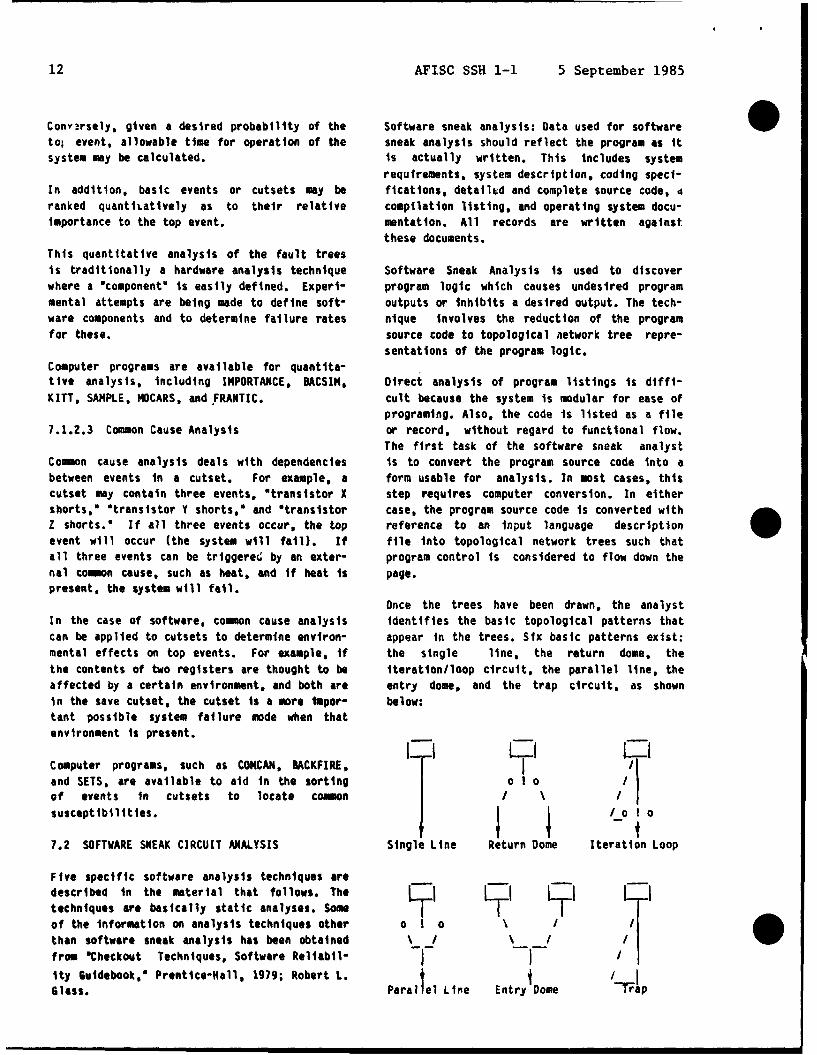
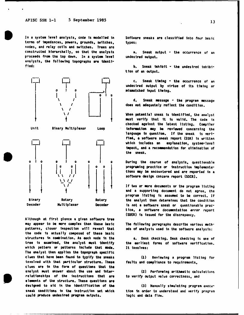
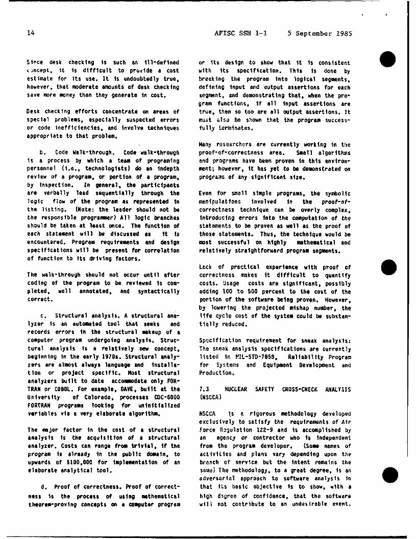
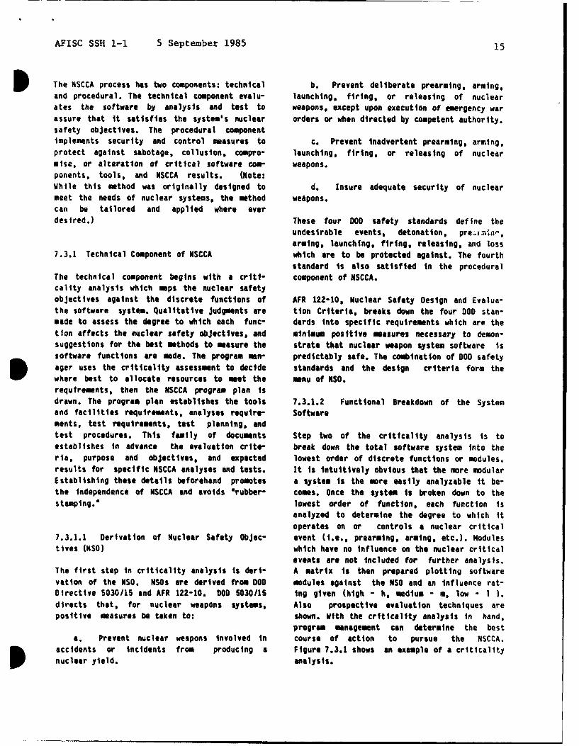
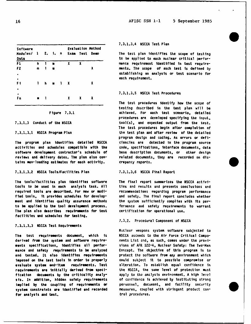
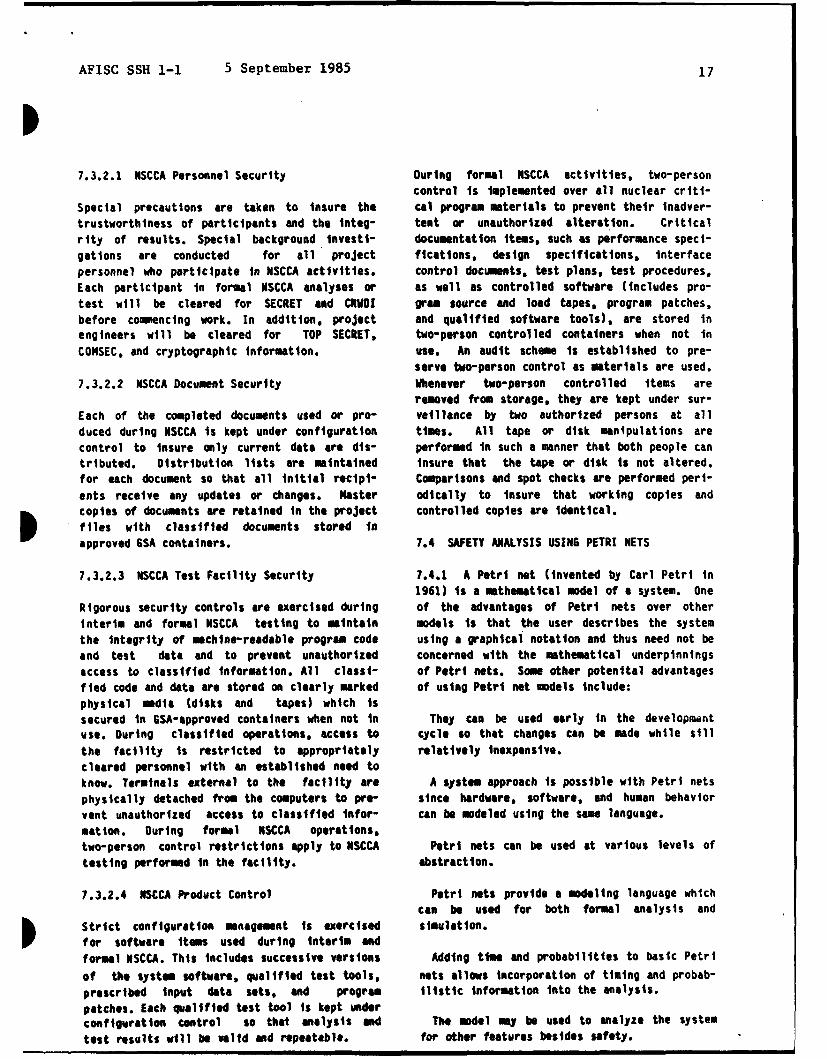
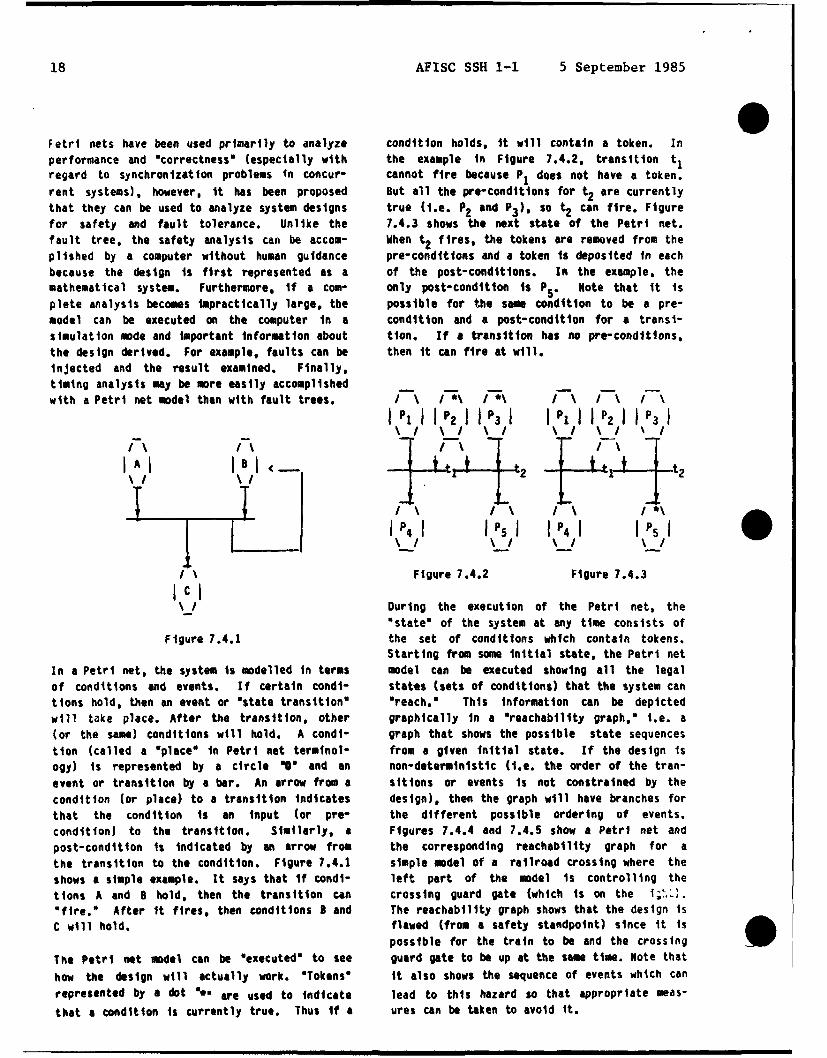
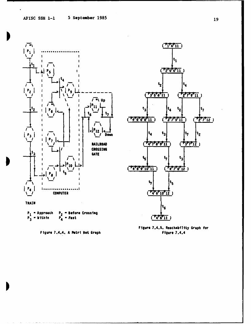
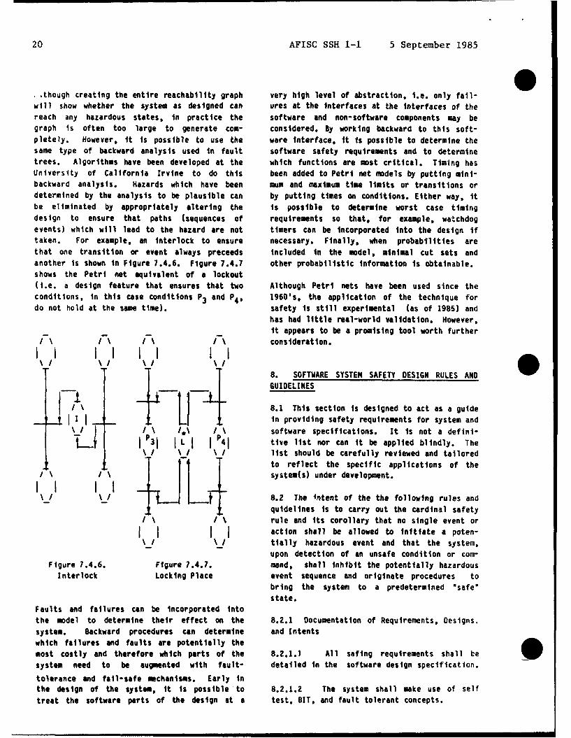


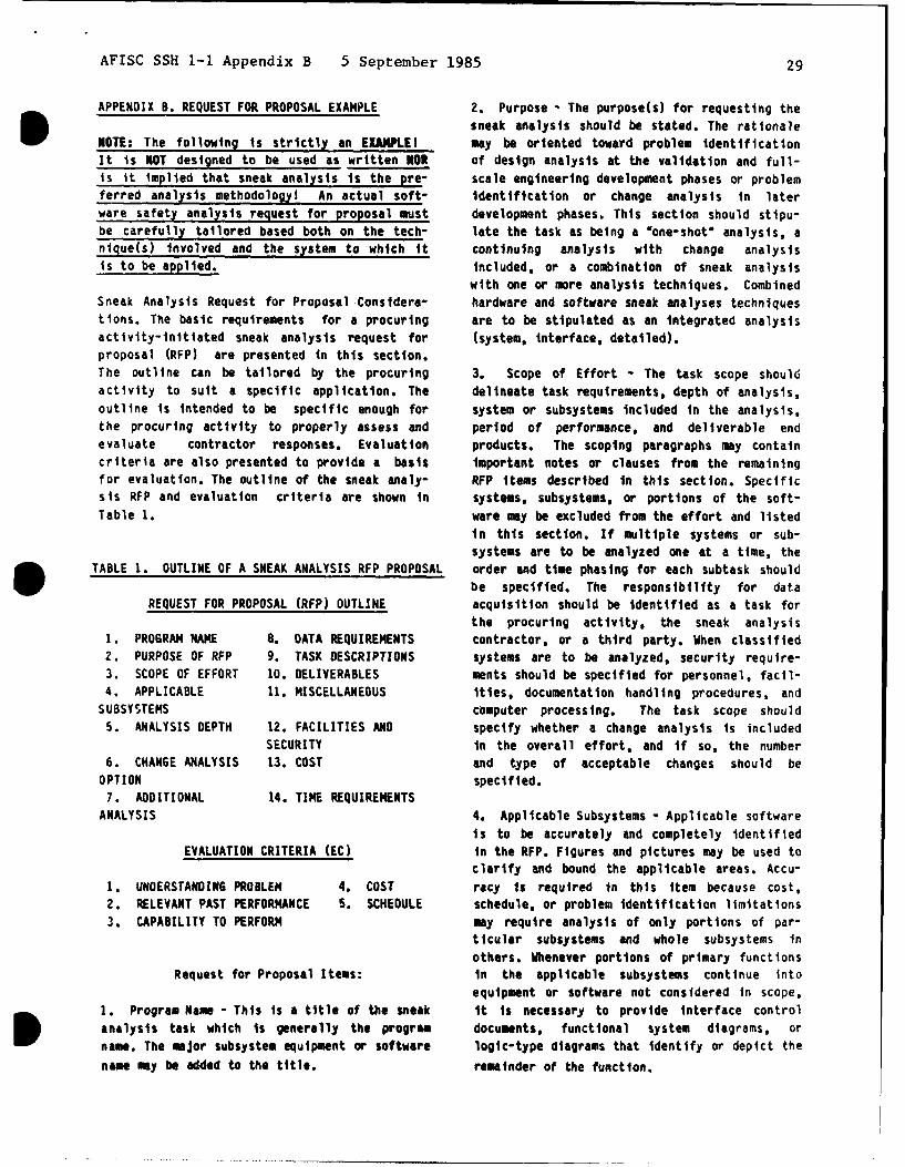


![PL022RD2 DTIC · Logistics Management Institute Using Process Redesign and Information Technology to Improve Procurement PL022RD2 DTIC ELECTE Daniel]. Drake 19951205 061 LMI . REPORT](https://static.documents.pub/doc/80x56/600a77dd5689071bbe315e47/pl022rd2-dtic-logistics-management-institute-using-process-redesign-and-information.jpg)


