USAFSAM-TR-89-35 AD-A226 441 EVALUATION OF THE MODEL 185 AIRBORNE LIFE SUPPORT SYSTEMS INFANT TRANSPORT INCUBATOR Robert J. Van Oss, Technical Sergeant. USAF Rebecca B. Schultz, Second Lieutenant, USAF, BSC Ernest G. Roy, Master Sergeant, USAF DTIC ELECTE S EP 1 3 1990 March 1990 D Final Report for Period April 1988 - October 1988 Approved for public release; distribution is unlimited. 90 09 1 06, USAF SCHOOL OF AEROSPACE MEDICINE Human Systems Division (AFSC) Brooks Air Force Base, TX 78235-5301 .
Transcript
USAFSAM-TR-89-35 AD-A226 441
EVALUATION OF THE MODEL 185 AIRBORNELIFE SUPPORT SYSTEMS INFANT TRANSPORTINCUBATOR
Robert J. Van Oss, Technical Sergeant. USAFRebecca B. Schultz, Second Lieutenant, USAF, BSCErnest G. Roy, Master Sergeant, USAF
DTICELECTES EP 1 3 1990
March 1990 D
Final Report for Period April 1988 - October 1988
Approved for public release; distribution is unlimited.
90 09 1 06,USAF SCHOOL OF AEROSPACE MEDICINEHuman Systems Division (AFSC)Brooks Air Force Base, TX 78235-5301 .
NOTICES
This final report was submitted by personnel of the Chemical Defense Branch, CrewTechnology Division, USAF School of Aerospace Medicine, Human Systems Division, AFSC,Brooks Air Force Base, Texas, under job brder 7930-16-12.
This report was prepared as an account of work sponsored by an agency of the UnitedStates Government. Neither the United States Government nor any agency thereof, nor any oftheir employees, nor any of their contractors, subcontractors, or their employees, makes anyvarranty, expressed or implied, or assumes any legal liability or responsibility for the accuracy,completeness, or usefulness of any information, apparatus, product, or process disclosed, orrepresents that its use would not infringe privately owned rights. Reference herein to any specificcommercial product, process, or service by trade name, trademark, manufacturer, or otherwise,does not necessarily constitute or imply its endorsement, recommendation, or favoring by theUnited States Government or any agency, contractor, or subcontractor thereof. The views andopinions of the authors expressed herein do not necessarily state or reflect those of the UnitedStates Government or any agency, contractor, or subcontractor thereof.
When Government drawings, specifications, or other data are used for any purpose otherthan in connection with a definitely Government-related procurement, the United StatesGovernment incurs no responsibility or any obligation whatsoever. The fact that the Governmentmay have formulated or in any way supplied the said drawings, specifications, or other data, is notto be regarded by implication, or otherwise in any manner construed, as licensing the holder or anyother person or corporation; or as conveying any rights or permission to manufacture, use, or sellany patented invention that may in any way be related thereto.
The Office of Public Affairs has reviewed this report, and it is releasable to the NationalTechnical Information Service, where it will be available to the general public, including foreignnationals.
This report has been reviewed and is approved for publication.
JE D. JENS , Major, USAF, NC F. WE SIY BAUMGARDNER, Ph.D.Project Scientist Superv' or
6a. NAME OF PERFORMING ORGANIZATION 6b. OFFICE SYMBOL 7a. NAME OF MONITORING ORGANIZATIONUSAF School of Aerospace I (if appicabit)Medicine I t1SAFSAN/VNC
6c ADDRESS (City, State, and ZIP Code) 7b ADDRESS (City, State, arnd ZIP Code)
Human Systems Division (AFSC)Brooks AFB, TX 78235-5301
S.. NAME OF FUNDING /SPONSORING 8 b. OFFICE SYMBOL 9 PROCUREMENT INSTRUMENT IDENTIFICATION NUMBERORGANIZATION USAF School of (I applicable)
Aerosnace Medicine IUSAFSAMI/VNC __________________________
Ot. ADDRESS (City, State, and ZIP Code) 10. SOURCE OF FUNDING NUMBERSPROGRAM PROJECT TASK WORK uNIT
Human Systems Division (AFSC) ELEMENT NO NO. NO ACCESSION NOBrooks AFB, TX 78235-5301 6-220)2F 7930) lb 1)
11. TITLE (include Security Oassfication)Evaluation of the Model 185 Airborne Life Support SVystemsl,- 111IL ab t ra-.port Incubat or
12. PERSONAL AUTHOR(S)Van Oss, Robert J.; Schultz, Rebecca B.; Roy,f Ernest GI.
13a. TYPE OF REPORT 13b. TIME COVERED 14. DATE OF REPORT (Year, Month, a)I PAECOUNT
Final IFROM 88104 TO 88/10 1990, Mairchl 7 30
16. SUPPLEMENTARY NOTATION
17. COSATI CODES 1SUBJECT TERMS;on- v -- sm-4 mete y, e, do b
FIELD GROUP SUB-GRt UP Acromedical evacuiat ion; Incubator; humidification;
.201 Airboruc Life Support Svstems. 4 K
1ABSTRACT (Continue n reverie if necestry and identify by block number)
he Military Airlift Command (NAC) is the rentral manager for aeromedicn] evacuat ion in the0Department of Defense. The safe'evacuation of infants in MAC aircraft has alwaiys heen nnimportant concern because infants must be transported in a controlled environment. The Ohio
Transport Incubator, now in use, is no longer manufactured. If an Ohio inCuibator breaksdown, needed spare parts nay not be available. The Model 185 Airborne Life Support Systemis(ALSS) infant transport incubator has been s eted to replace the Oh1io ilneuhator in theU.S. Air Force (USAF) inventory. Now available or use, thle Al.SS is lighter thlan the Ohbio;it has an internal humidification system, an inte r I batterv, and a digital temperaturereadout. The Aeromedical Equipment Evaluation La bor~ ory at the USAF School of AerospaceMedicine tested the ALSS incubator and found it to be safe, adequate device for transport-ing an infant without jeopardizing the infant's heal th.
20. DISTRIBUTION/ AVAILAILITY OF ABSTRACT 21 ABSTRACT SECURITY CLASSIFICATION~UNCLASSIFIE D/UNLI MITED f17 SAME AS RPT. C DTIC USERS Unclassified
22a. NAME OF RESPONSIBLE INDIVIDUAL Z2b:.TELEPHONE (Include Area od)22c OFFICE SYMBOLrq D 1qn ao.UAF.N 512 536-2937 USAFSAM/VNC
00 Form 1473, JUN 86 Previous editions are obsolete. SECURITY CLASSIFICATION OF TWIS PAGE
D E S C R IP T IO N ..................................................................................................................... 1
M ET H O D S ............................................................................................................................ 3Baseline Performance Assessment ...................................................... 4
Human Factors and Physical Characteristics ...................... 4W arm-Up Time .................................................................................. 4Temperature Accuracy and Uniformity .................................... 5Electrical Safety .................................................................................... 5Battery Operation/Charging Characteristics ...................... 5Extended Operation on 110 VAC/400 Hz ................................ 5T ilt T e st ............................................................................................ . . 5Interior Sound and Light Levels ....................................................... 5
V ib ra tio n ................................................................................................................ 6Environmental ................................................................................................ 8
High Temperature ............................................................................ 8Low Temperature .............................................................................. 8Humidity .............................................................................................. 85% Humidity ........................................................................................ 8Direct Sunlight Exposure .............................................................. 8
A ltitu d e .................................................................................................................. 9Decompression ............................................................................................. 9Fresh Air Flow .............................................................................................. 9
R E S U LT S ........................................................................................................................... 1 0Baseline Performance Assessment ................................................... 10
Human Factors and Physical Characteristics ................... 10Warmup Time .................................................................................. 10Temperature Accuracy and Uniformity .................................. 1 0Electrical Safety .......................................................................... 11Battery Operation and Charging Characteristics ............ 11
i i i
Extended Operation on 110 VAC/400 Hz .................................. 1 1Tilt Test .................................................................................................... 11Interior Sound and Light M easurem ents .................................. 1 1
FIGURES1. Probe placem ent ............................................................................................. 32. X and Y axis vibration test ........................................................................... 73. Z axis vibration test ....................................................................................... 74. Hot operation test .......................................................................................... 1 35. Cold operation test ....................................................................................... 1 46. Humidity performance in a 5% RH environment .............................. 1 47. Direct sunlight exposure; no cover ......................................................... 1 68. D irect sunlight exposure; with cover .................................................... 1 69. Altitude test ...................................................................................................... 17
EVALUATION OF THE MODEL 185AIRBORNE LIFE SUPPORT SYSTEMS
INFANT TRANSPORT INCUBATOR
BACKGROUND
Military Airlift Command (MAC) controls aeromedical evacuation (AE) missions forthe United States Air Force (USAF). There has always been a need for a means tosafely transport infants in a controlled environment within the AE arena. The OHIOTransport Incubator, currently in use, is no longer manufactured; consequently, thereis a shortage in spare parts to repair those incubators still being used. The Model185 Airborne Life Support Systems (ALSS) is the selected AE replacementincubator. This incubator is lighter than the OHIO and has an internal battery, adigital display (light emitting diode [LED]) temperature readout, and an internalhumidification system. It is now available for use.
DESCRIPTION
During AE missions, the ALSS 185 Infant Transport Incubator supports an infant'sthermal need in flight by circulating warmed, humidified air through the infantchamber.
The incubator dimensions are: height, 50.8 cm (20 in.); width, 101.6 cm (40 in.);depth, 55.9 cm (22 in.); and weight, 36.3 kg (80 Ib). The infant chamber is enclosedin a clear Plexiglas double-walled hood. The mattress tray dimensions are 30.5 x 61x 1.9 cm (12 x 24 x 3/4 in.). The rectangular mattress, slightly smaller than the tray,is a spongy foam material covered by a plastic outer shell. The infant chamber has aminimum vertical clearance of 22.9 cm (9 in.). There is a front access door with twohand ports 20.3 x 56.5 cm (8 x 22 1/4 in.), a standard size head access door, and twostandard size tubing ports. Mounted to the incubator frame is a flexible 5-wattexamination light. On the aft face of the unit an intravenous (IV) pole is secured witha well and lock pin. There is space for securing two "D" or two "E" size oxygencylinders. The incubator has carrying handles on both ends with two securingdevices. These securing devices are used to safely secure the incubator to astandard North Atlantic Treaty Organization (NATO) litter which is placed in thesecuring stanchions of the aircraft.
A two position rocker switch is used to turn the incubator power on and off. Theinfant chamber temperature is controlled by a thumb wheel rheostat located on thelower right corner of the front face of the incubator. Next to the thumbwheel control isan LED display ranging from 30.0-39.9 0C (87.6 - 103.8 OF). The operator uses thethumbwheel to increase or decrease the incubator temperature in 0.1 0 C increments.There are two external ports on the front face of the incubator to control thehumidification system. Using these ports, the operator can add or remove water froma sponge located in a compartment below the mattress tray without disturbing theinfant or changing the internal incubator temperature. Heated air inside the incubatoris humidified as it circulates across the sponge.
1
The unit can operate from an external power source of 115 volts alternating current(VAC) 50 to 400 hertz (Hz), 12 to 14.5 VDC, or from an internally mounted 12V/24ampere hour (AH) sealed lead/acid rechargeable battery. When the incubator isconnected to an AC source and the power switch is on, the AC operation mode isautomatically selected and the AC operation (OP) indicator is illuminated. Batteryoperation is automatic when the power switch is turned on and no external power isapplied. The battery (BAT) OPERATION indicator illuminates in this mode. External12 VDC operation is automatic when applying external DC power and switching onthe power switch. The DC OPERATION indicator illuminates to reflect external 12VDC operation. Connecting AC power will supersede external DC operation.
Illumination of the LOW BATTERY indicator, accompanied by an intermittentaudible alarm, indicates battery voltage is less than 11 VDC. The incubator will beable to supply the heater requirements for only a few minutes in the low batteryoperation mode. The LOW BATTERY alarm is non-resettable. The POWER FAILindicator activates when the battery falls below 10 VDC, indicating that the batteryhas reached its safe discharge limit, and power to maintain the temperature in theinfant chamber is no longer available. All power to the incubator, other than for thisindicator and audible alarm, is disabled.
The HIGH TEMP alarm indicator, accompanied by an intermittent audible alarm, istriggered when the temperature of the primary sensor exceeds 38.5 OC (101.3 OF).The HIGH TEMP and SYSTEM FAIL alarms, coupled with a continuous audible alarm,indicate that the primary temperature sensor is over 39.0 °C (102.2 OF). Theincubators heater system is disabled and the incubator will cool to below 39.0 0C(102.2 OF) before re-energizing the heating system. The SYSTEM FAIL alarm alone,coupled with a continuouj audible alarm, indicates that the secondary (backup)temperature sensor subsystem is reading over 39.2 °C (102.6 OF). The incubatorsheater system is again disabled and the incubator will cool to below 39.2 OC (102.6 IF)before re-energizing this subsystem. The activation of this subsystem alarm indicatesa problem with either the temperature sensors or with the control circuitry. Thiscondition indicates a need for incubator service by qualified personnel.
The AIRFLOW alarm, coupled with a continuous audible alarm, indicates thatthere is an airflow blockage by some object, such as a blanket. The incubatorsheater system is disabled and the incubator will cool until the thermal switch on theheater element drops below its selected temperature. After the airflow is restored andthe heating element has cooled, the heater system will return to normal operation.The SENSOR FAIL alarm, coupled with a continuous audible alarm, indicates that thetemperature being sensed by the primary temperature sensor subsystem is welloutside the normal operational range of the incubator. The activation of thisalarm indicates a problem with the temperature sensor or with thecontrol circuitry, and a need for service by qualified personnel. AnIndicator Test Switch, located on the operation panel, is used to test the LED on thedisplay panel and the audible alarm.
2
METHODS
The Aeromedical Equipment Evaluation Laboratory (AEEL) Procedures Guide (1),an internal document, prescribes which tests are performed and provides aquantitative description of those tests. Not every piece of equipment we evaluateundergoes each and every test. Also, since every piece of equipment is different andunique, not every piece of equipment will be tested in the exact same way.
T1 T2 T30 0 0
G1, G2, H1
Figure 1. Probe placement.
1. Temperature Sensors (10.2 cm (4 in.) above the mattress)
a. T1 (Head) -Centered and 5.1 cm (2 in.) in from the incubator wall
b. T2 (Middle) - Centered within the incubator
c. T3 (Foot) -Centered and 5.1 cm (2 in.) in from the incubator wall
d. T4 (Ambient) - Outside the incubator monitoring room or chamber
2. Humidity Probe
a. H1 - Centered within the incubator and 10.2 cm (4 in.) above themattress
b. H2 - Outside the incubator monitoring room or chamber
3. Gas Measurement
a. G1 (Oxygen) - During actual usage the placement of the oxygen sensor is 5.1 cm(2 in.) from the infant's airway. To approximate this position, we placed the gasanalyzer 11.4 cm (4.5 in.) from the front access door and 20.3 cm (8 in.) from theincubator wall (head). Measurements within the electrical compartment were madecentered within the compartment.
b. G2 (Carbon Dioxide) - Measurements were made at the same location as theoxygen sensor within the incubator. Carbon dioxide flow was administered at thecenter of the incubator compartment.
3
The tests described in this section simulate the environment under which thedevice must function, but under controlled laboratory conditions. We approximatefield conditions as closely as possible for a limited time. The tests vary only oneparameter at a time. Comparison to baseline measurements enables us to assessthat parameters effect on the item. The precise setup used to test the item isdetermined by the Project Coordinator (PC).
Data are collected by computer whenever possible to simplify data plotting andanalysis. If data recording cannot be done by computer, the data are manuallyrecorded on a "Data Collection Sheet." Information specifically relating to the testsetup is recorded for each test on a "Test Information Sheet."
Figure 1 illustrates the location of the test probes: temperature, oxygen, carbondioxide, and humidity. Ambient temperature was monitored during all tests. Theinfant chamber temperatures were measured at three locations across the infantmattress; each centered from front to back and 10.2 cm (4 in.) above the mattress; thehead and foot probes were 5.1 cm (2 in.) in from the left and right Plexiglas walls; themiddle probe was centered above the mattress. Power transformer temperaturemeasurements were made by taping the temperature probe directly to thetransformer. Grant EU-U-V5 minithermistors and a Grant Squirrel Model 1201Datalogger were used throughout our evaluation. Oxygen and carbon dioxideconcentrations were measured with a Perkin Elmer Model 1100 Medical GasAnalyzer. Oxygen samples were taken at two locations: centered and 10.2 cm (4 in.)above the mattress, and centered in the electronics compartment. Humidity wasmeasured in and outside the incubator using a Grant L-type probe. Measurementsinside the incubator were made centered and 10.2 cm (4 in.) above the mattress.Unless otherwise noted, the incubator was prewarmed to 37 °C (98.6 OF) on 110 VAC/60 Hz prior to each test.
Baseline Performance Assessment
The purpose of the Baseline Performance Assessment (BPA) was to measure andrecord the incubator's performance under standard ambient conditions (22.0±2 °C(71.6±4 °F), 750±10 mmHg barometric pressure, 50 ± 30% relative humidity) prior toadverse testing. The BPA is used as a reference to measure subsequentperformance against, to verify selected manufacturer and contract specifications, andto ensure safe operation and use prior to testing.
Human Factors and Physical Characteristics-- These are observations madethroughout our evaluation. Observations and corrective action are listed in theResults section.
Warm-U Tine -- The time required to warm the incubator to a set temperature of37 °C (98.6 OF) was measured while operating on 110 VAC/60 Hz and 400 Hz.Ambient temperature was approximately 21 °C (69.8 OF) during the 110 VAC/60 Hztest and approximately 24 °C (75.2 OF) during the 110 VAC/400 Hz test.
4
Temperature Accuracy and Uniformity - The incubator's display temperature wascompared to the mid-mattress temperatures to determine the display's accuracy.Temperature uniformity was determined by comparing the displayed temperaturewith all three mattress temperatures. Mattress temperature uniformity was evaluatedduring a 3-h period at standard ambient conditions with the incubator pre-warmed to37 0C (98.6 OF).
Electrical Safety -- Electrical safety testing consisted of ground resistance andleakage current measurements, and a visual examination of the incubator's wiringand strain relief. Ground resistance was measured from the power plug's ground pinto the exposed metal chassis. The leakage current was measured with the power onand off, with all controls adjusted to yield the highest leakage current (unit off), withthe power supply ground intact (normal polarity), with ground lifted (normal polarity),and ground lifted (reverse polarity). All measurements were made using a DempseyModel 431 Safety Analyzer.
Battery Operation/Charging Characteristics -- These tests were performed to verifythe incubator's battery operation time and charging characteristics. Battery operationand charging currents were measured by placing a precision resistor load of 25milliohms in series with the positive battery terminal and calculating the current fromthe resulting voltage drop. Battery voltage was measured across the batteryterminals. Temperatures and voltages were recorded on a Squirrel Datalogger at asample rate of once per minute. The incubator's battery was first discharged until thelow battery light illuminated and then charged for 6 h on 110 VAC/60 Hz. Theincubator was then pre-warmed to 37 °C (98.6 OF) on 110 VAC/60 Hz in accordancewith (lAW) the manufacturer's instructions. It was then disconnected from externalpower and allowed to operate on internal battery until the low battery lightilluminated. This charge and operation cycle was repeated on 110 VAC/400 Hzpower.
Extended Operation on 110 VAC/400 Hz -- Power sources of 110 VAC/400 Hz areunique to the aircraft. To ensure the incubator would safely operate on 110 VAC/400Hz for an extended period, the unit was operated for 36 hours under ambient roomtemperature and humidity. The incubator and power transformer temperatures weremeasured during this period.
Tilt Test -- The incubator is placed in many different angles and axes duringtransport. To test for water leakage from the humidification reservoir into other areasof the incubator, we filled the reservoir with 250 ml (8.4 oz) of water, lAW themanufacturer's literature at that time, and tilted the incubator 450 from front to backand from side to side for a 1-min period. We then examined the incubator's bassinetand electrical compartment for any signs of fluid leakage or component securingproblems; e.g., at the battery, bassinet or cylinder fasteners.
Interior Sound and Light Levels -- Bioenvironmental engineers from the USAFClinic, Brooks AFB, took sound and light measurements using a Gen Rad Model1982 Octave Band Analyzer Sound Meter and a Lite Mate III Model 504 Photometer.Sound level measurements were made at the infant's head location. Lightmeasurements were made as indicated in the Results section.
5
Electromagnetic Compatibility
The purpose of these tests is to verify compliance with MIL-STD-461 C,Electromagnetic Emission and Susceptibility Requirements for the Control ofElectromagnetic Interference, Category Ale (2).
Radiated Emissions (RE-02) -- The RE-02 test measures radiated emissionsgenerated by the incubator. Excessive emissions could interfere with aircraftnavigation and communication equipment. The incubator was tested operating on110 VAC/60 Hz, on 110 VAC/400 Hz, on internal battery, and while charging on 110VAC/400 Hz. Incubator control settings were as follows: with temperature set to37 °C (98.6 IF) with one front port door open to ensure heater circuit remained on,with light on, with Alarm Test button both on and off, with internal battery discharged(low battery LED or;) during AC tests, and with battery fully charged.
Conducted Emissions (CE-03) -- The CE-03 test measures conducted emissionsgenerated by the incubator and conducted back up the power line. Excessiveconducted emissions could affect the aircraft power supply and/or systems poweredfrom it. The incubator was tested operating on 110 VAC/60 Hz, on 110 VAC/400 Hz,and while charging on 110 VAC/400 Hz. Incubator control settings were as follows:temperature set to 37 °C (98.6 OF) with one front port door open, with the light on, andwith the Alarm Test button both on and off.
Radiated Susceptibility (RS-02) -- The RS-02 test determines whether theambient electromagnetic fields encountered in flight interfere with incubatoroperation. The incubator was exposed to the electromagnetic induction fieldsdescribed in the USAFSAM Test and Evaluation Planning Guide for AeromedicalEvacuation Equipment (3). During exposure, the incubator was operated on both110 VAC/60 Hz and battery power while monitoring incubator temperatures andalarm functions.
Conducted Susceptibility (CS-06) -- The CS-06 test verifies that the incubator willsafely operate from the aircraft's noisy fluctuating power supply. Electrical voltagesand waveforms specified in MIL-STD-461 were used. During exposure, while theincubator was operated on both 110 VAC/60 Hz and 110 VAC/400 Hz, incubatortemperatures and alarm functions were monitored.
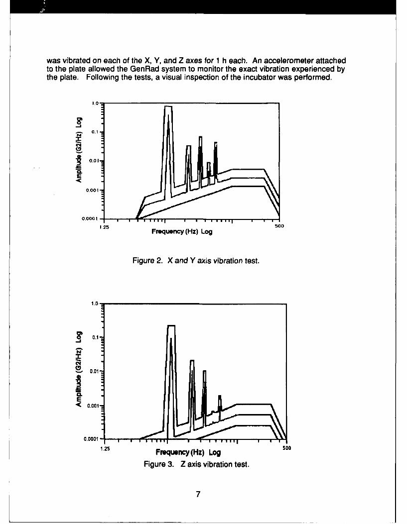
The vibration test, consisting of random and sinusoidal X, Y, and Z curves, tests anitem's construction, durability, and performance during severe vibration. Because ofthe size of the incubator, the vibration table at USAFSAM could not accommodatethis test; consequently, the incubator was taken to the US Army AeromedicalResearch Laboratory (USAARL), Fort Rucker, Alabama, for testing support. TheUSAARL vibration table was used to test the incubator which was strapped to a .95cm (3/8 in.) metal plate that had been bolted to the table. During the test, the tablewas controlled by a GenRad computer system. The vibration curve used, Figures 2and 3, was derived from data collected during a helicopter mission. The incubator
6
was vibrated on each of the X, Y, and Z axes for 1 h each. An accelerometer attachedto the plate allowed the GenRad system to monitor the exact vibration experienced bythe plate. Following the tests, a visual inspection of the incubator was performed.
1.0-
N
0.1
('4
0.01
r! L
E
0.001
0.0001
1.25 Frequency (Hz) Log 500
Figure 2. X and Y axis vibration test.
~0.1
C40.01
E<0.001
0.0001 1 I l i i
1.25 Frequency (Hz) Log50
Figure 3. Z axis vibration test.
7
Enviromeal~
The environmental tests measured the incubator's performance under varyingtemperature and relative humidity (RH) conditions encountered during transport.During each of these tests, except for the storage tests, the incubator was prewarmedto 37 0C (98.6 OF) and placed in an environmental chamber and operated for thespecified period. The incubator was preheated to 37 0C (98.6 OF) and allowed tostabilize for 20 min prior to both operational and storage tests. The incubator wasplaced in the environmental chamber and operated on both line 11OV AC/60 Hz andinternal battery power for the specified periods.
High Temperature --Operation: 49 °C ± 2 0C (120 OF ± 3.6 OF) for 2 h.
Storage: 60 0C 2 0C (140 OF ± 3.6 OF) for 6 h.
Low Temperature--Operation: 0 0C ± 4 °C (32 OF ± 7.20 F) for 2 h.
Storage: -40 0C ± 2 0C (-40 OF ± 3.6 OF) for 6 h.
Humidity --
Operation: 94 ± 4% RH, 29.5 C ± 2 0C (85 OF ± 3 OF), for 4 h.
5% Humidity -- Specifications called for the incubator to maintain 20% RHwithin the infant chamber for 4 h while operating within a 5% RH ambientenvironment. This test was performed using a hypobaric chamber to create a 5% RHenvironment at an equivalent altitude of 3048 m (10,000 ft). With the incubator insidethe chamber, a Grant Model 1201 Data Logger recorded both the interior incubatorhood and the ambient chamber temperatures and RH. One humidity probe wasplaced inside the incubator mid-compartment, elevated approximately 5.1-7.6 cm(2-3 in.) above the mattress. A second humidity probe was positioned outside theincubator approximately 0.30 m (1 ft) away. The temperature was monitored insidethe incubator hood mid-compartment, and outside the incubator at the end of theNATO litter. Per manufacturer's recommendations, 150 cm3 of water was injectedinto the incubator's humidification system. The Data Logger sampled humidity andtemperature levels every minute. Occasionally, throughout the test, an attempt wasmade to extract excess water from the humidification system's drain port.
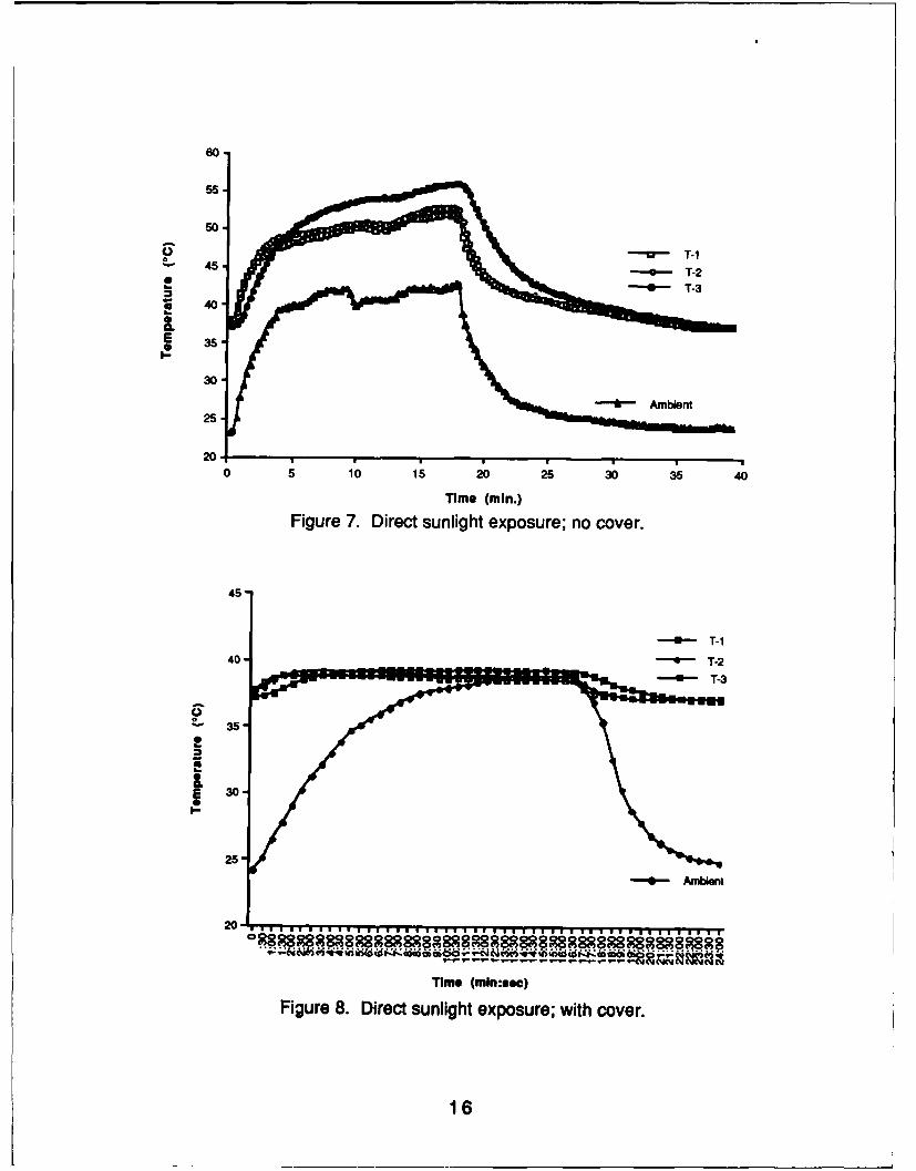
Direct Sunlight Exposure -- This test was conducted to determine the effects ofdirect sunlight on the clear Plexiglas hood assembly. The unit was prewarmed to37 0C (98.6 F) and exposed to direct sunlight while the Grant Data Logger monitoredthe incubator's infant chamber temperature at three locations, and the ambienttemperature outside the incubator 0.30 m (1 ft) from the incubator. Sample readingswere taken every 15 sec to observe the rapid temperature increase.
In a second test, the effect of shading the incubator hood area from the sun wasexamined. The test setup and environmental exposure was the same as for the firstsunlight test. A standard white hospital bedsheet was folded in half and folded in halfagain, and placed over the Plexiglas hood. Following both tests, the incubator wastaken indoors and allowed to stabilize at 37 0C (98.6 °F).
8
Alitude
We subjected the incubator to reduced atmospheric pressures of 564 mmHg, 2440m (8,000 ft) equivalent, for a 30-min period on battery power.
Decompression
Decompressions are uncommon; however, if one were to occur, the incubatorshould not present a hazard to the infant, to the crew, or to aircraft operations. In thehypobaric chamber the incubator, operating at an equivalent cabin pressure of 2438m (8,000 ft), was subjected to a series of three sudden decompressions to 12,190 m(40,000 ft) equivalent pressure in 1, 7, and 60 sec.
FesAlow
Air exchange within the infant chamber is a concern since an excessive buildupof carbon dioxide (P02) or oxygen (02) could worsen the condition of the child in theincubator.
Carbon Dioxide Concentration -- Fresh air flow through the incubator must besufficient to prevent a buildup of C02. The maximum safe concentration of C02, asspecified in the contract, is 0.5%. Thirty cc/min of C02* was injected into the infantchamber of the incubator that had been prewarmed to 37 °C (98.6 OF). The C02concentration inside the infant chamber and the ambient concentration outside theincubator were monitored using the Perkin Elmer Model 1100 Medical Gas Analyzer.
Oxygen Concentration -- Maximum oxygen concentrations which could bemaintained within the incubator at various oxygen flow rates were evaluated at anequivalent altitude of 3048 m (10,000 ft) in the hypobaric chamber. Oxygen wasducted into the prewarmed incubator through a flowmeter. A Biomarine OxygenAnalyzer measured the 02 concentration inside the infant chamber at flow rates of1, 2, 3, 4, 5, 6, 7, 10, and 15 liters per minute. The 02 concentration at each flow ratewas recorded.
In-Flight Feasibility
Two Aeromedical Research Technicians assigned to USAFSAM/VN performedthe in-flight feasibility test in C-9, C-12, C-21, C-130, and C-141 aircraft and in UH-1,and H-60 helicopters. The purpose of in-flight testing was to evaluate the incubatorscompatibility with each airframe, to verify that it was operationally sound, and to verifyits structural ability to withstand the vibrations encountered during actual takeoff, in
As suggested by the AAMI Draft Standard for Infant Incubators (May 1984).
9
flight, and during landing. The incubator was operated according to manufacturersspecifications for actual use. During each flight, the AE technicians measuredambient and incubator temperatures every 15 min both manually and using a GrantSquirrel Model 1201 Datalogger with Grant Type EU-U-V5 mini-thermistors. Relativehumidity was recorded every 15 min on the C-141 mission, using a Hygrotest Model6400 temperature/humidity probe. Decibel noise levels inside the incubator hoodand within the aircraft cabin were measured every 15 min using Metrosonics SoundLevel Analyzers Model dB-310. Ambient humidity levels within the aircraft cabinswere measured with a Princo Humidity System (swing type) with slide conversionruler. Following each mission the data derived from the evaluations were transferredto a Z-1 84 laptop computer. Other medical crewmembers on each mission wereencouraged to help with on/off loading procedures, to help secure equipmentonboard the aircraft, and to ask questions about the incubator, thereby providing userfeedback.
RESULTS
Baseline Performance Assessment
Human Factors and Physical Characteristics -- The securing mount originallyfailed to safely secure the incubator to a NATO litter. The bulkiness and roundededges of the incubator in combination with tilting the litter during loading caused theincubator to partially slide off the litter. The straps and metal hooks provided with theunit did prevent the incubator from totally falling off the litter. Nevertheless, the litterwas very awkward and unstable to carry. The manufacturer later modified the mount,placing an additional aluminum ridge on each side of the existing mount whichprevented slippage when carrying.
Several glued-on rubber feet, separating the hood's double wall construction, felloff during normal use. The manufacturer later added Plexiglas extensions to theinternal wall construction eliminating the need for rubber feet. No secure storage orvertical securing mechanism was provided with the IV pole. A twistlock and spring-loaded locking mechanism was added later to prevent vertical dislodging during use.A securing mechanism was also added to prevent IV pole movement in the storageposition.
Warmup Time -- The incubator warmup time to 37 °C (98.6 OF) was 16 min on 110VAC/60 Hz and 8 min on 110 VAC/400 Hz. Differences in warmup times wereattributed to the difference in ambient temperatures between the two tests. Theambient temperature was approximately 21 °C (70 OF) during the 110 VAC/60 Hz testand approximately 24 0C (75 OF) during the 110 VAC/400 Hz test. The warmup timeswere within the limits specified in the contract (no more than 20 min). Note that themanufacturers operating instructions specifies a 20-min stabilization period at theselected temperature before placing the infant into the incubator.
Temperature Accuracy and Uniformity - Accuracy of the incubators displaytemperature was within the limits specified in the contract, ±1 °C (2 OF) from theincubators set temperature at an ambient temperature of 22.77 °C (73 OF), and the
10
manufacturers specification, ± 0.5 0C (1 OF) for display accuracy. It should be notedthat during the incubator warmup period and during rapid extreme temperaturechanges the temperature accuracy and uniformity may exceed 1 OC (2 OF). However,this is an expected and an inherent characteristic of incubator heating systems whichuse heated circulating air. Example: The Ohio Transport Incubator currently in usehas temperature variations greater then 100 F when exposed to environmentalchanges, i.e., 4.4 °C (40 OF), 22.7 OC (73 OF).
Electrical Safety -- The electrical safety check consisted of ground resistance andleakage current measurements as well as a visual inspection of the incubators wiringand strain relief. Measured ground resistance from the ground pin of the power plugto the exposed chassis was 120 mQ. Maximum chassis leakage current was 16 pA.During disassembly, the battery lead wire's insulation frayed causing arcing betweenthe exposed wire and the metal chassis. The wire's insulation was so thin it could beeasily scraped off with fingernail pressure. The manufacturer later increased theinsulation factor to its Underwriter Laboratory (UL) rating.
Battery Operation and Charging Characteristics -- Battery operation time was3.7 h, after a 6-h battery charge on 110 VAC/60 Hz and 3.45 h, after a 6-h batterycharge on 110 VAC/400 Hz. These battery operation/charge times were within thecontract specifications (minimum 2-h operation, 24-h charge time) and themanufacturers specifications (nominal 3-h operation, 6-h charge time).
Extended Operation on 110 VAC/400 Hz -- The incubator was operated for 36continuous hours on 110 VAC/400 Hz. No excessive transformer temperatures oroperational problems were noted.
ilt Test -- Approximately 60 cm3 of water overflowed from the reservoir past theheating pad, power switching transistor (Q-5), and into the air circulating fan when theincubator was tilted 450. Fluid leaked around Q-5 and onto its soldered leadconnections. Water within the circulating fan area did not leak into the motor orelectronics beneath. The manufacturer resolved the problem by reducing therecommended reservoir volume from 250 to 150 cm3 and using insulating sealantaround 0-5. After making these changes, we repeated the tilt test with no water leaksnoted. According to the incubator manufacturer, the chance of electrical hazardscaused by water leaks is remote and has never been reported by customers overyears of use. To further minimize the hazard, we recommend clearly identifying thesponge specifications within the operation manual. A sponge which is too thick mayalter airflow and temperature characteristics; a sponge which is too small or using nosponge will increase the probability of fluid leakage from the reservoir.
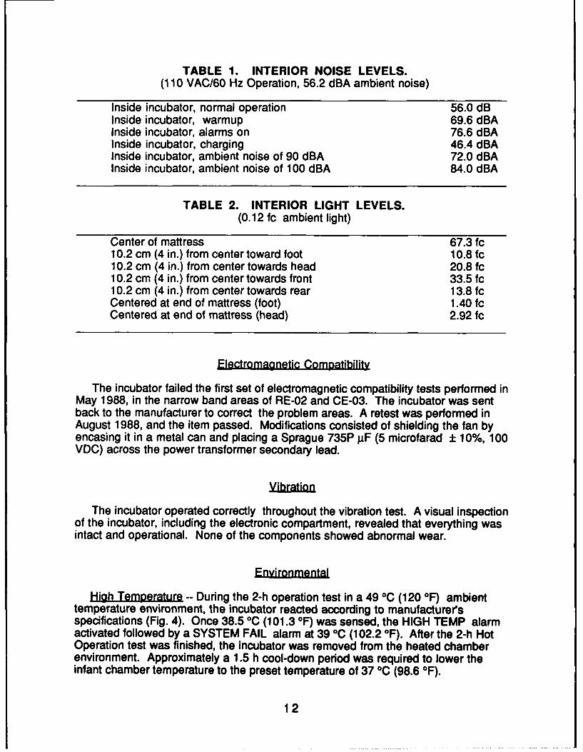
Interior Sound and Light Measurements -- Sound measurements were below the60 dBA specified in the contract under normal operation. Other noise levels arepresented in Table 1 for information only. Light illumination levels, shown in Table 2,are within the contract limits of 30 fc at mattress level. However, illumination intensityvaries considerably across the mattress.
Inside incubator, normal operation 56.0 dBInside incubator, warmup 69.6 dBAInside incubator, alarms on 76.6 dBAInside incubator, charging 46.4 dBAInside incubator, ambient noise of 90 dBA 72.0 dBAInside incubator, ambient noise of 100 dBA 84.0 dBA
TABLE 2. INTERIOR LIGHT LEVELS.(0.12 fc ambient light)
Center of mattress 67.3 fc10.2 cm (4 in.) from center toward foot 10.8 fc10.2 cm (4 in.) from center towards head 20.8 fc10.2 cm (4 in.) from center towards front 33.5 fc10.2 cm (4 in.) from center towards rear 13.8 fcCentered at end of mattress (foot) 1.40 fcCentered at end of mattress (head) 2.92 fc
Electromagnetic Compatibility
The incubator failed the first set of electromagnetic compatibility tests performed inMay 1988, in the narrow band areas of RE-02 and CE-03. The incubator was sentback to the manufacturer to correct the problem areas. A retest was performed inAugust 1988, and the item passed. Modifications consisted of shielding the fan byencasing it in a metal can and placing a Sprague 735P I±F (5 microfarad ± 10%, 100VDC) across the power transformer secondary lead.
The incubator operated correctly throughout the vibration test. A visual inspectionof the incubator, including the electronic compartment, revealed that everything wasintact and operational. None of the components showed abnormal wear.
Enonmeal
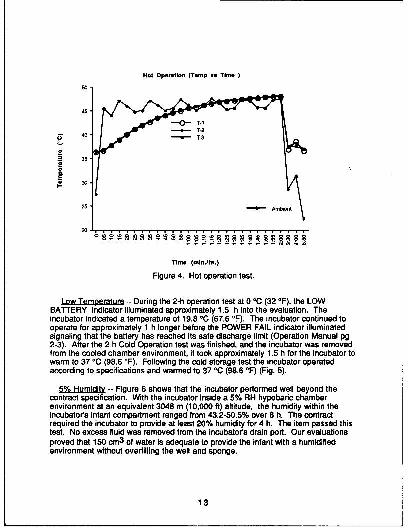
High Temperature -- During the 2-h operation test in a 49 °C (120 OF) ambienttemperature environment, the incubator reacted according to manufacturer'sspecifications (Fig. 4). Once 38.5 OC (101.3 OF) was sensed, the HIGH TEMP alarmactivated followed by a SYSTEM FAIL alarm at 39 OC (102.2 OF). After the 2-h HotOperation test was finished, the incubator was removed from the heated chamberenvironment. Approximately a 1.5 h cool-down period was required to lower theinfant chamber temperature to the preset temperature of 37 °C (98.6 OF).
12
Hot Operation (Temp vs Time )
50
45
40 T-2
0
_ 35
E* 30I-
25 - 0 Ambient
200 wn 0n La 0; U1 0000
Time (mln./hr.)
Figure 4. Hot operation test.
Low Temperature -- During the 2-h operation test at 0 °C (32 °F), the LOWBATTERY indicator illuminated approximately 1.5 h into the evaluation. Theincubator indicated a temperature of 19.8 °C (67.6 OF). The incubator continued tooperate for approximately 1 h longer before the POWER FAIL indicator illuminatedsignaling that the battery has reached its safe discharge limit (Operation Manual pg2-3). After the 2 h Cold Operation test was finished, and the incubator was removedfrom the cooled chamber environment, it took approximately 1.5 h for the incubator towarm to 37 °C (98.6 OF). Following the cold storage test the incubator operatedaccording to specifications and warmed to 37 °C (98.6 OF) (Fig. 5).
5Humidity -- Figure 6 shows that the incubator performed well beyond thecontract specification. With the incubator inside a 5% RH hypobaric chamberenvironment at an equivalent 3048 m (10,000 ft) altitude, the humidity within theincubator's infant compartment ranged from 43.2-50.5% over 8 h. The contractrequired the incubator to provide at least 20% humidity for 4 h. The item passed thistest. No excess fluid was removed from the incubators drain port. Our evaluationsproved that 150 cm3 of water is adequate to provide the infant with a humidifiedenvironment without overfilling the well and sponge.
13
Cold Operation (Temp vs Time)
45-
40 - T-1-4- T-2
35 -- T-3
30
25-
* 20-
g* 15-E
10-
5-
0min
-5-
10
Time (hr:min)
Figure 5. Cold operation test.
Humidity (Levels vs Time)60-
55-
-~ Icubaor Humidity %
45-
.E 40-
.~35-
30-
25-E -00 Sato % Level
15-
10-
0JJC~ '11 11 11 ........... t-r-r m
Time (hr:mln)Figure 6. Humidity performance in a 5% RH environment.
14
Direct Sunlight Exposure -- A sudden temperature rise in the infant chamberoccurs when the incubator is exposed to direct sunlight (Fig. 7). This suddentemperature increase could endanger the infant. Heat injury can be avoided bycovering the clear, double-walled hood with material similar to the white cottonbedsheet used during our test. Shielding the Plexiglas hood keeps the incubator'sinfant chamber temperature below a level of concern, and still keeps the infant inview (Fig. 8).
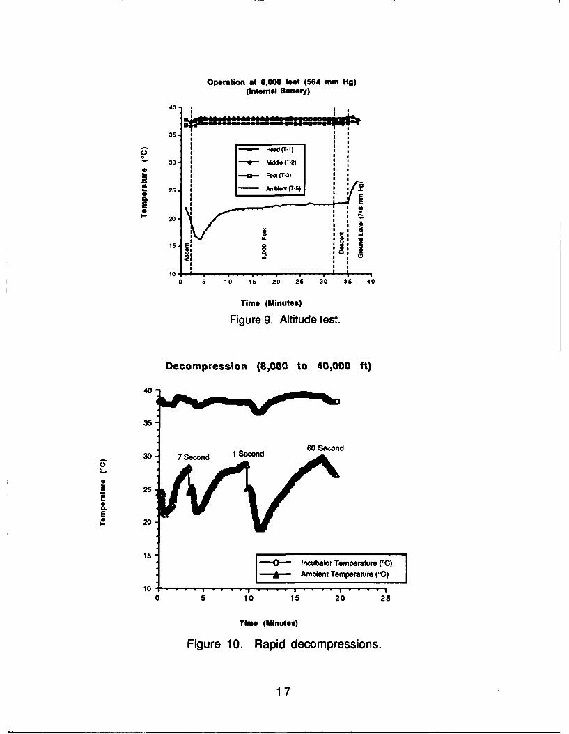
Altitude
At an equivalent altitude of 2438 meters (8,000 ft), infant chamber temperatureswere maintained within 1 0C (2 OF) of the incubators display and set temperatures,Figure 9. No malfunctions were observed during or after the test.
Decompression
Incubator performance during the series of decompressions did not present ahazard to the infant, crew, or chamber operation. Incubator performance wasacceptable and considered normal for operation in such a drastically changingenvironment. Observed temperature changes are illustrated in Figure 10.Immediately after each decompression, the ambient temperature in the hypobaricchamber increased, raising the incubators temperature to 38.5 °C (101.3 OF) andactivating the high temperature alarm. Incubator temperatures continued to increaseand activated the system failure alarm at 39 °C (102.2 OF), turning the heater off. Thehigh temperature alarms operated as expected and prevented temperatures capableof causing hyperthermia. As the hypobaric chamber airflow and temperatureschanged less drastically during normal descent and at ground level, the incubatorstemperature decreased below its selected temperature, turning the heater on.
15
60-
u T-I45-0- T-2
4 T-3S 40-
30-
25
20h
0 5 1"0 15 20 25 0 35 40Q
Time (min.)
Figure 7. Direct sunlight exposure; no cover.
40-
E 30-
25-
- - Ambient
Tim* (mlnmbec)
Figure 8. Direct sunlight exposure; with cover.
16
Operation at 8,000 feet (564 mm Hg)(internal Battery)
40-
35-,
0 30 q (T-2)
• Foot (T-3)
CL
20-. 2 A (T5) I " g
10 .
0 5 10 15 20 25 30 35 40
Time (Minutes)
Figure 9. Altitude test.
Decompression (8,000 to 40,000 ft)
40
35
30 7 Second I Second 6 e;n
25
a.E
20
15 I -a-incubator Temperature (00)I& Ambient Temperture I°C)
10 .. . . . . I . . . ., I . . . . i
05 10 15 20 25
Time (Minutes)
Figure 10. Rapid decompressions.
17
Carbon Dioxide Concentration -- The first time this test was performed at groundlevel, the C02 concentration climbed above 0.5% within the first 10 min. During thefirst 2 h of the test the concentration continued to rise to 0.93%, where it seemed toplateau. For the final 2 h, it remained between 0.93% and 0.99%.
On the original hood, there were three slots along the bottom of the hood to allowfresh air flow, one across the back and one on each side. Working together, one ofour engineers and the contractor found that enlarging the two side slots and closingthe back slot improved removal of C02 without affecting incubator temperature orhumidity. When the test was repeated, the C02 concentration reached a plateau atapproximately 0.27% (Fig. 11).
GL C02 (Levels vs Time)0.6
- Safe C02 Level
0.5
0.4
- Incubator C02 Concentration0.3
0
0.2'
0.1-
-- 1- Ambient C02 Concetmtlion
0.0 T-
Time (hr:mln)
Figure 11. Ground level C02 concentration.
The test was repeated at an equivalent altitude of 3048 m (10,000 ft). During thistest the C02 concentration inside the hypobaric chamber increased, which, in turn,increased the C02 concentration inside the infant chamber. Once the hypobaricchamber was vented with fresh air, both concentrations decreased to an acceptablelevel of 0.29% (Fig. 12).
Oxygen Concentration -- Figure 13 shows the 02 concentration obtained atseveral different flow levels. At 15 liters per minute, the 02 concentration was 85.5%.A maximum 02 concentration of 98% oxygen was obtained at maximum flow (Flush).
18
Altitude C02 (Levels vs Time)0.6-
-U- Safe 002 Concentration Love;
0.5
a Incubator 002 concentration-j 0.4-C
C 0.3.C0
0.0
o~001 --- mbet 0 Concentration
0.1 -T
Time (hr-min)
Figure 12. Altitude C02 concentration.
GL 02 (Levels vs Flow Rats)
100-
* U Ambient 02 Concentrationso E3 Incubator 02 Concentration
C0 70-
S60-C
*40-C
m30-
20
0- 1 2 3 4 5 6 7 10 15
Flow Rate (Liters per min.)
Figure 13. Ground level oxygen concentrations.
19
In-Flight Feasibility
The incubator performed on each of the aircraft lAW the manufacturers descriptionof performance. It secured easily to a standard NATO litter and remained securedthroughout this testing phase. The litter-mounted incubator fit in the stanchions oneach of the selected aircraft with the exception of the H-60 helicopter. Since thehelicopter did not have a medevac carousel installed, the incubator was flownstrapped to the floor of the helicopter using standard aircraft tiedown straps.
During ground transport of the incubator from the hangar to the helicopter, theincubator was exposed to direct sunlight, activating the High Temp alarm. The portson the incubator were opened to release heat since the actual temperature within theincubator exceeded 39.7 °C (103.5 OF). Once we removed the incubator from directsunlight into the helicopter, the temperature returned to 37 °C (98.6 OF), and thesystem operated normally for the remainder of that mission.
Ambient noise levels and noise levels inside the incubator hood assembly wererecorded during the ascent, descent, and in-flight test phases for each aircraft.Environmental impact experts from the USAF Occupational and Environmental HealthLaboratory (OEHL) at Brooks AFB evaluated this data and determined the C-9, C-12,and C-21 average in-flight noise levels inside the incubator did not exceed theEnvironmental Protection Agency (EPA) guideline of 70 decibels (dB) A-weighted (A),calculated over a 24-hour period. The UH-1 helicopter average in-flight noise levelwas slightly above 70 dB (A), but a 19-h exposure would be required to exceed adaily dose of 70 dB (A) if the remainder of that day's exposure were at or below 70 dB(A). The C-130 average in-flight noise levels in the incubator produced the greatestpotential for exceeding the EPA guideline. The C-141 in-flight noise levels inside theincubator varied depending on the 02 flow rate into the incubator, but never exceededthe EPA level of 70 dB (A) except for a short period during taxi. No reliable data werecollected inside the incubator on the H-60 helicopter.
The incubator internal hood temperature was consistently monitored in threeplaces as described earlier in this report. During in-flight feasibility testing, theambient temperature was monitored within 0.61 m (2 ft) of the incubator at the end ofthe litter canvas. The internal temperatures remained fairly constant even though theexterior ambient temperatures varied greatly. The humidification delivery system,along with the incubator's ability to attain varying 02 concentration levels, was testedduring the C-141 mission because of its unique cabin environment and the longflights associated with these missions. The incubator provided adequate humidityand exceeded the requirements specified by the contract. The humidity test wasperformed lAW the manufacturers recommendations for introducing 250 cm3 ofwater into the humidification well. The average level of humidity within the incubatorwas between 60-70% while operating in average ambient environments ranging from<10-80% RH.
During the in-flight Oxygen Concentration feasibility test, oxygen was introducedinto the incubator using the aircraft 02 system and manufacturers recommendedmethod of oxygen therapy. The 02 concentration levels were monitored using theBioMarine Industrias Model OA202R Oxygen Analyzer. The analyzer was affected by
20
aircraft vibration and displayed inaccurate readings. The 02 Concentration Test wasdiscontinued during this phase of testing and conducted back in the controlledlaboratory environment. The incubator passed 02 concentration tests following hoodmodifications to allow the escape of excessive C02 buildup.
CONSIDERATIONS
There is no physical connection between the inner and outer hood. Duringremoval, the inner hood may slip and injure the infant, or may fall to the aircraft flooror onto another patient or crewmember. The infant securing strap metal fastenersmay not adequately restrain an infant during transport. Their small size andconstruction, similar to a paper clip, may present a hazard to the infant if the metalfastener is separated from the strap. The incubator may not be able to accommodatea 4.5 kg (10 Ib) infant safely.
The amount of water needed to provide humidity within the incubator was reducedfrom 250 cm3 to 150 cm3 . We performed the contract required test at the 150 cm3
level and the incubator exceeded the minimum requirements. The operation manualshould be changed accordingly.
USAF OEHL concluded that the noise levels generated by the different aircraft theincubator was tested in did not produce a significant risk to hearing within theincubator due to the relatively short period of exposure. No valid data were collectedon incubator noise levels in the H-60. The OEHL also recommends not taping earplugs over the infant's ear. Currently, there is no commercially available hearingprotection equipment for infants.
When the incubator is exposed to direct sunlight, a sudden rise in the temperaturewithin the infant chamber occurs, as was the case during the in-flight feasibility testphase when the incubator was transported on the ground from a hangar to ahelicopter across a tarmac.
To prevent the sudden rise in temperature inside the preheated incubator'subjected to direct sunlight exposure, we recommend shielding the clear Plexiglashood assembly from the sun's rays. We tested this procedure using a folded whitecotton bed sheet.
To prevent an excessive C02 buildup, the hood assembly was modified byenlarging slots on the two ends of the hood and closing the slot at the back of thehood to allow for ambient air exchange. It is recommended that AE crewmembersrefrain from placing articles that may block the airflow at either end of the hood andincubator tray.
The aforementioned recommended improvement areas were forwarded to the 375AAW/SGNL for action prior to the Operational Testing and Evaluation (OT&E) phaseof the incubator contract. We considered all other items acceptable aftermanufacturer modifications.
21
CONCLUSIONS
Based upon careful analysis of the test results, we* have concluded the ModelALSS 185 Infant Transport Incubator is a safe, adequate means for transporting aninfant without jeopardizing the infant's health. The incubator is acceptable in itsability to produce warmth, maintain humidity, and accommodate oxygen therapy.
FOLLOW-UP
Upon completion of our evaluation, the incubator underwent Operational Testingand Evaluation (OT&E) where it was actually used in the field. When this testing wascompleted, some modifications were made to the incubator based onrecommendations from our testing and from the OT&E. The following changes weremade:
1. The inner and outer hood were permanently connected so they could beremoved as one piece.
2. The wire clips used on the restraining straps were removed. The strapswere widened, and Velcro was used instead of wire.
3. The hood opening was enlarged by 1.27 cm (0.5 in.) in all directions.4. The litter securing straps were modified to better stabilize the incubator on
the litter.5. The examination light was moved from the back center to the back right so
that it could be reached when the incubator was secured in the aircraft.6. The head access door was moved from the left to the right side of the hood
so that, when it was opened the cold air would not affect the thermostatlocated under the left side of the mattress.
7. The one-way valve in the humidity fill port was removed because itprevented adequate cleaning.
8. The power cord length was changed from 1.83 m (6 ft) to 3.1 m (10 ft).
* There is a wide variety of medical backgrounds and knowledge among the members of our group. Wehave a Flight Surgeon (FS), a Flight Nurse (FN), a Biomedical Equipment Maintenance Technician(BEMIT), a Medical Research and Development Technician, three Biomedical Engineers, and twoAeromedical Research Technicians (ART). The FN and ARTs remain current and flight qualified inaeromedical evacuation on the C-9A aircraft. Input is also requested from the 375th Aeromedical AirliftWing (MAC), Aeromedical Equipment Function (SGNL), Scott AFB, IL.
22
ACKNOWLEDGMENTS
We would like to thank those who helped and advised us during the evaluation ofthe ALSS Model 185 Infant Transport Incubator. We would particularly like tothank...
Lt Col John MarshallMaj Mark SwedenburgMaj Garye JensenCapt Terry LewisCapt Sue NagelMSgt Thomas PhilbeckMSgt Rufino NavaltaMSgt John YacalavitchTSgt Gary JenkinsSSgt Thomas WatersMr. John JenkinsMr. Al Lewis
REFERENCES
1. The Aeromedical Equipment Evaluation Laboratory Procedures Guide(Draft). USAF School of Aerospace Medicine, Brooks AFB, January1990.
2. MIL-STD-461C, "Electromagnetic Emission and SusceptibilityRequirements for the Control of Electromagnetic Interference," CategoryAle, August 1986.
3. Test and Evaluation Planning Guide for Aeromedical Equipment. USAFSchool of Aerospace Medicine, Brooks AFB, TX, August 1982.
* U. S. GOVEIRNNT PRINTING OFFICZ: 1990--761-051/20110