32
EEAE 239 Analog Electronics [Lecture 2: Diodes]
| Date post: | 22-Dec-2015 |
| Category: |
Documents |
| Upload: | alim-sultangazin |
| View: | 220 times |
| Download: | 0 times |

EEAE 239 Analog Electronics
![Lecture 2: Diodes]

Analog Electronics - Diodes - Daniele Tosi
pn junctionp-type (positive)n-type (negative)
Majority carriersElectron Hole
Analog Electronics - Diodes - Daniele Tosi
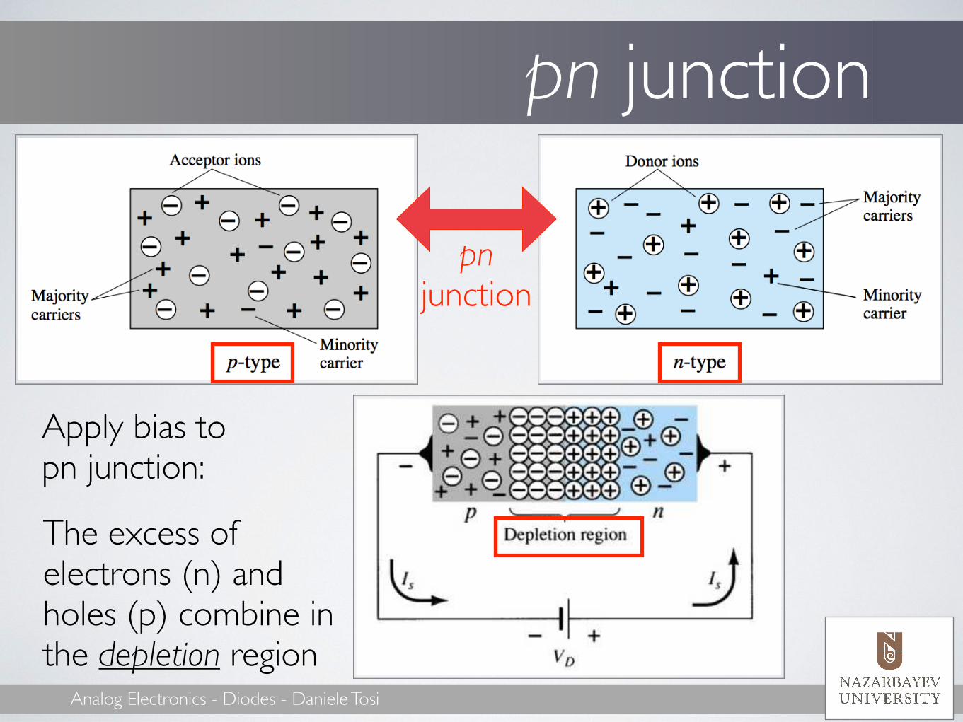
pn junction
pn junction
Apply bias to pn junction:
The excess of electrons (n) and holes (p) combine in the depletion region

Analog Electronics - Diodes - Daniele Tosi
(1) No bias
If 0V voltage is applied to pn junction: - Minority carriers (holes in p) pass
in n material - Majority carriers (electrons in n)
contrast the effect of minority carriers
- The net effect is ~0
The width of the depletion region determines the “resistance” of the diode to conducing current
In no-bias condition, the current through a diode is ~0

Analog Electronics - Diodes - Daniele Tosi
(2) Reverse bias
If negative voltage is applied to pn junction: - The barrier through conductance
increases: the majority current is ~0 - The minority current is the
dominant term, but is a very small term (uA-pA)
When VD<0V: The width of depletion increases
In reverse bias condition, the diode has a small negative saturation current (Is)

Analog Electronics - Diodes - Daniele Tosi
(3) Forward bias
If positive voltage is applied to pn junction: - The majority current overcomes
the effect of the minority carriers - Current flow from p to n - Barrier to conductance abated
When VD>0V: The width of depletion lowers
In forward bias condition, the diode has a large forward current (ID)

Analog Electronics - Diodes - Daniele Tosi
Shockley’s equationSolid state physics: Shockley’s equation
IS: Reverse saturation current (few pA) n: Ideality factor (~1-2) VT: Thermal voltage: VT = kT/q ≅ 26 mV at 27°C (300K) (k = Boltzmann’s constant, T = temperature in Kelvin, q = magnitude of electronic charge)
ID = IS{exp[VD/(nVT)]-1}
Analog Electronics - Diodes - Daniele Tosi
Diode characteristics
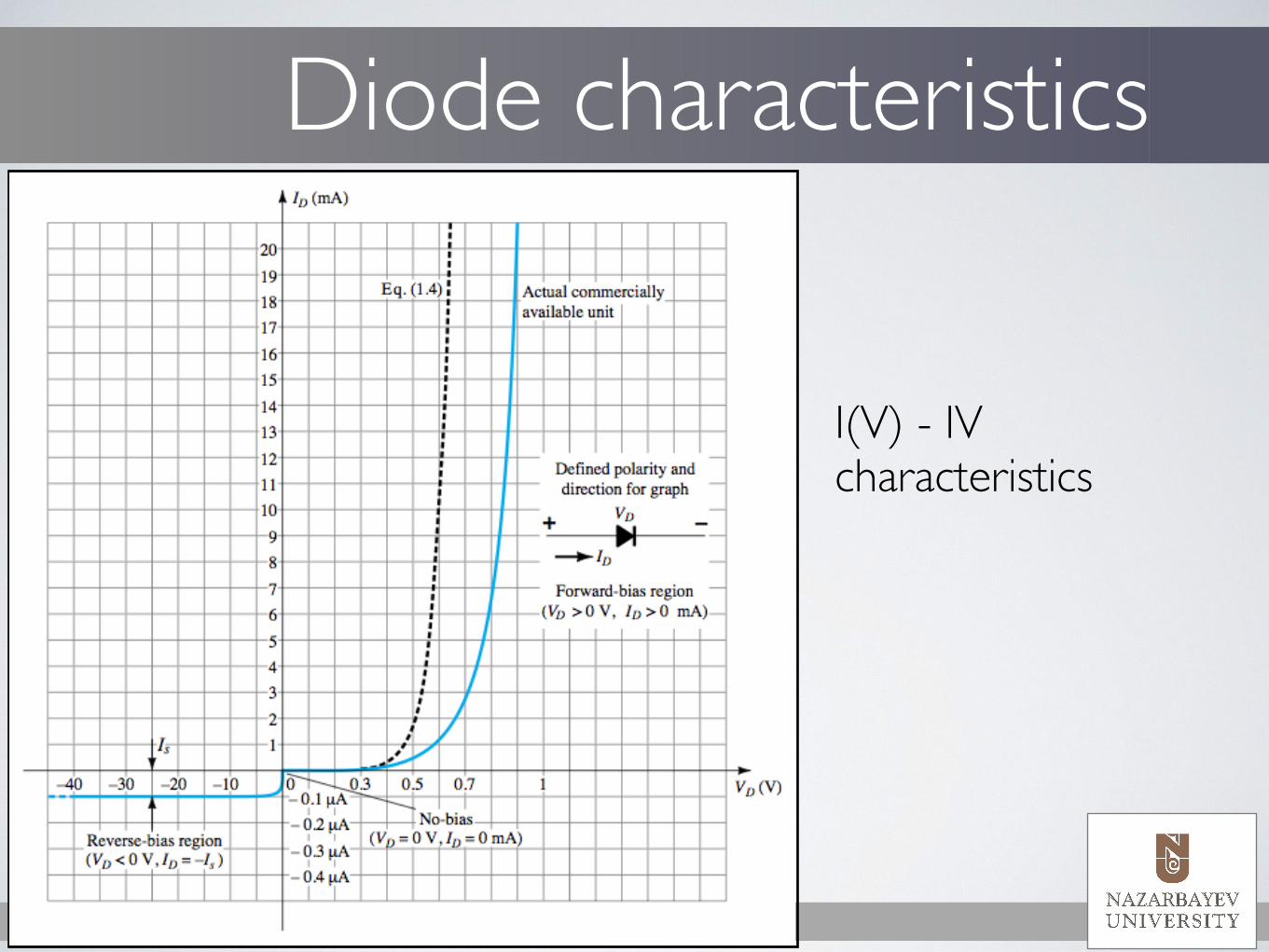
I(V) - IV characteristics

Analog Electronics - Diodes - Daniele Tosi
Diode characteristics
Active region High current for voltage > 0.7V
Analog Electronics - Diodes - Daniele Tosi
Diode characteristics
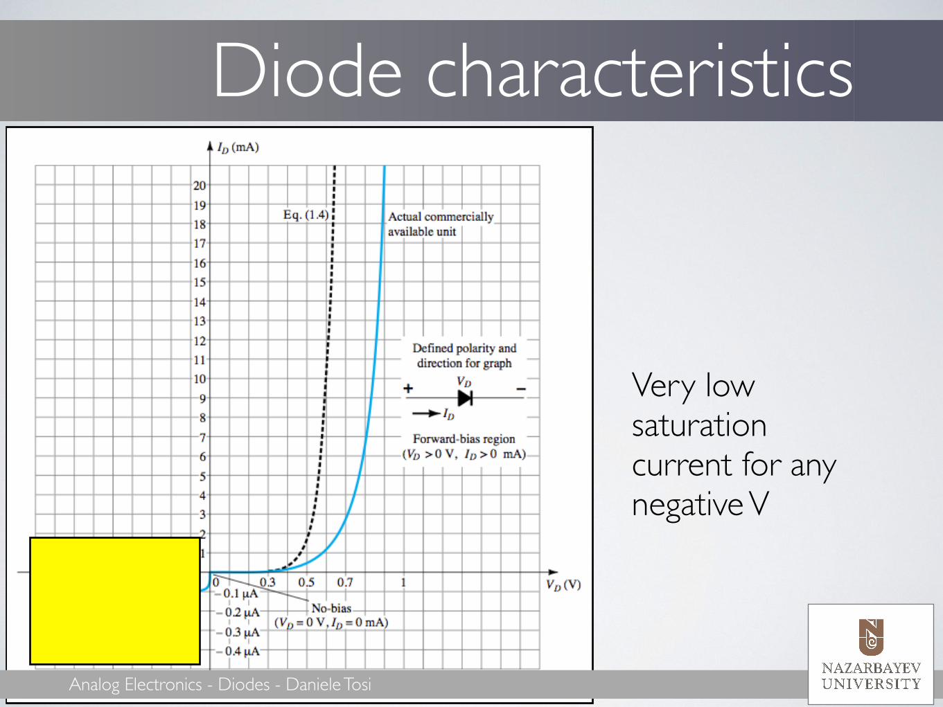
Very low saturation current for any negative V

Analog Electronics - Diodes - Daniele Tosi
“Knee” voltage
Knee: “discriminates” between reverse and forward mode !Knee voltage: 0.7 for Si diode
Analog Electronics - Diodes - Daniele Tosi
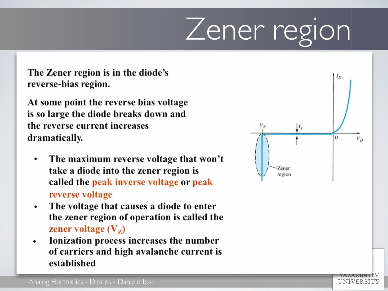
Zener region
Analog Electronics - Diodes - Daniele Tosi
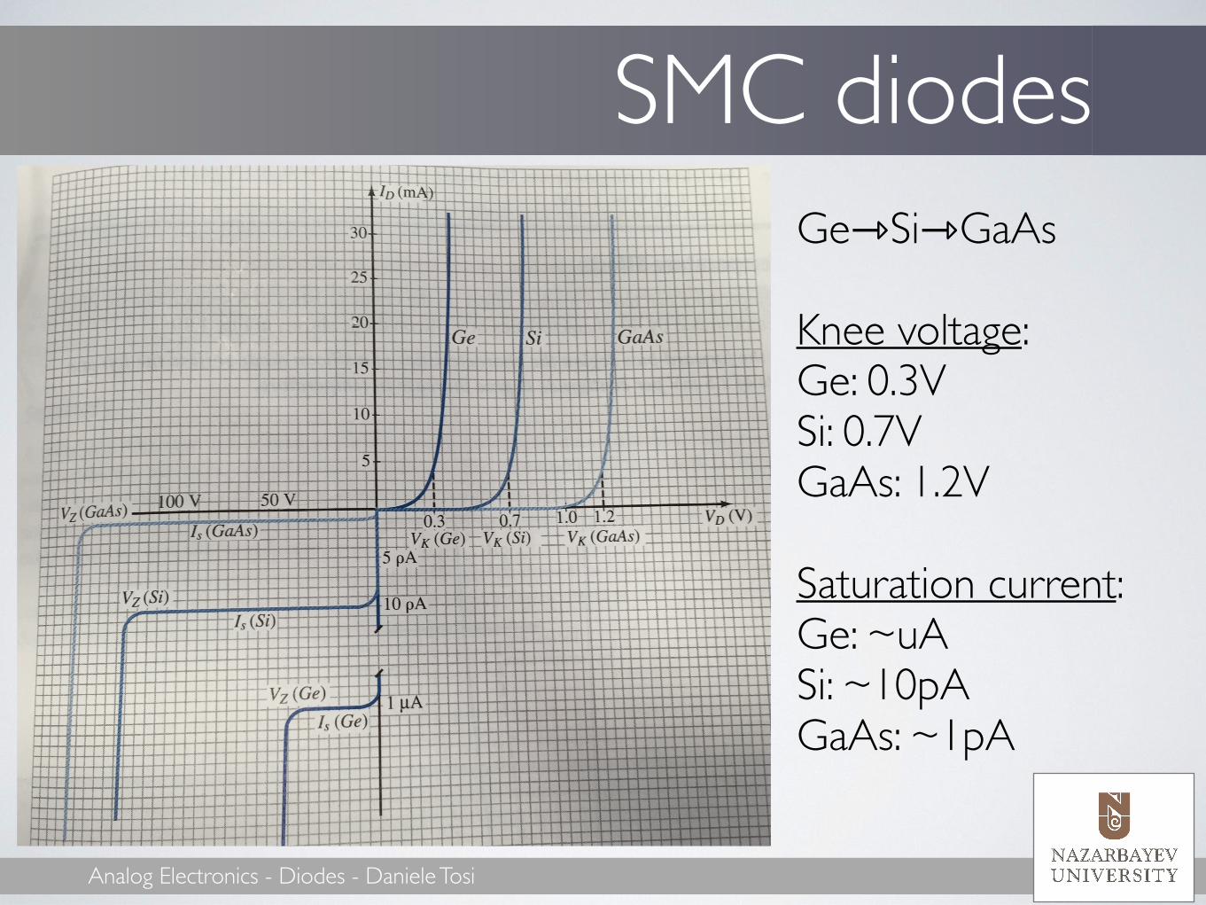
SMC diodesGe⇾Si⇾GaAs !Knee voltage: Ge: 0.3V Si: 0.7V GaAs: 1.2V !Saturation current: Ge: ~uA Si: ~10pA GaAs: ~1pA

Analog Electronics - Diodes - Daniele Tosi
Temperature sensitivityID = IS[exp(VD/nVT)-1] Temperature ⬆:
!Knee V ⬇ Sat. current ⬆ |Zener V| ⬆ !Stability with T: GaAs > Si > Ge

Analog Electronics - Diodes - Daniele Tosi
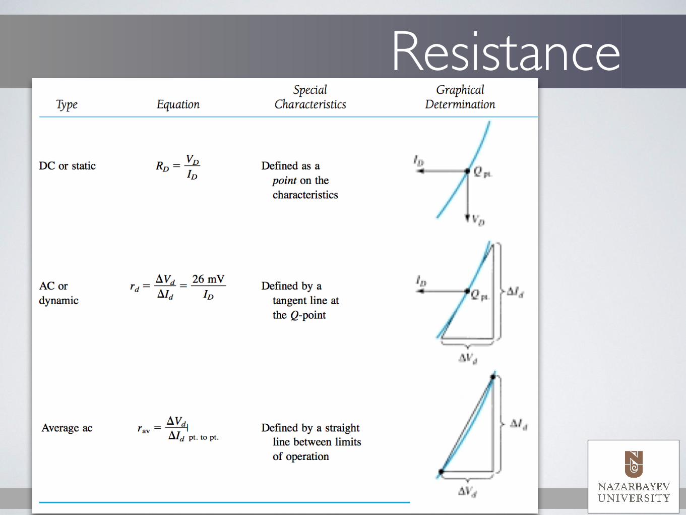
Diode resistanceDiode resistance: 1) DC or static 2) AC or dynamic 3) Average
Static resistance is calculated with Ohm’s law: RD =VD/ID
VD = -5V ⇨ RD = 5e11Ω VD = -0.9V ⇨ RD = 9e10Ω VD = 0V ⇨ RD = 8e8Ω VD = 0.7V ⇨ RD = 9e2Ω VD = 1.3V ⇨ RD = 3e-4Ω VD = 2.5V ⇨ RD = 2e-17Ω

Analog Electronics - Diodes - Daniele Tosi
AC resistanceSmall input in AC - small-signal analysis We can approximate the IV as a linear curve, at the point of operation (Q-point) !The AC resistance is obtained then as rd =ΔVd/ΔId
Important to understand the process for the calculus of the rd value in small-signal conditions!

Analog Electronics - Diodes - Daniele Tosi
AC resistanceID = IS exp
VDnVT −1
⎛
⎝⎜⎜
⎞
⎠⎟⎟
dIDdVD
= IS expVDnVT ⋅ 1
nVT= 1nVT
IS expVDnVT −1
⎛
⎝⎜⎜
⎞
⎠⎟⎟+ IS
⎡
⎣
⎢⎢
⎤
⎦
⎥⎥
dIDdVD
= 1nVT
ID + IS( )! IDnVT
Shockley:
Derivative:
ID
which can be rewritten as
in forward biasdVDdID
= rd =nVTID
≈ 26mVID
AC resistance: +rB

Analog Electronics - Diodes - Daniele Tosi
Average AC resistance
raverage =ΔVDΔID pt−pt
ΔId = 17mA - 2mA = 15 mA ΔVd = 0.725V - 0.65V = 75 mV rd = 75mV / 15mA = 5Ω
!
Analog Electronics - Diodes - Daniele Tosi
Resistance

Analog Electronics - Diodes - Daniele Tosi
Diode modelFor circuit analysis, diodes are replaced by a model, that simplifies the IV analysis.
Ideal diode Knee voltage Piecewise linear

Analog Electronics - Diodes - Daniele Tosi
Diode modelIdeal diode
Knee voltage
Piecewise linear
Analog Electronics - Diodes - Daniele Tosi
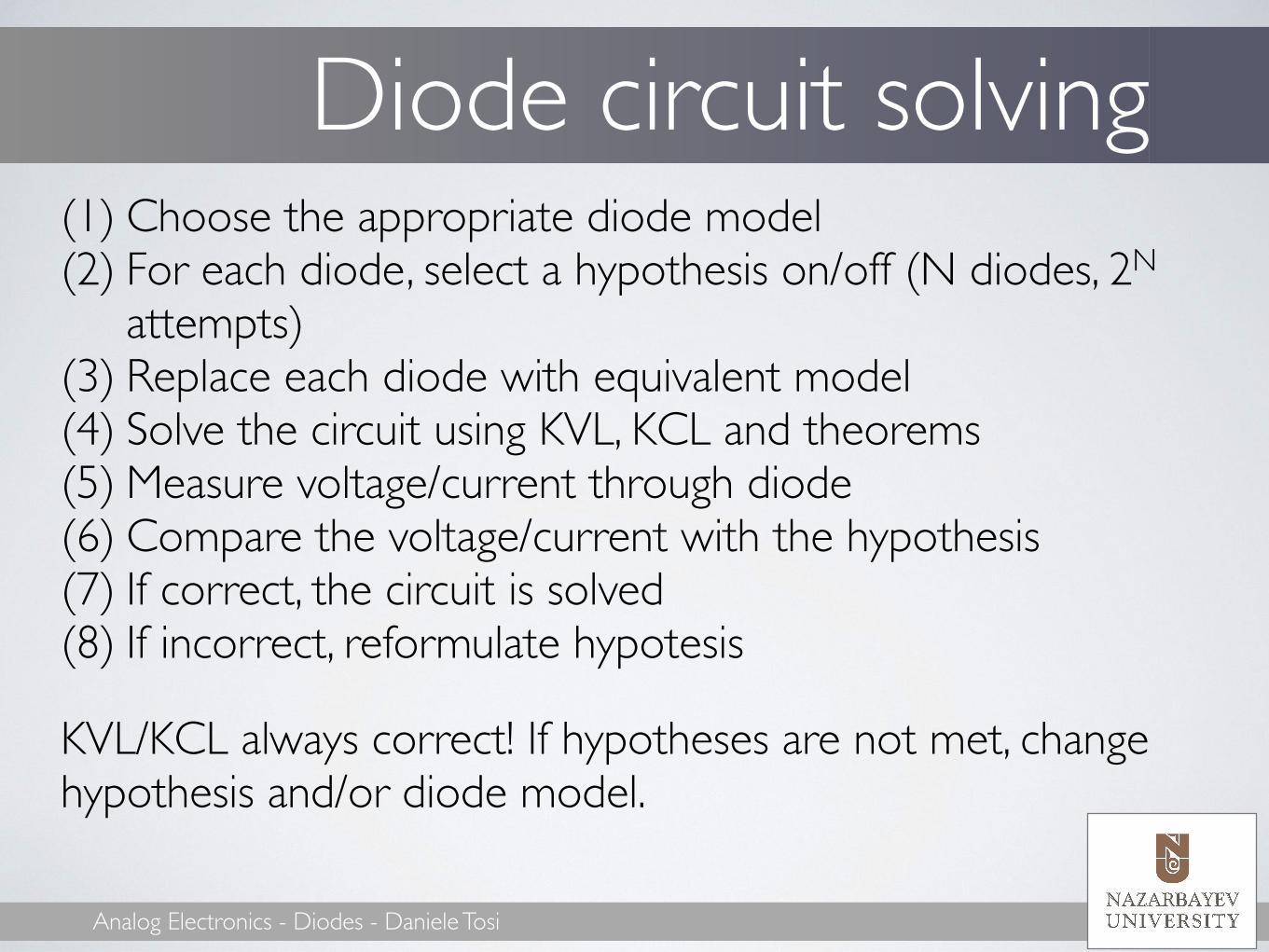
Diode circuit solving(1) Choose the appropriate diode model (2) For each diode, select a hypothesis on/off (N diodes, 2N
attempts) (3) Replace each diode with equivalent model (4) Solve the circuit using KVL, KCL and theorems (5) Measure voltage/current through diode (6) Compare the voltage/current with the hypothesis (7) If correct, the circuit is solved (8) If incorrect, reformulate hypotesis
KVL/KCL always correct! If hypotheses are not met, change hypothesis and/or diode model.
Analog Electronics - Diodes - Daniele Tosi
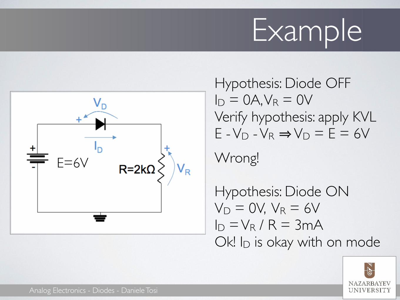
ExampleHypothesis: Diode OFF ID = 0A, VR = 0V Verify hypothesis: apply KVL E - VD - VR ⇒ VD = E = 6V Wrong! !Hypothesis: Diode ON VD = 0V, VR = 6V ID = VR / R = 3mA Ok! ID is okay with on mode
!
E=6V

Analog Electronics - Diodes - Daniele Tosi
Example (2)
Are both diodes on?

Analog Electronics - Diodes - Daniele Tosi
Example (AC)Si diode model !Diode ON - replace diode with 0.7V generator KVL: Vin - VD - VR = 0 ⇒ VR = Vin -0.7V When is diode on? ID = VR/R = (Vin - 0.7V)/R > 0A ⇒ Vin > 0.7V !Diode OFF - replace diode with open ID = 0A ⇒ VR = 0V When is diode off? KVL: Vin - VD = 0, VD = Vin ⇒ Vin < 0.7V !!

Analog Electronics - Diodes - Daniele Tosi
Diode capacitance
C = ε0εrAd
Closely related to the width of the depletion region
τ = RC CT = transition/depletion
CD = diffusion/storage

Analog Electronics - Diodes - Daniele Tosi
Reverse recovery time!tRR = reverse recovery time = Time required for a diode to stop conducting once it is switched from FW to REV bias.
!tRR, CD/T introduce frequency-dependent diode response

Analog Electronics - Diodes - Daniele Tosi
Commercial diodes
http://www.diodes.com/datasheets/ds12019.pdf
http://www.onsemi.com/pub_link/Collateral/BAS16XV2T1-D.PDF

Analog Electronics - Diodes - Daniele Tosi
Other diodesOptical applications: - LED (also base for lasers) - Photodiode (pin and avalanche) !
Voltage regulations: - Zener diode - Schottky diode (optoelectronics) - Tunnel diode (optoelectronics) - Varactor diode - Thermal, varactor, varicap, …

Analog Electronics - Diodes - Daniele Tosi
LED diodes
LED case
Symbol
!LED: light emitting diode. When in forward mode, photons are emitted Applications: light (UV/VIS), telecom (NIR), … FW bias voltage is 2-3V, resistance is quite ideal ➭ connect a diode in a circuit to check whether the correct V is applied

Analog Electronics - Diodes - Daniele Tosi
Photodiode!Photodiode: Converts light into current with a p-i-n structure Responsivity: measured in A/W (Amps output per W optical input) Si (UV/VIS), InGaAs (NIR) For very high speed (10-100Gb/s telecom!) Photodiodes are 0- or reverse-biased (-3.3 to -12V): on top of a saturation current, there is the “optical” current
Active areaC = ε0εrAd
Big A: easier focusing on detection surface, high capacitance (no high speed) Small A: smaller capacitance (high speed), difficult focusing !
Analog Electronics - Diodes - Daniele Tosi
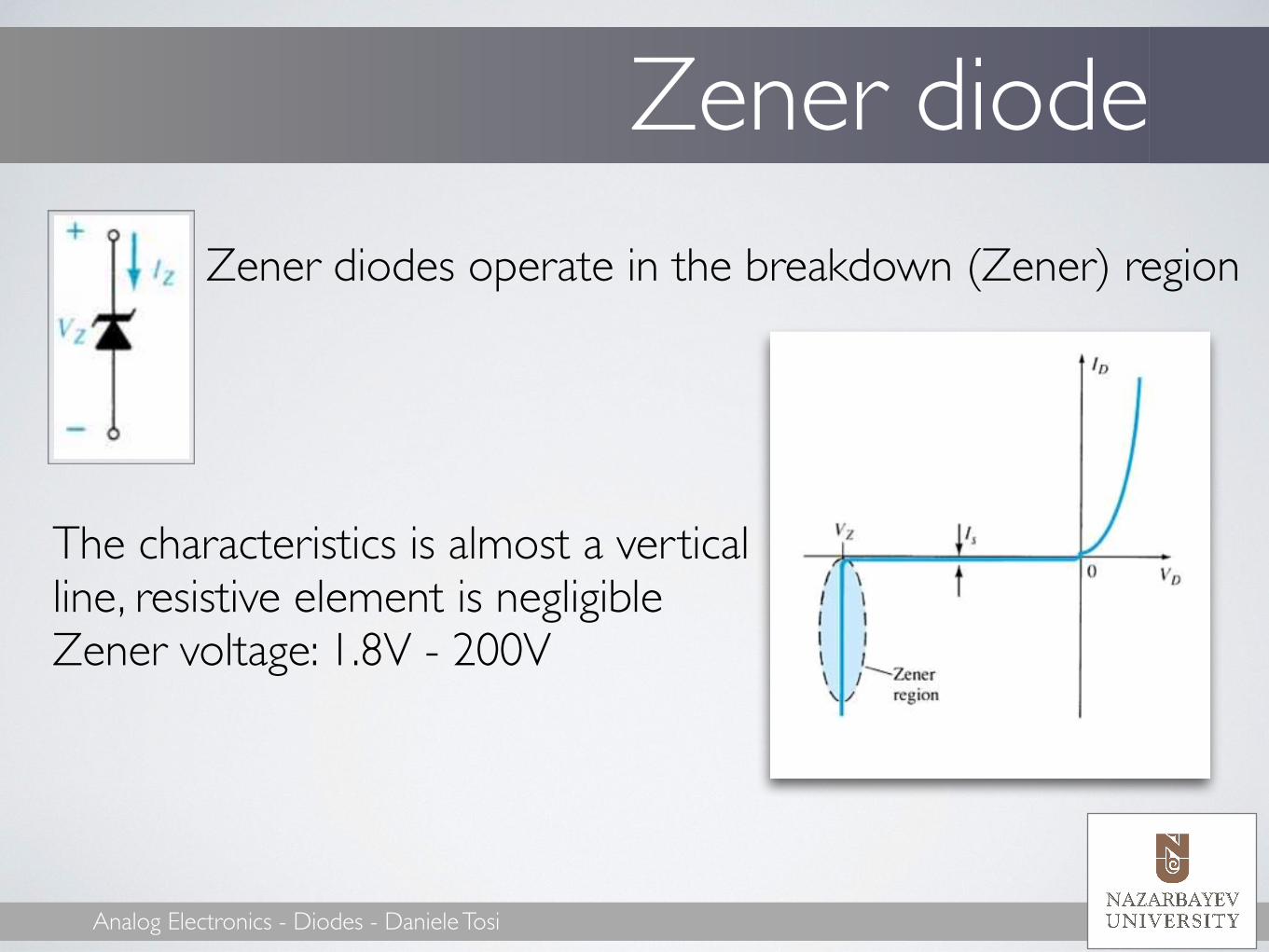
Zener diodeZener diodes operate in the breakdown (Zener) region
The characteristics is almost a vertical line, resistive element is negligible Zener voltage: 1.8V - 200V !


