12
Dual Adept Viper Robot Configuration Procedure Rev A, April, 2007
Dual Adept Viper RobotConfiguration Procedure
Rev A, April, 2007

The information contained herein is the property of Adept Technology, Inc., and shall not be repro-duced in whole or in part without prior written approval of Adept Technology, Inc. The informa-tion herein is subject to change without notice and should not be construed as a commitment by Adept Technology, Inc. This manual is periodically reviewed and revised.
Adept Technology, Inc., assumes no responsibility for any errors or omissions in this document. Critical evaluation of this manual by the user is welcomed. Your comments assist us in preparation of future documentation. Please email your comments to: [email protected].
Copyright © 2007 by Adept Technology, Inc. All rights reserved.
Adept, the Adept logo, the Adept Technology logo, AdeptVision, AIM, Blox, Bloxview, FireBlox, Fireview, HexSight, Meta Controls, MetaControls, Metawire, Soft Machines, and Visual Machines are registered trademarks of Adept Technology, Inc. Brain on Board is a registered trademark of
Adept Technology, Inc. in Germany.
ACE, ActiveV, Adept 1060 / 1060+, Adept 1850 / 1850 XP, Adept 540 Adept 560, Adept AnyFeeder, Adept Award, Adept C40, Adept C60, Adept CC, Adept Cobra 350, Adept Cobra 350 CR/ESD,
Adept Cobra 550, Adept 550 CleanRoom, Adept Cobra 600, Adept Cobra 800, Adept Cobra i600, Adept Cobra i800, Adept Cobra PLC server, Adept Cobra PLC800, Adept Cobra s600, Adept Cobra s800, Adept Cobra s800 Inverted, Adept Cobra Smart600, Adept Cobra Smart800, Adept DeskTop,
Adept FFE, Adept FlexFeeder 250, Adept IC, Adept iSight, Adept Impulse Feeder, Adept LineVision, Adept MB-10 ServoKit, Adept MC, Adept MotionBlox-10, Adept MotionBlox-40L,
Adept MotionBlox-40R, Adept MV Adept MV-10, Adept MV-19, Adept MV4, Adept MV-5, Adept MV-8, Adept OC, Adept Python, Adept sDIO, Adept SmartAmp, Adept SmartAxis, Adept
SmartController CS, Adept SmartController CX, Adept SmartModule, Adept SmartMotion, Adept SmartServo, Adept sMI6, Adept sSight, Adept Viper s650, Adept Viper s850, Adept Viper s1300,
Adept Viper s1700, AdeptCartesian, AdeptCast, AdeptForce, AdeptFTP, AdeptGEM, AdeptModules, AdeptMotion, AdeptMotion Servo, AdeptMotion VME, AdeptNet, AdeptNFS, AdeptOne, AdeptOne-MV, AdeptOne-XL, AdeptRAPID, AdeptSight, AdeptSix, AdeptSix 300,
AdeptSix 300 CL, AdeptSix 300 CR, AdeptSix 600, AdeptTCP/IP, AdeptThree, AdeptThree-MV, AdeptThree-XL, AdeptTwo, AdeptVision, AVI AdeptVision, AGS AdeptVision GV, AdeptVision
I, AdeptVision II, AdeptVision VME, AdeptVision VXL, AdeptVision XGS, AdeptVision XGS II, AdeptWindows,
AdeptWindows Controller, AdeptWindows DDE, AdeptWindows Offline Editor, AdeptWindows PC, AIM Command Server, AIM Dispense, AIM PCB, AIM VisionWare, A-Series, FlexFeedWare, HyperDrive, IO Blox, IO Blox, 88, MicroV+, MotionBlox, MotionWare, ObjectFinder, ObjectFinder
2000, PackOne, PalletWare, sAVI, S-Series, UltraOne, V, V+ and VisionTeach are trademarks of Adept Technology, Inc.
Any trademarks from other companies used in this publication are the property of those respective companies.
Printed in the United States of America

Adept Technology, Inc.
1.0 OverviewNOTE: If you purchased both robots at the same time as part of a Dual Robot system, then the two robots will be configured at the factory for the correct software setup. In this case you do not have to perform the steps in this document.
If you are setting up a system that was not configured at the factory, then you will need to go through this process. This procedure is valid for all robots in the Adept Viper product line.
The main steps in the configuration procedure are:
1. Confirm all robot equipment is installed and connected.
See Figure 1 on page 4 for reference and also read the Adept Viper s650/s850 Robot User’s Guide, the Adept Viper s1300 Robot User’s Guide, or the Adept Viper s1700 Robot User’s Guide for complete details.
2. Use the CONFIG_C utility to load the device-module files for each robot.
Select and load device module [42] for Adept Viper robot #1. Then repeat this process for robot #2. Save the data and reboot the system. See Section 3.0 on page 6 for details.
3. Use the DC_SETUP utility to configure each robot as a unique node on the SmartServo network.
In DC_SETUP, select option #2 => Configure Adept robot/axis gadgets. Follow the instructions on screen. For robot #1, identify the flashing LED on either the sDAI module in the PA-4 or on the MotionBlox-60R (MB-60R). Press Enter to configure. Return to the main menu, select option #6 => Change robot number. Then select option #2, and repeat this process for robot #2. See Section 4.0 on page 10 for details.
4. Use the DC_SETUP utility to assign the correct digital “logical” IO blocks to each robot.
Robot #1 uses block 1 and block 3; robot #2 uses block 2 and block 4. See Section 5.0 on page 12 for details.
Dual Adept Viper Robot Configuation Procedure, Rev A 3

Adept Technology, Inc.
2.0 Robot System InstallationThe diagrams below are provided for reference. See the Adept Viper s650/s850 Robot User’s Guide, the Adept Viper s1300 Robot User’s Guide, or the Adept Viper s1700 Robot User’s Guide for complete installation details.
Figure 1. Dual Viper s650/s850 with PA-4 System Cable Diagram
CN22
CN20
AIR1
AIR2
CN22
CN20
AIR1
AIR2
CAUTIONHIGH
VOLTAGEINSIDE
BRAKE STATUS
SmartServo
1
2
RS232
EXPIO
XSLV
CNPG123
CNPG456
CN25
CN29
DAIs
adept technology, inc.
LOW VOLTS ON
HV SAG/OVER TEMP FAULT
DO NOT REMOVE OR INSTALL THIS
SHORT FAULT
OPEN CKT FAULT
MODULE UNLESS HIGH VOLTS LEDIS COMPLETELY DISTINGUISHED
PWM ON
CH1
HIGH VOLTS ON
CH2
AMPLIFIER
CONTROL
CH2CH1
MOTOR
POWER
OUTPUT
J AMP J AMP J AMP
LOW VOLTS ON
HV SAG/OVER TEMP FAULT
DO NOT REMOVE OR INSTALL THIS
SHORT FAULT
OPEN CKT FAULT
MODULE UNLESS HIGH VOLTS LEDIS COMPLETELY DISTINGUISHED
PWM ON
CH1
HIGH VOLTS ON
CH2
AMPLIFIER
CONTROL
CH2CH1
MOTOR
POWER
OUTPUT
LOW VOLTS ON
HV SAG/OVER TEMP FAULT
DO NOT REMOVE OR INSTALL THIS
SHORT FAULT
OPEN CKT FAULT
MODULE UNLESS HIGH VOLTS LEDIS COMPLETELY DISTINGUISHED
PWM ON
CH1
HIGH VOLTS ON
CH2
AMPLIFIER
CONTROL
CH2CH1
MOTOR
POWER
OUTPUT
IEEE 1394 Cable #1
IEEE 1394 Cable #2
Adept PA-4 Power Chassis #1
AdeptSmartController CX
AdeptViper s650/s850Robot #1
To User-Supplied 24VDC Power Supply
To Front Panel
To T1 Pendant (optional)
XSYS Y cable
XSYS cable #1
XSYS cable #2
Ethernet to user-supplied PC
Terminator InstalledUser-Supplied
Ground Wire
User-Supplied Ground Wire
Grounding Terminal (M5)
Adept PA-4 Power Chassis #2
Arm Power/Signal Cable
AdeptViper s650/s850Robot #2
User-Supplied Ground Wire
Grounding Terminal (M5)
Arm Power/Signal Cable
R
ON
SmartServo IEEE-1394
1 2 3 4SF ES HDSW1 1.1 1.2 2.1 2.2OK
1 2 3
XDIO
LANHPE
OFF
XSYS
CAMERA
Eth 10/100
XUSR
Device Net
XFP
RS-232/TERM
RS-232-1
XMCP
BELT ENCODER
Sm
artC
ontr
olle
r C
X
-+ -+
RS-422/485
XDC1 XDC2
24V 5A
*S/N 3562-XXXXX*
RS-232-2
4 Dual Adept Viper Robot Configuation Procedure, Rev A
Adept Technology, Inc.
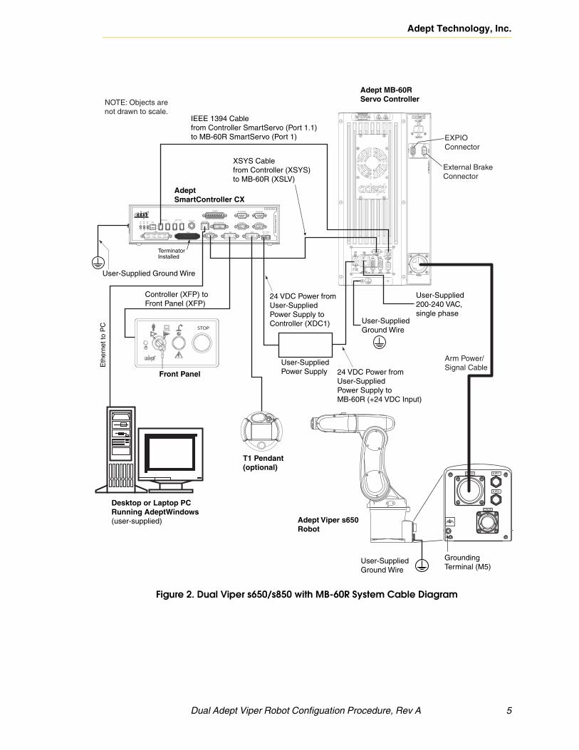
Figure 2. Dual Viper s650/s850 with MB-60R System Cable Diagram
CN22
CN20
AIR1
AIR2
Adept Viper s650Robot
User-SuppliedGround Wire
GroundingTerminal (M5)
Eth
erne
t to
PC
IEEE 1394 Cablefrom Controller SmartServo (Port 1.1)to MB-60R SmartServo (Port 1)
Adept MB-60RServo Controller
AdeptSmartController CX
User-SuppliedPower Supply
Controller (XFP) to Front Panel (XFP)
Front Panel
T1 Pendant (optional)
XSYS Cablefrom Controller (XSYS)to MB-60R (XSLV)
24 VDC Power fromUser-SuppliedPower Supply to Controller (XDC1)
Desktop or Laptop PCRunning AdeptWindows (user-supplied)
Terminator Installed
User-Supplied Ground Wire
External Brake Connector
Arm Power/Signal Cable
24 VDC Power fromUser-SuppliedPower Supply to MB-60R (+24 VDC Input)
User-Supplied200-240 VAC, single phase
EXPIOConnector
NOTE: Objects arenot drawn to scale.
User-SuppliedGround WireSTOP
R
R
ON
SmartServo IEEE-1394
1 2 3 4SF ES HDSW1 1.1 1.2 2.1 2.2OK
1 2 3
XDIO
LANHPE
OFF
XSYS
CAMERA
Eth 10/100
XUSR
Device Net
XFP
RS-232/TERM
RS-232-1
XMCP
BELT ENCODER
Sm
artC
ontr
olle
r C
X
-+ -+
RS-422/485
XDC1 XDC2
24V 5A
*S/N 3562-XXXXX*
RS-232-2
Dual Adept Viper Robot Configuation Procedure, Rev A 5

Adept Technology, Inc.
3.0 Loading Device Modules with CONFIG_CUse the CONFIG_C utility to load the device-module files for each robot.
1. Turn on power to each PA-4 or MB-60R, and then to the SmartController.
2. Start AdeptWindows and a screen similar to Figure 3 will appear.
Figure 3. Typical Startup Screen
3. Load the CONFIG_C utility by typing the following command at the V+ dot prompt:
load \util\config_c
4. Execute the CONFIG_C utility by typing the following command at the V+ dot prompt:
exe 1 a.config_c
The following screen is displayed.
6 Dual Adept Viper Robot Configuation Procedure, Rev A
Adept Technology, Inc.
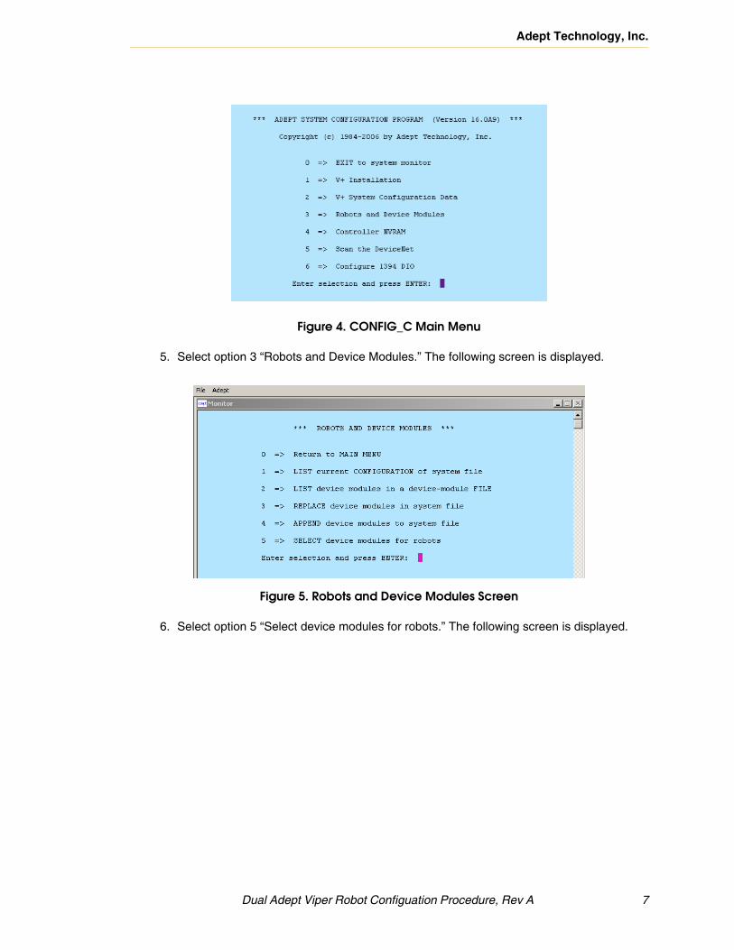
Figure 4. CONFIG_C Main Menu
5. Select option 3 “Robots and Device Modules.” The following screen is displayed.
Figure 5. Robots and Device Modules Screen
6. Select option 5 “Select device modules for robots.” The following screen is displayed.
Dual Adept Viper Robot Configuation Procedure, Rev A 7

Adept Technology, Inc.
Figure 6. Device Module Selection
7. At the prompt, “Do you want to change this selection?,” enter Y. The following screen is displayed.
Figure 7. Device Module Selection
8. At the prompt, “Enter selection number,” enter 42, then Y to confirm. The following screen is displayed.
8 Dual Adept Viper Robot Configuation Procedure, Rev A
Adept Technology, Inc.
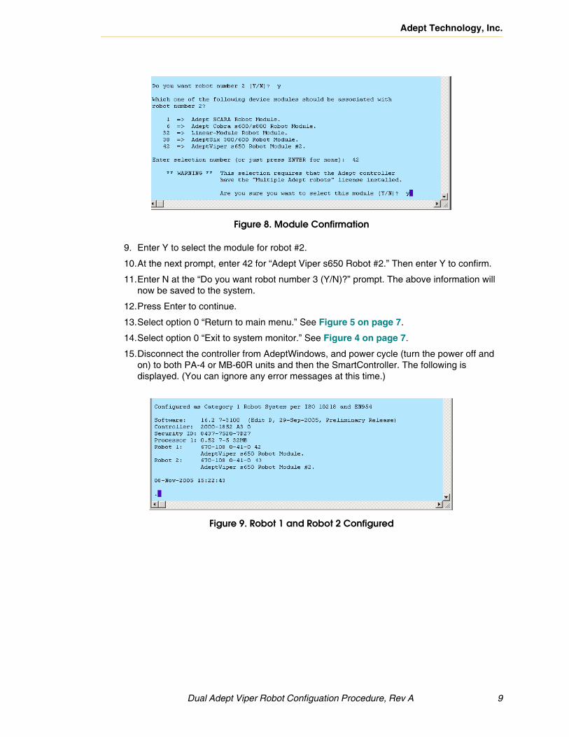
Figure 8. Module Confirmation
9. Enter Y to select the module for robot #2.
10.At the next prompt, enter 42 for “Adept Viper s650 Robot #2.” Then enter Y to confirm.
11.Enter N at the “Do you want robot number 3 (Y/N)?” prompt. The above information will now be saved to the system.
12.Press Enter to continue.
13.Select option 0 “Return to main menu.” See Figure 5 on page 7.
14.Select option 0 “Exit to system monitor.” See Figure 4 on page 7.
15.Disconnect the controller from AdeptWindows, and power cycle (turn the power off and on) to both PA-4 or MB-60R units and then the SmartController. The following is displayed. (You can ignore any error messages at this time.)
Figure 9. Robot 1 and Robot 2 Configured
Dual Adept Viper Robot Configuation Procedure, Rev A 9

Adept Technology, Inc.
4.0 Configuring SmartServo Nodes with DC_SETUPUse the DC_SETUP utility to configure each robot as a unique node on the SmartServo network.
1. Load the DC_SETUP utility by typing the following command at the V+ dot prompt:
load \util\dc_setup
2. Execute the DC_SETUP utility by typing the following command at the V+ dot prompt:
exe 1 a.dc_setup
The main DC_SETUP menu appears, as shown in Figure 10.
Figure 10. DC_SETUP Main Menu
3. In DC_SETUP, select option 2 “Configure Adept robot/axis gadgets.” Follow the instructions on screen.
NOTE: If the robots were shipped from the factory configured as single robot systems, both robots will be configured as robot 1. At this stage, you must press the space bar to cycle through each robot to “unconfigure” them as robot #1 before you continue. If you do not visit each servo node, there will be no servo nodes presented to you later in the procedure when you configure robot #2.
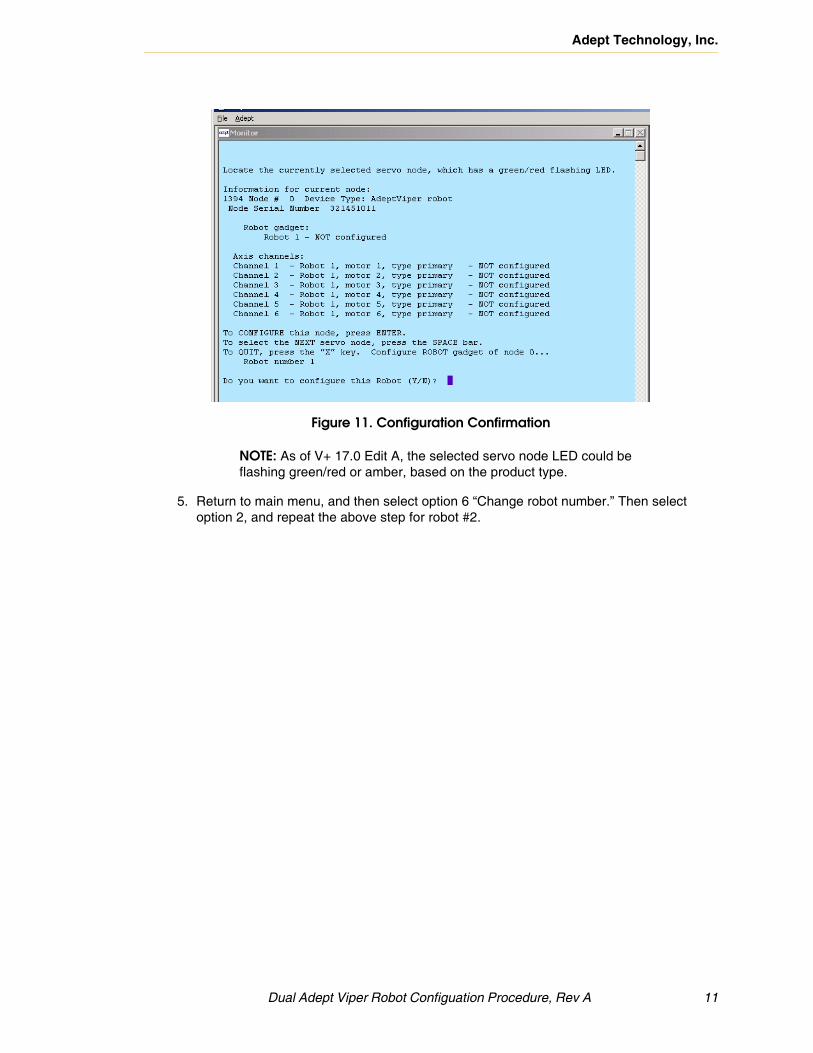
4. After several screens, you will see a screen similar to Figure 11. For robot #1, identify the flashing LED on the sDAI module in the PA-4 or MB-60R #1. Press Enter to configure robot #1.
10 Dual Adept Viper Robot Configuation Procedure, Rev A
Adept Technology, Inc.
Figure 11. Configuration Confirmation
NOTE: As of V+ 17.0 Edit A, the selected servo node LED could be flashing green/red or amber, based on the product type.
5. Return to main menu, and then select option 6 “Change robot number.” Then select option 2, and repeat the above step for robot #2.
Dual Adept Viper Robot Configuation Procedure, Rev A 11
Adept Technology, Inc.
5.0 Configuring Digital I/O Blocks with DC_SETUPUse the DC_SETUP utility to assign the correct digital “logical” IO blocks to each robot.
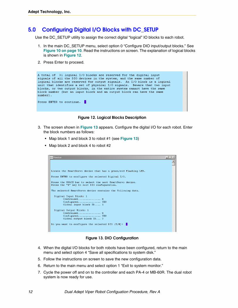
1. In the main DC_SETUP menu, select option 0 “Configure DIO input/output blocks.” See Figure 10 on page 10. Read the instructions on screen. The explanation of logical blocks is shown in Figure 12.
2. Press Enter to proceed.
Figure 12. Logical Blocks Description
3. The screen shown in Figure 13 appears. Configure the digital I/O for each robot. Enter the block numbers as follows:
• Map block 1 and block 3 to robot #1 (see Figure 13)
• Map block 2 and block 4 to robot #2
Figure 13. DIO Configuration
4. When the digital I/O blocks for both robots have been configured, return to the main menu and select option 4 “Save all specifications to system disk.”
5. Follow the instructions on screen to save the new configuration data.
6. Return to the main menu and select option 1 “Exit to system monitor.”
7. Cycle the power off and on to the controller and each PA-4 or MB-60R. The dual robot system is now ready for use.
12 Dual Adept Viper Robot Configuation Procedure, Rev A


