INSTRUCTION MANUAL i2820H DUAL BAND FM TRANSCEIVER This device complies with Part 15 of the FCC rules. Operation is sub- ject to the following two conditions: (1) This device may not cause harmful interference, and (2) this device must accept any interference received, including interference that may cause undesired operation.
Transcript
INSTRUCTION MANUAL
i2820HDUAL BAND FM TRANSCEIVER
This device complies with Part 15 of the FCC rules. Operation is sub-ject to the following two conditions: (1) This device may not causeharmful interference, and (2) this device must accept any interferencereceived, including interference that may cause undesired operation.
i
FOREWORDThank you for purchasing this Icom product. The IC-2820HVHF/UHF FM TRANSCEIVER is designed and built with Icom’s su-perior technology and craftsmanship. With proper care, thisproduct should provide you with years of trouble-free opera-tion.
We want to take a couple of moments of your time to thankyou for making your IC-2820H your radio of choice, and hopeyou agree with Icom’s philosophy of “technology first.” Manyhours of research and development went into the design ofyour IC-2820H.
DD FEATURES
Diversity reception is ready
DV (Digital Voice) with GPS operation capabilities (Optional UT-123 is required)
V/V, U/U simultaneous receive capability
Independent controls for each left and rightbands
Separate controller for flexible installation
Remote control microphone standard
IMPORTANTREAD ALL INSTRUCTIONS carefully and completelybefore using the transceiver.
SAVE THIS INSTRUCTION MANUAL— This in-struction manual contains important operating instructions forthe IC-2820H.
EXPLICIT DEFINITIONS
WORD DEFINITION
R WARNING!
CAUTION
NOTE
Personal injury, fire hazard or electric shockmay occur.
Equipment damage may occur.
Recommended for optimum use. No risk ofpersonal injury, fire or electric shock.
Icom, Icom Inc. and the logo are registered trademarks of IcomIncorporated (Japan) in the United States, the United Kingdom, Ger-many, France, Spain, Russia and/or other countries.
RWARNING RF EXPOSURE! This device emits RadioFrequency (RF) energy. Extreme caution should be observed whenoperating this device. If you have any questions regarding RF expo-sure and safety standards please refer to the Federal Communica-tions Commission Office of Engineering and Technology’s report onEvaluating Compliance with FCC Guidelines for Human Radio fre-quency Electromagnetic Fields (OET Bulletin 65).
RWARNING! NEVER connect the transceiver to an AC out-let. This may pose a fire hazard or result in an electric shock.
RWARNING! NEVER operate the transceiver while driving avehicle. Safe driving requires your full attention—anything less mayresult in an accident.
NEVER connect the transceiver to a power source of more than16 V DC. This will damage the transceiver.
NEVER connect the transceiver to a power source using reversepolarity. This will damage the transceiver.
NEVER cut the DC power cable between the DC plug and fuseholder. If an incorrect connection is made after cutting, the transceivermay be damaged.
NEVER expose the transceiver to rain, snow or any liquids. Thetransceiver may be damaged.
NEVER operate or touch the transceiver with wet hands. This mayresult in an electric shock or damage the transceiver.
NEVER place the transceiver where normal operation of the vehi-cle may be hindered or where it could cause bodily injury.
NEVER let objects impede the operation of the cooling fan on therear panel.
DO NOT push the PTT when not actually desiring to transmit.
DO NOT allow children to play with any radio equipment contain-ing a transmitter.
During mobile operation, DO NOT operate the transceiver with-out running the vehicle’s engine. When the transceiver’s power is ONand your vehicle’s engine is OFF, the vehicle’s battery will soon be-come exhausted.
AVOID using or placing the transceiver in direct sunlight or inareas with temperatures below –10°C or above +60°C.
BE CAREFUL! The transceiver will become hot when operat-ing it continuously for long periods.
AVOID setting the transceiver in a place without adequate venti-lation. Heat dissipation may be affected, and the transceiver may bedamaged.
AVOID the use of chemical agents such as benzine or alcoholwhen cleaning, as they can damage the transceiver’s surfaces.
USE Icom microphones only (supplied or optional). Other manu-facturer’s microphones have different pin assignments and may dam-age the transceiver if attached.
For U.S.A. onlyCAUTION: Changes or modifications to this device, not ex-pressly approved by Icom Inc., could void your authority tooperate this device under FCC regulations.
ii
PRECAUTIONS
iii
TABLE OF CONTENTSSUPPLIED ACCESSORIES
qDC power cable (3 m) ………………………………………1wController cable (10 cm†; 3.9 in†) …………………………1eSeparation cable (3.4 m†; 11.2 ft†) …………………………1rMicrophone (HM-133)* ……………………………………1tFuse (20 A) …………………………………………………1yMicrophone hanger …………………………………………1uMounting screws, nuts and washers …………………1 setiMobile mounting bracket …………………………………1oMicrophone connector plate with screw ……………1 set!0Remote controller bracket …………………………………1*HM-154 HAND MICROPHONE may be supplied with some versions.†Approx.
Installation ....................................................................................... I Your first contact ......................................................................... VIII Repeater operation ........................................................................ X Programming memory channels.................................................... XI
1 PANEL DESCRIPTION ............................................................... 1–10 Front panel— controller ................................................................. 1 Function display ............................................................................. 3 Main unit ........................................................................................ 5 Microphone (HM-133) .................................................................... 7 Microphone keypad ........................................................................ 8 Optional microphones (HM-118N/TN/TAN)................................... 10
2 SETTING A FREQUENCY ........................................................ 11–15 Preparation ................................................................................... 11 Using the tuning dial .................................................................... 13 Using the [Y]/[Z] keys ................................................................. 13 Using the keypad ......................................................................... 13 Tuning step selection ................................................................... 14 Lock functions .............................................................................. 15
3 BASIC OPERATION ................................................................. 16–21 Receiving ..................................................................................... 16 Monitor function ........................................................................... 16 Squelch attenuator ....................................................................... 17 V/V, U/U simultaneous receive (Para-watch) ............................... 18 Sub band mute/sub band busy beep ........................................... 19 Transmitting ................................................................................. 20
12345678910111213141516171819
iv
Selecting output power ................................................................ 20 One-touch PTT function ............................................................... 21 Audio mute function ..................................................................... 21
4 REPEATER OPERATION ......................................................... 22–28 General ........................................................................................ 22 Accessing a repeater ................................................................... 23 Subaudible tones ......................................................................... 25 Offset frequency .......................................................................... 27 Auto repeater (USA version only) ................................................ 28
5 MEMORY OPERATION ............................................................ 29–37 General description ...................................................................... 29 Memory channel selection ........................................................... 29 Programming a memory channel ................................................. 30 Transferring memory contents ..................................................... 32 Memory clearing .......................................................................... 34 Memory bank selection ................................................................ 35 Memory bank setting .................................................................... 36 Transferring bank contents .......................................................... 37
InstallationD Precaution— magnetsRCAUTIONMagnets are used for the controller’s attachment to the mainunit.
NEVER hold the whole unit by the controller only when carry-ing the transceiver. Carry the transceiver holding the mainunit. If held by the controller, the main unit may drop off andmay result in injury to the person carrying it or damage thetransceiver.
NEVER attach the controller on the main unit’s top cover, par-ticularlly around the internal speaker grill. It may cause thecontents of the CPU and memory device could be deleted.
NEVER put the controller near a clock, television set (CRTtype), magnetic compass and any magnetic/IC cards, creditcards, etc. It may cause the product to malfunction, and thecontent of the magnetic card could be deleted.
Please note that the controller may drop off when a high im-pact or vibration is applied.
D Installation methods• Single body installation
• The supplied mounting bracket can be used for the mainunit installation.
Transceiver
II
QUICK REFERENCE GUIDE
• Remote installation
• The supplied remote controller bracket and separation cablecan be used for installation.
• Optional OPC-1156 SEPARATION CABLE (3.5 m; 11.5 ft) isavailable for extend the separation cable.
• Optional OPC-440 MICROPHONE CABLE (5.0 m; 16.4 ft) andOPC-647 (2.5 m; 8.2 ft) are available to extend the micro-phone cable.
• Optional OPC-441 SPEAKER CABLE (5.0 m; 16.4 ft) is avail-able to extend the speaker cable.
D LocationSelect a location which can support the weight of the trans-ceiver and does not interfere with driving. We recommend thelocations shown in the diagram below.
NEVER place the transceiver or remote controller where nor-mal operation of the vehicle may be hindered or where itcould cause bodily injury.
NEVER place the transceiver or remote controller where airbag deployment may be obstructed.
DO NOT place the transceiver or remote controller where hotor cold air blows directly onto it.
AVOID placing the transceiver or remote controller in directsunlight.
@@ÀÀQQ¢¢@ÀQ¢@ÀQ¢@ÀQ¢Controller
Main unit
Main unit
Main unit
Main body
Front panel
Qu
ick
refe
ren
ce g
uid
e
III
QUICK REFERENCE GUIDE
D Using the mounting bracketqDrill 4 holes where the mounting bracket is to be installed.
• Approx. 5.5–6 mm (1⁄4″) when using nuts; approx. 2–3 mm (1⁄8″)when using self-tapping screws.
w Insert the supplied screws, nuts and washers through themounting bracket and tighten.
eAdjust the angle for your suitable position.
D Controller/Separation cable connectionTwo connection cables, conteoller cable (10 cm; 3.9 in) for sin-gle body installation and separation cable (3.4 m; 11.2 ft) for re-mote installation, are supplied with the IC-2820H.
Connect the controller and the main unit using with the sup-plied connection cable as follows.
IMPORTANT!— number of pinNumber of pin, between both side connectors of the connec-tion cable are different— one side is 6-pin, other side is 4-pin.You should connect the 6-pin connector to the main unit, andthe 4-pin connector to the controller.
Controller
Main unit
6-pin connector 4-pin connector
NutSpring washer
When usingself-tappingscrews
Flat washerMounting nut
Mountingbracket
25˚
IV
QUICK REFERENCE GUIDE
D Microphone connectionA microphone connector is available on the main unit frontpanel. Connect the supplied microphone connector as illus-trated below.
Attach the supplied microphone connector plate after the mi-crophone connection, otherwise the controller will easilydropped off when the microphone cable is pulled during sin-gle body installation.
D Controller’s attachmentYou can attach the controller of the IC-2820H in one of 2methods.
• Example 1
• Example 2
Controller Microphone
Main unit
Qu
ick
refe
ren
ce g
uid
e
V
D Remote installationThe supplied remote controller bracket is used for remote in-stallation.
• Attach the remote controllerbracket onto a flat surfaceusing with 4 self-tappingscrews (2.6 mm(d)), or double-sticky tape, etc., as at left,then attach remote controllerto the bracket
Hint!The supplied remote controller bracket may fits to a mount-ing angle, such as for car TV set as below. Ask your car ac-cessory shop, if desired.
D Battery connection RWARNING NEVER remove the fuse holders from the
DC power cable. NEVER connect the transceiver directly to a 24 V battery. DO NOT use the cigarette lighter socket for power con-
nections. (See p. ?? for details)Attach a rubber grommet when passing the DC power cablethrough a metal plate to prevent a short circuit.
• CONNECTING TO A DC POWER SOURCE
IC-2820H
Fuses20 A
blackred⊕ −
12 V
Grommet
NOTE: Use terminals for the cable connections.
WARNING!NEVERremove thefuse holders.
Crimp Solder
12 Vbattery
SuppliedDC power cable
+ red_ black
Remote controller bracket
QUICK REFERENCE GUIDE
VI
QUICK REFERENCE GUIDE
D DC power supply connectionUse a 13.8 V DC power supply with at least 15 A capacity.
Make sure the ground terminal of the DC power supply isgrounded.
• CONNECTING TO A DC POWER SUPPLY
See p. ?? for fuse replacement.
DC powersupply 13.8 V
to anACoutlet
Fuses20 Ablack
red⊕−
⊕−
IC-2820H
Qu
ick
refe
ren
ce g
uid
e
VII
QUICK REFERENCE GUIDE
D Antenna installation• Antenna locationTo obtain maximum performance from the transceiver, selecta high-quality antenna and mount it in a good location. It isnot necessary to use radials on a magnetic mount (“magmount”) antenna.
• Antenna connectorThe antenna uses a PL-259 connector.
• PL-259 CONNECTOR
q Slide the coupling ringdown. Strip the cablejacket and soft solder.
w Strip the cable as shownat left. Soft solder the cen-ter conductor.
e Slide the connector bodyon and solder it.
r Screw the coupling ringonto the connector body.
(10 mm ≈ 3⁄8 in)
NOTE: There are many publications covering proper an-tennas and their installation. Check with your local dealerfor more information and recommendations.
30 mm
10 mm (soft solder)
10 mm
1–2 mm
solder solder
Softsolder
Coupling ring
To antennafor diversity
To antennafor Tx/Rx
Roof-mount antenna(Drill a hole or use a magnetic mount.)
Gutter-mount antenna
Trunk-mountantenna
VIII
QUICK REFERENCE GUIDE
Your first contactNow that you have your IC-2820H installed in your car orshack, you are probably excited to get on the air. We wouldlike to take you through a few basic operation steps to makeyour first “On The Air” an enjoyable experience.
1. Turning ON the transceiverBefore powering up your IC-2820H, you may want to makesure the audio volume and squelch level controls are set in9–10 o’clock positions.
Although you have purchased a brand new transceiver, somesettings may be changed from the factory defaults becauseof the QC process. Resetting the CPU is necessary to startfrom factory default.
While pushing both band’s [M/CALL•MW], push and hold[PWR] for 1 sec. to reset the CPU.
2. Selecting the main bandThe IC-2820H displays 2 frequencies on left and right bandssimultaneously. However, transmission, some keys and mi-crophone’s operation are accepted for the main band only.
Push the desired band’s (left or right) [MAIN•BAND] to se-lect the main band.• “Q” appears for the main band.
Using the HM-133You can select the main band from the HM-133.
Push
Push again
[MAIN•BAND]
[M/CALL•MW]
While pushing both [M/CALL•MW], turn power ON.
[M/CALL•MW]
[PWR]
Set both [VOL] and [SQL] controls to 9–10 o’clock positions.
Qu
ick
refe
ren
ce g
uid
e
IX
QUICK REFERENCE GUIDE
3. Selecting the operating frequency bandThe IC-2820H has 2 m and 70 cm bands for each left andright band. The operating band can be exchanged betweenthem, and the same bands, V/V and U/U settings are alsopossible.
Push and hold the desired band’s (left or right)[MAIN•BAND] for 1 sec. then rotate the appropriate band’s[DIAL].• Push the [MAIN•BAND] momentarily to return to frequency in-
dication.
4. Tune the frequencyThe tuning dial will allow you to dial in the frequency you wantto operate. Pages ?? and ?? will instruct you on how to setthe tuning speed.
Using the HM-133You can directly enter the frequency with the HM-133 keypadfor the main band.
[EXAMPLE]: Setting frequency to 145.3625 MHz.
Push
Push
Push
Push
Rotate the desired [DIAL].[DIAL]
[MAIN•BAND]
Frequency band initial is displayed.
X
QUICK REFERENCE GUIDE
Repeater operation1. Setting duplex Push desired band’s [MAIN•BAND] to select the main band.Push [DUP•MONI] once or twice to select minus duplex orplus duplex.• The USA version has an auto repeater function, therefore, setting
duplex is not required.
2. Repeater tone Push [TONE•DTMF] several times until “TONE” appears, ifthe repeater requires a subaudible tone to be accessed.
Using the HM-133Plus or minus duplex selection and the repeater tone settingcan be made easily via HM-133.Push [DUP– 7(TONE)] for minus duplex; [DUP+ 8(TSQLS)]for plus duplex selection, push [FUNC] then [DUP– 7(TONE)]to turn the repeater tone ON.
Push
Push , then
Push
Push [TONE•DTMF].
Push [DUP•MONI].
Qu
ick
refe
ren
ce g
uid
e
XI
QUICK REFERENCE GUIDE
Programming memory channelsThe IC-2820H has a total of 522 memory channels (including20 scan edges and 2 call channels) for storing often used operat-ing frequency, repeater settings, etc. Any memory channel can be recalled from either left or rightband.
1. Setting a frequencyIn VFO mode, set the desired operating frequency with re-peater, tone and tuning steps, etc. Push the desired band’s [V/MHz•SCAN] to select VFO. Rotate the same band’s [DIAL] to set the desired fre-
quency.• Set other data, such as repeater tone, duplex information, tuning
step), if desired.
2. Selecting a memory channel Push and hold the same band’s [M/CALL•MW] for 1 sec.,then rotate the same band’s [DIAL] to select the desiredmemory channel.• “X” indicator and memory channel number blink.
3. Writing a memory channelPush and hold the same band’s [M/CALL•MW] for 1 sec. toprogram.• 3 beeps sound• Return to VFO mode automatically after the program.• Memory channel number automatically increases when continuing
to push the [M/CALL•MW] after programming.
Push [M/CALL•MW] for 1 sec.
XII
QUICK REFERENCE GUIDE
Using the HM-133qPush [MR/CALL] to select memory mode.wPush [ENT C(T-OFF)] first, then enter the desired memory
channel via the keypad.ePush [VFO/LOCK] to select VFO mode, then set the de-
sired operating frequency, including offset direction, tonesettings, etc. Push [VFO/LOCK] to select VFO. Push [ENT C(T-OFF)] first, then enter the desired oper-
ating frequency via the keypad.• Set other data, such as repeater tone, duplex information, tun-
ing step, if necessary.rPush [FUNC] then push and hold [CLR A(MW)] for 1 sec.
to program.
• 3 beeps sound• Memory channel number automatically increases when continu-
ing to push [CLR A(MW)] after programming.
Push ,
then
Qu
ick
refe
ren
ce g
uid
e
Front panel— controller
qPOWER KEY [PWR]Push and hold for 1 sec. to turn power ON and OFF.
wFUNCTION•LOCK KEY [FF• ] Push to display the function guide. (p. ??) Push and hold for 1 sec. to turn the lock function ON
and OFF. (p. ??)
eOUTPUT POWER•PRIORITY KEY [LOW•PRIO] Each push changes the output power selection. (p. ??) Push and hold for 1 sec. to start a priority watch. (p. ??)
rTONE•DTMF KEY [TONE•DTMF] Each push selects a tone function. (pgs. ??, ??)
• TONE, TSQL , TSQL, TSQL-R, DTCS , DTCS, DTCS-R,DSQL , DSQL, CSQL , CSQL or tone function OFF canbe selected.
Push and hold for 1 sec. to enter DTMF set mode.(p. ??)
tDUPLEX•MONITOR KEY [DUP•MONI] Push to select DUP–, DUP+ and simplex (no indications)
operation. (p. ??) Push and hold for 1 sec. to turn the monitor function ON
and OFF. (p. ??)
DUPMONI
TONEDTMF
LOWPRIO
M/CALLMW
V/MHzSCAN
V/MHzSCAN
M/CALLMW
BA ND
MA
IN
BA ND
MA
IN
DUAL BAND TRANSCEIVER i2820H
Function display (pgs. 3, 4)
q
ert
w
1
PANEL DESCRIPTION1
*The keys w to t are forthe MAIN band only.
2
1PANEL DESCRIPTION
12345678910111213141516171819
ySQUELCH CONTROL [SQL]Varies the squelch level for left and right band. (p. ??)• The RF attenuator activates and increases the attenuation when
rotated clockwise to the center position and further. (p. ??)
uVOLUME CONTROL [VOL] (p. ??)Adjusts the audio level for left or right band.
iTUNING DIAL [DIAL]Selects the operating frequency (p. ??), memory channel(p. ??), the setting of the set mode item and the scanningdirection (p. ??) for left or right band.
oMAIN•BAND KEY [MAIN•BAND] Push to select the main band. (p. ??) Push and hold for 1 sec. to enter band selectiion mode.
(p. ??)
!0VFO/MHz TUNING•SCAN KEY [V/MHz•SCAN] Push to select from VFO mode and 1 MHz (or 10 MHz
for some versions) tuning. (p. ??) Push and hold for 1 sec. to enter scan type selection
mode. (p. ??)• Cancels a scan when pushed during scan.
!1MEMORY/CALL•MEMORY WRITE KEY [M/CALL•MW] Push to select and toggle memory, call and weather
channel* modes. (pgs. ??, ??, ??, ??)*Weather channels available for USA versions only.
Push and hold for 1 sec. to enter select memory writemode for memory channel programming. (pgs. ??, ??,??)
DUPMONI
TONEDTMF
LOWPRIO
M/CALLMW
V/MHzSCAN
V/MHzSCAN
M/CALLMW
BA ND
MA
IN
BA ND
MA
IN
DUAL BAND TRANSCEIVER i2820H
Left band Right band
y
u
i
y
u
i
o o!0 !0!1 !1*The same controls for both the left andright bands are arranged in symmetry.
3
1 PANEL DESCRIPTION
Function display
qOPERATING MODE INDICATOR (p. ??)Shows the selected operating mode.• FM, FM-N, AM, AM-N and DV* are available, depending on op-
erating band.*Available only when the optional UT-123 is installed.
wDUPLEX INDICATORS (p. ??)“DUP+” appears when plus duplex, “DUP –” appears whenminus duplex (repeater) operation is selected.
eNAME INDICATOR During memory mode operation, the programmed memoryor memory bank name is displayed.
rTONE INDICATOR During FM mode operation:
“TONE” appears while the repeater tone is in use.(p. ??)
“TSQL” appears while the tone squelch function is inuse. (p. ??)
“TSQL-R” appears while the reverse tone squelchfunction is in use. (p. ??)
“DTCS” appears while the DTCS squelch function isin use. (p. ??)
“DTCS-R” appears while the reverse DTCS squelchfunction is in use. (p. ??)
q i
@2
!9
!2
@1
!5!5 !4!4 !8!8 !6!7!6!7 @0!3 !9
o!0
!1
!2
!3
ytq w re req wu
*The same indications for both the left and right bands are arranged.
4
1PANEL DESCRIPTION
12345678910111213141516171819
During DV* (Digital) mode operation: “DSQL” appears while the digital call sign squelch
function is in use. (p. ??) “CSQL” appears while the digital code squelch func-
tion is in use. (p. ??) “ ” appears with the “TSQL,” “DTCS,” “DSQL”* or “C
SQL”* indicator while the pocket beep function is in use.(pgs. ??, ??)
*Available only when the optional UT-123 is installed.
tEMR MODE INDICATOR Appears when the EMR mode* operation is in use.
*Available only when the optional UT-123 is installed.
yGPS INDICATOR Appears while GPS function* is in use. (p. ??)
*Available only when the optional UT-123 is installed.
uSUB BAND REMOTE CONTROL INDICATOR (p. ??)Appears when the sub band remote control function is inuse.
iBREAK-IN INDICATOR Appears when the break-in* operation is in use.
*Available only when the optional UT-123 is installed.
oAUTO POWER OFF INDICATOR Appears when the auto power OFF function is in use.
!0KEY LOCK INDICATOR Appears when the key lock function is activated. (p. ??)
!1DTMF INDICATOR Appears while DTMF memory function is in use.(p. ??)
!2FREQUENCY READOUTShows the operating frequency, set mode contents, etc.• Frequency decimal point blinks while scanning. (p. ??)
!3PRIORITY INDICATOR Appears while priority watch is activated, blinks while pri-ority watch is paused. (p. ??)
!4MEMORY CHANNEL NUMBER INDICATORS Shows the selected memory channel number. (p. ??) Shows the selected bank initial. (p. ??) “C” appears when the call channel is selected. (p. ??)
!5SKIP INDICATOR (p. ??) “≈” appears when the displayed memory channel is
specified as a skip channel. “P≈” appears when the displayed frequency is specified
as a program skip frequency.
!6MEMORY INDICATOR (pgs. ??, ??)Appears when memory mode is selected.
!7WEATHER CHANNEL INDICATOR (p. ??)“WX” appears when the weather channel is selected.
*Available with the USA version only.
!8S/RF INDICATORS Shows the relative signal strength while receiving sig-
nals. (p. ??) Shows the output power level while transmitting. (p. ??)
5
1 PANEL DESCRIPTION
Function display— continued
!9OUTPUT POWER INDICATORS“LOW” appears when low output power; “MID” appearswhen middle output power, “HI” appears when high outputpower is selected.
@0BUSY INDICATOR Appears when a signal is being received or the squelch
is open. (p. ??) Blinks while the monitor function is activated. (p. ??)
@1AUDIO MUTE INDICATOR Appears when the audio mute (p. ??) or sub band mute(p. ??) function is in use.
@2MAIN INDICATOR (p. ??)Indicates the main band for transmit and function control.
q i
@2
!9
!2
@1
!5!5 !4!4 !8!8 !6!7!6!7 @0!3 !9
o!0
!1
!2
!3
ytq w re req wu
*The same indications for both the left and right bands are arranged.
6
1PANEL DESCRIPTION
12345678910111213141516171819
@3FREQUENCY MARKER (p. ??)Shows the selected frequency in the band scope.
@4CENTER FREQUENCY MARKERShows the center frequency of the band scope.
@5BAND SCOPE INDICATOR When the band scope function is in use, shows the bandconditions.
@3
@4
@5
Function guide indications (pgs. ??–??)
7
1 PANEL DESCRIPTION
Function guide indicationsThe function guide indications allow you to simplifying a widevariety of function operation
DFunction guide
qMODE KEY [MODE](V/MHz•SCAN) (p. ??)Push to select an operating mode from FM, FM-N, AM,AM-N and DV* in main band.
*Available only when the optional UT-123 is installed.
wTUNING STEP KEY [TS](M/CALL•MW) (p. ??)Push to display the tuning step selection mode.• 5.0,* 6.25,* 10, 12.5, 15,* 20, 25, 30 and 50 kHz steps are avail-
able. *Not selectable in 900 MHz band.
eBAND SCOPE KEY [SCP](DUP•MONI) (p. ??) Push to display the simple band scope and sweeps 1
time. Push and hold for 1 sec. to display the simple band
scope and sweeps continuously.• Push [SCP](DUP•MONI) momentarily to cancel the sweep.
rSCAN SKIP KEY [SKIP](TONE•DTMF) (p. ??)During in memory mode, push to select the scan skip con-dition for the selected memory channel.• “≈” appears when memory skip, “P≈” appears when program
skip selection.
tMEMORY NAME INDICATION KEY [M.N](LOW•PRIO)(p. ??)Push select the memory name indication condition.• Memory name, frequency and OFF selections are available.
ySINGLE WATCH KEY [SNGL](M/CALL•MW) (p. ??)Push select the single watch mode.• Push [DUAL](M/CALL•MW)(for right band) to select the dual
watch mode.
uMENU MODE KEY [MENU](V/MHz•SCAN) (p. ??)Push select the menu mode indication.
DFunction guide 2The function guide 2 indications appear only when the op-tional UT-123 is installed and DV mode is selected.
iCALL SIGN SELECT KEY [CS](V/MHz•SCAN) (p. ??)Push to display the call sign selection screen.
oRECEIVED CALL SIGN RECORD KEY[CD](M/CALL•MW) (p. ??)Push to display the received call sign record screen.
!0CQ KEY [CQ](DUP•MONI) (p. ??)Push to set “CQCQCQ” as the station call sign for the call.
i o !0 !1 !2 !3 u
q w e r t y u
8
1PANEL DESCRIPTION
12345678910111213141516171819
!1CALL SIGN SET KEY [R>CS](TONE•DTMF) (p. ??)Push to copy and set the previously received station callsign as the station call sign for the call.
!2DV MESSAGE KEY [MSG](LOW•PRIO) (p. ??)Push to display the DV message screen.
!3VOICE MEMORY KEY [REC](V/MHz•SCAN) (p. ??)Push to display the DV voice memory record screen.
DFunction guide 3*The function guide 3 indications appear only when the op-tional UT-123 is installed.
!4DATA KEY [DATA](V/MHz•SCAN) (p. ??)Push to toggle the GPS data communication ON and OFF.• “G•D” appears when the GPS data communication is set to ON.
!5POSITION INFORMATION KEY [POSI](M/CALL•MW)(p. ??)Push to display the position information screen.
!6GPS DATA STORE KEY [G-WR](DUP•MONI) (p. ??)Push and hold for 1 sec. to store the received position in-formation.
!7GPS MEMORY RECALL KEY [GMR](TONE•DTMF)(p. ??)Push to select the GPS memory screen to display thestored positon information.
!8DV MESSAGE KEY [MSG](LOW•PRIO) (p. ??)Push to display the DV message screen.
!4 !5 !6 !7 !8 u
9
1 PANEL DESCRIPTION
Main unit
qCONTROLLER CONNECTOR [CONTROLLER] (p. V)Connects the controller unit with the supplied cable.
wDATA JACK [DATA]Connect to a PC via optional data communication cableOPC-1529 for slow-speed data communication in DV* modeoperation.
*Available only when the optional UT-123 is installed.
eGPS ANTENNA SOCKET [GPS ANT] (p. V)Connects the GPS antenna supplied with the optional UT-123.
rPACKET JACKS [PACKET] (p. V)Connect a TNC (Terminal Node Controller), etc. for data com-munications. The receiver can support 9600 bps packetcommunication (AFSK).
tMICROPHONE CONNECTOR [MIC]Connects the supplied or an optional microphone.
q +8 V DC output (Max. 10 mA)w Channel up/downe 8 V control INr PTTt GND (microphone ground)y MIC (microphone input)u GNDi Data IN
yANTENNA CONNECTOR [ANT1]Connects a 50 Ω antenna with a PL-259 connector and a50 Ω coaxial cable for transmission and reception.
ANTENNA INFORMATIONFor radio communications, the antenna is of critical impor-tance, to maximize your output power and receiver sensi-tivity. The transceiver accepts a 50 Ω antenna and lessthan 1:1.5 of Voltage Standing Wave Ratio (VSWR). HighSWR values not only may damage the transceiver but alsolead to TVI or BCI problems.
qi
q w r te
!1
u i o !0y
10
1PANEL DESCRIPTION
12345678910111213141516171819
uCOOLING FAN Rotates while transmitting. Also rotates while receiving depending on the setting inset mode. (p. ??)
iANTENNA CONNECTOR [ANT2]Connects a 50 Ω antenna with a PL-259 connector and a50 Ω coaxial cable for diversity reception.
oEXTERNAL SPEAKER JACK 1 [SP-1]Connects an 8 Ω speaker. Outputs both left and rightbands audio when no external speaker is connected to[SP-2]. See the table below for details.• Audio output power is more than 2.4 W.
!0EXTERNAL SPEAKER JACK 2 [SP-2]Connects an 8 Ω speaker. Outputs right band’s audio only. • Audio output power is more than 2.4 W.
!1POWER RECEPTACLE [DC13.8V]Accepts 13.8 V DC ±15% with the supplied DC powercable.
NOTE: DO NOT use a cigarette lighter socket as apower source when operating in a vehicle. The plugmay cause voltage drops and ignition noise may be su-perimposed onto transmit or receive audio.
• Speaker informationConnected
Left band audio Right band audiospeaker
No externalInternal speaker (mixed audio)
speakers
[SP-1] only External speaker (mixed audio)
[SP-2] only Internal speaker External speaker
2 external External speaker via External speaker viaspeakers [SP-1] [SP-2]
11
1 PANEL DESCRIPTION
Microphone (HM-133*)
qVFO/LOCK KEY [VFO/LOCK] Push to select VFO mode. (p. 12) Push and hold for 1 sec. to turn the lock function ON
and OFF. (p. 15)
wPTT SWITCH Push and hold to transmit; release to receive. Switches between transmitting and receiving while the
one-touch PTT function is in use. (p. 21)
eUP/DOWN KEYS [Y]/[Z] Push either key to change operating frequency, mem-
ory channel, set mode setting, etc. (pgs. 13, 29, 56)
Push and hold either key for 1 sec. to start scanning.(p. 41)
rACTIVITY INDICATOR Lights red while any key, except [FUNC] and [DTMF-S],
is pushed, or while transmitting. Lights green while the one-touch PTT function is in use.
tKEYPAD (pgs. 8, 9)
yFUNCTION INDICATOR Lights orange while [FUNC] is activated—indicates the
secondary function of keys can be accessed. Lights green when [DTMF-S] is activated—DTMF sig-
nals can be transmitted with the keypad.
u2nd FUNCTION KEY [FUNC]
iDTMF SELECT KEY [DTMF-S] (p. 50)
oFUNCTION KEYS [F-1]/[F-2] (p. 66)Program and recall your desired transceiver conditions.
!0BAND KEY [BAND] (p. 11)Push to select main band between left and right bands.
!1MEMORY/CALL KEY [MR/CALL] Push to select memory mode. (p. 12) Push and hold for 1 sec. to select call channel. (p. 38)
Important!All keys on the microphone function for the main band only.
Mic element
q
e
r
t
w
yui
o
!0!1
Microphone keypad
12
1PANEL DESCRIPTION
12345678910111213141516171819
KEY FUNCTION SECONDARY FUNCTION ( +key) OTHER FUNCTIONS
Switches between opening and closing thesquelch. (p. 16)
Starts and stops scanning. (p. 41)
Starts and stops priority watch. (p. 47)
Selects high output power. (p. 20)
Selects mid. output power. (p. 20)
Selects low output power (p. 20)
Selects minus duplex operation. (p. 24)
Selects plus duplex operation. (p. 24)
Selects simplex operation. (p. 24)
Increases audio output level. (p. 16)
In VFO mode enters operating band select-ing condition. (p. 12)In memory mode enters bank selectingcondition. (p. 35)
Starts and stops tone scanning. (p. 55)
Turns the one-touch PTT function ON andOFF. (p. 21)
Turns the DTCS squelch ON. (p. 53)
Turns the DTCS pocket beep function ON.(p. 53)
Turns the DTMF memory encoder functionON. (p. 49)
Turns the subaudible tone encoder ON.(p. 24)
Turns the CTCSS pocket beep functionON. (p. 53)
Turns the tone squelch function ON.(p. 53)
Sends a 1750 Hz tone signal while pushingand holding. (p. 26)
After pushing :Transmits the appropriateDTMF code. (pgs. 26, 50)When the DTMF memory en-coder is activated, push [0] to[9] to transmit the appropriateDTMF memory contents .
(p. 50)
13
1 PANEL DESCRIPTION
Cancels frequency entry. (p. 13) Cancels the scan or priority watch.
(pgs. 41, 47) Exit set mode. (p. 56)
Enters set mode (p. 56) Advances the set mode selection order
after entering set mode. (p. 56)
Sets the keypad for numeral input.(p. 13)
Reverses the set mode selection orderafter entering set mode. (p. 56)
Adjusts the squelch level increments.(p. 16)
Decreases audio output level. (p. 16)
Adjusts the squelch level decrement. (p. 16)
Selects a memory channel for program-ming. (p. 31)
Advances the memory channel numberwhen continuously pushed after pro-gramming is completed. (p. 31)
DTMF memory encoder function OFF.(p. 50)
Turns the subaudible tone encoder, pocketbeep or CTCSS/DTCS tone squelch OFF.
(pgs. 24, 53)
Mutes the audio. (p. 21)• Mute function is released when any oper-
ation is performed.
Sends a 1750 Hz tone signal for 0.5 sec.(p. 26)
Locks the digit keys on the keypad (includ-ing the A to D, # and M keys. (p. 15)
After pushing :Transmits the appropriateDTMF code. (pgs. 26, 50)
KEY FUNCTION SECONDARY FUNCTION ( +key) OTHER FUNCTIONS
Optional Microphone (HM-154)
qPTT SWITCHPush and hold to transmit; release to receive.
wUP/DOWN KEYS [UP]/[DN] Push either key to change operating frequency, mem-
ory channel, set mode setting, etc. (pgs. 13, 29, 56) Push and hold either key for 1 sec. to start scanning.
(p. 41)
eUP/DN LOCK SWITCHSlide to toggle [UP]/[DN] keys function ON and OFF.
w
q
ON
OFF
e
14
1PANEL DESCRIPTION
12345678910111213141516171819
*A different microphonemay be supplied de-pending on version.
15
SETTING A FREQUENCY2 PreparationD Turning power ON/OFF
Push and hold [PWR] for 1 sec. to turn power ON andOFF.
D MAIN bandThe IC-2820H can receive 144 MHz and 430(440) MHz bandsignals simultaneously. To activate all functions access or tochange frequency via the microphone, you must designateone band as the main band. The transceiver transmits a sig-nal on the main band only.
Push the desired band’s [MAIN•BAND] to select the mainband.• “Q” indicates the main band.
Push [BAND] to toggle the main band betweenleft and right bands.
D Operating frequency band selectionIn the default condition, or after resetting the CPU, 2 m bandis assigned in the left band, 70 cm band is assigned in theright band. However, the 2 m band can also be assigned intothe right, and 70 cm band can also be assigned into the leftband.
qPush and hold the desired band’s [MAIN•BAND] for 1 sec.• Frequency band initial appears.
wRotate the same band’s [DIAL] to select the desired fre-quency band.• Pushing [Y]/[Z] on the microphone also selects the band.
ePush the [MAIN•BAND] to return to frequency indication inthe selected frequency band.
[DIAL]
[MAIN•BAND]
Frequency band initial is displayed.
BAND
[MAIN•BAND]
[PWR]
Note that in this manual, sections beginning with a micro-phone icon (as at left), designate operation via the HM-133microphone.
16
2SETTING A FREQUENCY
12345678910111213141516171819
z Push [BAND] to select main band.x Push and hold [BAND] for 1 sec. to enter fre-
quency band selecting condition.• The frequency band is displayed.
c Push [Y]/[Z] to select the desired frequencyband.
v Push [CLR A(MW)] to exit the condition, and re-turn to frequency indication.
About extra frequency bands— USA and General versions only
In addition to the 2 m and 70 cm ham bands, the IC-2820HUSA and General versions have extra frequency bands foreach left and right bands as follow.
See the specifications for the available frequency bands fordetails.*The frequency band initials are default indication only. Once the op-
erating frequency is set in the band, the initial indication will bechanged. : Available, —: Not available
D VFO and memory modesThe transceiver has 2 basic operating modes: VFO mode andmemory mode. Select VFO mode first to set an operating fre-quency.
Push the desired band’s [V/MHz•SCAN] to select VFOmode.• When VFO mode is already selected, the digit below 10 MHz
(the digit below 1 MHz or 100 kHz disappear depending on ver-sions) disappear. In this case, push [V/MHz•SCAN] again (ortwice or 3 times depending on version).
Push [M/CALL•MW] to select memory mode.• “X” indicator appears when memory mode is selected.
Push [VFO/LOCK] to select VFO mode. Push [MR/CALL] to select memory mode.• The microphone controls the main band only. Push
[BAND] to toggle the main band, then push[VFO/LOCK] or [MR/CALL], if necessary.
VFO/LOCK
[M/CALL•MW]
VFO mode is selected. “X” indicator appears whenmemory mode is selected.
[V/MHz•SCAN]
BANK
[Y]/[Z]
FrequencyLeft band Right band
band initial*
127
136
146
220 —375
440
500
900 —
17
2 SETTING A FREQUENCY
Using the tuning dialqRotate the desired band’s [DIAL] to set the frequency.
• If VFO mode is not selected, push the same band’s[V/MHz•SCAN] to select VFO mode.
• The frequency changes in the selected tuning steps. (p. ??)
wTo change the frequency in 1 MHz (10 MHz for some versions)steps, push [V/MHz•SCAN], then rotate [DIAL].• Pushing and holding [V/MHz•SCAN] for 1 sec. starts scan func-
tion. If scan starts, push [V/MHz•SCAN] again to cancel it.
Using the [Y]/[Z] keys Push [Y] or [Z] to select the desired frequency.
• Push [BAND] to select the desired band (left or right)as the main band in advance.
• Pushing and holding [Y]/[Z] for 1 sec. activates ascan. If scan starts, push [Y]/[Z] or [CLR A(MW)] tocancel it.
Using the keypadThe frequency can be directly set via numeral keys on the mi-crophone.
z Push [BAND] to select the desired band (left orright) as the main band.• Push [VFO/LOCK] to select VFO mode, if necessary.
x Push [ENT C(T-OFF)] to activate the keypad fordigit input.
c Push 6 keys to input a frequency.• When a digit is mistakenly input, push [ENT C(T-OFF)]
to clear the input, then repeat input from the 1st digit.• Pushing [CLR A(MW)] clears input digits and retrieves
the frequency.
Push
Push
Push
Push
[EXAMPLE]: Setting frequency to 145.3625 MHz.
ENTC
YZ
While 1 MHz tuning step is selected, the digit below 100kHz disappear.
While 10 MHz tuning step is selected, the digit below 1 MHz disappear.
[V/MHz•SCAN]
[DIAL]
18
2SETTING A FREQUENCY
12345678910111213141516171819
Tuning step selectionTuning steps are the minimum frequency change incrementswhen you rotate [DIAL] or push [Y]/[Z] on the microphone.Independent tuning step for the left and right, as well as eachfrequency bands can be set for individual tuning convenience.The following tuning steps are available.
NOTE: For convenience, select a tuning step that matchesthe frequency intervals of repeaters in your area.
q Push the desired band’s [MAIN•BAND] to select the mainband.• Push the same band’s [V/MHz•SCAN] to select VFO mode, if
necessary.wPush [F• ] to display the function guide.
ePush [TS](M/CALL•MW) (Left band’s) to enter tuning stepset mode.
rRotate the same band’s [DIAL] to select the desired tun-ing step.
tPush [F• ] to exit tuning step set mode.
[TS](M/CALL•MW) [F• ]
19
2 SETTING A FREQUENCY
Lock functionsTo prevent accidental frequency changes and unnecessaryfunction access, use the lock function. The transceiver has 2different lock functions.
D Frequency lockThis function locks dials and keys electronically and can beused together with the microphone lock function.
Push and hold [F• ] for 1 sec. to turn the lock functionON and OFF.• [PTT], [DUP•MONI] (monitor function only), [VOL], [SQL] and
[MAIN•BAND] (main band selection only) can be used while thechannel lock function is in use. Also, TONE-1, TONE-2, DTMFtones or DTMF memory contents can be transmitted from the mi-crophone.
Push and hold [VFO/LOCK] for 1 sec. toturn the lock function ON and OFF.
D Microphone keypad lockThis function locks the microphone keypad.
Push [FUNC] then [SQLZ D(16KEY-L)] to turnthe microphone keypad lock function ON andOFF.• [PTT], [VFO/LOCK], [MR/CALL], [BAND], [Y], [Z],
[F-1], [F-2], [DTMF-S] and [FUNC] on the micro-phone can be used.
• All keys on the transceiver can be used.• The keypad lock function is released when the
power is turned OFF then ON again.
16KEY-L
VFO/LOCK
[F• ]
“ ” appear while the lock function is activated.
20
3BASIC OPERATION
12345678910111213141516171819
ReceivingqSet the audio level for the main band.
Push the desired band’s [MAIN•BAND]. Push and hold [DUP•MONI] for 1 sec. to open the
squelch. Rotate the main band’s [VOL] to adjust the audio level. Push the [DUP•MONI] to close the squelch.
wSet the squelch level. Rotate the main band’s [SQL] fully counterclockwise in
advance, then rotate the [SQL] clockwise until the noisejust disappears.• When interference due to strong signals is received, rotate
the [SQL] clockwise again for attenuator operation. (p. 17)eSet the operating frequency in the main band. (pgs. 11–13)rWhen receiving a signal on the set frequency, squelch
opens and the transceiver emits audio.• “BUSY” appears and the S/RF
indicator shows the relativesignal strength for the re-ceived signal.
CONVENIENT!The main band’s audio and squelch level can alsobe adjusted with [VOLY(TONE-1)]/[VOLZ 0(TONE-2)]and [SQLY D(MUTE)]/[SQLZ #(16KEY-L)], respectively.• “VOL” for audio or “SQL” for squelch appears during set.
Transmitting
NOTE: To prevent interference, listen on the channel be-fore transmitting by pushing and holding [DUP•MONI] for1 sec., or [MONI 1(BANK)] on the microphone.
qSelect the main band. (p. 11)wSet the operating frequency. (pgs. 11–13)
• Select output power if desired. See section at right for details.ePush and hold [PTT] to transmit.
• “$” appears.• The S/RF indicator shows the output power selection.• A one-touch PTT function is available. See p. ?? for details.• “ ” appears on the sub band screen according to the se-
lected frequency band.rSpeak into the microphone using your normal voice level.
• DO NOT hold the microphone too close to your mouth or speaktoo loudly. This may distort the signal.
tRelease [PTT] to return to receive.
IMPORTANT! (for 50 W transmission):The IC-2820H is equipped with protection circuit to protectthe power amplifier circuit from high SWR (Standing WaveRatio) and temperature. When a high SWR antenna or noantenna is connected, or when the transceiver temperaturebecomes extremely high, the transceiver reduces transmitoutput power to 15 W (approx.) automatically.
CAUTION: Transmitting without an antenna will damagethe transceiver.
Show set level.
SQLY/ZD/#
VOLY/ZM/0
Appears when receiving a signal.
21
3 BASIC OPERATION
Selecting output powerThe transceiver has 3 output power levels to suit your oper-ating requirements. Low output powers during short-distancecommunications may reduce the possibility of interference toother stations and will reduce current consumption.
Push [LOW•PRIO] several times to select the outputpower.
*approx.• The output power can be changed while transmitting.
The microphone can also be used to select output power.
Push [HIGH 4(DTCS)] for high output power;[MID 5(DTCSS)] for middle output power; and[LOW 6(DTMF)] for low output power.• The output power can be changed via the microphone
during receive only.
Operating mode selectionOperating modes are determined by the modulation of theradio signals. The transceiver has total 5 operating modes(FM, FM-N, AM, AM-N and DV modes). The mode selection isstored independently for each band and memory channel.
Typically, AM mode is used for the air band (118–136.995 MHz).
qPush [F• ] to display the function guide.wPush [MODE](V/MHz•SCAN) (Left band’s) several times to
select the desired operating mode from FM, FM-N, AM,AM-N and DV.**DV mode is available only when the optional UT-123 is installed.
HIGH4
MID5
LOW6
S/RF INDICATORPOWER OUTPUT
VHF/UHF Taiwan
50 W/50 W 25 W
15 W*/15 W* 15 W*
5 W*/5 W* 5 W*
High:
Mid:
Low:
22
3BASIC OPERATION
12345678910111213141516171819
Squelch attenuatorThe transceiver has an RF attenuator related to the squelchlevel setting. Approx. 10 dB attenuation is obtained at maxi-mum setting. The squelch attenuator allows you to set a minimum signallevel needed to open the squelch. The attenuator function canbe deactivated in set mode.
Rotate [SQL] clockwise past the 12 o’clock position to ac-tivate the squelch attenuator.• Attenuation level can be adjusted up to 10 dB (approx.) between
12 o’clock and fully clockwise position.
NOTE: The squelch attenuator functions even when themonitor function is in use. Thus set the [SQL] controlwithin 10 to 12 o’clock position is recommended whenusing the monitor function.
D Squelch attenuator settingqPush [F• ] to display the function guide.wPush [MENU](V/MHz•SCAN) (Right band’s) to enter MENU
screen.
eRotate the main band’s [DIAL] to select “SET MODE,”then push [MAIN•BAND] to enter set mode.
rRotate [DIAL] to select “AUTO ATT” then push[MAIN•BAND].
tRotate [DIAL] to turn the squelch attenuator function ONand OFF, then push [MAIN•BAND]• Select “OFF” to deactivate the squelch attenuator function.
yPush [BACK](V/MHz•SCAN) (Right bnd’s) 2 times to exit setmode.
[F• ]
[MENU]
Squelch isopen.
Squelchattenuator
Squelch threshold
Shallow Deep
Noise squelch
23
3 BASIC OPERATION
The IC-2820H can simultaneously receive two signals on thesame band, such as 144 MHz band, using the para-watchfunction.
qPush and hold either the left or right band’s [MAIN•BAND]for 1 sec. to select the frequency band selecting condition.
wRotate the same band’s [DIAL] to select the desired fre-quency band.
ePush the [MAIN•BAND] to return to frequency indication.rSet the desired frequency.tRepeat the steps q to r for the other band (left or right).
To activate the para-watch function from the HM-133, enterthe desired frequencies for each the left and right bands usingthe direct frequency input capability via the keypad; or per-form the following operation.
z Push [BAND] to select the desired band (left orright) as the main band.
• Push [VFO/LOCK] to select VFO mode, if necessary.x Push [ENT C(T-OFF)] to activate the keypad for
digit input.c Push 6 keys to input a frequency.
• When a digit is mistakenly input, push [ENT C(T-OFF)]to clear the input, then repeat input from the 1st digit.
v Push [VFO/LOCK] to change main band, thenrepeat the steps z to c for the other band.
NOTE:• Memory channels are common for the left and right band.• Transmitting during the para-watch operation is possible.
However, the sub band’s reception is deactivated duringtransmit as shown in the example at left.
ENTC
[Example]
Can be switched between VHF and UHF
V/V, U/U simultaneous receive (Para-watch)
24
3BASIC OPERATION
12345678910111213141516171819
Sub band mute/busy beepThe sub band mute function automatically cuts out sub bandaudio signals when both main and sub band signals are re-ceived simultaneously.
While operating on the main band, a beep sounds to informyou that a signal was received on the sub band.
qPush [F• ] to display the function guide.wPush [MENU](V/MHz•SCAN) (Right band’s) to enter MENU
screen.
eRotate [DIAL] to select “SOUNDS” then push[MAIN•BAND].
rRotate [DIAL] to select “SUB BAND MUTE” or “SUBBAND BEEP” then push [MAIN•BAND].
tRotate [DIAL] to turn the sub band mute or sub band beepfunction ON and OFF then push [MAIN•BAND].• Select “OFF” to deactivate the squelch attenuator function.
yPush [BACK](V/MHz•SCAN) (Right bnd’s) 2 times to exit setmode.
Monitor functionThis function is used to listen to weak signals without disturb-ing the squelch setting.
After pushing [MAIN•BAND], push and hold [DUP•MONI]for 1 sec. to open the squelch.• “BUSY” blinks.• Push [DUP•MONI] again to cancel the function.
Push [MONI 1(BANK)] to open the squelch.• Push [BAND] to select the desired band (left or right)
as the main band in advance. • Push [MONI 1(BANK)] again to cancel the function.
NOTE: When the [SQL] adjustment is set too far clock-wise, (12–5 o’clock position) the squelch attenuator is acti-vated. To monitor weak signals on the operating frequency,deactivate the squelch attenuator function. See pg. ?? fordetails.
MONI1
[DUP•MONI]
[F• ]
[MENU]
25
3 BASIC OPERATION
Single band operationDD Single band/Dualwatch operationDualwatch operation monitors two frequencies simultane-ously. The IC-2820H has two independent receiver circuits:left band, and right band (available frequencies, operating modeand functions are different depending on bands).Single band operation is useful when only one frequency isbeing watched.
qPush [F• ] to display the function guide.wPush [SNGL](M/CALL•MW) (Right band’s) to select the
signle band operation mode.• Both left and right band’s [DIAL], [MAIN•BAND], [VOL], [SQL],
[V/MHz•SCAN] and [M/CALL•MW] can be used for operation.
ePush [F• ] to display the function guide, then push[DUAL](M/CALL•MW) (Right band’s) to return to dual watchoperation mode.
DD Diversity operationThe diversity receiving compares the receiving signal strengthfrom two different antennas, ANT1 and ANT2, and automati-cally selects the strongest signal. This feature is useful whenyou are listening in a moving vehicle or the transmitting sta-tion itself is moving. Diversity receiving is available in127 MHz, 136 MHz, 146 MHz, 375 MHz, 440 MHz and500 MHz bands only.
qPush [F• ] to display the function guide.wPush [MENU](V/MHz•SCAN) (Right band’s) to enter MENU
screen.eRotate [DIAL] to select “SET MODE” then push
[MAIN•BAND] to enter set mode.rRotate [DIAL] to select “DIVERSITY” then push
[MAIN•BAND].tRotate [DIAL] to select ON, then push [MAIN•BAND].
yPush [BACK](V/MHz•SCAN) (Right band’s) to exit setmode.
26
3BASIC OPERATION
12345678910111213141516171819
When the diversity operation is in use, connect the samegrade antenna, connected to [ANT1], shuld be connectedto [ANT2].
During single band operation with the diversity function ON,the diversity indicator appears as below.
With the squelch open in FM mode while receiving a weaksignal, diversity receiving does not work properly.
One-touch PTT functionThe PTT switch can be operated as a one-touch PTT switch(each push toggles between transmit/receive). Using thisfunction you can transmit without pushing and holding thePTT switch.
To prevent accidental, continuous transmissions with thisfunction, the transceiver has a time-out timer. See p. ?? fordetails.
z Push [FUNC] then [PRIO 3(PTT-M)] to turn theone-touch PTT function ON.• The activity indicator lights green.
x Push [PTT] to transmit and push again to re-ceive.• A beep sounds when transmission is started and a
long beep sounds when returning to receive.c Push [FUNC] then [PRIO 3(PTT-M)] to turn the
one-touch PTT function OFF.• The activity indicator goes out.
PTT-M
While [ANT2] is selected;
While [ANT2] is selected;
Diversity indicator appears. [M/CALL•MW]
27
3 BASIC OPERATION
Audio mute functionThis function temporarily mutes the audio without disturbingthe volume setting. (microphone only)
Push [FUNC] then [SQLY D(MUTE)] to muteaudio signals.• The “ ” indicators appear.• Push [CLR A(MW)] (or any other key) to cancel the
function.
Band scopeThe band scope function allows you to visually check a spec-ified frequency range around the center frequency.
About the sweep steps: The specified tuning step in eachfrequency band (in VFO mode) or programmed tuning step(in memory mode) is used during sweep.
Sweep markerBand scope indication
Sweep step indication
The highlighted cursor indication
[M/CALL•MW][DUP•MONI]
[F• ]
[DIAL]
“ ” indicators appear
MUTE
28
3BASIC OPERATION
12345678910111213141516171819
DD Single sweepqSet the desired frequency as band scope center frequency.wPush [F• ] to display the function guide.ePush [SCP](DUP•MONI) to start a single sweep.
• 1 short beep sounds.• Signal conditions (strengths) appear starting from the lower edge
of the range.rRotate [DIAL] to set the highlighted cursor to the desired
signal and set the frequency of the signal.tPush [F• ] to display the function guide, then push
[CLR](LOW•PRIO) to clear the band scope indication.
DD Continuous sweepqSet the desired frequency as band scope center frequency.wPush [F• ] to display the function guide.ePush and hold [SCP](DUP•MONI) for 1 sec. to start con-
tinuous sweep.• 1 short and 1 long beeps sound.• Signal conditions (strengths) appear starting from the center of
the range.rTo stop sweeping, push [F• ] to display the function
guide, then push [SCP](DUP•MONI).tPush [F• ] to display the function guide, then push
[CLR](LOW•PRIO) to clear the band scope indication.
The receive audio during sweeping can be muted insounds set mode. See page 102 for details.
DD Monitoring a signalIf you find a signal that you want to monitor during/aftersweep, you can monitor the signal with the following opera-tion. qPush [F• ] to display the function guide, then push
[SCP](DUP•MONI) to cancel the continuousl sweep, if nec-essary.
wRotate [DIAL] to tune into the desired signal.ePush [CENT](TONE•DTMF) to return to the center fre-
quency.
REPEATER OPERATION4
29
General
Repeaters allow you to extend the operational range of yourradio because a repeater has much higher output power thanthe typical transceiver.
Normally, a repeater has indipendent frequencies for each re-ceiver and transmitter.A subaudible tone may also be required to access a repeater
Reference amateur radio hand books and local ham maga-zines for details of local repeaters such as repeater input/out-put frequencies and locations.
• Repeater operation flow chart
• The IC-2820H USA version has the auto repeater function. Thus thesteps 3 and 4 may not be necessary, depending on the setting.
• Repeater settings can be stored into a memory channel.
Step 3:Set the duplex (shifting) direction (– duplex or +duplex).- Set the offset frequency (shifting value), if required.
Step 4:Set the subaudible tone (repeater tone) encoder function ON.- Set the subaudible tone frequency, if required.
Step 1:Set the desired band to operate the repeater.
Step 2:Set the desired receive frequency (repeater output frequency).
Repeater example;Receives the 444.540 MHz signal and the detected audio signals are transmitted on 449.540 MHz simul-taneously.
Station A:Tx: 444.540 MHzRx: 449.540 MHz
Station B:Tx: 444.540 MHzRx: 449.540 MHz
30
4REPEATER OPERATION
12345678910111213141516171819
Accessing a repeaterqSet the receive frequency (repeater output frequency) on
the main band. (pgs. ??–??)wPush [DUP•MONI] one or two times, to select minus du-
plex or plus duplex.• “DUP–” or “DUP+” appears to indicate the transmit frequency for
minus shift or plus shift, respectively.• When the auto repeater function is turned ON (available for the
USA version only), steps w and e are not necessary. (p. ??)
ePush [TONE•DTMF] several times to turn ON the subaudi-ble tone encoder, according to repeater requirements.• “TONE” appears • 88.5 Hz is set as the default; refer to p. ?? for tone frequency set-
tings.• When the repeater requires a different tone system, see p. ??.
rPush and hold [PTT] to transmit.• The displayed frequency automatically changes to the transmit
frequency (repeater input frequency).• If “OFF” appears, confirm that the offset frequency (p. ??) is set
correctly.tRelease [PTT] to receive.
yPush [DUP•MONI] to check whether the other station’stransmit signal can be received directly.
uTo return to simplex operation, push [DUP•MONI] once ortwice, to clear the “DUP–” or “DUP+” indicator.
iTo turn OFF the subaudible tone encoder, push[TONE•DTMF] several times until no tone indicators ap-pear.
While receiving While transmitting
[TONE•DTMF]
“TONE” appear
[DUP•MONI]
“DUP–” or “DUP+” appear
31
4 REPEATER OPERATION
z Set the receive frequency (repeater output fre-quency) on the main band. (pgs. 11–13)
x Push [DUP– 7(TONE)] to select minus duplex;push [DUP+ 8(TSQLS)] to select plus duplex.
c Push [FUNC] then [DUP– 7(TONE)] to turn ONthe subaudible tone encoder according to re-peater requirements.• Refer to p. 25 for the tone frequency setting.• When the repeater requires a different tone system,
see p. 26.
v Push and hold [PTT] to transmit.b Release [PTT] to receive.n Push [MONI 1(BANK)] to check whether the
other station’s transmit signal can be receiveddirectly.
m Push [SIMP 9(TSQL)] to return to simplex opera-tion.• “DUP” or “DUP–” indicator disappears.
, To turn OFF the subaudible tone encoder, push[FUNC] then [ENT C(T-OFF)].
SIMP9
Push ,
then .
Push
Push
DUP–7
DUP+8
32
4REPEATER OPERATION
12345678910111213141516171819
Subaudible tones (Encoder function)
D Subaudible tonesqSelect the main band, mode/channel you wish to set the
subaudible tones to, such as VFO mode or memory/callchannel.
wPush [F• ] to display the function guide.ePush [MENU](V/MHz•SCAN) (Right band’s) to enter MENU
screen.rRotate [DIAL] to select “DUP/TONE…” then push
[MAIN•BAND].tRotate [DIAL] to select “REPEATER TONE” then push
[MAIN•BAND].yRotate [DIAL] to select and set the desired subaudible fre-
quency, then push [MAIN•BAND].
uPush [BACK](V/MHz•SCAN) (Right band’s) twice to exitDUP/TONE set mode.
NOTE: The subaudible tone encoder frequency can be setin a memory/call channel temporarily. However, the set fre-quency is cleared once another memory channel or VFOmode is selected. To store the tone frequency permanently,overwrite the channel information.
z Set the main band, mode/channel you wish toset the subaudible tones to, such as VFO modeor memory/call channel.• The subaudible tone frequency is independently pro-
grammed into each mode or channel.x Push [SET B(D-OFF)] to enter MENU screen.c Push [Y] or [Z] to select “DUP/TONE…” then
push [SET B(D-OFF)].v Push [Y] or [Z] to select “REPEATER TONE”
then push [SET B(D-OFF)].b Push [Y] or [Z] to select the desired subaudible
tone frequency then push [SET B(D-OFF)].
n Push [CLR A(MW)] to return VFO mode.
• Subaudible tone frequency list (unit: Hz)
67.069.371.974.477.0
79.782.585.488.591.5
94.897.4
100.0103.5107.2
110.9114.8118.8123.0127.3
131.8136.5141.3146.2151.4
156.7159.8162.2165.5167.9
171.3173.8177.3179.9183.5
186.2189.9192.8196.6199.5
203.5206.5210.7218.1225.7
229.1233.6241.8250.3254.1
Push
SETB
[V/MHz•SCAN]
[F• ]
[DIAL] [MAIN•BAND]
33
4 REPEATER OPERATION
D DTMF tones Push [DTMF-S], then push the keys of the de-
sired DTMF digits.• The function indicator lights green.• 0–9, A–D, (E) and #(F) are available.• When “1” is displayed, cancel the DTMF memory
encoder in advance. (p. 50)• Push [DTMF-S] again to return the keypad to nor-
mal function control.
For your convenient!The transceiver has 16 DTMF memory channels for au-topatch operation. See p. 48 for details.
D 1750 Hz toneThe microphone has 1750 Hz tone capability, used for ringtone when calling, etc.
z Push [FUNC].• The function indicator lights orange.
x Push [(TONE-1)] to transmit a 1750 Hz tonecall signal for 0.5 sec.; push and hold[0(TONE-2)] to transmit a 1750 Hz tone callsignal for an arbitrary period.• The function indicator goes out automatically.
Push ,
then or .
TONE-1
TONE-2
then push desired keys.
Push ,
DTMF-S
34
4REPEATER OPERATION
12345678910111213141516171819
Offset frequencyWhen communicating through a repeater, the transmit fre-quency is shifted from the receive frequency by an amountdetermined by the offset frequency. Independent offset frequencies can be set for each operatingfrequency band.
qPush [MAIN•BAND] to select the desired band (left or right)as the main band.
wSelect the desired mode/channel you wish to set the offsetfrequency to, such as VFO mode or memory/call channel.
rPush [F• ] to display the function guide then push[MENU](V/MHz•SCAN) (Right band’s) to enter MENUscreen.
tRotate the [DIAL] to select “DUP/TONE…”, then push[MAIN•BAND].
yRotate the [DIAL] to select “OFFSET FREQ” item, thenpush [MAIN•BAND].
uRotate the main band’s [DIAL] to set the desired offset fre-quency.
iPush [BACK](V/MHz•SCAN) (Right band’s) twice to exitDUP/TONE set mode.
z Push [BAND] to select the desired band (left orright) as the main band.• Enter the desired frequency via the keypad if neces-
sary.x Select the desired mode/channel you wish to
set the offset frequency to, such as VFO modeor memory/call channel.• The offset frequency can be independently pro-
grammed into each mode or channel.c Push [SET B(D-OFF)] to enter MENU screen.v Push [Y] or [Z] to select “DUP/TONE…” then
push [SET B(D-OFF)].v Push [Y] or [Z] to select “OFFSET FREQ” then
push [SET B(D-OFF)].b Push [Y] or [Z] to set the desired offset.
• Direct frequency entry from the keypad is not possi-ble.
n Push [CLR A(MW)] to exit set mode.
NOTE: The offset frequency can be set in amemory/call channel temporarily. However, theset frequency is cleared once another memorychannel or VFO mode is selected. To store theoffset frequency permanently, overwrite thechannel information.
SETB
[V/MHz•SCAN]
[F• ]
[DIAL] [MAIN•BAND]
35
4 REPEATER OPERATION
The U.S.A. and Korean versions automatically use standardrepeater settings (duplex ON/OFF, duplex direction, tone encoderON/OFF) when the operating frequency falls within or outsideof the general repeater output frequency range. The offsetand repeater tone frequencies are not changed by the autorepeater function, reset these frequencies, if necessary.
D Frequency range and offset direction• U.S.A. version
• Korean version
qPush [F• ] to display the function guide.wPush [MENU](V/MHz•SCAN) (Right band’s) to enter MENU
screen.e Rotate [DIAL] to select “SET MODE” then push
[MAIN•BAND].rRotate [DIAL] to select “AUTO REPEATER” then push
[MAIN•BAND].t Rotate [DIAL] to select the auto repeater setting.
[U.S.A. version]:• “ON1” : Activates duplex only. (default)• “ON2” : Activates duplex and tone.• “OFF” : Auto repeater function is turned OFF.
[Korean version]:• “ON” : Activates duplex and tone. (default)• “OFF” : Auto repeater function is turned OFF.
y Push [BACK](V/MHz•SCAN) (Right band’s) twice to exitfrom set mode.
Auto Repeater set: ON1(USA version)
FREQUENCY RANGE SHIFT DIRECTION
439.000–440.000 MHz “DUP–” appears
FREQUENCY RANGE SHIFT DIRECTION
147.000–147.395 MHz “DUP+” appears
442.000–444.995 MHz “DUP+” appears
447.000–449.995 MHz “DUP–” appears
145.200–145.495 MHz146.610–146.995 MHz
“DUP–” appears
Auto repeater U.S.A./KOREAN versions only
36
4REPEATER OPERATION
12345678910111213141516171819
37
MEMORY OPERATION5 General descriptionThe transceiver has 522 memory channels including 20 scanedge memory channels (10 pairs), and 2 call channels. Eachof these channels can be individually programmed with oper-ating frequency (pgs. ??–??), duplex direction (p. ??) and offset(p. ??), subaudible tone encoder or tone squelch and its tonefrequency (pgs. ??, ??, ??, ??) and skip information* (p. ??). In addition, a total of 26 memory banks, A to Z, are availablefor usage by group, etc.
*except for scan edge memory channels.
Memory channel selectionD Using the tuning dial
q Push the desired band’s[M/CALL•MW] severaltimes to select memorymode.• “X” indicator appear
w Rotate the same band’s[DIAL] to select the de-sired memory channel.• Programmed memory
channels only can be se-lected.
D Using the [Y]/[Z] keysz Push [BAND] to select the desired band as
the main band.x Push [MR/CALL] to select memory mode.c Push [Y] or [Z] to select and set the desired
memory channel.• Pushing and holding [Y]/[Z] for 1 sec. activates
a scan.• If scan is activated, push [Y]/[Z] again or push
[CLR A(MW)] to stop it.
D Using the keypadz Push [BAND] to select the desired band as
the main band.x Push [MR/CALL] to select memory mode.
c Push [ENT C(T-OFF)] to activate the keypadfor numeral input.
v Push 3 appropriate digit keys to input a chan-nel number. • Blank channel can be selected.• Push only 1 appropriate digit key, [VOLY 0(TONE-
2)] to [SIMP 9(16-KEY-L)]] then push [MM(TONE-1)]or [SQLZ #(16KEY-L)] to select scan edge chan-nels. “MM” and “#” can be used for “A” and “b” re-spectively.
MR/CALL
Y/Z
MR/CALL
Y/Z
[M/CALL•MW]
[DIAL]
åXßappears
VFO settings, including MENU group’s contents such as sub-audible tone frequency, offset, can be programmed into amemory channel.
qSet the desired frequency in the desired band (left or right). Push the desired band’s [V/MHz•SCAN] to select VFO
mode. Set the frequency using the same band’s [DIAL]. Set other data (e.g. tone frequency, duplex information, etc.)
if required.wPush and hold the same band’s [M/CALL•MW] for 1 sec.
• 2 beeps sound• “X” indicator and the memory channel number blink.
eRotate the [DIAL] to select the memory channel to be pro-grammed.• Memory channels not yet programmed are blank.
rPush and hold the same band’s [M/CALL•MW] for 1 sec.to program.• 3 beeps sound• Memory channel number automatically increases when contin-
uing to push [M/CALL•MW] after programming.
CONVENIENTMemory programming can be performed in versatile wayse.g. memory channel to the same (or different) memory chan-nel, memory channel to the call channel, etc.
38
5MEMORY OPERATION
12345678910111213141516171819
Programming a memory channel
[EXAMPLE]: Programming 145.870 MHz into memory channel 20 (blank channel) via the controller.
Push Rotate for setting frequency, etc. Push and hold for 1 sec.
Rotate Push and hold for 1 sec. and continue to push
Beep“
V/MHzSCAN
M/CALLMW
M/CALLMW
BAND
MA
IN
BAND
MA
IN
BeepBeepBeep
“
““
“
“
Beep
Beep
“
““
“
“
D Programming a memory channel via the microphoneThe microphone can also be used to program mem-ory channels.
z Set the desired frequency in VFO mode. Push [VFO/LOCK] to select VFO mode. Set the frequency using the keypad. Set other data (e.g. offset frequency, duplex direction, sub-
audible tone encoder ON/OFF and its frequency), if neces-sary.
x Push [MR/CALL] to enter memory mode.c Push [ENT C(T-OFF)], then set the desired memory chan-
nel using the keypad.
v Push [VFO/LOCK] to select VFO mode.
b Push [FUNC] then push and hold [CLR A(MW)] for 1 sec. toprogram. 3 beeps may sound and the VFO contents (including the
subaudible tone frequency, etc.) are programmed. Memory channel number increases when continuing to
push [CLR A(MW)] after programming.
MW
39
5 MEMORY OPERATION
[EXAMPLE]: Programming 145.870 MHz into memory channel 20 (blank channel) via the microphone.
Beep“
Beep“
BeepBeepBeep
“
““
“
“
Push ,
Push then for 1 sec. and continue to push
MR/CALLPush then Push
Push
40
5MEMORY OPERATION
12345678910111213141516171819
Memory bank selectionThe IC-2820H has a total of 26 banks (A to Z). All memorychannels, regular, scan edges and call channels are assignedinto the desired bank for easy memory management.
qPush the desired band’s [M/CALL•MW] several times toselect memory mode, if desired.
wPush and hold the same band’s [MAIN•BAND] for 1 sec. • The memory channel number blinks.
eRotate the same band’s [DIAL] to select the desired bank,A to Z.• Banks that have no programmed contents are skipped.
rPush the [MAIN•BAND] to set the bank group.• Bank initial and bank channel stop blinking.
tRotate the same band’s [DIAL] to select the bank channel.yTo return to regular memory mode, push and hold the
[MAIN•BAND] for 1 sec. then rotate the [DIAL] to selectmemory channel number indication.
z Push [MR/CALL] to select memory mode, if de-sired.
x Push [FUNC] then [MONI 1(BANK)] to selectmemory bank condition.Or, push and hold [BAND] for 1 sec. to selectmemory bank condition.• Memory channel blinks
c Push [Y]/[Z] to select the desired bank, A to Z.• Only programmed memory bank can be selected.
v Push [CLR A(MW)] to set the bank.Or, push [BAND] to set the bank.• Bank initial and bank channel stops blinking.
b Push [Y]/[Z] to select the desired contents inthe bank.• No channel numbers are displayed for memory bank
operation.n To return to regular memory condition, push
[FUNC], [MONI 1(BANK)] then push [Y]/[Z] toselect memory channel number indication.Or, push and hold [BAND] for 1 sec., then push[Y]/[Z] to select memory channel number indi-cation.
BANK
[Y]/[Z]
Bank initial and bankchannel blink
Enter the memory bank condition mode.
[MAIN•BAND]
41
5 MEMORY OPERATION
Memory bank settingqPush the desired band’s [M/CALL•MW] several times to
select memory mode, then rotate the same band’s [DIAL]to select the desired memory channel.
wPush and hold the same band’s [M/CALL•MW] for 1 sec. • “X” and memory number indication blinks.
ePush [SEL](V/MHz•SCAN) (Left band’s) several times to se-lect “BANK” setting stand-by condition.• “X” indicator blinks.
rPush [EDIT](M/CALL•MW) (Right band’s) to edit.• “X” and 1st digit blink.
tRotate the same band’s [DIAL] to select the desired bankgroup.• A to Z bank groups available.
yPush [>](M/CALL•MW) (Left band’s) then rotate [DIAL] toselect the desired bank channel.• “X” and last 2 digits blink.
uPush [BACK](V/MHz•SCAN) (Right band’s) to set the bankinitial and channel number.• “X” indicator blinks.
iPush and hold [S.MW](M/CALL•MW) (Left band’s) for 1 sec.to overwrite the memory channel to store the memory banksettings.
oRepeat steps q to i to set another memory channel intothe same or another bank.
42
5MEMORY OPERATION
12345678910111213141516171819
Programming memory/bank/scan nameEach memory channel can be programmed with an alphanu-meric channel name for easy recognition and can be indi-cated independently by channel. Names can be a maximumof 8 characters— see the table right below for available char-acters.
qSelect the desired memory channel to be programmed. Push [M/CALL•MW] several times to select memory
mode, then rotate the same band’s [DIAL] to select thedesired memory channel.
wPush and hold the same band’s [M/CALL•MW] for 1 sec.to enter select memory write mode.• “X” indicator and the memory channel number blink.
ePush [SEL](V/MHz•SCAN) (Left band’s) several times to se-lect programming the name conditions.“BANK” : The memory bank “B NAME” : The bank name (appears only when the selected
memory bank is edited into a bank)“M NAME” : The memory name“S NAME” : The scan name (appears only when a scan edge
channel is selected)• Frequency readouts disappear.
rPush [EDIT](M/CALL•MW) (Right band’s) to edit.• “X” indicator and cursor blinks.
tRotate the same band’s [DIAL] to select the desired char-acter.• The selected character blinks.• Push [Aa](TONE•DTMF) to turn the character group from al-
phabetical characters capital letters or lower case letters.
• Push [12](M/CALL•MW) (Right band’s) to turn the character groupfrom numbers or symbols.
• Push [>](M/CALL•MW) (Left band’s) to move the cursor right;push [<](V/MHz•SCAN) (Left band’s) to move the cursor left.
• Push [CLR](DUP/MONI) to clear the selected character.yRepeat steps e and t until the desired channel name is
programmed.uPush [BACK](V/MHz•SCAN) (Right band’s) to set the name.yPush and hold [S.MW](M/CALL•MW) (Right band’s) for
1 sec. to overwrite the memory channel to store the mem-ory name.
NOTE: Only one bank name can be programmed intoeach bank. Therefore, the previously programmed bankname will be displayed when bank name indication is se-lected. Also, the programmed bank name is assigned forthe other bank channels automatically.
DD Available characters
A B C D E F G H I J K L M N O P Q R S T U V W X Y Z
a b c d e f g h i j k l m n o p q r s t u v w x y z
0 1 2 3 4 5 6 7 8 9
(Space)! '' # $ % & ' ( ) * + , -
. / : ; < = > ? @ [ \ ] ^ _ ` | ~
43
5 MEMORY OPERATION
[EXAMPLE]: Programming the bank name “AIR” into the scan edge channel 3A.
Enter “I” and “R” with (Main
band's) and (Left band's), then
push (Right band's) to select
memory write mode.
V/MHzSCAN
V/MHzSCAN
M/CALLMW
M/CALLMW
Push and hold (Left band's) for 1 sec. to program. M/CALL
MW
M/CALLMWPush (Main band's) to select memory mode.
BAND
MA
IN
Rotate (Main band's) to select scan edge channel 3A.
BAND
MA
IN
BAND
MA
IN
Rotate (Main band's) to select “A”, then push .
M/CALLMW
M/CALLMWPush and hold (Main band's) for 1 sec.
to enter select memory write condition.
Push (Main band's) several times to select “B NAME”.
Push (Right band's) to enter bank name edit mode.
*Select “M NAME” or “S NAME” when programing the memory name or the scan name, respectively.
Bank name edit mode
Select memory write mode
Memory modeSEL
EDIT
DD To indicate the channel nameThe channel name indication can be set independently foreach memory channel.
qSelect the desired memory channel in the main band. Push the same band’s [M/CALL•MW] several times to
select memory mode, then rotate the same band’s [DIAL]to select the desired memory channel.• “X” and memory channel number appear.
wPush [F• ] to display the function guide.
ePush [M.N](LOW•PRIO) several times to select “MEM-ORY,” “FREQ” or OFF.• When “MEMORY” is selected, the programmed memory name is
indicated above frequency indication; when “FREQ” is selecte,the programmed memory name is indicated at the frequency in-dication and the programmed frequency is indicated above thememory name.
rPush [F• ] twice to exit the function guide.
NOTE: When no memory name is programmed, the storedfrequency is displayed.
Transferring memory contentsThis function transfers a memory channel’s contents to VFO(or another memory/call channel). This is useful when searchingfor signals around a memory channel frequency and for re-calling the offset frequency, subaudible tone frequency etc.
D Memory/callVFOqSelect the desired band’s (left or right) memory or call chan-
nel. Push the desired band’s [M/CALL•MW] several times to
select memory mode or call channel, then rotate thesame band’s [DIAL] to select the desired memory or callchannel.
wPush and hold [M/CALL•MW] for 1 sec. to transfer the se-lected memory/call channel contents to the VFO.• VFO mode is selected automatically.
z Push [BAND] to select the desired band asthe main band, if necessary.
x Select the memory/call channel to betransferred. Push [MR/CALL] to select memory mode,
then select the desired memory channelvia [Y]/[Z] or keypad.
Push and hold [MR/CALL] for 1 sec. thenpush [Y]/[Z] to select the call channel.
c Push [FUNC], then push and hold[CLR A(MW)] for 1 sec. to transfer the se-lected memory/call channel contents to theVFO.• VFO mode is selected automatically.
MR/CALL
MW
[Y]/[Z]
44
5MEMORY OPERATION
12345678910111213141516171819
[EXAMPLE]: Transferring memory channel 30 contents to VFO.
Push to select memory mode.
Front panel operation:
HM-133 operation:Push to select memory mode.
Rotate for selecting memory channel.
Select memory channel.
Push and hold (same band’s) for 1 sec.
Push then push and hold for 1 sec.
M/CALLMW
M/CALLMW
BAND
MA
IN
45
5 MEMORY OPERATION
D Memory/callcall/memoryqSelect the memory/call channel to be transferred.
Push the desired band’s [M/CALL•MW] several timesto select memory mode or call channel, then rotate thesame band’s [DIAL] to select the desired memory orcall channel.
wPush and hold the same band’s [M/CALL•MW] for 1 sec.• “X” indicator and the memory channel number blink, and
shows VFO conditions.eRotate the same band’s [DIAL] to select the target memory
channel.• “C1” or “C2” blinks when the call channel is selected.• Scan edge channels, 1A/1b, 2A/2b, 3A/3b, 4A/4B, 5A/5b can
also be selected.rPush and hold the [S.MW](M/CALL•MW) (Left band’s) for
1 sec. to transfer the selected memory/call channel con-tents to the target memory.• The targeted memory and transferred contents are indicated.
[EXAMPLE]: Transferring memory channel 30 contents to channel 31.
Select the target channel.Select the memory channel,then push and hold for 1sec. Push and hold for 1 sec.M/CALL
MWM/CALL
MW
S.MW
46
5MEMORY OPERATION
12345678910111213141516171819
Memory clearingContents of programmed memories can be cleared (blanked),if desired.
qPush [V/MHz•SCAN] to select VFO mode in the desiredband (left or right).
wPush and hold the same band’s [M/CALL•MW] for 1sec.• “X” indicator and the memory channel number blink.
eRotate [DIAL] to select the memory channel to be cleared. rPush and hold [CLR](DUP•MONI) for 1sec. to clear.
• 3 beeps sound, then the frequency is cleared.• “X” indicator and the channel number blink continuously.• When clearing the call channel, the current VFO conditions are
re-programmed into the call channel automatically.
tPush [BACK](V/MHz•SCAN) (Right band’s) to return to VFOmode.
NOTE: Be careful!— the contents of cleared memoriesCANNOT be recalled.
[EXAMPLE]: Clearing memory channel 20.
Push (Main band’s) to select VFO.Rotate (Main band’s) for selecting
memory channel to be cleared.Push and hold (Main band’s) for 1 sec.
Push .
V/MHzSCAN
V/MHzSCAN
M/CALLMW
Push and hold for 1 sec. memory clearing.DUP
MONI
BAND
MA
IN
BeepBeepBeep
“
““
“
“
CLR BACK
47
5 MEMORY OPERATION
Contents of programmed memory banks can be cleared ortransferred to another bank.
INFORMATION: Even if the memory bank contents arecleared, the memory channel contents still remain pro-grammed.
qSelect the desired bank contents to be transferred orerased from the band (left or right). Push the desired band’s [M/CALL•MW] several times
to select memory mode. Push and hold the same band’s [MAIN•BAND] for
1 sec. then rotate the same band’s [DIAL] to select thedesired memory bank.
Push the [MAIN•BAND] to select the bank then rotatethe [DIAL] to select the desired bank channel.• Bank initial and bank channel stops blinking.
wPush and hold the same band’s [M/CALL•MW] for 1 sec.• “X” indicator and the memory channel number blink
ePush [SEL](V/MHz•SCAN) (Left band’s) several times to se-lect bank, then push [EDIT](M/CALL•MW) (Right band’s).
rRotate [DIAL] to select the desired bank initial (A to Z) totransfer.• Select no indication, “– – – –,” when erasing the contents from
the bank.tPush [>](M/CALL•MW) (Left band’s) then rotate the same
band’s [DIAL] to select a bank channel, if desired.yPush [BACK](V/MHz•SCAN) (Right band’s) to back the se-
lect memory write mode.uPush and hold [S.MW](M/CALL•MW) (Left band’s) for 1 sec.
to be transferred or erased.iRepeat steps q to t for transferring or erasing an another
banks contents.
Erasing/transferring bank contents
48
6CALL CHANNEL OPERATION
12345678910111213141516171819
Call channel selectionCall channel is pre-programmed memory channel that can beaccessed by simply pushing call channel button.
Push [M/CALL•MW] sev-eral times to select thecall channel mode thenrotate the same band’s[DIAL] to select the de-sired call channel.• “C0” or “C1” appears in-
stead of memory channelnumber indication.
• Push the [M/CALL•MW]several times to select mem-ory mode, or push the sameband’s [V/MHz•SCAN] to se-lect VFO mode.
Push and hold [MR/CALL] for 1 sec. to selectthe call channel mode then push [Y]/[Z] toselect the desired call channel in the mainband.• Push [MR/CALL] to select memory mode, or push
[VFO/LOCK] to select VFO mode.
Call channel transferringD CallVFO/Memoryq Push the desired band’s [M/CALL•MW] several times to
select cal channel mode, then rotate the same band’s[DIAL] to select the desired call channel.• “C0” or “C1” appears.
w Push the [M/CALL•MW] for 1 sec., then rotate the [DIAL]to select the memory channel to transfer the contents to.• “X” indicator and memory channel number blink.• To transfer to the VFO mode, select VFO indication with the
[DIAL]. e Push the [M/CALL•MW] for 1 sec. to transfer the contents.
z Push [MR/CALL] for 1 sec. then push [Y]/[Z]to select the desired call channel in the mainband.
x Push [FUNC], then [CLR A(MW)] for 1 sec. totransfer the contents.• To transfer to the VFO only.
MR/CALL
MW
[Y]/[Z]
MR/CALL
DUO BAND TRANSCEIVER i2820
“C0” or “C1” appears
[DIAL]
[M/CALL•MW]
INFORMATION
When the VFO mode is selected fromthe call channel, a small “c” appearsinstead of memory channel number.
49
6 CALL CHANNEL OPERATION
Programming a call channelOperating frequency, duplex information, subaudible tone in-formation (tone encoder or tone squelch ON/OFF and its fre-quency) can be programmed into the call channel.
q Set the desired frequency in VFO mode. Push the desired band’s [V/MHz•SCAN] to select VFO
mode. Set the frequency using the same band’s [DIAL]. Set other data as desired.
w Push the same band’s [M/CALL•MW] for 1 sec.e Rotate the [DIAL] to select the desired call channel.
• “X” indicator and “C0” or “C1” blink.
r Push the [M/CALL•MW] for 1 sec. to program.• 3 beeps sound and the unit returns to VFO mode automatically.
z Push and hold [MR/CALL] for 1 sec. to selectcall channel mode. Push [Y] or [Z] to select desired call chan-
nel.x Push [VFO/LOCK] to select VFO mode.
Set the frequency.c Push [FUNC] then [CLR A(MW)] for 1 sec. to
program.• 3 beeps sound.
MR/CALL
MW
[Y]/[Z]
[EXAMPLE]: Programming 145.120 MHz into the call channel 1 via the microphone.
Push , then push for 1 sec.
Push to select the call channel “C1”.
BeepBeepBeep
“
““
“
“
Set the frequency.
Push and hold for 1 sec. to select call channel mode.
MR/CALL Push to select VFO mode.VFO/
LOCK
50
7SCAN OPERATION
12345678910111213141516171819
Scan typesScanning searches for signals automatically and makes iteasier to locate new stations for contact or listening purposes.
There are 7 scan types and 4 resume conditions to suit youroperating needs.
FULL SCAN (p. ??) Repeatedly scans all frequen-cies over the entire band.
Some frequency ranges arenot scanned according to thefrequency coverage of thetransceiver’s version.
495kHz
999.990MHz
Scan
Jump
SELECTED BAND SCAN(p. ??)
Repeatedly scans all frequen-cies over the entire selectedband. Band
edgeBandedge
Scan
Jump
ALL/SELECTED BANKSCAN (p. ??)
Repeatedly scans all bankchannels or selected bankchannels. The skip scan isalso available.
SKIP
SKIP
A99 A03
A00 A01 A02
A04A98 A05
FREQUENCY/MEMORYSKIP FUNCTION (p. ??)
Skips unwanted frequenciesor channels that inconve-niently stop scanning. Thisfunction can be turned ONand OFF by pushing andholding [SKIP](5) in eitherVFO or memory mode.
Bandedge
Bandedge
Scan
SKIP SKIPJump
PROGRAMMED SCAN(p. ??)
Repeatedly scans betweentwo user-programmed fre-quencies. Used for checkingfor frequencies within a speci-fied range such as repeateroutput frequencies, etc.
Bandedge xxA xxB
Bandedge
Scan edges
Scan
Jump
MEMORY (SKIP) SCAN(p. ??)
Repeatedly scans memorychannels except those set asskip channel. Skip channelscan be turned ON and OFF infunction guide.
SKIP
SKIP
M 0 M 4
M 1 M 2 M 3
M 5M 199 M 6
51
7 SCAN OPERATION
Scan start/stopD PreparationScan resume condition (p. ??); program the scan edges(pgs. ??, ??); program 2 or more memory channels (pgs. ??,??); set skip settings, if desired (p. ??).
D Operationq Select VFO mode for full/programmed scan with
[V/MHz•SCAN]; or memory mode for memory scan with[M/CALL•MW] in the desired band.• Select the desired bank with the same band’s [MAIN•BAND] for
bank scan.w Set the squelch to the point where noise is just muted.e Push and hold [V/MHz•SCAN] for 1 sec. to start the scan.
• To change the scanning direction, rotate the same band’s [DIAL].• The memory channel readout blinks the scan type as follows:
r Push [FF• ] to switch the full and programmed scan (P1to P9), if VFO is selected in step q.
t To stop the scan, push the [V/MHz•SCAN] in the desiredband.
z Push [VFO/LOCK] to select VFO mode forfull/programmed scan; push [MR/CALL] to selectmemory mode for memory scan, in the mainband.• Push [FUNC] then [MONI 1(BANK)] to select a bank
for bank scan.x Push [SQLY D(MUTE)] or [SQLZ #(16KEY-L)] to
set the squelch to the point where noise is justmuted.
c Push [SCAN 2(T-SCAN)] to start the scan.• Push [Y] or [Z] for 1 sec. also starts the scan.
v Push [SET B(D-OFF)] to switch the full and pro-grammed scan (P1, P2, P3, P4 and P5), if VFOis selected in step z.
b To stop the scan push [SCAN 2(T-SCAN)] or[CLR A(MW)].
SCAN2
SETB
• During full scan • During programmed scan • During memory scan • During bank scan
Indicates scan edge channels.• P1 stands for 1A/1B
Indicates bank initial.Rotate [DIAL] to select “ALL” (full) or programmed scan (P1 to P9) in sequence.
52
7SCAN OPERATION
12345678910111213141516171819
Scan edges programmingScan edges can be programmed in the same manner asmemory channels. Scan edges are programmed into scanedges, 1A/1B to 9A/9B, in memory channels.
q Set the edge frequency of the desired frequency range inVFO mode: Set the frequency using the desired band’s [DIAL]. Set other data (e.g. repeater settings, etc.) if desired.
w Push the same band’s [M/CALL•MW] for 1 sec.• “X” indicator and channel number blink.
e Rotate the [DIAL] to select one of scan edge channel, 1Ato 9A.
r Push the [M/CALL•MW] for 1 sec. to program.• 3 beeps sound and VFO is automatically selected.• Scan edge 1B to 9B is automatically selected when continuing to
push the [M/CALL•MW] after programming.t To program a frequency for the other pair of scan edges,
1B to 9B, repeat steps q and r.• If the same frequency is programmed into a pair of scan edges,
programmed scan will not function.
[EXAMPLE]: Programming 145.300 MHz into scan edges 1A.
Push to select VFO mode. Rotate for setting frequency, etc. Push for 1 sec.
Rotate Push (Left band's) for 1 sec. and continue to push
Beep“
V/MHzSCAN
M/CALLMW
M/CALLMW
BAND
MA
IN
BAND
MA
IN
BeepBeepBeep
“
““
“
“
Beep
Beep
“
““
“
“
53
7 SCAN OPERATION
D Programming scan edges via microphonez Set the desired frequency in VFO mode.
Push [VFO/LOCK] to select VFO mode. Set the frequency via the keypad or [Y]/[Z].
x Push [FUNC] then [CLR A(MW)] momentarily.c Push [Y] or [Z] to select scan edge channels, 1A
to 9A.v Push [FUNC], then push [CLR A(MW)] for 1 sec.
to program.• 3 beeps sound and VFO is automatically selected.• Memory channel number advances to the next scan
edge channel, 1B to 9B when continuing to push[CLR A(MW)] after programming.
b To program a frequency for the other scan edge channels,repeat steps z to v.MW
[EXAMPLE]: Programming 145.800 MHz into scan edge 1b.
MAINT X
M
MAINT X
M
MAINT X
M
MAINT X
M
MAINT X
M
MAINT X
M
Push Push Push then momentarily
Push Push then for 1 sec. and continue to push
Beep“BeepBeepBeep
“
““
“
“
54
7SCAN OPERATION
12345678910111213141516171819
Skip channel settingThe memory skip function speeds up scanning by checkingonly those memory channels not set as skip channels. Setskip channels as follows.
q Select a memory channel in the desired MAIN band: Push the desired MAIN band’s [M/CALL•MW] to select
memory mode. Rotate the same band’s [DIAL] to select the desired
channel to be a skip channel.w Push [FF• ] to display the function guide.e Push [TONE•DTMF] to select the skip condition from “≈,”
“P≈” or “OFF” for the selected channel.• “≈”(SKIP) : The channel is skipped during memory or bank
scan. • “P≈”(PSKIP) : The channel is skipped during memory/bank
scan and the programmed scan.• “__”(OFF) : The channel is scanned during any scan.
r Push [FF• ] to exit the function guide.
z Select a memory channel. Select memory mode by pushing [MR/CALL]. Push [Y] or [Z] to select the desired channel
to be a skip channel.• Direct memory channel selection is also available.
x Push [SET B(D-OFF)] to enter set mode.c Push [SET B(D-OFF)] or [ENT C(T-OFF)] several
times until “CHS” appears as shown at left.v Push [Y] or [Z] to set or cancel the skip setting.
• See item r at left for skip indicator details.b Push [CLR A(MW)] to exit set mode.
SETB
Skip appears
55
7 SCAN OPERATION
Scan resume conditionThe scan resume condition can be selected as timer orpause scan. The selected resume condition is also used forpriority watch. (p. ??)
q Push [MAIN•BAND] to select the desired band (left orright) as the main band.
w Push [FF• ] to display the function guide.e Push [V/MHz•SCAN] (Right band’s) to enter MENU
screen.e Rotate the [DIAL] to select the “SCAN” mode, then push
[MAIN•BAND].r Rotate the [DIAL] to select the “SCAN TIMER”, then push
[MAIN•BAND].r Rotate the [DIAL] to set the desired timer:
• “T-5” : Scan pauses 5 sec. while receiving a signal.• “T-10” : Scan pauses 10 sec. while receiving a signal.• “T-15” : Scan pauses 15 sec. while receiving a signal.• “P-2” : Scan pauses until the signal disappears and then re-
sumes 2 sec. later.t Push [FF• ] to exit MENU mode.
z Push [BAND] to select the desired band (left orright) as the main band.
x Push [SET B(D-OFF)] to enter set mode.c Push [SET B(D-OFF)] or [ENT C(T-OFF)] several
times until “SCt” or “SCP” appears as shown atleft.
v Push [Y] or [Z] to select the scan resume condi-tion.• See item r at left for scan resume condition details.
b Push [CLR A(MW)] to exit set mode.
SETB
The display shows that the scan will resume 15 sec. after it stops.
56
8PRIORITY WATCH
12345678910111213141516171819
Priority watch typesPriority watch checks for signals on a VFO frequency every5 sec. while operating in memory mode. The transceiver has3 priority watch types to suit your needs. You can also trans-mit on the VFO frequency while the priority watch operates.
The watch resumes according to the selected scan resumecondition. See previous page for details.
NOTES: If the pocket beep function is activated, the transceiver
automatically selects the tone squelch function when pri-ority watch starts.
MEMORY CHANNEL WATCHWhile operating on a VFO fre-quency, priority watch checks fora signal on the selected memorychannel every 5 sec.
MEMORY SCAN WATCHWhile operating on a VFO fre-quency, priority watch checks forsignals on each memory chan-nel in sequence.• The memory skip function is useful
to speed up the scan.
CALL CHANNEL WATCHWhile operating on a VFO fre-quency, priority watch checks forsignals on the call channel every5 sec.
5 sec.
VFOfrequency
50 msec.Memorychannel
5 sec.50 msec.
VFOfrequency
SKIP
Mch 1Mch 2
Mch 3
Mch 199
5 sec.
VFOfrequency
50 msec.Call
channel
57
8 PRIORITY WATCH
Priority watch operationq Select VFO mode; then, set an operating frequency in the
desired MAIN band (left or right).w Set the watching channel(s).
For memory channel watch:Select the desired memory channel.For memory scan watch:Select memory mode; then, push the same band’s[V/MHz•SCAN] for 1 sec. to start memory scan.For call channel watch:Select the desired call channel by pushing the sameband’s [M/CALL•MW] once or twice, then rotate the[DIAL].
e Push and hold [LOW•PRIO] for 1 sec. to start the watch.• The transceiver checks the memory or call channel every 5 sec.• The watch resumes according to the selected scan resume con-
dition. (p. ??)
r Push and hold [LOW•PRIO] for 1 sec. to stop the watch.
z Select VFO mode; then, set the desired fre-quency.
x Set the watching channel(s).For memory channel watch:Push [MR/CALL] then [Y] or [Z] to select the de-sired memory channel.For memory scan watch:Push [MR/CALL], then push [SCAN 2] to start thememory scan.For call channel watch:Push [MR/CALL] for 1 sec. then push [Y] or [Z]to select the call channel.
c Push [PRIO 3(PTT-M)] to start the watch.• The transceiver checks the memory or call channel
every 5 sec.• The watch resumes according to the selected scan re-
sume condition. (p. 45)• To resume the watch manually when paused, push
[PRIO 3(PTT-M)] or [CLR A(MW)].v To stop the watch, push [CLR A(MW)] once (or
twice while watch is paused).
PRIO3
58
9DTMF MEMORY ENCODER
12345678910111213141516171819
Programming a DTMF codeDTMF tones are used for autopatching, controlling otherequipment, etc. The transceiver has 16 DTMF memory chan-nels (d0–d#) for storage of often-used DTMF codes of up to24 digits.
q Push [TONE•DTMF] for 1 sec..• Select the main band in advance, by pushing the desired band’s
[MAIN•BAND], if necessary.w Rotate [DIAL] to select the “AUTO TX”, then push
[MAIN•BAND].e Rotate the [DIAL] to select the ON, then push
[MAIN•BAND].• “1” appears in place of the main band’s display.
r Rotate the [DIAL] to select the “DTMF memory”.t Push [MAIN•BAND] to enter the DTMF memory program-
ming condition.• Rotate [DIAL] to select the desired DTMF channel.
y Push [V/MHz•SCAN] (left band).u Rotate the [DIAL] to select the desired code.i Push [M/CALL•MW] (left band) to select the next digit.
• Pushing [V/MHz•SCAN] (left band) move the cursor backward.o Repeat the steps t and y to set the desired DTMF tone
sequence.!0 Push [V/MHz•SCAN] (Right band’s) twice to exit DTMF
memory programming condition.
[EXAMPLE]: Programming “5428AB453” into DTMF memory channel “d4.”
Push PushRotatePush for 1 sec.TONEDTMF
BAND
MA
IN
BAND
MA
IN
RotateBAN
DM
AIN
BAND
MA
IN
Push (Right band's) twice to back.Push then rotate
V/MHzSCAN
Repeat the previous step until the desired code is entered.
M/CALLMW
V/MHzSCAN
59
9 DTMF MEMORY ENCODER
D Programming a DTMF code— via microphonez Push [FUNC] then [LOW 6(DTMF)] to turn the
DTMF encoder ON.• “d” appears in place of the main band’s 100 MHz digit.
x Push [SET B(D-OFF)] to enter the DTMF memoryprogramming condition.
c Push [Y] or [Z] to select the desired DTMFmemory channel.
v Push the desired digit keys.• When the first digit is input, previous memory contents
are cleared automatically.• “E” stands for “MM” and “F” stands for “# .”• Push [Y]/[Z] and repeat this step if you make a mistake.• The S/RF indicator shows the digit group. The indication
increases every 6 digits.
b Push [VFO/LOCK] to exit the programming condition.• The [CLR A(MW)] key cannot be used to exit. If pushed, code “A”
is input. Reprogram in such a case.DTMF
[EXAMPLE]: Programming “5428AB453” into DTMF memory channel “d4.”
MAINT X
M
MAINT X
M
MAINT X
M
MAINT X
M
MAINT X
M
MAINT X
M
MAINT X
M
Push
Push Push
PushPush then .
60
9DTMF MEMORY ENCODER
12345678910111213141516171819
Transmitting a DTMF codeD Automatic transmission (DTMF memory)qPush and hold [TONE•DTMF] for 1 sec. to turn the “AUTO
TX” ON.• “1” appears in place of the main band’s display.
wRotate [DIAL] to select the “DTMF MEMORY,” then push[MAIN•BAND] to enter DTMF memory programming con-dition.
eRotate [DIAL] to select the desired DTMF memory channelthen push [MAIN•BAND].
rPush [V/MHz•SCAN] (Right band’s) to return VFO mode.tPush [PTT] to transmit the selected DTMF memory content.yPush and hold [TONE•DTMF] for 1 sec. , then turn the
“AUTO TX” OFF to cancel the DTMF encoder.• When the DTMF encoder is turned ON continuously, each push
of the PTT transmits the previously selected DTMF code.z Push [FUNC] then [LOW 6(DTMF)] to turn the
DTMF memory encoder ON.• “d” appears in place of the main band’s 100 MHz digit.
x Push [SET B(D-OFF)] to enter the DTMF memoryprogramming condition.
c Push [Y] or [Z] to select the desired channel.v Push [PTT] to transmit the selected memory.
• Exit the programming condition automatically.• Each push of [PTT] transmits the DTMF code.
b Push [FUNC] then [SET B(D-OFF)] to cancel theDTMF memory encoder.• When the DTMF encoder is turned ON continuously,
each push of the PTT transmits the previously se-lected DTMF code.
D Transmitting a DTMF memory directlyz Push [FUNC] then [LOW 6(DTMF)] to turn the
DTMF memory encoder ON.• “d” appears in place of the main band’s 100 MHz digit.
x Push [DTMF-S] to turn the DTMF memory di-rect selection ON.• The function indicator (microphone) lights green.
c Push the desired DTMF channel.• “0” to “9” and “A” to “D” are available for DTMF
memory channels.• The selected DTMF code is automatically transmit-
ted without pushing PTT.NOTE: When no DTMF code programmed chan-nel number is pushed, it transmits the relativeDTMF code as the manual transmission de-scribed in the next page.
v Push [DTMF-S] again to deactivate the DTMFmemory direct selection.
b Push [FUNC] then [SET B(D-OFF)] to cancelthe DTMF memory encoder.
DTMF-S
DTMF
61
9 DTMF MEMORY ENCODER
D Manual transmissionz Deactivate the DTMF memory encoder by
pushing [FUNC] then [SET B(D-OFF)].x Push [DTMF-S] to turn the DTMF direct selec-
tion ON.• The function indicator (microphone) lights green.
c Push one of “0” to “9” and “A” to “F” keys mo-mentarily, then push the desired DTMF keys,0–9 and A to F.• A: [CLR A(MW)] B: [SET B(D-OFF)],
• Automatically transmits without pushing PTT.• The first code, one of “A” to “F,” is not transmitted.
DTMF code transmission starts from the 2nd code.v Push [DTMF-S] again to deactivate the DTMF
direct selection.
DTMF speedThe rate at which DTMF memories send individual DTMFcharacters can be set to accommodate operating needs.
q Push [FF• ] to display the function guide.w Push [V/MHz•SCAN] (Right band’s) to enter MENU
screen.e Rotate [DIAL] to select “DUP/TONE,” then push [MAIN
BAND].r Rotate [DIAL] to select “DTMF SPEED,” then push [MAIN
BAND].t Rotate the main band’s [DIAL] to select the desired speed
as shown in the table below, then push [MAIN BAND].y Push [FF• ] to exit MENU screen.
cps=characters/sec
DTMF-S
DISPLAY INTERVAL SPEED
100 100 msec. 5.0 cps
200 200 msec. 2.5 cps
300 300 msec. 1.6 cps
500 500 msec. 1.0 cps
62
10TONE SQUELCH AND POCKET BEEP
12345678910111213141516171819
Tone frequency and DTCScode
D Subaudible (repeater) toneSome repeaters require subaudible tones to be accessed.Subaudible tones are superimposed over your normal signaland must be set in advance. (P ??)
D Tone, DTCS, Digital code and Digital callsign squelches
The tone squelch (CTCSS), DTCS squelch, digital codesquelch or digital call sign squelch opens only when receivinga signal containing a matching subaudible tone, DTCS code,Digital code or Digital call sign squelch respectively. You cansilently wait for calls from group members using the sametone or code. Separate tone frequencies can be set for re-peater and tone squelch/pocket beep operation.
D Pocket beepThese functions use subaudible tones or DTCS codes forcalling and can be used as a “common pager” to inform youthat someone has called while you were away from the trans-ceiver.
63
10 DTMF MEMORY ENCODER
D Setting tone squelchq Push [FF• ] to display the function guide.w Push [V/MHz•SCAN] (Right band’s) to enter MENU
screen, then rotate main band’s [DIAL] to select“DUP/TONE” set mode.
e Push [MAIN•BAND], then rotate [DIAL] to select “CTCSSTONE.”
r Push [MAIN•BAND], then rotate [DIAL] to select the de-sired CTCSS tone frequency.• Each operating band and each memory channel have indepen-
dent settings.• See page ?? for available tone frequencies table.
t Push [V/MHz•SCAN] (Right band’s) to return to“DUP/TONE” set mode, or push [FF• ] to return to fre-quency indication.
D Setting DTCS code for DTCS squelch orbeep
q Push [FF• ] to display the function guide.w Push [V/MHz•SCAN] (Right band’s) to enter MENU
screen, then rotate main band’s [DIAL] to select“DUP/TONE” set mode.
e Push [MAIN•BAND], then rotate [DIAL] to select “DTCSCODE.”
r Push [MAIN•BAND], then rotate [DIAL] to select the de-sired DTCS code.• Each operating band and each memory channel have indepen-
dent settings.• See page ?? for available DTCS code table.
t Push [V/MHz•SCAN] (Right band’s) to return to“DUP/TONE” set mode, or push [FF• ] to return to fre-quency indication.
DTCS mode can be selected in “DTCS POLARITY” menu.(p. ??)
DTCS code setting
Tone squelch frequency setting
64
10DTMF MEMORY ENCODER
12345678910111213141516171819
D Setting digital code for digital code squelchor beep
q Push [FF• ] to display the function guide, push the leftband’s [V/MHz•SCAN] (Right band’s) several times to se-lect DV mode.
w Push [V/MHz•SCAN] to enter MENU screen, then rotatemain band’s [DIAL] to select “DV SET MODE.”
e Push [MAIN•BAND], then rotate [DIAL] to select “DIGI-TAL CODE.”
r Push [MAIN•BAND], then rotate [DIAL] to select the de-sired digital code. (0-99)• Each operating band and each memory channel have indepen-
dent settings.
t Push [V/MHz•SCAN] (Right band’s) to return to“DUP/TONE” set mode, or push [FF• ] to return to fre-quency indication.
D Setting the YOUR and MY call signs fordigital call sign squelch or beep
See page ?? for DV MODE OPERATION.
CAUTION!: Use digital code squelch when operating withmore than 3 stations. Because the digital call sign squelchfunction recognizes “MY CALL SIGN,” the digital call signsquelch function can be used when operating with only onestation.
NOTE:• The tone/DTCS code squelch opens sometimes when
other stations communicate with adjacent tone frequencyor DTCS code.
Digital code setting
Digital code and digital call sign setting The optional UT-123
65
10 DTMF MEMORY ENCODER
NOTE: The DTCS squelch operation on sub band will notbe performed during DTCS transmission, due to the sameencoder/decoder circuit is used for both main and subbands. And the tone squelch operation on sub band maynot be performed correctly during DTCS transmission.
Tone/DTCS squelch operationThe tone or DTCS squelch opens only when receiving a sig-nal with the same pre-programmed subaudible tone or DTCScode, respectively.
q Set the operating frequency in the main band.w Program the CTCSS tone frequency or DTCS code in
“DUP/TONE” set mode.• See p. ?? for programming details.
e Push [TONE•DTMF] several times until “T SQL” or “DTCS”appears in the main band’s display.
r When a signal with the matched tone is received, thesquelch opens and the signal can be heard.• When the received signal includes an unmatched tone, the
squelch does not open. However, the S/RF indicator shows thereceived signal strength.
• To open the squelch manually, push and hold [DUP•MONI].t Operate the transceiver in the normal way (push [PTT] to
transmit; release [PTT] to receive).y To cancel the tone squelch, push [TONE•DTMF] several
times until “T SQL” or “DTCS” disappears.
z Set the operating frequency.x Program the CTCSS tone frequency or DTCS
code in set mode.• See p. 53 for programming details.
c Push [FUNC] then [SIMP 9(TSQL)] or [HIGH 4(DTCS)]to turn the tone squelch or DTCS squelch ON.
v When a signal with the matched tone is re-ceived, the squelch opens and the signal can beheard.• When the received signal includes an unmatched
tone, the squelch does not open. However, the S/RFindicator shows the received signal strength.
• To open the squelch manually, push [MONI 1(BANK)].b Operate the transceiver in the normal way (push
[PTT] to transmit; release [PTT] to receive.n To cancel the tone squelch, push [FUNC] then
[ENT C(T-OFF)].• “T SQL” or “DTCS” disappears
TSQL
DTCS
66
10DTMF MEMORY ENCODER
12345678910111213141516171819
Digital code/digital call signsquelch
q Set the desired operating frequency on DV mode, Digitalcode and MY CALL SIGN.
w Push [TONE•DTMF] several times to activate the digitalcode or digital call sign squelch. (DSQL or CSQL)• Digital call sign squelch “DSQL,” Digital call sign beep “DSQL
”, Digital code squelch “CSQL,” Digital code beep “CSQL ” andno tone operation are activated in order.
e Operate the transceiver in the normal way.r When the received signal includes a matching call
sign/code, the squelch opens and the signal can be heard.• When the received signal’s call sign/code does not match, digital
call sign/digital code squelch does not open, however, the MUTEindicator shows signal strength.
Pocket beep operationq Set the desired operating frequency and the desired oper-
ating mode.w Set the desired CTCSS tone, DTCS code, Digital call sign
or Digital code.e Push [TONE•DTMF] several times to select “T SQL ” or
“DTCS ” appears.• When DV mode operation, push [TONE•DTMF] several timesto select “DSQL ” or “CSQL ” appears.
rWhen a signal with the correct tone, code, digital call signor digital code is received, the transceiver emits beep tonesfor 30 sec. and blinks “ .”
t Push [PTT] to answer or push [MAIN•BAND] to stop thebeeps and blinking.
Pocket beep DTCS beep
Digital call sign pocket beep Digital code pocket beep
Digital call sign pocket beep Digital code pocket beep
Digital call sign squelch Digital code squelch
The optional UT-123
67
10 DTMF MEMORY ENCODER
z Set the operating frequency.x Program the CTCSS tone frequency or DTCS
code in set mode. Push [SET B(D-OFF)] to enter set mode. Push [SET B(D-OFF)] or [ENT C(T-OFF)]
several times until “Ct” for tone squelch or“dt” for DTCS squelch appears.• “T SQL” blinks when tone squelch (“Ct”), or
“DTCS” blinks when DTCS squelch (“dt”) is se-lected.
Push [Y]/[Z] to select the desired tone fre-quency or DTCS code.
Push [SET B(D-OFF)] to select “dtP” thenpush [Y]/[Z] to select the DTCS polarity.
Push [CLR A(MW)] to exit set mode.c Push [FUNC] then push [DUP+ 8(TSQLS)]
or [MID 5(DTCSS)] to turn ON the pocketbeep with tone squelch or DTCS squelch, re-spectively.
v When a signal with the matched tone is re-ceived, the transceiver emits beep tones for30 sec. and blinks “S.”
b Push [PTT] to answer or push [CLR A(MW)] tostop the beeps and blinking.• “S” disappears and cancels the pocket beep
function automatically.n To cancel the tone squelch or DTCS squelch
function, push [FUNC] then [ENT C(T-OFF)]. • “T SQL” or “DTCS” disappears
DTCS polarity settingq Push [FF• ] to display the function guide.w Push [V/MHz•SCAN] (Right band’s) to enter MENU
screen, then rotate main band’s [DIAL] to select“DUP/TONE” set mode.
e Push [MAIN•BAND], then rotate [DIAL] to select “DTCSPOLARITY.”
r Push [MAIN•BAND], rotate [DIAL] to select the desiredDTCS polarity mode.• BOTH N: Normal phase is used for both TX and RX.
(Default)• TN-RR : Normal phase is used for TX; Reverse phase
for RX.• TR-RN : Reverse phase is used for TX; Normal phase
for RX.• BOTH R: Reverse phase is used for both TX and RX.
t Push [V/MHz•SCAN] (Right band’s) to return to“DUP/TONE” set mode, or push [FF• ] to return to fre-quency indication.
DTCS polarity setting
TSQLS
DTCSS
68
10DTMF MEMORY ENCODER
12345678910111213141516171819
Tone scanBy monitoring a signal that is being operated with pocketbeep, tone or DTCS squelch function, you can determine thetone frequency or DTCS code necessary to open a squ elch.
q Set the desired operating frequency or memory channel tobe checked for a tone frequency or code in the main band.
w Push [TONE•DTMF] several times to select the tone type,tone squelch or DTCS, to be scanned.• Either “T SQL” or “DTCS” appears
e Push the main band’s [V/MHz•SCAN] for 1 sec. to startthe tone scan.• To change the scanning direction, rotate [DIAL].
r When the CTCSS tone frequency or 3-digit DTCS code ismatched, the squelch opens and the tone frequency istemporarily programmed into the selected condition suchas memory or call channel.• The tone scan pauses when a CTCSS tone frequency or 3-digit
DTCS code is detected.• The decoded CTCSS tone frequency or 3-digit DTCS code is
used for the tone encoder or tone encoder/decoder dependingon the selected tone condition or type in step w. - “T SQL” : CTCSS tone encoder/decoder- “DTCS” : DTCS tone encoder/decoder
t Push [V/MHz•SCAN] to stop the scan.
z Set the frequency or memory channel to bechecked for a tone frequency.
x Selects the tone type to be scanned.• Push [FUNC] then push; [SIMP 9(TSQL)] for tone
squelch; [HIGH 4(DTCS)] for DTCS squelch.c Push [FUNC] then [SCAN 2(T-SCAN)] to start
the tone scan.v When the tone frequency is matched, the
squelch opens and the tone frequency is pro-grammed into the selected mode such asmemory or call channel.
b Push [CLR A(MW)] to stop the scan.
T-SCANDUO BAND TRANSCEIVER i2820
MAINT X
T SQL
M
MAINT X
DTCS
M
During CTCSS frequency scan During DTCS code scan
[V/MHz•SCAN]
NOTE: The decoded tone frequency is programmed tem-porarily when a memory or call channel is selected. How-ever, this will be cleared when the memory/call channel isre-selected.
69
PAGER/CODE SQUELCH11 Pager functionThis function uses DTMF codes for paging and can be usedas a “message pager” to confirm you of a caller’s identificationeven when you leave the transceiver temporarily unattended.
Code programmingDD Before programmingThe pager and code squelch functions require ID codes and agroup code. These codes are 3-digit DTMF codes and mustbe written into the code channels before operation.
q Decide the ID code of each transceiver and a group codefor your group.
w Decide whether you want to return to normal operation orcode squelch operation after a connection is made.
e Program the ID code, group code and transmit codes(other station’s codes) as below.
DD Code channel assignment
*Channel CP automatically memorizes an ID code when receiving apager call. The contents in channel CP cannot be changed manually.
Pager selective code (push [PTT])
Beep BeepBeep
Answer back (manual)
Beep Beep
Beep
Set both transceivers to eithercode squelch or non-coded operation
Communication
ID OR CODE CHANNEL “RECEIVE ACCEPT” OR GROUP CODE NUMBER “RECEIVE INHIBIT”
Your ID code
Other parties’ID code
Group code
Memory space*
0
1–6
One of 1–6
P
“Receive accept” only
“Receive inhibit” should be programmed in each channel.
“Receive accept” must be programmed in one channel.
“Receive inhibit” only.
70
11PAGER/CODE SQUELCH
12345678910111213141516171819
DD Code programmingYour ID code MUST be programmed into code channel C0.Up to 6 transmit codes (codes that you transmit) are pro-grammable into code channels, C1 to C5, if required.
q Push [FF• ] to display the function guide.w Push [V/MHz•SCAN] (Right band’s) to enter MENU
screen.• Rotate [DIAL] to select “DUP/TONE”, then push the main band’s
[MAIN•BAND].e Rotate [DIAL] to select “PGR CODE”, then push the
[MAIN•BAND].r Rotate [DIAL] to select code channel C0.
• “C0” is your ID code and “C1” to “C5” are transmit codes.• Each transceiver should have a different ID code.
t Push the [MAIN•BAND], then rotate [DIAL] to select thedesired 3-digit ID code (default: 000) via the keypad.• Push [M/CALL•MW] (Left band’s) to move the cursor right; push
[V/MHz•SCAN] (Left band’s) to move the cursor left.
y Rotate [DIAL] to select a transmit code channel from C1 toC5, then push the [MAIN•BAND].
u Enter the desired 3-digit transmit code via the keypad.• Push [M/CALL•MW] (Left band’s) to move the cursor right; push
[V/MHz•SCAN] (Left band’s) to move the cursor left. i Push [V/MHz•SCAN] (Left band) to set the channel to “re-
ceive inhibit” or “receive accept” ON and OFF.• When “receive inhibit” is set, “SKIP” appears.• Code channel C0 cannot be set as “receive inhibit.”• See the table for “receive accept” and “receive inhibit” details
(p. SKIP channel).
o Repeat steps y and i to set additional transmit codechannels, if desired.
!0 Push [FF• ] to exit MENU screen.
• Receive accept/receive inhibit “Receive accept” (“SKIP” indicator does not appear) ac-
cepts pager calls when the transceiver receives a signalwith a code the same as that in the code channel.
“Receive inhibit” (“SKIP” indicator appears) ignores callseven when the transceiver receives a code the same asthat in the code channel. Transmit codes should thereforebe programmed for “receive inhibit,” otherwise the trans-ceiver will not reject unnecessary calls.
71
11 PAGER/CODE SQUELCH
Pager operationD Calling a specific stationq Program the pager code channel in advance (p. 39).w Set the operating frequency.
• Set the volume and squelch to the desired level as in normal op-eration.
q Push [FF• ] to display the function guide, then enter theMENU screen.
e Push [MAIN•BAND] to select “DUP/TONE”, then selectthe “PGR/C-SQL”.
e Rotate [DIAL] to set the “PGR”, then push [MAIN•BAND].• “PGR” indicator appear in normal frequency mode.
r Select the desired 3-digit transmit code channel: Enter “PGR CODE” (the pager code selection mode)
in “DUP/TONE” set mode. Rotate [DIAL] to select the desired pager code chan-
nel. Push [FF• ] to return to previous mode.
t Push [PTT] to transmit the pager code.y Wait for an answer back.
• When the transceiver receives an answer back code, the func-tion display shows the other member’s ID or group code.
u After confirming a connection, push [MAIN•BAND] to enterthe “PGR/C-SQL” set mode, then rotate [DIAL] to selectthe code squelch operation “C-SQL,” or non-selectivecalling system “OFF.”• DO NOT push any digit keys while code channels C0 to C5 are
displayed, otherwise code channel contents will be changed.i Communicate with the other party as normal: push [PTT]
to transmit; release to receive.
D Waiting for a call from a specific stationq Set the operating frequency.w Enter “PGR/C-SQL” set item in “DUP/TONE” set mode.
Rotate [DIAL] to select “PGR” if “C-SQL” or “OFF” ap-pears.
Push [FF• ] to return to previous mode.• “PGR” indication appear.
e Wait for a call.• When receiving a call, the caller’s ID or group code appears as
shown at next page.• DO NOT push any digit keys while code channels C0 to C5 are
displayed, otherwise code channel contents will be changed.r Push [PTT] to send an answer back call and display the
operating frequency.t After confirming a connection, enter “PGR/C-SQL” set
item, then rotate [DIAL] to select the code squelchoperation “C-SQL,” or non-selective calling system “OFF.”
72
11PAGER/CODE SQUELCH
12345678910111213141516171819
• PERSONAL CALLSThis display appears when you are called with your ID codeand the calling station’s ID code is 123.
• GROUP CALLSThis display appears when you are called with the groupcode, 888, and 888 has been programmed into code channelC5.
• ERROR INFORMATIONWhen the transceiver receives an incomplete code, “E” andpreviously received code appear.
Code squelchWhen using code squelch you will only receive calls from sta-tions which know your ID or group code. A 3-digit code is senteach time [PTT] is pushed in order to open the receiving sta-tion’s code squelch prior to voice transmission.
q Set the operating frequency.• Set the volume and squelch to the desired level as in normal op-
eration.w Push [FF• ] to display the function guide.w Enter “PGR/C-SQL” set item in “DUP/TONE” set mode,
then push [MAIN•BAND].• Rotate [DIAL] to select “C-SQL,” if “PGR” or “OFF” appears.
w Enter “PGR CODE” set item in “DUP/TONE” set mode,then push [MAIN•BAND].
e Select the desired transmit code channel: Rotate [DIAL] to select the desired code channel. Push [FF• ] to return to previous mode.
• “C-SQL.” indication apper.
r Operate the transceiver in the normal way (push [PTT] totransmit; release [PTT] to receive).
t To cancel the code squelch, Enter “PGR/C-SQL” set item,then rotate [DIAL] to select “OFF”• 100 MHz digit shows “1” when the function is cancelled.
Previously received code.
Code channel
“CP” and “ ” blink.
During channel number indication (described on page 16)To use these functions in channel number indication, thepager/code squelch setting must be programmed with othermemory contents before selecting channel number indication.
73
EXTERNAL DTMF REMOTE12External DTMF remore function can be remotely controlledusing DTMF signals on the sub band. To operate externalDTMF remote, a 144MHz or 430(440) MHz transceiver with aDTMF encoder is required.
q Set the sub band frequency to receive a control signal(DTMF code).• The optional tone squelch function can be used for the sub band
to increase remote control reliability.(p. Tone squelch)w Enter “DUP/TONE” into MENU screen.e Program a 3-digit password into “PGR CODE” the sub
band’s code channel 5, if desired.(p. ??)• The initial value of code channel 5 is “000 (default); receive ac-
cept.” If you do not require the password, set the channel as “re-ceive inhibit.”
r Select the main band by pushing a tuning dial, then set thedesired frequency for operation.
t Push and hold [TONE•DTMF], then rotate [DIAL] to select“REMOTE CONTROL” turn ON appears to select standby forthe remote control.
y Push [MAIN•BAND], then rotate [DIAL] to select ON• “ ” indicator appear
u Set the operating frequency of the controller transceiverequal to the sub band frequency of the IC-2820H.• Make sure a tone frequency is set when using the optional tone
squelch function with the IC-2820H.• The external DTMF remote does not accept a control signal on
the main band frequency.
i From the controller transceiver, transmit the DTMF codeas follows:
o To cancel standby for the remote control, push and hold[TONE•DTMF].• “ ” disappears.• Pushing [FUNC] then [SET B(D-OFF)] also cancels standby for
the remote control.
• • • •
Password(if programmed)
Command(See example at right)
B # B
(or F) (or E)
74
12EXTERNAL DTMF REMOTE
12345678910111213141516171819
144.750 MHz
Memory channel 15
Scratch padmemory 2
Password(if programmed)
Frequency setting
2 digits
(or F) VFOmode
[ENT] (UP) (or E)
B 1 2 3 # 3 D
Callchannel
[DOWN] [DOWN]
1
1 4
VFOmode
[ENT]2 D 1 5
5 8 0
VFOmode
[ENT] 100MHz
100kHz
10kHz
10MHz
1 MHz3 D 1 4 4 7 5
# B
DTMF KEYPAD
[EXAMPLE]: Setting the opetating frequency to 145.8125 MHz (when the VHF tuning step is 12.5 kHz).
1 2 3 A
4 5 6 B
7 8 9 C
0 # D
CALL
DOWN
MR VFO
HIGH
LOW1
UP ENT
CLR
[EXAMPLE]
Note for the [ENT] key• When the entered frequency is outside of the frequency coverage, the input digits will be cleared.• To adjust the frequency less than 10 kHz or to select a scan edge memory channel (1A, 1B), use the [UP] or [DOWN] key.
75
DIGITAL MODE OPERATION (Optional UT-123 is required )13
Digital mode operationThe IC-91A*/91AD can be operated in digital voice mode andlow-speed data operation for both transmit and receive. It canalso be connected to a GPS receiver (compatible with an RS-232 output/NMEA format/4800 bps) and transmit/receive positiondata.
*The optional UT-121 is required for the IC-91A.
Call sign programmingFour types of call sign memories are available; your own callsign “MY CALL SIGN,” other station call sign “YOUR CALLSIGN,” repeater call sign “RPT1 CALL SIGN” and “RPT2CALL SIGN.” “MY CALL SIGN” can store up to 6 call signs,“YOUR CALL SIGN” can store up to 60 call signs and“RPT1/2 CALL SIGN” can store up to 60 call signs, and eachcall sign can be programmed with up to 8 characters.
DD Your own call sign programmingYour own call sign must be programmed for both digital voiceand low-speed data communications (including GPS transmis-sion).
q Select B band as the main band. (p. 14)w Enter “MY” in call sign set mode.
• MY CALL SIGN screen is displayed.
e Rotate [DIAL]† to select the desired call sign memory,“M01” to “M06.”
r Push [≈≈](6) to enter call sign programming mode.• The 1st digit blinks.
t Rotate [DIAL]† to select the desired character or code.• Push [A/a](3) to change the character group from “AB” (alpha-
betical characters; capital letters), “12” (numbers) and “/” (sym-bols) in sequence.
M01M01
† /
MY CALL SIGN
r
:SET:SET
:SEL:SEL
:CUR:CUR
CLR:CLRCLR:CLR
A/a:CHARA/a:CHAR
AB
M01M01
/:SET
:BACK
:SEL
:EDIT
CLR:CLR
MY CALL SIGN
r
MENU screen CALL SIGN MY
(Push [MENU/LOCK]) (Rotate [DIAL]†, then push [ï](5)†.)
Although [DIAL] and [ï](5) are used for description in thissection, [∫∫](2)/[√√](8) and [≈≈](6) are available instead of[DIAL] and [ï](5).
76
13DV MODE OPERATION (Optional UT-123 is required)
12345678910131213141516171819
y Push [≈≈](6) to select 2nd digit, then rotate [DIAL]† to se-lect the desired character or code.• Push [≈≈](6) to move the cursor right; push [ΩΩ](4) to move the
u Repeat the steps t and y to enter your own call sign.• Up to a 8-digit of call sign can be set.• If an un-necessary character is entered, push [≈≈](6) or [ΩΩ](4) to
select the character, then push [CLR](1) to erase the selectedcharacter, or push and hold [CLR](1) for 1 sec. to erase all char-acters following the cursor.
• When programming a note (Up to a 4-digit for operating radiotype or area, etc.), go to step i, otherwise go to step !0.
i Push [≈≈](6) several times to set the cursor beside “/” indi-cation.
o Repeat steps t to y to program the desired 4-characternote.
!0 Push [ï](5) to store the programmed call sign with noteand returns to MY CALL SIGN screen.
!1 Push [MENU/LOCK] to return to frequency indication.
M01M01
MYCALL MYCALL /IC91 /IC91:SET
:BACK
:SEL
:EDIT
CLR:CLR
MY CALL SIGNMY CALL SIGN
r
M01M01
M† /
MY CALL SIGNMY CALL SIGN
r
:SET:SET
:SEL:SEL
:CUR:CUR
CLR:CLRCLR:CLR
A/a:CHARA/a:CHAR
AB
77
13 DV MODE OPERATION (Optional UT-123 is required)
DD Station call sign programming Station call sign must be programmed for the specified sta-tion call as well as repeater operation in both digital voice andlow-speed data communications.
q Select B band as the main band. (p. 14)w Enter “UR” in call sign set mode.
• YOUR CALL SIGN screen is displayed.
e Rotate [DIAL]† to select the desired call sign memory,“U01” to “U60.”
r Push [≈≈](6) to enter call sign programming mode.• The 1st digit blinks.
t Rotate [DIAL]† to select the desired character or code.• Push [A/a](3) to change the character group from “AB” (alpha-
betical characters; capital letters), “12” (numbers) and “/” (sym-bols) in sequence.
y Push [≈≈](6) to select 2nd digit, then rotate [DIAL]† to se-lect the desired character or code.• Push [≈≈](6) to move the cursor right; push [ΩΩ](4) to move the
u Repeat the steps t and y to enter the desired station callsign.• Up to an 8-digit of call sign can be set.• If an un-necessary character is entered, push [≈≈](6) or [ΩΩ](4) to
select the character, then push [CLR](1) to erase the selectedcharacter, or push and hold [CLR](1) for 1 sec. to erase all char-acters following the cursor.
i Push [ï](5) to store the programmed call sign and returnsto YOUR CALL SIGN screen.
o Push [MENU/LOCK] to return to frequency indication.
U01U01
STATION1 STATION1
:SET
:BACK
:SEL
:EDIT
CLR:CLR
YOUR CALL SIGN
r
U01U01 AB
S†
:SET:SET
:SEL:SEL
:CUR:CUR
CLR:CLRCLR:CLR
A/a:CHARA/a:CHAR
0:CQ0:CQ
YOUR CALL SIGNYOUR CALL SIGN
r
U01U01 AB
†
:SET:SET
:SEL:SEL
:CUR:CUR
CLR:CLRCLR:CLR
A/a:CHARA/a:CHAR
0:CQ0:CQ
YOUR CALL SIGNYOUR CALL SIGN
r
U
CQCQCQ CQCQCQ
:SET
:BACK
:SEL
:EDIT
CLR:CLR
YOUR CALL SIGNYOUR CALL SIGN
r
MENU screen CALL SIGN UR
(Push [MENU/LOCK]) (Rotate [DIAL]†, then push [ï](5)†.)
78
13DV MODE OPERATION (Optional UT-123 is required)
12345678910131213141516171819
NOTE: During the call sign programming mode (r to u),push [CQ](0) to set “CQCQCQ,” and push [CQ](0) againto return to the previously stored call sign.
For your informationThe IC-91A/91AD has call sign edit record function.When editing a call sign stored in a call sign memory, regularmemory or call channel, the default setting is to store theedited call sign into a blank channel automatically. (“FULL” isdisplayed when all call sign memory is programmed.)The edited call sign can be over-written when the setting ofthe EDIT RECORD is set to OFF or SELECT. (p. 95)However, you must manually over-write a programmed callsign in regular memory and call channels. (Temporary opera-tion without over-writing is possible.)
79
13 DV MODE OPERATION (Optional UT-123 is required)
Digital voice mode operationqSet the desired frequency in B band. (pgs. 14, 18)
• Select output power, if desired. (p. 24)wSelect DV mode. (p. 21)eSet your own call sign for DV operation as follows.
zEnter “MY” in call sign set mode.
xRotate [DIAL]† to select the desired your own call signchannel (if you have programmed several call signs) thenpush [ï](5) to set the call sign and return to CALL SIGNscreen.• See page 34 for your own call sign programming details.
rSet the desired call sign as described in “When calling thedesired station (p. 39)” or “When sending a CQ (p. 39).”
tPush and hold [PTT] to transmit and speak into the micro-phone at normal voice level.• Tx/Rx indicator lights red and the RF meter shows the output
power.yRelease [PTT] to return to receive.
• The other station call sign will be received.• Received call signs can be stored into the received call record
automatically. See page 93 for details.
NOTE: The digital mode operation is vastly different fromFM mode. One of the differences is in digital mode thesquelch does not function as in FM mode. Changing thesquelch setting will not open it to hear the hiss of “WhiteNoise.” It only activates for digital squelch functions suchas CSQL (Digital code squelch) or DSQL (Digital call signsquelch).
UR:UR:
R1:R1:
R2:NOT USE*R2:NOT USE*
MY:MYCALLMY:MYCALL
/IC91 /IC91
CALL SIGN
r
MENU screen CALL SIGN MY
(Push [MENU/LOCK]) (Rotate [DIAL]†, then push [ï](5)†.)
80
13DV MODE OPERATION (Optional UT-123 is required)
12345678910131213141516171819
DD When calling the desired stationContinued instruction from step x on page 38.
cRotate [DIAL]† to select “UR,” then push [ï](5)†.• YOUR CALL SIGN screen is displayed.
vRotate [DIAL]† to select the call sign channel in which de-sired station’s call sign is programmed.• See page 36 for station call sign programming details.
bPush [ï](5) to set the station’s call sign and return toCALL SIGN screen.
nPush [MENU/LOCK] to return to frequency indication.mPerform the instruction steps t and y on page 38.
DD When sending a CQContinued instruction from step x on page 38.
cRotate [DIAL]† to select “UR,” then push [ï](5)†.• YOUR CALL SIGN screen is displayed.
vRotate [DIAL]† to select the call sign channel in which“CQCQCQ” is programmed.Or, select “U” then push [≈≈](6) and [CQ](0) in sequence toset “CQCQCQ.”
bPush [ï](5) to set “CQCQCQ” as the call sign and returnto CALL SIGN screen.
nPush [MENU/LOCK] to return to frequency indication.mPerform the instruction step t and y on page 38.
UR:CQCQCQUR:CQCQCQ
R1:R1:
R2:NOT USE*R2:NOT USE*
MY:MYCALLMY:MYCALL
/IC91 /IC91
CALL SIGN
r
UR:STATION1UR:STATION1
R1:R1:
R2:NOT USE*R2:NOT USE*
MY:MYCALLMY:MYCALL
/IC91 /IC91
CALL SIGNCALL SIGN
r
81
13 DV MODE OPERATION (Optional UT-123 is required)
About D-STAR systemIn the D-STAR system, repeater linking via a 10 GHz bandbackbone and internet network (gateway connection) capa-bilities are available. This system provides you to with muchwider coverage range during digital voice mode operation.
• D-STAR system outline
For current repeater operation, stations that are communicat-ing must both be in the same repeater’s operating area.However, in the D-STAR system as in the illustration at left,the repeaters can be linked via the system repeaters (with a10 GHz signal). Thus stations A and B can communicate eventhough they are in different repeater operating areas.
Also, the D-STAR system repeaters are connectable throughthe internet— gateway connection capability.
For example, when station B uses the gateway connectionstation B can communicate with the station C! By using the gateway connection, long distance communica-tion like DX operation may be possible with 144 or 440 MHzdigital voice!
In the D-STAR system, an independent repeater’s operatingarea is called an Area and a group that of linked repeaters viaa 10 GHz backbone is called a Zone.
StationA
Station C Station D
Repeater A
Repeater D
440 MHz
440 MHz
Repeater C
10 GHz
StationB
Repeater B
10 GHz
440 MHz
440 MHz
InternetnetworkInternetnetwork
82
13DV MODE OPERATION (Optional UT-123 is required)
12345678910131213141516171819
Digital repeater operationRepeater call signs must be programmed for repeater opera-tion in both digital voice and low-speed data communications.
DD Repeater call sign programmingq Select B band as the main band. (p. 14)w Enter “R1” or “R2” in call sign set mode.
• RPT1 or RPT2 CALL SIGN screen is displayed.e Rotate [DIAL]† to select the desired call sign memory,
“R01” to “R60.” r Push [≈≈](6) to enter call sign programming mode.
• The 1st digit blinks.t Rotate [DIAL]† to select the desired character or code.
• Push [A/a](3) to change the character group from “AB” (alpha-betical characters; capital letters), “12” (numbers) and “/” (sym-bols) in sequence.
• Set “/” at the 1st digit then set the desired area repeater’s callsign (in a different zone) for CQ call (“/” stands for “CQCQCQ”) ina different zone operation. (p. 44)
y Push [≈≈](6) to select 2nd digit, then rotate [DIAL]† to se-lect the desired character or code.• Push [≈≈](6) to move the cursor right; push [ΩΩ](4) to move the
u Repeat the steps t and y to enter the desired repeatercall sign.• Up to an 8-digit of call sign can be set.• Push [7] when setting with the gateway connection if the se-
lected repeater has gateway capability. (The gateway connec-tion can be set in RPT1 only when “NOT USE” is set to RPT2.)
• If an un-necessary character is entered, push [≈≈](6) or [ΩΩ](4) toselect the character, then push [CLR](1) to erase the selectedcharacter, or push and hold [CLR](1) for 1 sec. to all charactersfollowing the cursor.
i Push [ï](5) to store the programmed call sign and returnsto RPT1 or RPT2 CALL SIGN screen.
o Push [MENU/LOCK] to return to frequency indication.
R01R01
RPT1AA G RPT1AA G
:SET
:BACK
:SEL
:EDIT
CLR:CLR
RPT1 CALL SIGN
r
MENU screen CALL SIGN R1/R2
(Push [MENU/LOCK]) (Rotate [DIAL]†, then push [ï](5)†.)
83
13 DV MODE OPERATION (Optional UT-123 is required)
DD Repeater operation in the same zoneqSet the desired repeater’s frequency, offset and shift direc-
tion in B band. (pgs. 18, 31)• Select DV mode in advance. (p. 21)
wSet your own call sign. (p. 38)• See p. 34 for your own call sign programming.
eSet the desired station call sign. (p. 39)• See p. 36 for station call sign programming.
rSet the repeater’s call sign as follows;zEnter “R1” in call sign set mode.
xRotate [DIAL]† to select the nearest repeater’s call sign.cPush [ï](5) to set the call sign for “R1.”
• Return to CALL SIGN screen.vRotate [DIAL]† to select “R2” then push [ï](5)†.
• RPT2 CALL SIGN screen is displayed.bRotate [DIAL]† to select the desired repeater’s (in the
same zone) call sign.• Select “NOT USE” when not operating RPT2.
nPush [ï](5) to set the call sign for “R2.”• Return to CALL SIGN screen.
mPush [MENU/LOCK] to return to frequency indication.
tPush [PTT] to transmit; release to receive.
UR:CQCQCQUR:CQCQCQ
R1:RPT1AAR1:RPT1AA
R2:NOT USE*R2:NOT USE*
MY:MYCALLMY:MYCALL
/IC91 /IC91
CALL SIGNCALL SIGN
r
MENU screen CALL SIGN R1
(Push [MENU/LOCK]) (Rotate [DIAL]†, then push [ï](5)†.)
84
13DV MODE OPERATION (Optional UT-123 is required)
12345678910131213141516171819
Area 1
Zone
to another Zone
• Setting example 1
Repeater 1: A11111
Area 2 Repeater 2: A22222
Area 3(Gateway)
Repeater 3: A33333
Area 4 Repeater 4: A44444
What is the area?The Area is the communication range that is covered by a local repeater.A Local repeater is called an area repeater in the D-STAR system.
What is the zone?The Zone is composed of several areas, that are linked by the 10 GHz microwave signal.The areas 1 to 4 make up a zone in the exam-ple above.
Station A: A2222A Station B
: A2222B
Station C: A4444CInternet
networkInternetnetwork
The setting when Station A is call-ing Station BUR : A2222BR1 : A22222R2 : NOT USEQMY : A2222A
The setting when Station A is mak-ing a CQ call in area 1UR : CQCQCQR1 : A22222R2 : A11111MY : A2222A
The setting when Station A is call-ing Station CUR : A4444CR1 : A22222R2 : A44444MY : A2222A
85
13 DV MODE OPERATION (Optional UT-123 is required)
DD Repeater operation into another zoneqSet the desired repeater’s frequency, offset and shift direc-
tion in B band. (pgs. 18, 31)• Select DV mode in advance.
wSet your own call sign. (p. 38)• See p. 34 for your own call sign programming.
eSet the desired station call sign. (p. 39)• When making a CQ call
Set the desired repeater’s (in a different zone) call sign witha “/” symbol at the 1st digit, for the area in which youwant to make a CQ call, into “UR.”
• See p. 36 for station call sign programming.rSet the repeater’s call sign as follows;
zEnter “R1” in call sign set mode.
xRotate [DIAL]† to select the nearest repeater’s call sign.• If the nearest repeater is gateway repeater, select the re-
peater’s call sign with “G” setting at the 8th digit.cPush [ï](5) to set the call sign for “R1.”
• Return to CALL SIGN screen.vRotate [DIAL]† to select “R2” then push [ï](5)†.bRotate [DIAL]† to select the gateway repeater’s (in the
same zone) call sign.• The call sign should have “G” setting at the 8th digit.• When gateway repeater call sign is set in “R1,” select “NOT
USE” for “R2” setting.
nPush [ï](5) to set the call sign for “R2.”• Return to CALL SIGN screen.
mPush [MENU/LOCK] to return to frequency indication.tPush [PTT] to transmit; release to receive.
UR:CQCQCQUR:CQCQCQ
R1:RPT1AAR1:RPT1AA
R2:NOT USE*R2:NOT USE*
MY:MYCALLMY:MYCALL
/IC91 /IC91
CALL SIGN
r
MENU screen CALL SIGN R1
(Push [MENU/LOCK]) (Rotate [DIAL]†, then push [ï](5)†.)
86
13DV MODE OPERATION (Optional UT-123 is required)
12345678910131213141516171819
Area 1
Zone A• Setting example 2
Repeater 1: A11111
Area 2
Repeater 2: A22222
Area 3(Gateway)
Repeater 3: A33333Repeater 3 3: A33333Repeater 3: A33333 Area 4
Repeater 4: A44444
Zone B
Area 6
Repeater 6: B66666
Area 7(Gateway) Repeater 7
: B77777
Area 8
Repeater 8: B88888
Area 5Repeater 5: B55555
Station C: B6666C
Station A: A2222A Station B
: A3333BInternetnetworkInternetnetwork
The setting when Station A is call-ing Station CUR : B6666CR1 : A22222R2 : A33333 GMY : A2222A
The setting when Station A is mak-ing a CQ call in area 8UR : /B88888R1 : A22222R2 : A33333 GMY : A2222A
The setting when Station B is call-ing Station CUR : B6666CR1 : A33333 GR2 : NOT USE
MY : A3333B
87
13 DV MODE OPERATION (Optional UT-123 is required)
Received call signWhen a call is received in DV mode, the calling station andthe repeater call signs being used can be stored into the re-ceived call record. The stored call signs are viewable in thefollowing manner.Up to 20 calls can be recorded.
DD Desired call record indicationqEnter RX call sign set mode.
• RX CALL SIGN screen is displayed.wRotate [DIAL]† to select the desired record channel.eTo confirm the received call, push [ï](5) several times to
select the desired call sign from CALLER, CALLED,RXRPT1 and RXRPT2.
CALLER : The station call sign that made a call.CALLED : The station call sign called by the caller.RXRPT1 : The repeater call sign used by the caller station.RXRPT2 : The repeater call sign linked from RXRPT1.
rPush [MENU/LOCK] to return to frequency indication.
NOTE: When a call is received in DV mode when thepower save function is activated, the call sign may not bereceived correctly. This is normal, not a malfunction, because of header of thecall sign cannot be detected during power save.Turn the power save function OFF (p. 115) if you want toreceive a call sign correctly even in stand-by condition.
For your informationWhen receiving a call, the received station call sign is auto-matically displayed and scrolled in sequence at the bottomline of the function display.This can be turned OFF in display set mode. (p.100)
RX01RX01
CALLER: CALLER: AAAAAAAAAAAA /:CALLED :SEL
:COPY CLR:CLR
RX CALL SIGN
r RX01RX01
CALLED: CALLED: CQCQCQCQCQCQ
:RXRPT1 :SEL
:COPY CLR:CLR
RX CALL SIGN
r
RX01RX01
RXRPT2: RXRPT2:
:CALLER :SEL
:COPY CLR:CLR
RX CALL SIGN
r RX01RX01
RXRPT1: RXRPT1:
:RXRPT2 :SEL
:COPY CLR:CLR
RX CALL SIGN
r
Push
• Station call sign • Called station call sign
• Repeater 1 call sign• Repeater 2 call sign
MENU screen RX CALL SIGN
(Push [MENU/LOCK]) (Rotate [DIAL]†, then push [ï](5)†.)
88
13DV MODE OPERATION (Optional UT-123 is required)
12345678910131213141516171819
DD One-touch reply using the call recordThe stored call signs in the call record can be used to the call.
qAfter receiving a call, push and hold [RXCS](CALL) for1 sec.Or, while pushing and holding [RXCS](CALL), rotate[DIAL] to select the desired call sign record.
• Set your own call sign (MY) in advance. (p. 34)• The call sign stored in “CALLER” is stored as “UR,” “RXRPT1” is
stored as “R2” and “RXRPT2” is stored as “R1.”• Error beeps sound when a call sign is received incorrectly, and
no call sign is set in this case.wPush [PTT] to transmit; release to receive.
For your informationWhen a call specifying your call sign is received, the call signsof the calling station and the repeater it is using can be usedfor operation automatically.
• When “RX call sign auto write” (p. 93) is set to “AUTO,” thestation call sign in “CALLER” is set to “UR” automatically.
• When “Repeater call sign auto write” (p. 93) is set to “AUTO,”the stored station call sign in “RXRPT1” is stored as “R2”and “RXRPT2” is stored as “R1” automatically.
Important!Setting call signs with the “One-touch reply using the callrecord” operation as at left are for temporary operation only.Therefore, the set call signs will be overwritten when an-other call record is used to set call signs.• Never saved into a call sign memory.
If you want to save the set call signs, see “Copying the callrecord contents into call sign memory” (p. 50) for details.
DVDV
B439 706
-DUP-DUP
25
AAAAAA
The received call sign is displayed while pushing and holding [CALL/RXCS] when [DIAL] is rotated while [CALL/RXCS] is pushed.
89
13 DV MODE OPERATION (Optional UT-123 is required)
Copying the call signDD Copying the call sign memory contentsThis function is convenient when or modifying a part of thecurrent call sign.
NOTE: Make sure that the “EDIT RECORD” item in DV setmode is set to “AUTO” or “SELECT” in advance. (p. 95)
qDuring DV mode operation, enter call sign set mode.
• CALL SIGN screen is displayed.wRotate [DIAL]† to select “UR,” “R1” or “R2” as desired, then
push [ï](5)†.eRotate [DIAL]† to select the desired call sign channel to be
copied.• U01–U60 and R01–R60 are available.
• When “AUTO” is set to “EDIT RECORD” itemrPush [≈≈](6) to select the call sign programming mode.
• A blank channel is selected automatically.• The 1st digit of the selected call sign blinks.
tEdit or modify the selected call sign as described in “D Sta-tion call sign programming” (p. 36) or “D Repeater call signprogramming” (p. 41).
yPush [ï](5) to store the edited/modified call sign into theselected blank channel.
NOTE: The message “FULL” is displayed when no blankchannel is available in station or repeater call sign mem-ory.Select the desired call sign channel number as describedin step u of “• When “SELECT” is set to “EDIT RECORD”item” at right-hand page in this case.
U21U21 AB
†AAAAAAAAAA
:SET:SET
:SEL:SEL
:CUR:CUR
CLR:CLRCLR:CLR
A/a:CHARA/a:CHAR
0:CQ0:CQ
YOUR CALL SIGNYOUR CALL SIGN
r A blank channelnumber blinks.
MENU screen CALL SIGN
(Push [MENU/LOCK]) (Rotate [DIAL]†, then push [ï](5)†.)
90
13DV MODE OPERATION (Optional UT-123 is required)
12345678910131213141516171819
• When “SELECT” is set to “EDIT RECORD” itemrPush [≈≈](6) to select the call sign programming mode.
• The 1st digit of the selected call sign blinks.tEdit or modify the selected call sign as described in “D Sta-
uRotate [DIAL]† to select the desired call sign channel tostore.
iPush [ï](5) to store the edited/modified call sign into theselected channel.
U21U21 ABAB
AAAAA1 AAAAA1
:SET:SET
:SEL:SEL
:CUR:CUR
CLR:CLRCLR:CLR
A/a:CHARA/a:CHAR
0:CQ0:CQ
YOUR CALL SIGNYOUR CALL SIGN
r Call sign channelnumber bliks.
91
13 DV MODE OPERATION (Optional UT-123 is required)
DD Copying the call record contents into callsign memoryThis is a way to copying the call record contents (“CALLER,”“RXRPT1” and “RXRPT2”) into call sign memory (“UR,” “R1” and“R2”) at the same time or individually.
qPerform the steps q to e of “D Desired call record indica-tion” (p. 46) to select the desired call record or call sign.
wPush [≈≈](6) to select copy select mode.• COPY SELECT screen is displayed.
eRotate [DIAL]† to select the desired call sign to be copiedfrom “ALL,” “RXRPT1” and “RXRPT2.”• “ALL” selection won’t appear when either station or repeater call
sign memory has no blank channel.
• When “ALL” is selected Push [≈≈](6) to copy the selected record’s contents into
the appropriate call sign memory.• Returns to RX CALL SIGN screen automatically.
• When “CALLER,” “RXRPT1” or “RXRPT2” is selectedzPush [≈≈](6) then rotate [DIAL]† to select the desired con-
dition of call sign memory channel selection to be copied tofrom “AUTO” and “LIST SEL.”• “AUTO” selection won’t appear when the appropriate call sign
memory has no blank channel.• Go to step r when “AUTO” is selected.
xPush [≈≈](6), then select the desired call sign memorychannel to copy to with [DIAL].
cPush [≈≈](6) to copy the call sign into the selected callsign memory.• Returns to RX CALL SIGN screen automatically.
rPush [MENU/LOCK] to return to frequency indication.
RX01RX01
AUTOAUTO
LIST SELLIST SEL
:BACK:BACK
:LIST:LIST
COPY SELECTCOPY SELECT
:SEL:SEL
r
RX01RX01
ALL
:BACK:BACK
:LIST:LIST C:CURRC:CURR
COPY SELECTCOPY SELECT
:SEL:SEL
r
92
13DV MODE OPERATION (Optional UT-123 is required)
12345678910131213141516171819
Break-in communicationThe break-in function allows you to break into a conversation,where the two original stations are communicating with callsign squelch enabled.
qWhile receiving an another station’s communication, pushand hold [RXCS](CALL) for 1 sec. to set the communi-cating station’s call sign.• When a call sign has not been received correctly, error beeps
sound and no call sign is set. Receive the call sign of a commu-nicating signal again, or set the call sign manually.
wPush and hold [BK](9) for 1 sec. to turn the break-in func-tion ON.• “BK” appears.
eWhen both stations are in standby, push [PTT] to transmita break-in call.• The programmed call sign station receives the break-in call as
well as your call sign.rWait for the reply call from the station who receives the
break-in call.tAfter receiving the reply call, communicate normally.yTo cancel the break-in, push and hold [BK](9) for 1 sec. to
turn OFF.
BKBKDVDV
B
LOWLOWATTATT
430 71250Appears
• How to use the break-in?While operating with the call sign squelch (p. 110), thesquelch never opens (no audio sounds) even if a call is re-ceived, unless your own call sign (“MY”) is specified.However, when the call including the “BK ON” signal (break-in call) is received, the squelch will open and audio soundseven if the call is specified for another station.
Station A Station B
Station C
• Station C calling to Station A with “BK OFF”
Station A Station B
Station C
• Station C calling to Station A with “BK ON”
Station A and B are communicating us-ing the call sign squelch.
Station A and B are communicating us-ing the call sign squelch.
Station B never hears that Station C is calling Station A.
Station B also hears that Sta-tion C is calling Station A.
93
13 DV MODE OPERATION (Optional UT-123 is required)
Message operationDD TX message programmingTX messages are available for up to 5 channels and eachchannel can be programmed with a message of up to 20characters. Available characters are 0 to 9, A to Z (capital let-ters), a to z (lower case letters), some symbols and space.
qEnter “TX MESSAGE” in message/position set mode.
• TX MESSAGE screen is displayed.wRotate [DIAL]† to select the desired transmit message
channel.• Ch01 to Ch05 and OFF are available.• Previously message is displayed if programmed.
ePush [≈≈](6) to select the message edit condition.• The 1st digit of the message blinks.
rRotate [DIAL]† to select the desired character or symbol.• Push [A/a](3) to change the character group from “AB” (alpha-
betical characters; capital letters), “ab” (alphabetical characters;lower case letters), “12” (numbers) and “ !” ” (symbols) in se-quence.
• If an un-necessary character is entered, push [≈≈](6) or [ΩΩ](4) toselect the character, then push [CLR](1) to erase the selectedcharacter, or push and hold [CLR](1) for 1 sec. to erase all char-acters following the cursor.
tPush [≈≈](6) to select 2nd digit, then rotate [DIAL]† to selectthe desired character or code.• Push [≈≈](6) to move the cursor right; push [ΩΩ](4) to move the
yRepeat the steps r and t to enter the desired message.• Up to 20-character messages can be set.
uPush [ï](5) to store the message.iPush [MENU/LOCK] to return to frequency indication.
Ch01Ch01
†
:SET:SET :SEL:SEL
:BACK:BACK
CLR:CLRCLR:CLR
TX MESSAGETX MESSAGE
:EDIT:EDIT
rCh01Ch01
†
:SET:SET :SEL:SEL
:BACK:BACK
CLR:CLRCLR:CLR
TX MESSAGETX MESSAGE
:EDIT:EDIT
r
MENU screen MESSAGE/POSITION TX MESSAGE
(Push [MENU/LOCK]) (Rotate [DIAL]†, then push [ï](5)†.)
94
13DV MODE OPERATION (Optional UT-123 is required)
12345678910131213141516171819
DD Message TransmissionSelect the message transmission function ON (Ch01–05) andOFF. When a message channel is selected, the transceivertransmits a text message (pre-programmed). (default: OFF)
qSet the operating frequency, call signs and other settings,such as repeater, as desired in B band.
wPerform the steps q to e in “D TX message program-ming” as at left.
eRotate [DIAL]† to select the desired message channel.• “Ch01” to “Ch05” available.• See left-hand pages for message programming.
rPush [ï](5) to set the message for transmission.tPush [PTT] to transmit the selected message.
• The message is transmitted each time [PTT] is pushed.• The message is transmitted each 30 sec. automatically during
continuous transmission.yRelease [PTT] to return to receive.uWhen the reply call with a message is received, the call
sign and the message scrolls at the bottom of the functiondisplay.
For your informationThe automatic received call sign and/or message indicationcan be turned OFF in display set mode, if desired. RX CALL SIGN (p. 100) RX MESSAGE (p. 101)
NOTE: Only 1 message can be stored in the IC-91A/91AD. The received message is cleared by turningpower OFF, or overwritten when another message is re-ceived.A transmitted message that includes lower case charac-ters from the IC-91A/91AD may not be decoded and dis-played correctly by the ID-800H, IC-V82/U82, etc.
DVDV
B430 71250
MSG:Hello!MSG:Hello!
Scrolls the received message.
95
13 DV MODE OPERATION (Optional UT-123 is required)
DD RX message indicationThe received message can also be checked in DV set mode.
qSelect “RX MESSAGE” in message/position set mode.
• The received message is displayed in RX MESSAGE screen.
wRotate [DIAL] or push [√√](8) to display the station callsign.
ePush [ï](5) or [ΩΩ](4) to return to MESSAGE/POSITIONscreen.
rPush [MENU/LOCK] to return to frequency indication.
Automatic reply functionThe automatic reply function replies to calls by a station thatspecified your call sign.
Two methods of replying are available— one is making areply call with your own call sign, and other one is making areply call with reply voice audio that has been recorded in DVvoice memory.
DD Automatic reply function settingqEnter “AUTO REPLY” in DV set mode. (p. 92)
• AUTO REPLY screen is displayed.wRotate [DIAL]† to select the desired reply condition.
OFF : Deactivate the automatic reply function. (default)ON : Reply to the call with your own call sign.VOICE : Reply to the call with the recorded voice memory.
ePush [ï](5).• Returns to DV SET MODE screen automatically.
rPush [MENU/LOCK] to return to frequency indication.
OFF
ON
VOICEVOICE
AUTO REPLY
r
MENU screen DV SET MODE AUTO REPLY
(Push [MENU/LOCK]) (Rotate [DIAL]†, then push [ï](5)†.)
CALLER:CALLER:
BBBBBB BBBBBB
/
:MSG:MSG:BACK:BACK
RX MESSAGERX MESSAGE
r
MESSAGE:MESSAGE:
Hello!Hello!
:CALLER:CALLER:BACK:BACK
RX MESSAGERX MESSAGE
r
MENU screen MESSAGE/POSITION RX MESSAGE
(Push [MENU/LOCK]) (Rotate [DIAL]†, then push [ï](5)†.)
96
13DV MODE OPERATION (Optional UT-123 is required)
12345678910131213141516171819
DD Voice memory recording for automatic reply
qSelect DV mode in B band, and deactivate the prioritywatch (p. 83) and weather alert function (p. 114) if activated.
wEnter “REPLY VOICE” in DV voice memo set mode.
• REPLY VOICE screen is displayed.
eWhile pushing and holding [PTT], speak into the micro-phone.• Up to 10 seconds of message is recordable.• The recording stops after 10 second or when [PTT] is released.
rPush [ΩΩ](4) to return to DV VOICE MEMO screen.tPush [MENU/LOCK] to return to frequency indication.
DD Play-back or erase the voice memoryqPush [MENU/LOCK] to select menu mode indication.wRotate [DIAL]† to select “DV VOICE MEMO,” then push
[ï](5)†.eRotate [DIAL]† to select “REPLY VOICE,” then push
[ï](5)†.• REPLY VOICE screen is displayed.
rTo play-back the recorded voice memory, push [ï](5).• Push [ï](5) again to pause, push [≈≈](6) to cancel the play-back.
tTo erase the recorded voice memory, push and hold[CLR](1) for 1 sec.
REPLY VREPLY V
PTT:PTT:
:BACK:BACK CLR:CLRCLR:CLR
REPLY VOICEREPLY VOICE
:
r
MENU screen DV VOICE MEMO REPLY VOICE
(Push [MENU/LOCK]) (Rotate [DIAL]†, then push [ï](5)†.)
IMPORTANT!Deactivate the dualwatch function and set minimum [VOL]level when recording the DV voice memo.Otherwise received audio or unwanted noise from A band isalso recorded into the voice memory.
97
13 DV MODE OPERATION (Optional UT-123 is required)
EMR communicationThe EMR communication mode is available for digital modeoperation. In the EMR communication mode, no call sign set-ting is necessary. When an EMR communication mode sig-nal is received, the audio (voice) will be heard at the specifiedlevel even the volume setting level is set to minimum level, ordigital call sign/digital code squelch is in use.
qSet the desired frequency in 144 or 440 MHz band thenpush and hold [EMR](.) until 3 short and 1 long beepssound to turn the EMR setting ON.• “EMR” appears
wOperate the transceiver normal way.eTo cancel the EMR communication mode, push and hold
[EMR](.) for 1 sec. to turn OFF.
Low-speed data communicationIn addition to the digital voice communication, low-speed datacommunication is available.The optional OPC-1529R DATA COMMUNICATION CABLE and se-rial data communication software (purchase locally) are re-quired in addition.
The optional RS-91 REMOTE CONTROL SOFTWARE (OPC-1529Rsupplied) also includes a low-speed data communication ca-pability.
NOTE: Turn OFF the GPS mode (p. 58) in advance to op-erate the low-speed data communication.
DD ConnectionConnect the transceiver to your PC using with the optionalOPC-1529R as illustrated below.
OPC-1529R(optional)
to [DATA] toRS-232C
EMREMRDVDV
B430 71250Appears
98
13DV MODE OPERATION (Optional UT-123 is required)
12345678910131213141516171819
DD Low-speed data communication applicationsetting
Configure the low-speed data communication application asfollows.
• Port : The same COM port number as IC-91A/91AD’s
DD Low-speed data communication operationNOTE: Confirm that in AUTO, the computer controls when[PTT] is activated to send data and the user doesn’t haveto operate the radio.
qSet your own, station call signs, etc. as described in“ Digital voice mode operation” (p. 38) and “ Digital re-peater operation” (p. 41).
wRefer to the instructions of the low-speed data communi-cation application.
eTo transmit data • With your voice audio, push and hold [PTT] to transmit while
sending data from the PC. Release [PTT] to receive.• Under computer control, see Transmission condition setting at
right.
DD Transmission condition settingqEnter “DV DATA TX” in DV set mode. (p. 92)
wRotate [DIAL]† to select “PTT” or “AUTO.”ePush [ï](5) (or [ΩΩ](4)) to return to DV set mode, and push
[MENU/LOCK] to return to frequency indication.
MENU screen DV SET MODE DV DATA TX
(Push [MENU/LOCK]) (Rotate [DIAL]†, then push [ï](5)†.)
99
13 DV MODE OPERATION (Optional UT-123 is required)
GPS operationDuring GPS mode operation, a GPS receiver (RS-232C out-put/NMEA format) can be connected to the [DATA] socket ofthe IC-91A/91AD to indicate the current position (Latitude andLongitude). The position data is transmitted with your voice sig-nals at the same time.
In addition, the GPS message transmission is also availablefor the GPS mode operation.
DD Sentence formatter settingqEnter “GPS MODE” in DV set mode. (p. 94)
• GPS MODE screen is displayed.
wRotate [DIAL]† to select “ON.”ePush [ï](5)† to select GPS SENTENCE screen.rRotate [DIAL]† to select the desired GPS sentence, then
push [ï](5).• A total 5 sentences, RMC, GGA, GLL, GSA and VTG are avail-
able.tRotate [DIAL]† to turn the sentence usage ON and OFF.yPush [ï](5) (or [ΩΩ](4)) to return to GPS SENTENCE
screen.uRepeat the steps r to y to set another GPS sentence
usage.• Up to 3 GPS sentences are usable at the same time.
iPush [MENU/LOCK] to return to frequency indication.
OFFOFF
ON
GPS MODEGPS MODE
:SENTENCE:SENTENCE
r
MENU screen DV SET MODE GPS MODE
(Push [MENU/LOCK]) (Rotate [DIAL]†, then push [ï](5)†.)
OPC-1529R(optional)
to [DATA]to RS-232C port(null modemadapter is required)
GPSreceiver
100
13DV MODE OPERATION (Optional UT-123 is required)
12345678910131213141516171819
DD GPS message programmingqEnter “GPS” in message/position set mode.
• GPS MESSAGE screen is displayed.wPush [≈≈](6) to select the message edit condition.
• The 1st digit of the message blinks.
eRotate [DIAL]† to select the desired character or symbol.• Push [A/a](3) to change the character group from “AB” (alpha-
betical characters; capital letters), “ab” (alphabetical characters;lower case letters), “12” (numbers) and “ !” ” (symbols) in se-quence.
rPush [≈≈](6) to select 2nd digit, then rotate [DIAL]† to selectthe desired character or code.• Push [≈≈](6) to move the cursor right; push [ΩΩ](4) to move the
tRepeat the steps r and t to enter the desired message.• Up to 20-character messages can be set.
yPush [ï](5) to store the message.uPush [MENU/LOCK] to return to frequency indication.
DATA: AB
Hello!Hello!†
:SET:SET
:SEL:SEL
:CUR:CUR
CLR:CLRCLR:CLR
GPS MESSAGEGPS MESSAGE
A/a:CHARA/a:CHAR
r
DATA:DATA: AB
†
:SET:SET
:SEL:SEL
:CUR:CUR
CLR:CLRCLR:CLR
GPS MESSAGEGPS MESSAGE
A/a:CHARA/a:CHAR
r
MENU screen MESSAGE/POSITION GPS
(Push [MENU/LOCK]) (Rotate [DIAL]†, then push [ï](5)†.)
101
13 DV MODE OPERATION (Optional UT-123 is required)
DD GPS message automatic transmission qEnter “GPS AUTO TX” in DV set mode. (p. 95)
• GPS AUTO RX screen is displayed.
wRotate [DIAL]† to select the desired position data transmit-ting interval from 5 sec., 10 sec., 30 sec., 1 min., 3 min.,5 min., 10 min., 30 min. and OFF.• The position data is transmitted only when [PTT] is pushed with
OFF setting, the data is transmitted automatically once every5 sec., 10 sec., 30 sec., 1 min., 3 min., 5 min., 10 min. and30 min. when the appropriate setting is selected.
• The GPS message is also transmitted if programmed.ePush [ï](5) (or [ΩΩ](4)) to return to DV SET MODE screen.rPush [MENU/LOCK] to return to frequency indication.
NOTE: Your own call sign (“MY”) should be set to activatethe GPS automatic transmission.
DD Position indicationqEnter “POSITION” in message/position set mode.
• GPS POSITION screen is displayed.
wRotate [DIAL]† to select the received position data indica-tion.
ePush [ï](5) (or [ΩΩ](4)) to return to MESSAGE/POSITIONscreen.
rPush [MENU/LOCK] to return to frequency indication.
MY POSITIONMY POSITION
GPS POSITIONGPS POSITION
r
34.56.789 N34.56.789 N
123.45.678 E123.45.678 E
:RX POS:RX POS:BACK:BACK
MENU screen MESSAGE/POSITION POSITION
(Push [MENU/LOCK]) (Rotate [DIAL]†, then push [ï](5)†.)
OFFOFF
5SEC5SEC
10SEC10SEC
30SEC30SEC
1MIN1MIN
GPS AUTO TXGPS AUTO TX
r
MENU screen DV SET MODE GPS AUTO TX
(Push [MENU/LOCK]) (Rotate [DIAL]†, then push [ï](5)†.)
102
13DV MODE OPERATION (Optional UT-123 is required)
12345678910131213141516171819
DD Received GPS message indicationqEnter “RX GPS” in message/position set mode.
• RX GPS MESSAGE screen is displayed.
wPush [ï](5) (or [ΩΩ](4)) to return to MESSAGE/POSITIONscreen.
ePush [MENU/LOCK] to return to frequency indication.
DATA:DATA:
Call from Call from
Osaka! Osaka!
:BACK:BACK
RX GPS MESSAGERX GPS MESSAGE
r
MENU screen MESSAGE/POSITION RX GPS
(Push [MENU/LOCK]) (Rotate [DIAL]†, then push [ï](5)†.)
103
13 DV MODE OPERATION (Optional UT-123 is required)
DD DV voice memoryThe IC-91A/91AD has a DV voice memory that records a total30 second (approx.) of received audio.The DV voice memory is divided into 2 tracks, 15 secondseach in a track, as the default setting.
Recording received audioqSelect DV mode in B band, and deactivate the priority
watch (p. 83) and weather alert function (p. 114) if activated.wWhile receiving a DV signal, push [REC].
eRotate [DIAL] to select the desired track.• “” is displayed beside the track number when the selected track
has been recorded.rPush [REC] to start recording.
• Track counter (bar meter) is displayed during record.• The recording is paused automatically when the DV signal is in-
terrupted or when the DV audio signal cannot be received cor-rectly. Re-starts the recording when the DV audio signal isreceived correctly.
tPush [REC] again to stop recording.• The recording stops automatically when the track becomes full.
Track size settingThe track size can be changed with the following instruction.
qEnter “TRACK SIZE” in DV voice memo set mode.
• TRACK SIZE screen is displayed
wRotate [DIAL]† to select the desired track size.10S/3TRACK : Makes 3 tracks and 10 seconds audio
can be recorded in each track.15S/2TRACK : Makes 2 tracks and 15 seconds audio
can be recorded in each track.30S/1TRACK : Makes 1 track only and 30 seconds audio
can be recorded in a track.ePush [ï](5) (or [ΩΩ](4)) to return to DV VOICE MEMO
screen.rPush [MENU/LOCK] to return to frequency indication.
10S/3TRACK10S/3TRACK
15S/2TRACK15S/2TRACK
30S/1TRACK30S/1TRACK
TRACK SIZETRACK SIZE
r
MENU screen DV VOICE MEMO TRACK SIZE
(Push [MENU/LOCK]) (Rotate [DIAL]†, then push [ï](5)†.)
DVDV
B440 01250
qREC TRACK:2REC TRACK:2
Other functions for DV mode operation
104
13DV MODE OPERATION (Optional UT-123 is required)
12345678910131213141516171819
Playing-back and erasing the recorded audioqSelect DV mode in B band, and deactivate the priority
watch (p. 83) and weather alert function (p. 114) if activated.wEnter “TRACK” in DV voice memo set mode.
• TRACK screen is displayed
eRotate [DIAL]† to select the desired audio track to be play-back or erased.• “” is displayed beside the track number when the selected track
has been recorded.rPush [ï](5) to play-back the recorded audio.
• Push [ï](5) again to pause, push [≈≈](6) to stop play-back.tPush and hold [CLR](1) for 1 sec. to erase the recorded
audio.yPush [ΩΩ](4) to return to DV VOICE MEMO screen.uPush [MENU/LOCK] to return to frequency indication.
DD DV automatic detectThe “DV” mode indicator blinks when a non-DV signal is re-ceived during DV mode operation. The IC-91A/91AD DV automatic detection monitors in FMmode when other than DV mode signal is received.
qEnter “AUTO DETECT” in DV set mode. (p. 95)
wRotate [DIAL]† to turn the DV automatic detect function ONand OFF.OFF : “DV” mode indicator blinks, however the trans-
ceiver receives in DV mode even if non-DV modesignals are received.
ON : “DV” mode indicator blinks and the transceivermonitors the signal in FM mode.
ePush [ï](5) (or [ΩΩ](4)) to return to DV SET MODE screenrPush [MENU/LOCK] to return to frequency indication.
NOTE: The received FM audio may be distorted when re-ceiving an FM signal with DV automatic detect function.
MENU screen DV SET MODE AUTO DETECT
(Push [MENU/LOCK]) (Rotate [DIAL]†, then push [ï](5)†.)
TRACK:1TRACK:1 *
::SEL:SEL
:BACK:BACK CLR:CLRCLR:CLR
TRACKTRACK
r
MENU screen DV VOICE MEMO TRACK
(Push [MENU/LOCK]) (Rotate [DIAL]†, then push [ï](5)†.)
105
OTHER FUNCTIONS14 GeneralMENU screen is used for programming infrequently changedvalues or conditions of functions.
• Entering MENU screen and operationq Push [FF• ] to display the function guide.w Push [V/MHz•SCAN] (Right band’s) to enter MENU screen.e Rotate the [DIAL] to select the desired menu group, then
push [MAIN•BAND].r Rotate the main band’s [DIAL] to select the desired item,
then push [MAIN•BAND].t Rotate the [DIAL] to select the desired condition or value,
then push [MAIN•BAND].y Push [FF• ] to return to frequency indication or push
[V/MHz•SCAN] (Right band’s) to return the back screen.
z Push [BAND] to select the main band.x Push [SET B(D-OFF)] to enter set mode.c Push [SET B(D-OFF)] or [ENT C(T-OFF)] to select
the desired item.v Push [Y] or [Z] to select the condition or value.b Push [CLR A(MW)] to exit set mode.
Menu list
†Refer to the chapter 11 for detils.
CALL SIGN†
RX CALL SIGN†
DV MESSAGE†
DV VOICE MEMO†
SET MODE
DV SET MODE
SCAN
MENU
—
—
—
—
p. 93
p. 93
p. 93
REF.
DUP/TONE...
DISPLAY
SOUNDS
DV GPS
PACKET
GPS SET MODE
MENU
p. 94
p. 94
p. 94
p. 94
p. 94
p. 94
REF.
SETB
106
14OTHER FUNCTIONS
12345678910111413141516171819
Items listDD CALL SIGN†
DD RX CALL SIGN†
DD DV MESSAGE†
DD DV VOICE MEMO†
†Refer to the chapter 11 for detils.
DD SET MODE
DD DV SET MODE
DD SCAN
SCAN TIMER
PROGRAM SKIP SCAN
ITEMS
p. 92
p. 92
REF.
BANK LINK SCAN
BANK LINK
ITEMS
p. 94
p. 94
REF.
AUTO REPLY
DIGITAL CODE
DV DATA TX
DIGITAL MONITOR
DIGITAL RPT SET
RXCALL WRITE
ITEMS
p. 92
p. 92
p. 92
p. 93
p. 93
p. 93
REF.
RXRPT WRITE
DV AUTO DETECT
EDIT RECORD
EMR
BK
ITEMS
p. 94
p. 94
p. 94
p. 94
p. 94
REF.
TIME-OUT TIMER
AUTO POWER OFF
PTT LOCK
BUSY LOCKOUT
AUTO REPEATER
FAN CONTROL
ITEMS
p. 92
p. 92
p. 92
p. 93
p. 93
p. 93
REF.
SQL DELAY
MIC SENS LEVEL
AUTO ATT
ALC
DIVERSITY
ITEMS
p. 94
p. 94
p. 94
p. 94
p. 94
REF.
TRACK
REPLY VOICE
ITEMS
—
—
REF.
TRACK SIZE
ITEMS
—
REF.
TX MESSAGE
ITEMS
—
REF.
RX MESSAGE
ITEMS
—
REF.
RX01: /
RX02: /
ITEMS
—
—
—
REF.
RX19: /
RX20: /
ITEMS
—
—
—
REF.
…
…
YOUR CALL SIGN
RPT CALL SIGN
ITEMS
—
—
REF.
MY CALL SIGN
ITEMS
—
—
REF.
107
14 OTHER FUNCTIONS
DD DUP/TONE
DD DISPLAY
DD SOUNDS
DD DV GPS
DD PACKET
DD GPS SET MODE
GPS SPEED
LINEAR MEASURE
UTC OFFSET
ITEMS
p. 92
p. 92
p. 92
REF.
GPS DATUM
POS AREA1
POS AREA2
ITEMS
p. 94
p. 94
p. 94
REF.
PACKET BPS
ITEMS
p. 92
REF.
PACKET BAND
ITEMS
p. 94
REF.
GPS SENTENCE
GPS MESSAGE
RX GPS MESSAGE
ITEMS
p. 92
p. 92
p. 92
REF.
GPS TX
GPS AUTO TX
ITEMS
p. 94
p. 94
REF.
KEY-TOUCH BEEP
BEEP LEVEL
SCOPE AF OUTPUT
ITEMS
p. 92
p. 92
p. 92
REF.
SUB BAND MUTE
SUB BAND BEEP
STANDBY BEEP
ITEMS
p. 94
p. 94
p. 94
REF.
BACKLIGHT
DIMMER
AUTO DIMMER
LCD CONTRAST
OPENING LOGO
ITEMS
p. 92
p. 92
p. 92
p. 93
p. 93
REF.
OPENING CALL S
SCAN NAME
RX CALL SIGN
TX CALL SIGN
RX MESSAGE
ITEMS
p. 94
p. 94
p. 94
p. 94
p. 94
REF.
OFFSET FREQ
REPEATER TONE
CTCSS TONE
DTCS CODE
DTCS POLARITY
ITEMS
p. 92
p. 92
p. 92
p. 93
p. 93
REF.
WX ALERT
PGR/CSQL
PGR/ CODE
DTMF SPEED
ITEMS
p. 94
p. 94
p. 94
p. 94
REF.
108
14OTHER FUNCTIONS
12345678910111413141516171819
109
14 OTHER FUNCTIONS
SET MODE itemsDD Time-out timerTo prevent accidental prolonged transmission, etc., the trans-ceiver has a time-out timer. This function cuts a transmissionOFF after 1, 3 or 5 min. of continuous transmission. This timercan be cancelled.
• OFF : The time-out timer is turned OFF. (default)• 1, 3, 5 MIN : The transmission is cut OFF after the set
period elapses.
DD Auto power OFFThe transceiver can be set to automatically turn OFF after aspecified period with a beep when no key operations are per-formed.
30 min, 60 min, 120 min and OFF (default) can be specified.The specified period is retained even when the transceiver isturned OFF by the auto power OFF function. To cancel thefunction, select “OFF” in this set mode.
DD PTT lock Turns the PTT lock function ON and OFF(default.)Transmission with [PTT] is inhibited when ON is selected toprevent accidental transmission, etc.
DD Busy lockoutTurns the busy lockout function ON and OFF(default.)This function inhibits transmission while receiving a signal orwhen the squelch is open
DD Auto repeaterThe auto repeater function automatically turns ON or OFF theduplex operation and tone encoder. The offset and repeatertone is not changed by the auto repeater function. Resetthese frequencies, if necessary.
U.S.A. version:• OFF : The auto repeater function is turned OFF.• RPT1 : Activates for duplex only. (default)• RPT2 : Activates for duplex and tone.
Korean version:• OFF : Deactivates the function.• ON : Activates duplex and tone. (default)
DD Fan controlSelects the cooling fan control condition from AUTO, HI, MIDand LOW.
• AUTO: The fan rotates during transmit and for 2 min.after transmission.(default)
• HI : The high power fan continuously rotates.• MID : The middle power fan continuously rotates.• LOW : The low power.fan continuously rotates.
U.S.A./KOREAN versions only
110
14OTHER FUNCTIONS
12345678910111413141516171819
DD Squelch delaySelects squelch delay from short and long to prevent re-peated opening and closing of the squelch during receptionof the same signal.
• Short : Short squelch delay. (default)• Long : Long squelch delay
DD Mic sens levelSelects the microphone sensitivity from HIGH (default) andLOW to suit your preference.
DD Auto ATTThe attenuator prevents distortion of a desired signal by verystrong RF signals near the desired frequency or when verystrong electric fields, such as from a broadcasting station, arepresent at your location.
Select the attenuator function ON (default) and OFF.
DD ALCSets the ALC (automatic Level Control) function ON and OFF(default)The ALC function reduces the microphone again automati-cally when the transmission audio is distored.
DD DiversityTurns the diversity function ON and OFF(default.).
DV SET MODE itemsThe following items are selectable by optional UT-123 is in-stalled into the IC-2820H.
DD Auto replyThis function replies to an individual station call even you areaway from the transceiver.After a manual transmission (pushing [PTT]), the Auto Replysetting returns to OFF automatically.
• OFF : No reply is performed even a call is received.(default)
• ON : Sets caller’s call sign and reply to the call withthe set own call sign automatically.
DD Digital codeSets the desired digital code for digital code squelch opera-tion. Total of 100 codes (0–99) are available. (default: 0)
DD DV data TXDuring low-speed data operation, auto data transmissionfunction is available. This function transmits when data hasbeen input from PC via the [DATA] jack. (default: PTT)
111
14 OTHER FUNCTIONS
DD Digital monitorSets the desired monitoring mode during DV MODE OPERA-TION (Optional UT-123 is required) from “Auto,” “Digital” and“Analog.”
• AUTO : The transceiver sets monitoring mode to FMand DV according to the received signal. (de-fault)
• DIGITAL : Monitors in DV mode.• ANALOG : Monitors in FM mode.
DD Digital repeater settingWhen accessing a digital repeater with a call sign differentthan is programmed, the repeater call sign can be stored into“RPT1” and/or “RPT2” automatically by reading the repeater’stransmission. The stored repeater’s call sign can be re-calledwhen selecting the repeater call sign. (default: ON)
DD RX call sign auto writeWhen an individual station call is received, the calling stationcall sign can be automatically set in “UR.” (default: OFF)
DD Repeater call sign auto writeWhen accessing a repeater with a call sign different than isprogrammed, the repeater call sign can be set into “RPT1”and or “RPT2” automatically by reading the repeater’s trans-mission. (default: OFF)
The transceiver sets the received repeater call sign for op-eration. Therefore, when a different call sign is set for op-eration, the previously set repeater call sign will be lost.
DD DV auto detectWhen a signal other than DV mode is received during DVmode operation, the transceiver has capability of automaticFM mode selection.
• OFF : Operating mode is fixed in DV. (default)• ON : The transceiver automatically selects FM
mode for temporary operation.
DD Call sign edit recordSelects the call sign programming when the call sign is editedor corrected with the pre-programmed call sign.
• OFF : The edited or corrected call sign is over writ-ten.
• SELECT : The edited or corrected call sign is pro-grammed into the selected call sign memory.
• AUTO : The edited or corrected call sign is pro-grammed into a blank channel automatically.(default)
112
14OTHER FUNCTIONS
12345678910111413141516171819
DD EMR comunicationTurns the EMR comunication mode ON and OFF. (default)
DD Break-in comunicationTurns the break-in comunication mode ON and OFF. (default)
• T-15/10/5 : Scan pauses for 15/10/5 sec., then resumes.• P-2 : Pause on a signal until signal disappears,
then resumes 2 sec. after the signal disap-pears.
DD Program skip scanSets channel skip setting from ON (default) and OFF formemory skip scan operation. This item appears when set mode is accessed from memorymode only.
DD Bank link scanSets the memory bank link function ON (default) and OFF. Thelink function provides continuous bank scan, scanning all con-tents in the selected banks during bank scan.
• Bank link settingq Enter MENU screen in function guide.w Rotate the main band’s [DIAL] to select “SCAN” set mode,
then push [MAIN•BAND].e Rotate the [DIAL] to select “BANK LINK”, then push
[MAIN•BAND] to enter bank setting.r Rotate the [DIAL] to select the desired bank initial, then
push [MAIN•BAND].t Rotate [DIAL] to turn ON (default) and OFF, then push
[MAIN•BAND].y Rotate [DIAL] to select next bank and repeat steps r to
t, or push [FF• ] to exit scan set mode.
113
14 OTHER FUNCTIONS
DUP/ TONE itemsDD Offset frequencySets the duplex offset frequency within 0 to 159.995 MHzrange. During duplex (repeater) operation, transmit frequencyshifts the set frequency. (default value may differ depending onoperating frequency band and versions)
DD Repeater tone Sets subaudible tone frequency (encoder only) for repeateroperation. Total of 50 tone frequencies (67.0–254.1 Hz) areavailable. (default: 88.5 Hz)
DD CTCSS toneSets subaudible tone frequency (both encoder and decoder)for tone squelch operation. Total of 50 tone frequencies(67.0–254.1 Hz) are available. (default: 88.5 Hz)
• Available subaudible tone frequencies
DD DTCS code Sets DTCS code (both encoder and decoder) for DTCSsquelch operation. Total of 104 codes are available.
(default: 023)• Available DTCS codes
DD DTCS polaritySets DTCS polarities for transmission and reception from“BOTH N,” “TN-RR,” “TR-RN” and “BOTH R”
(default: BOTH N)
DD Weather alert functionTurns weather alert function ON and OFF.See.P?? detale.
DD PGR/C-SQLSets DTCS polarities for transmission and reception from“BOTH N,” “TN-RR,” “TR-RN” and “BOTH R”
(default: BOTH N)
U.S.A. version only
023025026031032036043047051053
125131132134143145152155156162
245246251252255261263265266271
356364365371411412413423431432
506516523526532546565606612624
054065071072073074114115116122
165172174205212223225226243244
274306311315325331332343346351
445446452454455462464465466503
627631632654662664703712723731
732734743754
67.069.371.974.477.0
79.782.585.488.591.5
94.897.4
100.0103.5107.2
110.9114.8118.8123.0127.3
131.8136.5141.3146.2151.4
156.7159.8162.2165.5167.9
171.3173.8177.3179.9183.5
186.2189.9192.8196.6199.5
203.5206.5210.7218.1225.7
229.1233.6241.8250.3254.1
114
14OTHER FUNCTIONS
12345678910111413141516171819
DD PGR/CODESets DTCS polarities for transmission and reception from“BOTH N,” “TN-RR,” “TR-RN” and “BOTH R”
(default: BOTH N)
DD DTMF speedThe rate at which DTMF memories send individual DTMFcharacters can be set to accommodate operating needs.
DISPLAY itemsDD Back lightAdjust to suit back color conditions.The levels change led togreen. led (Left) yellow green green (Right)
(default: yellow green)
DD Display dimmerAdjust to suit back lighting conditions.The levels 1 (dark) to 8 (bright: default) are available.
DD Auto dimmerTurns the auto dimmer function OFF, AUTO–OFF, AUTO–D1to AUTO–D7.
• OFF : Opening logo is displayed at powerON. (default)
• AUTO–OFF : Opening logo indication is skipped.• AUTO–D1 to D7 : Opening logo indication is skipped.
DD LCD contrastThe contrast of the LCD can be selected from 16 levels.
• 1 (Low contrast) to 16 (High contrast) (default: 8)
DD Opening logoThe opening logo indication (Icom logo and transceiver name)that is displayed at power ON can be skipped, if desired.
• ON : Opening logo is displayed at power ON. (default)• OFF : Opening logo indication is skipped.
115
14 OTHER FUNCTIONS
DD Opening call sign Available only when the UT-123 is installed.The set your own call sign, programmed in my call sign, canbe displayed at power ON. (default: OFF)
DD Scan name The programmed scan or bank name is displayed during thescan type selection.
• ON : The programmed scan or bank name is dis-played. (default)
• OFF : The programmed scan or bank name is not dis-played.
DD RX Call Sign Display Available only when the UT-123 is installed.When a call is received, the calling station call sign can be in-dicated automatically. (default: OFF)
DD TX Call Sign Display Available only when the UT-123 is installed.Selects call sign display function from YOUR, MY and OFF.When this setting is set to YOUR or MY, the transceiver auto-matically indicates the set station or your own call sign at dig-ital mode transmission. (default: YOUR)
DD RX message Display Available only when the UT-123 is installed.Sets auto received message display function AUTO and OFF.When this setting is set to AUTO, the transceiver automati-cally indicates and scrolls the received message.
(default: AUTO)
116
14OTHER FUNCTIONS
12345678910111413141516171819
SOUND itemsDD Key-touch beepThe key-touch beep can be turned OFF for silent operation.(default: ON)
DD Beep levelAdjusts the key-touch beep tone level to the desired levelfrom 9 levels.
• 1 (Minimum level) to 9 (Maximum level) (default: 5)
The key-touch beep function must be set to ON to have abeep tone.
DD Scope AF outputSelect the audio output function capability during sweep withband scope function.
• ON : The received audio sounds during sweep. (default)• OFF : No audio sounds during sweep.
DD Sub band muteTurns the sub band mute function capability ON and OFF (de-fault).
DD Sub band beepTurns the sub band busy beep function capability ON andOFF. (default)
DD Standby Beep Available only when the UT-123 is installed.Turns the beep emission capability ON and OFF when the com-municating station finishes transmitting or the receive signal dis-appears while in the DV MODE OPERATION (Optional UT-123is required). (default: ON)
117
14 OTHER FUNCTIONS
DV GPS itemsDD GPS sentenceq Enter the MENU screen in the function guide.w Rotate the main band’s [DIAL] to select “DV GPS,” then
push the main band’s [MAIN•BAND] to enter the sentenceformatter selection.
e Rotate [DIAL] to select the desired sentence formatter.• RMC, GGA, GLL, GSA and VTG are selectable.
r Push [MAIN•BAND] to enter the desired sentence format-ter selection.
t Rotate [DIAL] to select the setting, then push[MAIN•BAND].
y Rotate [DIAL] to select next sentence and repeat steps eto t, or push [FF• ] to return to frequency indication.• Only three sentence formatters can be activated at same time.
DD GPS messageSee P?? to the chapter 13 for detils.
DD RX GPS messageSelects the data transmission speed for packet operationfrom 1200 bps (default) and 9600 bps.
DD GPS TXGPS transmission function select “ENABLE” or “DISABLE.”
(default: ENABLE)
DD GPS auto TXSelects the desired interval for automatic position transmis-sion function from 5, 10, 30 second, 1, 3, 5, 10 and 30 min-utes. (default: OFF)
118
14OTHER FUNCTIONS
12345678910111413141516171819
PACKET itemsDD Packet BPSSelects the data transmission speed for packet operationfrom 1200 bps (default) and 9600 bps.
DD Packet operation bandSelects the packet operation band from main, right and left.
• MAIN : The main band is used for packet op-eration.
• L(Left)/R(Right) : The selected left or right band canonly be operated for packet.
GPS SET MODE itemsDD GPS SPEEDSelects the data transmission speed for packet operationfrom 4800 bps (default) and 9600 bps.
DD LINEAR MEASURELinear measure function select “m” (default) or “ft/ml.”
DD COMPASSCompass function select “ARROWHEAD” (default), “NORTHREF”, “SOUTH REF.”
DD UTC OFFSETSelects the UTC offset -12:00 to +12:00. Turn every 5 min-utes. (default: 0:00)
DD GPS DATUMSelects the GPS datum 0 (default) to 224.
DD POS AREA1Selects the data transmission speed for packet operationfrom 1200 bps (default) and 9600 bps.
q Push the desired band’s [M/CALL•MW] several times toselect weather channel group.
w Rotate the same band’s [DIAL] to select the desiredweather channel.
e Push the [M/CALL•MW] to select memory mode, or pushthe main band’s [V/MHz•SCAN] to select VFO mode.
DD Weather alert functionNOAA broadcast stations transmit weather alert tones beforeimportant weather announcements. When the weather alertfunction is turned ON, the selected weather channel is moni-tored each 5 sec. for the announcement. When the alert sig-nal is detected, the “AL.t” and the WX channel are displayedalternately and sounds a beep tone until the transceiver is op-erated. The previously selected (used) weather channel ischecked periodically during standby or while scanning.
q Select the desired weather channel.w Turn the weather alert function ON in set mode.
Push [FF• ] to enter set mode. Push [FF• ] or [LOW•PRIO] to select the weather
alert item, then rotate the [DIAL] to set ON. Push [TONE•DTMF] to exit set mode.
e Sets the desired stand-by condition.• Selects VFO, memory or call channel.• Scan or priority watch operation can also be selected.
r When the alert is detected, a beep sounds and the follow-ing indication will be displayed.
t Turn the weather alert function OFF in “DUP/TONE” setmode.
NOTE: While receiving a signal (on a frequency other thanthe weather alert ON frequency), the receiving signal oraudio will be interrupted momentarily every 5 sec. (approx.)in case the alert function is turned ON. This symptom iscaused by the WX alert function. To cancel these symp-toms, set the weather alert item OFF in “DUP/TONE” setmode.
BUSY
MAINT X
M BUSY
MAINT X
M
Shows above indications alternately.
MAINT X
M
DUO BAND TRANSCEIVER i2820
Weather channel group indicaiton
[M/CALL•MW]
[DIAL]
Weather channel operation U.S.A. version only
120
14OTHER FUNCTIONS
12345678910111413141516171819
Microphone keysThe supplied HM-133’s (optional for some versions) [F-1] and[F-2] keys memorize the transceiver conditions. The [UP]/[DN] keys of the standard or an optional microphone(other than the HM-133) can be assigned functions like thefunction keys on the transceiver’s front panel.
DD [UP]/[DN] keys on a microphones(other than HM-133)
The following functions are assigned to the [UP]/[DN] keys onthe other microphones (HM-118N/TAN, etc.) when first apply-ing power.
• Default setting[UP] : channel up; push and hold to start scan, push again
to stop scan.[DN] : channel down; push and hold to start scan, push
again to stop scan.
Assigning a functionq Turn the power OFF.w While pushing the desired key on the transceiver and one
of either [UP]/[DN] keys on the microphone, turn the powerON.• The function is programmed into the key.
Clearing an assignmentq Turn the power OFF.w While pushing the desired [UP] or [DN] key on the micro-
phone, turn the power ON.
DD [F-1]/[F-2] keys on HM-133The following conditions in the main band or both left andright bands can be memorized into [F-1] and [F-2] keys, in-dependently.
• Operating frequency• Repeater setting (offset direction and frequency, tone ON/OFF
and frequency)• Tone/DTCS squelch (ON/OFF, frequency/code and polarity)• Transmit output power selection• Tuning step• Operating mode selection (FM/AM)• Set mode settings*• Initial set mode settings**Only when storing both bands conditions
Programming the both bands conditionAfter setting the desired contents of eachcondition in the both bands, push [FUNC]then push [F-1]/[F-2] for 1 sec.• 3 beeps sound.
Recalling the both bands conditionPush [FUNC] then [F-1]/[F-2] momentarily.
Programming the main band conditionSet the desired contents of each condition inthe main band, then push [F-1]/[F-2] for 1 sec.• 3 beeps sound.
Recalling the main band conditionPush [F-1]/[F-2] momentarily.
[F-1]/[F-2]
AT POWER ON
121
14 OTHER FUNCTIONS
ALL resetThe function display may occasionally display erroneous in-formation (e.g. when first applying power). This may becaused externally by static electricity or by other factors.
If this problem occurs, turn power OFF. After waiting a fewseconds, turn power ON again. If the problem persists, per-form the following procedure.• Partial resetting is also available. See left for details.
IMPORTANT!:Resetting the transceiver CLEARS all memory informationand initializes all values in the transceiver.
While pushing both band’s [M/CALL•MW], turn the powerON to reset the CPU.
Partial resetIf you want to initialize the operating conditions (VFO fre-quency, VFO settings, menu group’s contents) without clear-ing the memory contents, a partial resetting function isavailable for the transceiver left and right bands indepen-dently.
While pushing desired band’s [V/MHz•SCAN], turn thepower ON to partially reset the desired band (left or right).
Hint!When pushing both [V/MHz•SCAN] and turning the powerON, partially reset both bands at the same time.
DUO BAND TRANSCEIVER i2820
Left band partial reset.Right band partial reset.
AT POWER ON
[M/CALL•MW]
While pushing both [M/CALL•MW], turn power ON.
[M/CALL•MW]
[PWR]
AT POWER ON
122
14OTHER FUNCTIONS
12345678910111413141516171819
Data cloningCloning allows you to quickly and easily transfer the pro-grammed contents from one transceiver to another; or , datafrom a personal computer to a transceiver using the optionalCS-2820 CLONING SOFTWARE.
D Cloning between transceiversq Connect the OPC-474 cloning cable to the [SP-2] jack of
the master and sub-transceivers.• The master transceiver is used to send data to the sub-trans-
ceiver.
w While pushing left band’s [M/CALL•MW], turn power ONto enter cloning mode (master transceiver only— power ononly for sub-transceiver).• “CLOnE” appears and the transceivers enter the clone standby
condition.
e Push the same [M/CALL•MW] on the master transceiver.• “CLOnE OUt” appears in the master transceiver’s display and
the S/RF indicators show that data is being transferred to thesub-transceiver.
• “CLOnE In” appears automatically in the sub-transceiver’s dis-play and the S/RF indicators show that data is being receivedfrom the master transceiver.
r When cloning is finished, turn power OFF, then ON to exitcloning mode.
MAINT X
MAINT X
M M
DUO BAND TRANSCEIVER i2820
Pushing left band’s [M/CALL•MW] start cloning.
MAINT X
MAINT X
M M
DUO BAND TRANSCEIVER i2820
While pushing left band’s [M/CALL•MW], turn power ON.
To [SP-2] To [SP-2]
AT POWER ON
123
14 OTHER FUNCTIONS
D Cloning using a personal computerData can be cloned to and from a personal computer (Mi-crosoft® Windows® 98/2000/Me/XP) using the optional CS-2820 CLONING SOFTWARE and the optional cloning cableOPC-478U (USB type) or OPC-478 (RS-232C type). Consultthe CS-2820 CLONING SOFTWARE HELP file for details.
D Cloning error NOTE: DO NOT push any key on the sub-transceiver dur-
ing cloning. This will cause a cloning error.
When the display as below appears, a cloning error has oc-curred.
In such a case, both transceivers automatically return to theclone standby condition and cloning must be repeated.
Packet operationD Data speedFor packet operation, the transceiver can be set to one of twodata speeds: 1200 bps (default) or 9600 bps.
q While pushing [FF• ] turn power ON to enter initial setmode.
w Push [FF• ] or [LOW•PRIO] to select the ‘bPS’ item.e Rotate the left band [DIAL] to select the desired data
speed.
r Push [PWR] to exit initial set mode.
For 1200 bps operation—• Disconnect the microphone plug from the microphone
connector during data transmission, otherwise the datasignal and voice signal are simultaneously transmitted.
For 9600 bps operation—• When the transceiver is set for 9600 bps data transmis-
sion in set mode, the microphone signal is automaticallycut. Therefore, it is not necessary to disconnect the mi-crophone plug from the connector in this case.
• When pushing [PTT] during data transmission, data trans-mission is interrupted and voice signals have priority.
MAINT X
M
MAINT X
MMAINT X
MAINT X
M M
124
14OTHER FUNCTIONS
12345678910111413141516171819
DDATA JACK PIN ASSIGNMENT
qDATA INInput terminal for data transmit. See p. ?? for details onhow to toggle data speed between 1200 (AFSK) and9600 bps (G3RUH, GMSK).
wGNDCommon ground for DATA IN, DATA OUT and AF OUT.
rDATA OUTData out terminal for 9600 bps operation only.
tAF OUTData out terminal for 1200 bps operation only.
yP SQLBecomes high (+5 V) when the transceiver receives a sig-nal which opens the squelch.• To avoid unnecessary TNC transmission, connect squelch to the
TNC to inhibit transmission when receiving signals.• Keep audio output at a normal level, otherwise a “P SQL” signal
will not be output.
D 1200 bps packet operation
q Connect the transceiver and a TNC as illustrated below.
w Set the TNC for transmit.e Set transmit delay on the TNC to 30–50.r Adjust the TNC frequency deviation if necessary.
• When using a deviation meter:Adjust the output of the TNC so that frequency deviationis in the range ± 3 to ±4 kHz.
• When NOT using a deviation meter:A receiver or transceiver is needed to monitor the trans-mission—compare the received audio output level whenreceiving a TNC modulated signal with high level voicesignals using the microphone. Then adjust the TNC mod-ulated signal to a lower level than the voice modulatedsignal.
SQLPTT
RX AUDIO
GNDTX AUDIO
TNC sideq DATA IN
w GND
e PTT P
t AF OUT
y P SQLFront panel view
w
y
r
q
e
t
125
14 OTHER FUNCTIONS
• Read the instructions supplied with your TNC carefullybefore attempting packet operation with the transceiver.
• Pin t AF OUT is for 1200 bps operation only. This pincannot be used for 9600 bps operation.
• Over modulation may degrade signal quality. If you findthat many transmissions are failing, re-adjust the modu-lation level.
D 9600 bps high speed packet operationThe transceiver supports 2 modes of 9600 bps packet opera-tion: G3RUH and GMSK.
q Connect the transceiver and a TNC as illustrated below.
w G3RUH mode can handle 16 kinds of modulated waveforms in order to maintain a communication link.
e Set transmit delay on the TNC to 30–50.r Adjust the TNC frequency deviation if necessary (see page
at right).
TNC side
SQLPTTRX AUDIO
GNDTX AUDIO
q DATA IN
w GND
e PTT P r DATA OUT
y P SQL
126
14OTHER FUNCTIONS
12345678910111413141516171819
• When using the PTT P terminal for packet operation, novoice signals are transmitted from the microphone.
• When pushing [PTT] during data transmission, datatransmission is interrupted and the voice signal takes pri-ority.
• Read the instructions supplied with your TNC carefullybefore attempting packet operation with the transceiver.
• Pin r DATA OUT is for 9600 bps operation only. This pincannot be used for 1200 bps operation.
D Adjusting the transmit signal output fromthe TNC
When setting data transmission speed to 9600 bps, the datasignal coming from the TNC is applied exclusively to the in-ternal limiter circuitry to automatically maintain band width.
NEVER apply data levels from the TNC of over 0.6 V p-p, oth-erwise the transceiver will not be able to maintain the bandwidth and may possibly interfere with other stations.
1. When using a level meter or synchroscope, adjust theTX audio output level (DATA IN level) from the TNC asfollows.0.4 V p-p (0.2 V rms) : recommended level0.2 V p-p–0.5 V p-p (0.1–0.25 V rms) : acceptable level
2. When NOT using a measuring device.q Connect the transceiver to a TNC.w Enter a test mode (“CAL”, etc.) on the TNC, then trans-
mit some test data.e When the transceiver fails to transmit the test data or
transmits sporadically (TX indicator doesn’t appear orflashes):- Decrease the TNC output level until the transmit indi-
cator lights continuously.When transmission is not successful even though theTX indicator lights continuously:- Increase the TNC output level.
127
MAINTENANCE13
PROBLEM POSSIBLE CAUSE SOLUTION REF.
Troubleshooting If your transceiver seems to be malfunctioning, please checkthe following points before sending it to a service center.
Does not turn on.
No sound comes from thespeaker.
Sensitivity is low and onlystrong signals are audible.
No contact possible withanother station.
Repeater cannot be ac-cessed.
Frequency cannot be set.
Frequency cannot be setvia the microphone.
• Power connector has a poor contact.• Polarity of the power connection is reversed.
• Blown fuse.
• Volume is too low.• The audio mute function is activated.• Squelch is set too high.• A selective call or squelch function is activated
such as pocket beep or tone squelch.
• Antenna feedline or the antenna connector has apoor contact or is short circuited.
• Squelch attenuator function is activated.
• The other station is using tone squelch.• The transceiver is set to duplex.
• Wrong offset frequency is programmed.• Wrong subaudible tone frequency is programmed.
• The frequency lock function is activated.• Priority watch is paused on the watching frequency.
• The frequency lock function is activated.• The microphone keypad lock function is activated.• Priority watch is paused on the watching fre-
quency.
• Check the connector pins.• Re-connect the power cable observing the proper
polarity. Replace the fuse if damaged.• Check the cause, then replace the fuse.
• Rotate [VOL] clockwise.• Push any key to deactivate it.• Set the squelch level to the threshold.• Turn the appropriate function OFF.
• Check, and if necessary, replace the feedline or sol-der the antenna connector again.
• Set [SQL] between 10–12 o’clock position.
• Turn the tone squelch function ON.• Set to simplex.
• Correct the offset frequency.• Correct the subaudible tone frequency.
• Turn the function OFF.• Push [LOW•PRIO] for 1 sec. to cancel the watch.
• Turn the function OFF• Push [FUNC] then [sqlZ #(16KEY-L)] to deactivate
the microphone keypad lock function.• Push [LOW•PRIO] for 1 sec. to cancel the watch.
—pgs. VI,
74p. 74
p. 16p. 21p. 16pgs. 52,53, 54
p. VII
p. 17
p. 54p. 23
p. 27p. 25
p. 15p. 47
p. 15p. 15
p. 47
128
13MAINTENANCE
12345678910111213141516171819
PROBLEM POSSIBLE CAUSE SOLUTION REF.Some memory channelscannot be selected via thetuning dial.
Scan does not operate.
Transmission is automati-cally cut off.
Transmission continueseven when the PTT is re-leased.
The function display showserroneous information.
• The memory channel number has not yet beenprogrammed.
• The squelch is open.• Only 1 memory channel is programmed or other
channels are set as skip channels.• Priority watch is activated.
• Time-out timer is activated.
• One-touch PTT function is activated.
• The CPU is malfunctioning.
• Select the channel via the microphone keypad tocheck whether the channel has been programmedor not.
• Set the squelch to the threshold point.• Program other memory channels or cancel the
memory skip function in the desired channels.• Cancel the watch.
• Set the timer to OFF.
• Turn the function OFF.
• Reset the CPU.
—
p. 16pgs. 30,31, 44p. 47
p. 61
p. 21
p. 67
Fuse replacementIf the fuse blows or the transceiver stops functioning, find thesource of the problem if possible, and replace the damagedfuse with a new, rated one (FGB 20 A) as shown at right.
20 A fuse
129
SPECIFICATIONS AND OPTIONS14 SpecificationsDD GENERAL• Frequency coverage : (unit: MHz)
*1Guaranteed: 144–148 MHz range only.; *2Guaranteed: 440–450 MHz range for the USA,430–440 MHz for the General version; *3Not guaranteed; *4824.010 to 848.990 and869.010 to 893.990 MHz ranges are inhibited for USA version and not guaranteed.
• Type of emission : FM, AM (Receive only), DV (optional UT-123 is required)
• Number of memory channels : 522 (incl. 20 scan edges and 2 calls)• Frequency resolution : 5, 6.25, 10, 12.5, 15, 20, 25, 30, 50 kHz• Operating temperature range : –10°C to +60°C; +14˚F to +140˚F• Frequency stability : ±2.5 ppm (–10°C to +60°C)
• Power supply requirement : 13.8 V DC ±15%• Current drain (at 13.8 V DC: approx.):
Transmit at 50 W 13 AReceive standby 1.2 A(simultaneous receive) max. audio 1.8 A
• Antenna connector : SO-239 (50 Ω)×2 (Tx/Rx and Diversity)
• Dimensions (proj. not included) :Main Unit 150(W) × 40(H) × 187.7(D) mm
529⁄32(W)×19⁄16(H)×713⁄32(D) inRemote controller 150(W) × 58(H) × 31.5(D) mm
529⁄32(W)×29⁄32(H)×11⁄4(D) in• Weight (approx.) :
Main unit (incl. separation cable) 1.5 kg; 3 lb 5 ozRemote controller 210 g; 7.4 oz
DD TRANSMITTER• Modulation system : Variable reactance frequency modulation• Output power : 50/15/5 W* (approx.)
*25/15/5 W only for the Taiwan version.
• Max. frequency deviation : ±5.0 kHz (wide)
±2.5 kHz (narrow)
• Spurious emissions : Less than –60 dB• Microphone connector : 8-pin modular (600 Ω)
DD RECEIVER• Receive system : Double-conversion superheterodyne• Intermediate frequencies :
Left band 1st: 38.85 MHz, 2nd: 450 kHzRight band 1st: 46.35 MHz, 2nd: 455 kHz
• Sensitivity (amature bands only):FM (12 dB SINAD) Less than 0.18 µVDV (BER 1%) Less than 0.35 µV (optional UT-123 is required)
• Squelch sensitivity† (threshold) : Less than 0.13 µV • Selectivity† (typical) :
Wide More than 10 kHz/6 dBLess than 30 kHz/60 dB
Narrow More than 6 kHz/6 dBLess than 20 kHz/60 dB
DV (optional UT-123 is required) More than 50 dB• Spurious and image rejection† : More than 60 dB
*More than 55 dB for UHF on left band.
• AF output power† (at 13.8 V DC) : More than 2.4 W at 10% distortion with an
†Guaranteed 144–148 MHz and 430–440 or 440–450 MHz ranges only.
All stated specifications are subject to change without notice or obligation.
Version Left Band Right Band
USA, Rx: 118–549.995*1 Rx: 118–173.995*1, 375–549.995,*3
General Tx: 144–148, 430–450*2 810–999.99*4
Tx: 144–148, 430–450*2
Australia Tx/Rx: 144–148, 430–440
Taiwan Tx/Rx: 144–146, 430–432
Korea Tx/Rx: 144–146, 430–440
130
14SPECIFICATIONS AND OPTIONS
12345678910111213141516171819
• Sensitivity (for RX bands; for your reference only):
OptionsHM-133 REMOTE-CONTROL MICROPHONE
Remote control microphone with key backlight. Same as that sup-plied with the transceiver.
HM-154 HAND MICROPHONE
OPC-589 ADAPTER CABLE
For using a
OPC-1663/OPC-1712 SEPARATION CABLES
A ferrite core is supplied with the OPC-1155 for the USA version.
Same as that supplied with the transceiver. 3.5 m (11.5 ft)
OPC-1529R DATA COMMUNICATION CABLE
Allows you to slow-speed data communication in DV mode and datacloning operation.
OPC-440/OPC-647 MIC EXTENSION CABLES
OPC-440: 5.0 m (16.4 ft); OPC-647: 2.5 m (8.2 ft)
OPC-441 SPEAKER EXTENSION CABLE
5.0 m (16.4 ft)
SP-10 EXTERNAL SPEAKERS
For all-round mobile operation. Cable length: 1.5 m; 4.9 ft
OPC-347/1132 DC POWER CABLES
OPC-347: 7.0 m (23 ft)OPC-1132: 3.0 m (9.8 ft) Same as that supplied with the transceiver.
CS-2820 CLONING SOFTWARE
Provides quick and easy programming items, such as memory chan-nels, set mode contents for local repeater frequencies, via PC’s RS-232C terminal using with the data communication cable, OPC-1529R.USB type cloning cable, OPC-478U, also available.
OPC-474 CLONING CABLE
Used for data cloning between transceivers.
Frequency range Left band (µV) Right band (µV)118–159.995 MHz 0.32/1.0
160–173.995 MHz 0.56/— 0.56/—
174–179.995 MHz 0.56/— N/A
180–219.995 MHz 5.6/— N/A
220–224.995 MHz 0.56/1.8 N/A
225–349.995 MHz 5.6/18 N/A
350–359.995 MHz 0.56/1.8 N/A
360–374.995 MHz 5.6/18 N/A
375–399.995 MHz 0.56/1.8
400–499.995 MHz 0.32/—
500–549.995 MHz 0.56/—
810–879.990 MHz N/A 0.79 (1.4 for USA)/—
880–999.990 MHz N/A 1.8 (3.2 for USA)/—
131
MODE ARRANGEMENT15
132
15MODE ARRANGEMENT
12345678910111213141516171819
1-1-32 Kamiminami, Hirano-ku, Osaka 547-0003, Japan


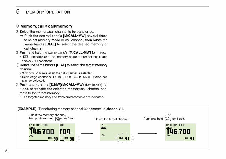


![· 430 mhz fm mobile transceiver dj-520j dual band fm handy transceiver dj-530j 144/430mhz dual band fm handy transceiver . r 10f3 r 10173] (tcxo) (tcxo) digital ej-47u ¥14,800](https://static.documents.pub/doc/80x56/604c0c10cc37c0411e3ddecf/430-mhz-fm-mobile-transceiver-dj-520j-dual-band-fm-handy-transceiver-dj-530j-144430mhz.jpg)


