Dual-beam interferometer for the accuratedetermination of surface-wave velocity
Andrew D. W. McKie, James W. Wagner, James B. Spicer, and John B. Deaton, Jr.
A novel dual-beam interferometer has been designed and constructed that enables two beams from aHe-Ne laser to probe remotely the surface of a material. The separation of the two He-Ne beams isadjustable in the 15-to- 40-mm range with a spatial resolution of 2 [um. Surface-acoustic-wavemeasurements have been performed with two different probe separations so that the travel time for thesurface waves over a known distance can be determined accurately. With the aid of autocorrelationalgorithms, the Rayleigh pulse velocity on 7075-T651 aluminum has been measured to be 2888 ± 4 m/s.The current precision of the system is limited mainly by the 10-ns sampling rate of the digital oscilloscopeused. Rayleigh pulse interactions with a surface-breaking slot, machined to a nominal depth of 0.5 mm,have also been examined and the depth estimated ultrasonically to be 0.49 ± 0.02 mm. The system mayalso provide a technique for direct quantitative studies of surface-wave attenuation.
Introduction
A number of recent papers have highlighted theimportance of determining nondestructively the pre-ferred polycrystalline grain orientation, or texture, ofa material.", The formability in a rolled sheet, forexample, is strongly influenced by the texture of thepolycrystalline metal.3 Under manufacturing condi-tions the texture ideally needs to be controlled inorder to achieve the desired material properties andto increase productivity. A promising technique hasbeen the use of ultrasonics because elastic anisotropyis correlated to texture and thus may be measuredfrom variations in the ultrasonic wave speed.
Previous techniques for determining elastic anisot-ropy have used piezoelectric transducers as genera-tors and receivers, although a number of problemsare often associated with the use of these devices. Thecontacting nature of these techniques introducesinaccuracies owing to variations in coupling efficiencyand adds an unknown acoustic impedance. Further-more, bandwidths are generally limited to a fewmegahertz. To eliminate these inaccuracies, noncon-tacting transducers such as electromagnetic acoustictransducers have been developed.4 However, withrespect to permitting accurate measurements of sur-
The authors are with the Center for Nondestructive Evaluation,The Johns Hopkins University, 102 Maryland Hall, Baltimore,Maryland 21218.
face-acoustic-wave velocity, optical techniques havean advantage in that the probe size may be made ofthe order of 10 plm in diameter, significantly reducingarrival time ambiguities.
In laser generation of ultrasound, unlike conven-tional piezoelectric ultrasonic generation, a singlelaser pulse generates a number of different ultrasonicmodes, which propagate from the irradiation loca-tion. For a point-source excitation, longitudinal andshear waves propagate into the solid with sphericalwavefronts, and Rayleigh waves propagate with acircular wave front over the solid surface. SinceRayleigh waves penetrate into the material to a depthof approximately one wavelength, when the materialthickness becomes less than the Rayleigh pulse wave-length the Rayleigh pulse couples with both sides ofthe material, and Lamb waves are generated.5 6 Ray-leigh waves are particularly important for nondestruc-tive-evaluation applications since they attenuate at alesser rate than bulk waves. Also, in aluminum 65%of the total elastic energy radiated from a thermoelas-tically generated point source is carried by the Ray-leigh pulse.'
Typically, for laser generation of ultrasound, ashort-duration pulse from a Q-switched laser is usedto generate ultrasonic transients through thermoelas-tic, ablative, or constrained surface mechanisms. Tocomplement the noncontact generation of ultra-sound various laser systems have been developed todetect remotely the laser-generated transients.9 0 Pre-viously, precise velocity measurements were made byusing bulk ultrasonic waves" since the specimen
thickness can be determined accurately through mi-crometer measurement and the propagation timebetween successive ultrasonic pulse echoes can bedetermined accurately either directly or by autocorre-lation techniques. By contrast, while the propagationtime of Rayleigh pulses may be determined accu-rately, the distance traveled can be subject to a largesource of error. One technique that helps to alleviatethis problem is the two-probe piezoelectric trans-ducer system developed by Mignogna et al." How-ever, even though the finite size of the receivertransducers is small, it is found that surface rough-ness produces substantial errors in the measuredpropagation times because the area contacted by thetransducer is slightly different at different probelocations. Also, in addition to coupling variations, thefirst transducer of the two-probe system slightlydistorts the propagating surface Rayleigh wave sothat the second receiver sees an additional phaseshift.
Previously a heterodyne fiber-optic interferometerwas for noncontact determination of surface-wavevelocity in which relative velocities could accuratelybe measured.'3 In this paper the design and implemen-tation of a dual-probe interferometer for makinghigh-accuracy absolute surface-acoustic-wave veloc-ity measurements by way of a precision differentialmeasurement are discussed, and some preliminaryexperimental data are presented.
Interferometer Description
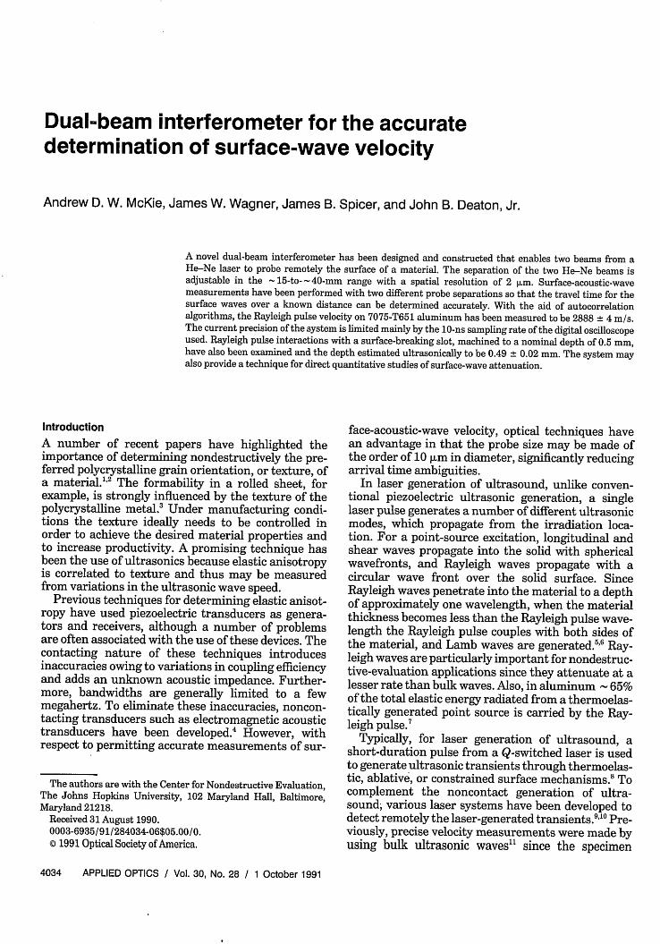
A schematic diagram of the dual-beam interferometeris shown in Fig. 1. The light source used was a 5-mWHe-Ne laser (Melles-Griot Model 05 LHP 151) operat-ing at a wavelength of 632.8 nm. The output from thelaser was linearly polarized, with the orientation setat 450 (i.e., half-way between vertical and horizontal)and was directed by mirror Ml to be incident upon a
.4-nl
X/4 PlateL
Piezoelectric/ tube
7`_O' M2
_ * 2 M3
Polarizing Piezoelectricbeamsplitter Feedback
Control
Polarizing< 3 beamsplitter
Set at 450
Photodiodes
Amplifier - /
ComputerSystem
LeCroy 9400_ digital
oscilloscope
Fig. 1. Schematic diagram of the dual-beam interferometer.
pair of polarizing beam-splitter cubes. The first beamsplitter separated the incident laser beam into twoorthogonally polarized beams, which emerged fromthe cube through adjacent faces and in directions thatwere 900 apart. The horizontally polarized componentwas transmitted through both polarizing beam split-ters to the photodetectors and formed the referencebeam of the interferometer. The vertically polarizedcomponent was reflected to the sample surface afterpropagating through a quarter-wave (X/4) plate. TheX/4 plate was oriented such that the light returningto the first beam splitter was rotated to a horizontallypolarized state and was thus transmitted through thebeam splitter. Two turning mirrors, M2 and M3,redirected the beam (which remained horizontallypolarized) so that it was transmitted through thesecond beam splitter to the sample and formed thesecond probe beam of this dual-beam interferometer.Again, two passes through a suitably oriented X/4plate rotated the polarization 900 so that the beamreturned to the second beam splitter vertically polar-ized, where it was finally reflected to the photodetec-tors. Note that when the signal and the referencebeams were recombined, they had orthogonal polariza-tions and thus did not interfere to give intensityfluctuations unless further polarizing optics wereused. To achieve the correct polarization orientationsrequired, we passed the two beams through a thirdpolarizing beam-splitter cube, which had its axes setat 450 with respect to the polarization states of thetwo incident laser beams. This resulted in the 450components of the reference and signal beams beingselected and provided two interference channels whoseoptical phases differed by 1800. Two N-type siliconp-i-n photodiodes (type RCA C30808) were used tomonitor the intensity fluctuations arising from theinterference. Electronic subtraction of the output ofthe photodetectors by phase inversion and additionyielded the output signal, which was amplified by ahigh-performance dc-coupled operational amplifier(Comlinear Corporation, type CLC E201). The ampli-fier had a voltage gain of 25 when driving a 504f loadand had a corresponding -3-dB bandwidth of 80MHz. Note that this is the bandwidth limit of theelectronic components. The actual system bandwidthfor the detection of surface waves is ultimately deter-mined by the spatial extent of the probe beams sincethe signal involves convolution over the detectionspot diameters. However, for the optical detection ofbulk waves in thick specimens the spatial extent ofthe probe beam(s) becomes less of an effect fordetection in the far field, which is most often the case.
The use of polarizing optical components provideda more efficient system since the maximum amount oflight possible was used. In many other variations ofthe Michelson interferometer, 50% of the signal andreference beams is fed back into the laser, causingfluctuations in laser intensity and giving rise tospurious interference signals. Furthermore, beam-intensity control in each path of the interferometerwas simply implemented by rotating the He-Ne laser
head, thus equalizing the dc components of the twophotocurrents. This balanced photodetection tech-nique reduced high-frequency noise resulting fromlaser relaxation oscillations and He-Ne laser powerfluctuations.'4
For large displacements of the sample surface, it ispossible to count whole numbers of fringes at thephotodetectors, with each fringe representing a sam-ple displacement of X/2, where X is the wavelength ofthe light source used. If the interferometer was stableenough that the photodetectors monitored one fringe,a measure of sample displacements less than /4could be obtained from the variation in fringe inten-sity. In practical situations, however, environmentaldisturbances such as building vibrations and airborneturbulence generate optical path-length changes thatresult in a randomly varying interference signal.These path-length changes can have amplitudes ofthe order of several micrometers (i.e., several fringes),in the 0-1-kHz frequency range. In comparison,transient ultrasonic displacements arising from alaser excitation source are typically of the order ofhundreds of picometers, representing fractional fringeshifts in the interferometer. Clearly, the interferome-ter must be stabilized against any low-frequencyextraneous mechanical and thermal effects that mayalter the optical path-length difference. In the systemdescribed here, low-frequency feedback control of theinterferometer was implemented by affixing mirrorM2 to one end of a piezoelectric tube, which wasdriven by a high-voltage feedback signal derived fromthe photodetector outputs. In this condition, forsample displacements much less than X/4 in ampli-tude, the interferometer output voltage is given by
Vo = 2rV 0 x/X, (1)
where V is the peak-to-peak voltage of the interferom-eter when the sample displacement x exceeds X/2 andX is the He-Ne laser wavelength of 632.8 nm. Hencethe interferometer voltage output may be calibratedto give absolute displacement as long as V is known.
The system of beam splitters and X/4 plates wasmounted upon a stainless-steel translation stage (New-port Model 462-X-OPT-06), which incorporated avernier micrometer providing 25 mm of linear travelwith a resolution of 1 rim. Thus, by moving the stagetoward or away from the sample, the separation ofthe two probe spots could be adjusted accuratelywithin a range of 15 to 40 mm.
Coherence Requirements
For maximum fringe visibility, the optical path lengthstraversed by the signal and reference beams must benearly equal. The allowable path-length differencedecreases as the spectral width of the light sourceincreases so that, when the interferometer is illumi-nated with light from a laser of single frequency,path-length differences of many meters can be toler-ated and good fringe visibility maintained.
However, since for single-frequency laser operation
only one mode can be allowed to oscillate in the lasercavity, the laser cavity must be short and operatedclose to threshold. Unfortunately this leads to lowlaser output power. For increased power output thecavity length can be increased and the laser operatedfurther above the threshold level. When this is done,the laser's spectral linewidth gradually increases, andseveral longitudinal modes reach threshold for laseroscillation. This results in multimode laser operation,which means that for good fringe visibility somedesign criteria must be met.
If the near-zero path-length condition cannot bemet in practice, an alternative approach that stillmaintains good fringe visibility would be to have theoptical path-length difference equal to an integermultiple of twice the laser cavity length.'5 The opticalfield distribution reproduces itself after one roundtrip in the laser resonator. Therefore constructiveinterference from all oscillating laser modes willoccur only at optical path-length differences equal to0, 2L, 4L, . . , where L is the laser cavity length. Anypositions between these will result in decreased fringevisibility, and, in the case of the optical path-lengthdifferences equal to L, 3L, 5L . . . , the fringe visibilitymay be reduced to zero since total destructive interfer-ence may occur (depending on mode distributionwithin the linewidth and on relative mode intensi-ties).'6 In this particular design the zero path-lengthcondition can never be met, so the next optimumoperating point in the system is at a path-lengthdifference of 12 cm. For convenience, however, thedevice was used at an operating distance of 29 cmfrom the specimen. Working distances greater thanthis are achievable, although the divergence of theHe-Ne beam may be a problem unless focusing opticsare used.
Experimental Arrangement
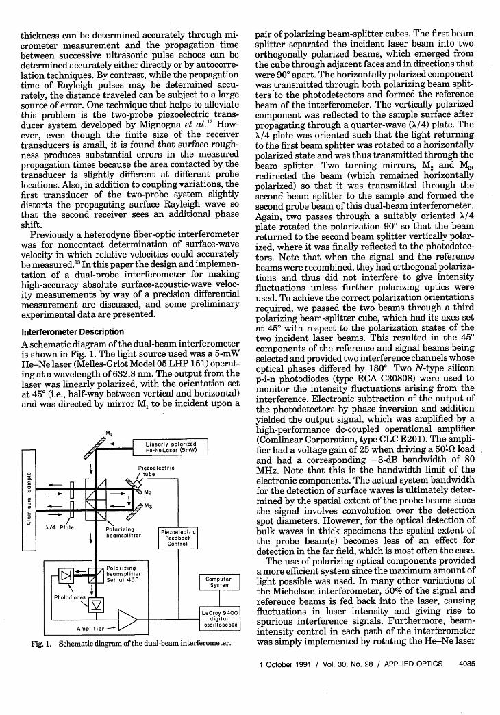
Figure 2 is a schematic diagram of the experimentalconfiguration. Rayleigh pulse generation was imple-mented by irradiating the surface of the material withlaser pulses from an air-cooled Q-switched Nd:YAG
Q-switched Nd:YAGlaser pulse (l8mJ,4ns) He-Ne laser beams from
I I I dual-probe interferomete
120 X 70 65mm Artificial crack0.50 mm deep X 0.1 mm wide
Fig. 2. Schematic diagram of the experimental configuration.
laser (Kigre, Inc.). The typical pulse energies fromthis laser were 18 mJ in a 4-ns pulse duration. Abiconvex lens was used in these experiments to focusthe laser beam to a small-diameter spot so thatultrasonic generation was in the ablative regime. Alsodepicted in the diagram are two He-Ne laser beams,which emanate from the dual-probe interferometerand monitor the surface displacements. All wave-forms were recorded on a LeCroy 9400 digital oscillo-scope and stored on computer for subsequent analy-sis. The sample used was a 120 mm x 70 mm x 65mm block of 7075-T651 aluminum. The dimensionswere chosen to ensure that sidewall surface-wave andbulk reflections would not obscure the signal ofinterest.
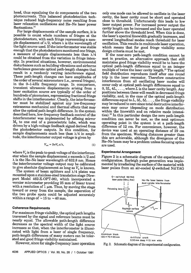
First, consider the case in which the Rayleigh pulsepropagates across an unflawed section of material.The resultant waveforms are displayed in Fig. 3. Theprobe beam separation was initially set at 15 mmfor the first measurement [Fig. 3(a)] and then accu-rately increased by 25 mm 2 um to produce thesecond waveform [Fig. 3(b)] by traversing the beam-splitter assembly. Both waveforms clearly show thepresence of two large-amplitude pulses, R, and R2,and are characteristic of laser-generated Rayleigh
(a) 4.0
z0
(12
2.0 -
0.0 -
-2.0 -
-4.0 -
-6.0 -
-8.0 -_0.0
( b) 4 .0 _
02.0-
<0.0IE-z> -2.0¢
W -4.0
-6.0
-8.0 -_
. . . . . ...5.0 10.0TIME /([us)
15.0 20.0
.0 5.0 10.0 15.0 20.0TIME /( s)
Fig. 3. Laser-generated Rayleigh pulses detected with the dual-beam interferometer. The beam separation has been increased by25 mm ± 0.02 pm from (a) to (b).
pulses. These two pulses are the result of the singlelaser-generated Rayleigh pulse passing beneath thefirst probe' spot and continuing to propagate underthe second detection spot. The low-amplitude pulse,P, which arrives first, is the surface-skimming longi-tudinal wave and is so highly attenuated that it is notdetected at the second probe spot in either case. Notethat in both cases the second Rayleigh pulse ampli-tude is less than the first, as expected, because ofattenuation over the extra propagation distance tothe second probe spot. The time for the Rayleighpulse to travel between the two probe spots wascalculated for both waveforms by using an autocorre-lation procedure, with the difference in these twotimes being the time taken for the Rayleigh pulse totravel 25 mm ± 2 pm; see Fig. 3. This measurementwas repeated in the orthogonal propagation direction,and the resulting velocities were 2888 + 4 and 2882 +4 ms/s, which compare well with the handbook valuefor 7075-T651 aluminum, which is 2883 m/s.'7 Differ-ences in the velocity may result from weak anisot-ropy, although the error bounds overlap. The mainsource of error is dominated by an order of magnitudeby the 10-ns sampling rate, which could be surpassedwith an interpolation technique" or by using a fasterdigitizer.
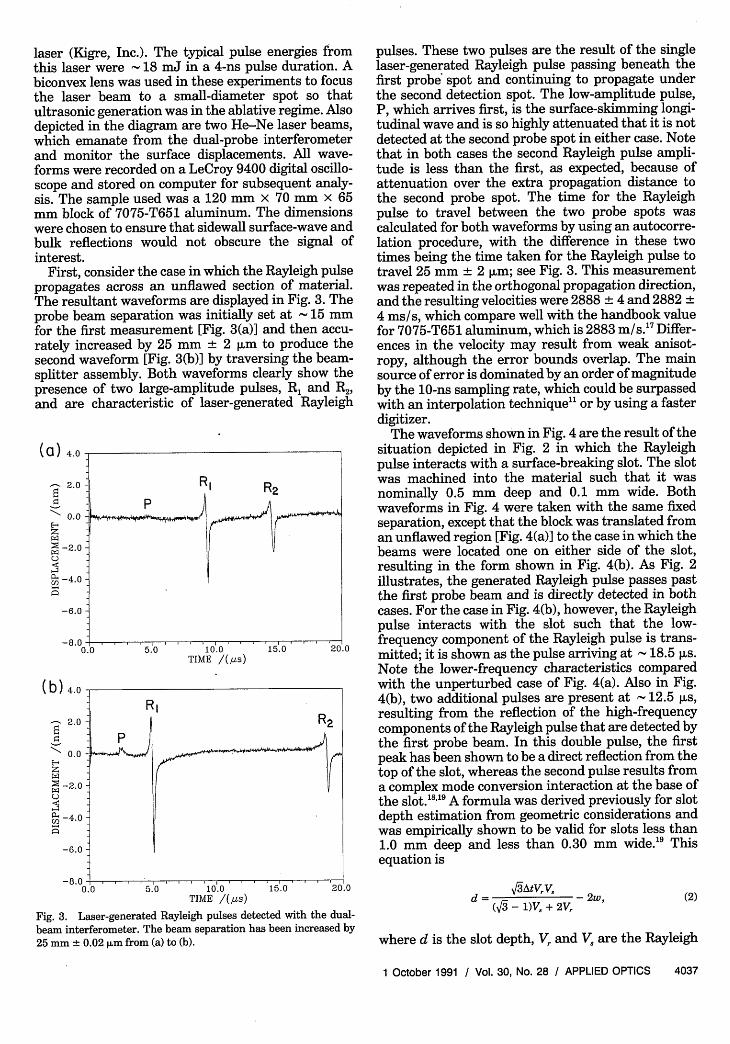
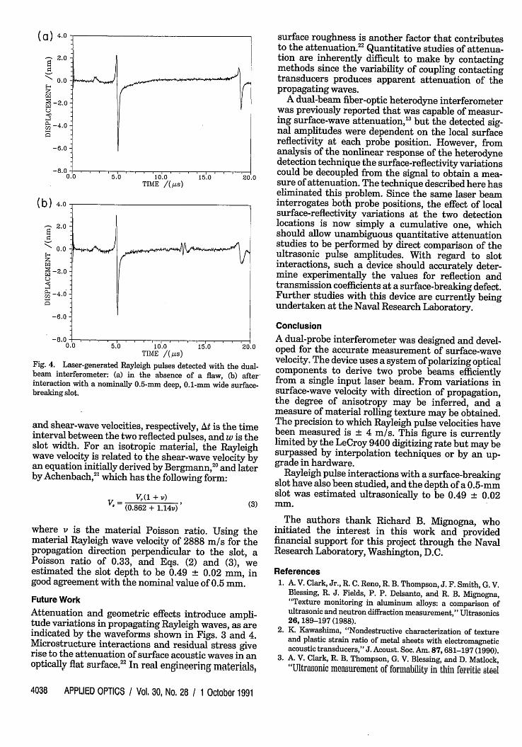
The waveforms shown in Fig. 4 are the result of thesituation depicted in Fig. 2 in which the Rayleighpulse interacts with a surface-breaking slot. The slotwas machined into the material such that it wasnominally 0.5 mm deep and 0.1 mm wide. Bothwaveforms in Fig. 4 were taken with the same fixedseparation, except that the block was translated froman unflawed region [Fig. 4(a)] to the case in which thebeams were located one on either side of the slot,resulting in the form shown in Fig. 4(b). As Fig. 2illustrates, the generated Rayleigh pulse passes pastthe first probe beam and is directly detected in bothcases. For the case in Fig. 4(b), however, the Rayleighpulse interacts with the slot such that the low-frequency component of the Rayleigh pulse is trans-mitted; it is shown as the pulse arriving at 18.5 us.Note the lower-frequency characteristics comparedwith the unperturbed case of Fig. 4(a). Also in Fig.4(b), two additional pulses are present at 12.5 ps,resulting from the reflection of the high-frequencycomponents of the Rayleigh pulse that are detected bythe first probe beam. In this double pulse, the firstpeak has been shown to be a direct reflection from thetop of the slot, whereas the second pulse results froma complex mode conversion interaction at the base ofthe slot.'" 9 A formula was derived previously for slotdepth estimation from geometric considerations andwas empirically shown to be valid for slots less than1.0 mm deep and less than 0.30 mm wide.'9 Thisequation is
(2)d= 3AtVVs _ 2w,(V3 - 1)V. + 2V,
where d is the slot depth, V, and V. are the Rayleigh
Fig. 4. Laser-generated Rayleigh pulses detected with the dual-beam interferometer: (a) in the absence of a flaw, (b) afterinteraction with a nominally 0.5-mm deep, 0.1-mm wide surface-breaking slot.
and shear-wave velocities, respectively, At is the timeinterval between the two reflected pulses, and w is theslot width. For an isotropic material, the Rayleighwave velocity is related to the shear-wave velocity byan equation initially derived by Bergmann,20 and laterby Achenbach,2' which has the following form:
V. V ( + V) (3)(0.862 + 1.14v)
where v is the material Poisson ratio. Using thematerial Rayleigh wave velocity of 2888 m/s for thepropagation direction perpendicular to the slot, aPoisson ratio of 0.33, and Eqs. (2) and (3), weestimated the slot depth to be 0.49 0.02 mm, ingood agreement with the nominal value of 0.5 mm.
Future Work
Attenuation and geometric effects introduce ampli-tude variations in propagating Rayleigh waves, as areindicated by the waveforms shown in Figs. 3 and 4.Microstructure interactions and residual stress giverise to the attenuation of surface acoustic waves in anoptically flat surface, In real engineering materials,
surface roughness is another factor that contributesto the attenuation.22 Quantitative studies of attenua-tion are inherently difficult to make by contactingmethods since the variability of coupling contactingtransducers produces apparent attenuation of thepropagating waves.
A dual-beam fiber-optic heterodyne interferometerwas previously reported that was capable of measur-ing surface-wave attenuation, but the detected sig-nal amplitudes were dependent on the local surfacereflectivity at each probe position. However, fromanalysis of the nonlinear response of the heterodynedetection technique the surface-reflectivity variationscould be decoupled from the signal to obtain a mea-sure of attenuation. The technique described here haseliminated this problem. Since the same laser beaminterrogates both probe positions, the effect of localsurface-reflectivity variations at the two detectionlocations is now simply a cumulative one, whichshould allow unambiguous quantitative attenuationstudies to be performed by direct comparison of theultrasonic pulse amplitudes. With regard to slotinteractions, such a device should accurately deter-mine experimentally the values for reflection andtransmission coefficients at a surface-breaking defect.Further studies with this device are currently beingundertaken at the Naval Research Laboratory.
Conclusion
A dual-probe interferometer was designed and devel-oped for the accurate measurement of surface-wavevelocity. The device uses a system of polarizing opticalcomponents to derive two probe beams efficientlyfrom a single input laser beam. From variations insurface-wave velocity with direction of propagation,the degree of anisotropy may be inferred, and ameasure of material rolling texture may be obtained.The precision to which Rayleigh pulse velocities havebeen measured is 4 m/s. This figure is currentlylimited by the LeCroy 9400 digitizing rate but may besurpassed by interpolation techniques or by an up-grade in hardware.
Rayleigh pulse interactions with a surface-breakingslot have also been studied, and the depth of a 0.5-mmslot was estimated ultrasonically to be 0.49 0.02mm.
The authors thank Richard B. Mignogna, whoinitiated the interest in this work and providedfinancial support for this project through the NavalResearch Laboratory, Washington, D.C.
References1. A. V. Clark, Jr., R. C. Reno, R. B. Thompson, J. F. Smith, G. V.
Blessing, R. J. Fields, P. P. Delsanto, and R. B. Mignogna,"Texture monitoring in aluminum alloys: a comparison ofultrasonic and neutron diffraction measurement," Ultrasonics26, 189-197 (1988).
2. K. Kawashima, "Nondestructive characterization of textureand plastic strain ratio of metal sheets with electromagneticacoustic transducers," J. Acoust. Soc. Am. 87,681-197 (1990).
3. A. V. Clark, R. B. Thompson, G. V. Blessing, and D. Matlock,"Ultrasonic manuromont of formability in thin ferritic steel
sheet," in Review of Progress in Quantitative NondestructiveEvaluation, D. 0. Thompson and D. E. Chimenti, eds. (Ple-
num, New York, 1988), Vol. 8A, p. 1031.
4. H. M. Frost, "Electromagnetic-ultrasound transducers: prin-ciples, practice, and applications," in Physical Acoustics, W. P.Mason and R. N. Thurston, eds. (Academic, New York, 1979),
Vol. XIV, p. 179.5. R. J. Dewhurst, C. Edwards, A. D. W. McKie, and S. B. Palmer,
"Estimation of the thickness of thin metal sheet using lasergenerated ultrasound," Appl. Phys. Lett 51, 1066-1068 (1987).
6. J. B. Spicer, A. D. W. McKie, and J. W. Wagner, "Quantitative
theory for laser ultrasonic waves in a thin plate," Appl. Phys.Lett. 57, 1882-1884 (1990).
7. L. R. F. Rose, "On the energy radiated by Rayleigh waves,"
Wave Motion 6, 359-361 (1984).
8. D. A. Hutchins, "Ultrasonic generation by pulsed lasers," in
Physical Acoustics, W. P. Mason and R. N. Thurston, eds.
(Academic, London, 1988), Vol. XVIII, p. 21.
9. J.-P. Monchalin, "Optical detection of ultrasound," IEEETrans. Ultrason. Ferroelectrics Freq. Control UFFC-33, 485-499 (1986).
10. J. W. Wagner, "Optical detection of ultrasound," in PhysicalAcoustics, W. P. Mason and R. N. Thurston, eds. (Academic,
New York, 1990), Vol. XIX, p. 201.
11. J.-D. Aussel and J.-P Monchalin, "Precision laser-ultrasonicvelocity measurement and elastic constant determination,"Ultrasonics 27, 165-177 (1989).
12. R. B. Mignogna, P. P. Delsanto, A. V. Clark, Jr., B. B. Rath,
and C. L. Vold, "Ultrasonic texture analysis for polycrystallineaggregates of cubic materials displaying orthotropic symme-try," in Nondestructive Characterization of Materials II, J. F.Bussiere, J.-P. Monchalin, C. 0. Ruud, and R. E. Green, Jr.,eds. (Plenum, New York, 1987), p. 535.
13. J. B. Spicer and J. W. Wagner, "Fiber-optic based heterodyneinterferometer for noncontact ultrasonic determination ofacoustic velocity and attenuation in materials," inNondestruc-tive Characterization of Materials, P. Holler, V. Hauk, G.Dobmann, C. Ruud, and R. E. Green, eds. (Springer-Verlag,Berlin, 1989), p. 691.
14. C. H. Palmer, "Circumventing laser relaxation oscillations ininterferometers," Appl. Opt. 23, 3510-3512 (1984).
15. L. E. Drain, J. H. Speake, and B. C. Moss, "Displacement and
vibration measurement by laser interferometry," in FirstEuropean Congress on Optics Applied to Metrology, M. Gross-man and P. Meyrueis, eds., Proc. Soc. Photo-Opt. Instrum.Eng. 136,52-59 (1977).
16. J. W. Foreman, Jr., "Optical path-length difference effects inphotomixing with multimode gas laser radiation," Appl. Opt.6, 821-826 (1967).
17. Richard Stiffler, Alcoa, Pittsburgh, Pa. (personal communica-tion).
18. A. D. W. McKie, "Applications of laser generated ultrasound
using an interferometric sensor," Ph.D. dissertation (Univer-sity of Hull, Hull, UK 1987).
19. J. A. Cooper, R. A. Crosbie, R. J. Dewhurst, A. D. W. McKie,
and S. B. Palmer, "Surface acoustic wave interaction withcracks and slots: a noncontacting study using lasers," IEEETrans. Ultrason. Ferroelectrics Freq. Control UFFC-33, 462-470 (1986).
20. L. Bergmann, Der Ultraschall und seine Anwendung inWissenschaft und Technik (Hirzel-Verlag, Stuttgart, 1954), p.560.
21. J. D. Achenbach, Wave Propagation in Elastic Solids (NorthHolland, Amsterdam, 1973), p. 192.
22. M. de Billy, G. Quentin, and E. Baron, "Attenuation measure-
ments of an ultrasonic Rayleigh wave propagating along roughsurfaces," J. Appl. Phys. 61, 2140-2145 (1987).