Page 1
N
W E
S
N
W E
SSpecified Fittings
Mailing AddressSpeci�ed Fittings
PO Box 28157Bellingham, WA 98228-0157
Washington LocationSpeci�ed Fittings
164 W. Smith Rd. | Bellingham, WA 98226-9616
360-398-7700 | 360-398-7051 Fax
Montana LocationSpeci�ed Fittings
483 Airport Rd. | Stevensville, MT 59870-6363
406-777-3466 | 406-777-7181 Fax
Mexico800-429-1705 Toll Free
800-574-1075 Fax
www.speci�ed�ttings.com sales@spec�t.com
DUAL CO
NTAIN
MEN
TPV
C IPS - PVC C900 - CPV
C IPS - HD
PE IPS - HD
PE DIPS
Page 2
Terms And Conditions Of Sale These Terms and Conditions govern all purchases from Specified Fittings, Inc. (SFI)
1) Shipping and Delivery. All materials shipped FOB our plant in Bellingham, Washington or a regional distribution warehouse, unless otherwise specified herein. On PVC and CPVC orders, freight will be paid on $1500.00 net orders. HDPE orders are FOB Factory of origin. On drain basins and in-line drains, freight will be paid on orders over $2000.00, with the exception of basin/drains over 30” diameter and 78” over all length. These are FOB factory. These freight terms exclude all pipe and are for shipments to one location within the contiguous forty-eight (48) states. All claims for lost and/or damaged merchandise shall be made by the Buyer to the delivery carrier.
2) Specifically Manufactured Goods. All fabricated fittings or special order items may not be canceled or returned. 3) Inspection and Returns. Buyer will inspect all material at time of delivery and note on the Bill Of Lading any apparent defects. Buyer
waives all rights to reject nonconforming goods with visible defects if they fail to note the rejected goods on the Bill Of Lading. Goods will not be accepted for return without a returned goods authorization (RGA) issued by SFI. A restocking fee and inbound freight charges will be assessed on all material returned to SFI. Where appropriate, outbound freight costs will also be assessed. Goods must be returned in clean condition and SFI count of returned material shall be deemed final. Special fittings and unreasonably large quantities are not returnable.
4) Payment and Taxes. All orders shall be prepaid, or at SFI’s option, SFI will mail invoices to Buyer. Invoice amounts are due and payable by the 10th day following date of invoice. Any trade discount in effect at any particular time and applicable to the transaction will be revoked if timely payment is not received. Purchases and shipments made after the 25th of the month will be considered the following month’s purchases. Payments not received by the end of the month following date of invoice are subject to a finance charge commencing at the end of the month in which the invoice is due. Buyer agrees to pay a finance charge of 1 ½% per month (18% annual rate) on all past due invoices. Once Buyer accepts shipment of the goods, they are obligated to make the agreed payments to SFI regardless of when and whether Buyer receives payment from someone else for the goods. Prices for sales of goods shipped outside of Washington do not include any sales or use taxes. SFI conducts business only in Washington State, and does not collect or pay the taxes of any other State.
5) Warranties. SFI warrants all new products against defects resulting from faulty workmanship or materials for a period of one year after the date of the original purchase. SFI will repair or replace, at its option, any product established to be so defective, with a product of like type. CLAIMS FOR LABOR COSTS AND OTHER CHARGES RESULTING FROM THE USE OF SFI GOODS AND/OR PRODUCTS ARE NOT COVERED BY THIS LIMITED WARRANTY. This limited warranty is effective only for the benefit of the original Buyer and user provided the following procedure is followed. FAILURE TO ADHERE TO THE REQUIREMENTS OUTLINED BELOW WILL INVAILIDATE THE TERMS OF THE LIMITED WARRANTY.
a. Within thirty (30) days after noticing the defect, Buyer/User must notify SFI, in writing, at its corporate offices located at 164 West Smith Road, P.O. Box 28157, Bellingham, Washington 98226, of all alleged defects.
b. Upon request by SFI, Buyer/User must either return the defective fitting(s) to SFI; freight prepaid, or at the option of SFI, makes the defective fitting(s) available for inspection by SFI, or its designee. If the product is found to be defective because of a manufacturing error, the freight cost will be reimbursed.
c. After SFI repairs and/or replaces product, it will ship the product to the Buyer/User, freight prepaid. d. Any modifications of our fittings makes this warranty void.
SFI DISCLAIMS ALL EXPRESS WARRANTIES OTHER THAN THOSE CONTAINED IN THE ABOVE PARAGRAPH, AND ALL IMPLIED WARRANTIES, INCLUDING BUT NO LIMITED TO WARRANTIES OF MERCHANTABILITY AND FITNESS FOR A PARTICULAR PURPOSE. THERE ARE NO WARRANTIES THAT EXTEND BEYOND THE DESCRIPTION ON THE FACE HEREOF, SFI SHALL NOT BE LIABLE FOR SPECIAL, INDIRECT, INCIDENTAL OR CONSEQUENTIAL DAMAGES OF ANY KIND, INCLUDING BUT NOT LIMITED TO LOST PROFIT, BUSINESS INTERRUPTION LOSSES, LOSS OF GOODWILL, OR LOSS OF BUSINESS OR CUSTOMER RELATIONSHIPS. Some states do not allow the exclusion of implied warranties or the limitation or exclusion of liability for incidental or consequential damages, so the above exclusion or limitation may not apply to the Buyer. This warranty gives Buyer specific legal rights and Buyer may also have other rights that vary from state to state. In the event that a dispute arises, the parties agree that independent third party testing of the alleged defective product shall be conducted and all costs in connection with such testing shall be borne by the party proved incorrect in the allegation pursuant to the results of the third party tester.
6) Indemnification. Buyer will indemnify SFI against, and save SFI harmless from, any and all claims, suits or liability arising from injuries to property or persons, including death, and from any other claims, suits or liability on account of any negligent or intentional act or omission of Buyer or any of Buyer’s officers, agents, employees or servants.
7) Litigation. In any case of litigation between the parties concerning this Agreement and Conditions of Sale, including trial and appellate proceedings, venue shall be in the State of Washington, County of Whatcom, and the laws of the State of Washington will apply to any dispute. Reasonable attorney’s fees shall be awarded to the prevailing party. These conditions of sale will not in any way be construed to limit or restrict SFI’s rights and remedies at law and in equity, all of which rights and remedies SFI fully reserves, unless such limitations are specifically stated. Any failure or forbearance by SFI to enforce any of the conditions of sale of this Contract or any of SFI’s rights and remedies at law or in equity shall not constitute a waiver or relinquishment by SFI of any of SFI’S rights and remedies under this Contract.
8) Assignment, Amendment, Modification. Neither Party shall assign its rights and duties under this Contract without the other’s prior written consent. These Terms and Conditions may only be amended or modified in writing signed by both parties. This Purchase Order and Sales Agreement and these Terms and Conditions, including all writings attached hereto or incorporated by reference, are intended to be final, complete and exclusive statement of the terms of the parties’ agreement. Notice is hereby given pursuant to the Uniform Commercial Code as adopted by any State, of SFI’s objection to all terms and conditions in addition to and different from the condition of sale contained herein that Buyer may add to this Contract or place in any written conformation or purchase order that Buyer may issue, unless the parties agree to any added or different terms in writing.
9) Any of the Conditions of Sale herein that may conflict with the normal operation of any provision of the Uniform Commercial Code will constitute a variation by agreement and have precedence.
Page 3
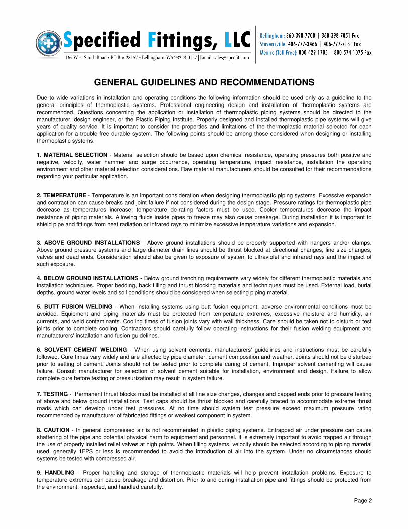
GENERAL GUIDELINES AND RECOMMENDATIONS
Due to wide variations in installation and operating conditions the following information should be used only as a guideline to the
general principles of thermoplastic systems. Professional engineering design and installation of thermoplastic systems are
recommended. Questions concerning the application or installation of thermoplastic piping systems should be directed to the
manufacturer, design engineer, or the Plastic Piping Institute. Properly designed and installed thermoplastic pipe systems will give
years of quality service. It is important to consider the properties and limitations of the thermoplastic material selected for each
application for a trouble free durable system. The following points should be among those considered when designing or installing
thermoplastic systems:
1. MATERIAL SELECTION - Material selection should be based upon chemical resistance, operating pressures both positive and
negative, velocity, water hammer and surge occurrence, operating temperature, impact resistance, installation the operating
environment and other material selection considerations. Raw material manufacturers should be consulted for their recommendations
regarding your particular application.
2. TEMPERATURE - Temperature is an important consideration when designing thermoplastic piping systems. Excessive expansion
and contraction can cause breaks and joint failure if not considered during the design stage. Pressure ratings for thermoplastic pipe
decrease as temperatures increase; temperature de-rating factors must be used. Cooler temperatures decrease the impact
resistance of piping materials. Allowing fluids inside pipes to freeze may also cause breakage. During installation it is important to
shield pipe and fittings from heat radiation or infrared rays to minimize excessive temperature variations and expansion.
3. ABOVE GROUND INSTALLATIONS - Above ground installations should be properly supported with hangers and/or clamps.
Above ground pressure systems and large diameter drain lines should be thrust blocked at directional changes, line size changes,
valves and dead ends. Consideration should also be given to exposure of system to ultraviolet and infrared rays and the impact of
such exposure.
4. BELOW GROUND INSTALLATIONS - Below ground trenching requirements vary widely for different thermoplastic materials and
installation techniques. Proper bedding, back filling and thrust blocking materials and techniques must be used. External load, burial
depths, ground water levels and soil conditions should be considered when selecting piping material.
5. BUTT FUSION WELDING - When installing systems using butt fusion equipment, adverse environmental conditions must be
avoided. Equipment and piping materials must be protected from temperature extremes, excessive moisture and humidity, air
currents, and weld contaminants. Cooling times of fusion joints vary with wall thickness. Care should be taken not to disturb or test
joints prior to complete cooling. Contractors should carefully follow operating instructions for their fusion welding equipment and
manufacturers' installation and fusion guidelines.
6. SOLVENT CEMENT WELDING - When using solvent cements, manufacturers' guidelines and instructions must be carefully
followed. Cure times vary widely and are affected by pipe diameter, cement composition and weather. Joints should not be disturbed
prior to setting of cement. Joints should not be tested prior to complete curing of cement, Improper solvent cementing will cause
failure. Consult manufacturer for selection of solvent cement suitable for installation, environment and design. Failure to allow
complete cure before testing or pressurization may result in system failure.
7. TESTING - Permanent thrust blocks must be installed at all line size changes, changes and capped ends prior to pressure testing
of above and below ground installations. Test caps should be thrust blocked and carefully braced to accommodate extreme thrust
roads which can develop under test pressures. At no time should system test pressure exceed maximum pressure rating
recommended by manufacturer of fabricated fittings or weakest component in system.
8. CAUTION - In general compressed air is not recommended in plastic piping systems. Entrapped air under pressure can cause
shattering of the pipe and potential physical harm to equipment and personnel. It is extremely important to avoid trapped air through
the use of properly installed relief valves at high points. When filling systems, velocity should be selected according to piping material
used, generally 1FPS or less is recommended to avoid the introduction of air into the system. Under no circumstances should
systems be tested with compressed air.
9. HANDLING - Proper handling and storage of thermoplastic materials will help prevent installation problems. Exposure to
temperature extremes can cause breakage and distortion. Prior to and during installation pipe and fittings should be protected from
the environment, inspected, and handled carefully.
Page 2
Page 4
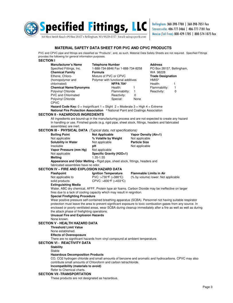
SECTION I
Manufacturer’s Name Telephone Number Address
Specified Fittings, Inc. 1-888-734-8846 Fax 1-888-734-8258
Chemical Family Formula
Mixture of PVC or CPVC Trade Designation
Polymer with functional additives HMIS²
NFPA 704¹ Health: 1
Chemical Name/Synonyms Health: 1 Flammability: 1
Polyvinyl Chloride Flammability: 1 Reactivity: 0
PVC and Chlorinated Reactivity: 0
Polyvinyl Chloride Special: None
CPVC
Hazard Code Key: 0 = Insignificant 1 = Slight 2 = Moderate 3 = High 4 = Extreme
National Fire Protection Association ² National Paint and Coatings Association
SECTION II - HAZARDOUS INGREDIENTS
SECTION III - PHYSICAL DATA (Typical data, not specifications)
Boiling Point Not Applicable Vapor Density (Air=1)
Not applicable % Volatile by Weight Not applicable
Solubility in Water Not applicable Particle Size
Insoluble pH Not applicable
Vapor Pressure (mm Hg) Not applicable
Not applicable Specific Gravity (H2O=1)
Melting 1.35-1.55
SECTION IV – FIRE AND EXPLOSION HAZARD DATA
Flashpoint Ignition Temperature Flammable Limits in Air
PVC: >730°F (>388°C) (% by volume) lower: Not applicable
CPVC: >830°F (>433°C)
Extinguishing Media
Special Firefighting Procedure
Unusual Fire and Explosion Hazards
None known.
SECTION V - HEALTH HAZARD DATA
Threshold Limit Value
None established.
Effects of Overexposure
There are no significant hazards from vinyl compound at ambient temperature.
SECTION VI - REACTIVITY DATA
Stability
Stable
Hazardous Decomposition Products
Incompatibility (materials to avoid)
Refer to Chemical charts.
SECTION VII -TRANSPORTATION
Wear positive pressure self-contained breathing apparatus (SCBA). Personnel not having suitable respirator
protection must leave the area to prevent significant exposure to toxic combustion gases from any source. In
enclosed or poorly ventilated areas, wear SCBA during cleanup immediately after a fire as well as well as during
the attack phase of firefighting operations.
CO, CO2 hydrogen chloride and small amounts of benzene and aromatic and hydrocarbons. CPVC may also
contribute small amounts of Chloroform and carbon tetrachloride.
All ingredients are bound-up in the manufacturing process and are not expected to create any hazard
In handling or use. Finished goods (e.g. rigid pipe, sheet stock, fittings, headers and fabricated
assemblies) are inert.
These products are not designated as hazardous.
Not applicable to
solid products
Water, ABC dry chemical, AFFF. Protein type air foams. Carbon Dioxide may be ineffective on larger
fires due to a lack of cooling capacity which may result in reignition.
Appearance and Odor Melting - Rigid pipe, sheet stock, fittings, headers and
fabricated assemblies have no odor.
PVC and CPVC pipe and fittings are classified as “Products”, and, as such, Material Data Safety Sheets are not required. Specified Fittings
provides the following for general information purposes.
Ethene, Chloro-
(homopolymer and
chlorinated)
PO Box 28157, Bellingham,
WA 98228
MATERIAL SAFETY DATA SHEET FOR PVC AND CPVC PRODUCTS
Page 3
Page 5
Outside
Diameter MIN Wall ID LBS/FT PSI MIN Wall ID LBS/FT PSI
3.500" .300" 2.864" 1.96 370 .216" 3.042" 1.409 260
4.500" .337" 3.8786" 2.87 320 .237" 3.998" 2.006 220
5.563" .375" 4.768" 4.02 290 .258" 5.017" 2.726 190
6.625" .432" 5.708" 5.48 280 .280" 6.031" 3.535 180
8.625" .500" 7.565" 8.32 250 .322" 7.943" 5.305 160
10.75" .593" 9.493" 12.35 230 .365" 9.976" 7.532 140
12.75" .687" 11.294" 16.98 230 .406" 11.890" 9.949 130
14.00" .750" 12.412" 20.34 220 .438" 13.072" 11.81 130
16.00" .843" 14.224" 26.03 220 .500" 14.940" 15.416 130
Temperature Temperature Design Factor
°F °C Factor
73 23. 1.
80 26.5 .88
90 32.2 .75
100 38. .62
110 43.5 .5
130 54.5 .31
PVC not recommended for service
Temperatures over 140° F ( 56.5° C )
(DT) = Temperature variation in degrees Fahrenheit
.000348 = Thermal expansion coefficient in inches/foot/°F
DL = (.0000348 x L) x DT
The following formula may be used to compute approximate
expected expansion and contraction (DL) for PVC pipe.:
PVC Schedule 80 PVC Schedule 40
Working Temperature De-Rating
If operating or ambient temperatures are expected to exceed
73°F the working pressure of PVC must be de-rated. When
exposed to elevated temperatures thermoplastic pipe stiffness
and tensile strength decrease. This decrease results in a drop
in pressure capacity. Use the chart at left to determine the
pipe's maximum pressure rating at elevated temperatures by
multiplying the pipe pressure rating at 73°F by the de-rating
factor. The result will equal the maximum pressure at elevated
working temperature. maximum temperature variation
exceeds 306°F the installation of expansion loops, offsets or
bends is recommended. Maximum temperature variation (is
calculated by comparing lowest and highest ambient or
operating temperatures to the installation temperature. For
example, a system installed at (DT) is calculated by
comparing lowest and highest ambient or operating
temperatures to the installation temperature. For example, a
system installed at 50° F having an expected operational
temperature range of 32° F to 130° F has an expected
POLY (VINYL CHLORIDE) PVC PIPE DATA
There are additional sizes and diameters of PVC pipe available. Pipe sizes not shown on the above chart include SDR 26
NSF rated to 160 PSI and SDR 21 Rated to 200 PSI . All pipe pressure ratings are for water at 73°F. For other fluids and
service temperatures ratings will differ. Appropriate adjustments must be made. Pressure ratings are for straight lengths of
pipe only. Fabricated fittings are degraded by configuration and method of fabrication.
The above PVC pressure pipe is extruded from compounds which meet the specifications of ASTM D 1784 for Type 1
Grade 1 PVC. Schedule 40 and 80 PVC pipe meet the specifications of ASTM 1785. Pressure rated SDR PVC pipe meets
ASTM D 2241, and Is NSF approved.
Proper design and installation are essential elements for successful systems. Pipe manufacturer should be consulted
when selecting piping materials.
Page 4
Page 6
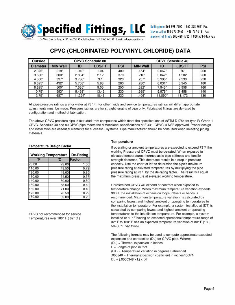
Outside
Diameter MIN Wall ID LBS/FT PSI MIN Wall ID LBS/FT PSI
2.375" .218" 1.913" 1.04 400 .154" 2.067" .761 260
3.500" .300" 2.864" 2.12 370 .216" 3.042" 1.502 260
4.500" .337" 3.786" 3.1 320 .237" 3.998" 2.239 220
6.625" .432" 5.708" 5.93 280 .280" 6.031" 3.945 180
8.625" .500" 7.565" 9.05 250 .322" 7.943" 5.958 160
10.75" .593" 9.493" 13.43 230 .365" 9.976" 8.458 140
12.75" .687" 11.294" 18.46 230 .406" 11.890" 11.172 130
Temperature Temperature Design Factor
°F °C Factor
73.00 23.00 1.00
110.00 43.50 0.72
120.00 49.00 0.65
130.00 54.50 0.57
140.00 60.00 0.50
150.00 65.50 0.42
160.00 71.00 0.40
170.00 76.50 0.29180.00 82.00 0.25
CPVC not recommended for service
Temperatures over 180° F ( 82° C )
(DL) = Thermal expansion in inches
L = Length of pipe in feet
(DT) = Temperature variation in degrees Fahrenheit
.000348 = Thermal expansion coefficient in inches/foot/°F
DL = (.0000348 x L) x DT
The following formula may be used to compute approximate expected
expansion and contraction (DL) for CPVC pipe. Where:
CPVC (CHLORINATED POLYVINYL CHLORIDE) DATA
If operating or ambient temperatures are expected to exceed 73°F the
working Pressure of CPVC must be de-rated. When exposed to
elevated temperatures thermoplastic pipe stiffness and tensile
strength decrease. This decrease results in a drop in pressure
capacity. Use the chart at left to determine the pipe's maximum
pressure rating at elevated temperatures by multiplying the pipe
pressure rating at 73°F by the de-rating factor. The result will equal
the maximum pressure at elevated working temperature.
Unrestrained CPVC will expand or contract when exposed to
temperature change. When maximum temperature variation exceeds
306°F the installation of expansion loops, offsets or bends is
recommended. Maximum temperature variation (is calculated by
comparing lowest and highest ambient or operating temperatures to
the installation temperature. For example, a system installed at (DT) is
calculated by comparing lowest and highest ambient or operating
temperatures to the installation temperature. For example, a system
installed at 50° F having an expected operational temperature range of
32° F to 130° F has an expected temperature variation of 80° F (130-
50=80° F variation).
CPVC Schedule 80 CPVC Schedule 40
All pipe pressure ratings are for water at 73° F. For other fluids and service temperatures ratings will differ; appropriate
adjustments must be made. Pressure ratings are for straight lengths of pipe only. Fabricated fittings are de-rated by
configuration and method of fabrication.
The above CPVC pressure pipe is extruded from compounds which meet the specifications of ASTM D1784 for type IV Grade 1
CPVC. Schedule 40 and 80 CPVC pipe meets the dimensional specifications of F 441. CPVC is NSF approved. Proper design
and installation are essential elements for successful systems. Pipe manufacturer should be consulted when selecting piping
materials.
Working Temperature De-Rating
Page 5
Page 7
Solvent Cement Guidelines Solvent cementing is the preferred method for joining PVC and CPVC materials in the field. The solvent
cement dissolves the surfaces of pipe and fittings to form a continuous bond between the mating surfaces and
produces an actual chemical bond between the items to be joined. It has been shown that the single most
significant cause of system failure is improper joints. Properly installed cement joints produce strong pressure-
tight joints, enhancing the integrity of a well designed piping system.
There are many types of cements and primers on the market. The various cements are designed to be used in
a variety of conditions or with certain pipe sizes or materials. It is extremely important that as much care and
consideration is given to the selection of the proper solvent cement as is to the selection of the pipe, valves,
fittings and other components of the system.
The following information, based on ASTM D 2855, is meant to be used as a general overview of the cement
process. It is critical to the success of each installation that the installing contractor be experienced and
knowledgeable in the installation of solvent cement joints. The cement manufacturers' guidelines and
recommendations should also be followed. These instructions are based on normal installation and cannot
cover every combination of conditions. Cement manufacturer should be consulted for specific
recommendations for extreme or unusual conditions.
1. SQUARE CUT PIPE - The pipe should be square cut with the axis, using a fine toothed blade. Care
should be taken to remove all burrs and/or ridges left on the end of the pipe. The cut end of the pipe should be
chamfered and deburred to prevent removal of cement and softened material which will result in a leaking
fitting.
6. TESTING - NEVER TEST SYSTEMS WITH COMPRESSED AIR OR GASSES. Extreme care should be
taken to assure complete venting of entrapped air when filling the system with water or other liquids used for
testing. Prior to testing, systems must be fully blocked, vented and air must be bled from the system. Improper
testing or installation, especially poor cementing technique and/or entrapped air, may result in catastrophic
failure. For large systems, it is recommended that smaller segments be tested as installed to permit evaluation
and correction of improper installation techniques or materials.
2. TEST DRY FIT - Specified Fittings, Inc., provides sockets which are internally tapered. This allows for an
interference fit. For most pipe the interference will occur about 1 /3 to 2/3 into the socket. Sometimes pipe
which is at the tolerance extreme may be fully inserted into the socket until it bottoms. If this occurs care should
be used to apply sufficient cement to fill the gap between the pipe and fitting in order to ensure a strong leak-
free joint.
3. PRIMER APPLICATION - Primer should be applied to clean surfaces with a natural bristle brush.
Brush width socket. The primer is used to soften the pipe surface and must be applied liberally to ensure
proper penetration and softening. Work quickly and move to the cementing step while surfaces are still wet
with primer.
4. CEMENT APPLICATION - Working quickly, uniformly apply cement to primed socket and male end of
pipe while surfaces are still wet with primer. Immediately after applying the coat of cement and while both the
interior of the socket and the outside of the male pipe are still soft with solvent cement, forcefully bottom the
male end in the socket. Turn the pipe or fitting 1/4 to evenly distribute the cement. Assembly should be
completed immediately after the last application of cement. The pipe should be inserted with a steady, even
motion. Hammer blows should not be used. In large diameter pipe two or more workers may be needed.
Mechanical forcing equipment such as come-alongs or levers and braces may also be necessary. Until the
cement is set in the joint the pipe may back out of the fitting socket if not held in place. The joint must be in
place and not disturbed until the cement is set. Care should be taken not to disturb or apply force to joints
previously made. Fresh joints can be destroyed by early rough-handling.
5. CURE - Cure time can vary from minutes to days and is dependent upon installation temperature, specific
cement used, the size of the pipe and the dry joint tightness. Consult cement manufacturer for proper cure
times for your application.
Page 6
Page 8
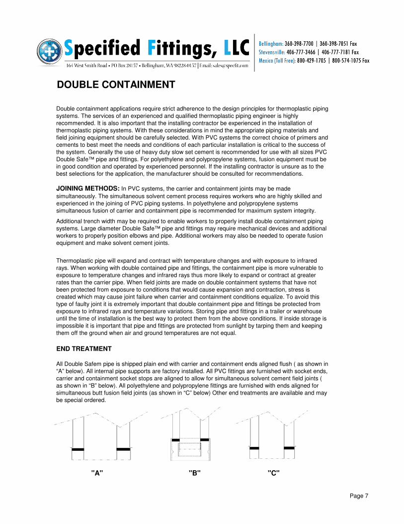
DOUBLE CONTAINMENT
END TREATMENT
"A" "B" "C"
Thermoplastic pipe will expand and contract with temperature changes and with exposure to infrared
rays. When working with double contained pipe and fittings, the containment pipe is more vulnerable to
exposure to temperature changes and infrared rays thus more likely to expand or contract at greater
rates than the carrier pipe. When field joints are made on double containment systems that have not
been protected from exposure to conditions that would cause expansion and contraction, stress is
created which may cause joint failure when carrier and containment conditions equalize. To avoid this
type of faulty joint it is extremely important that double containment pipe and fittings be protected from
exposure to infrared rays and temperature variations. Storing pipe and fittings in a trailer or warehouse
until the time of installation is the best way to protect them from the above conditions. If inside storage is
impossible it is important that pipe and fittings are protected from sunlight by tarping them and keeping
them off the ground when air and ground temperatures are not equal.
All Double Safem pipe is shipped plain end with carrier and containment ends aligned flush ( as shown in
“A” below). All internal pipe supports are factory installed. All PVC fittings are furnished with socket ends,
carrier and containment socket stops are aligned to allow for simultaneous solvent cement field joints (
as shown in “B” below). All polyethylene and polypropylene fittings are furnished with ends aligned for
simultaneous butt fusion field joints (as shown in “C” below) Other end treatments are available and may
be special ordered.
JOINING METHODS: In PVC systems, the carrier and containment joints may be made
simultaneously. The simultaneous solvent cement process requires workers who are highly skilled and
experienced in the joining of PVC piping systems. In polyethylene and polypropylene systems
simultaneous fusion of carrier and containment pipe is recommended for maximum system integrity.
Double containment applications require strict adherence to the design principles for thermoplastic piping
systems. The services of an experienced and qualified thermoplastic piping engineer is highly
recommended. It is also important that the installing contractor be experienced in the installation of
thermoplastic piping systems. With these considerations in mind the appropriate piping materials and
field joining equipment should be carefully selected. With PVC systems the correct choice of primers and
cements to best meet the needs and conditions of each particular installation is critical to the success of
the system. Generally the use of heavy duty slow set cement is recommended for use with all sizes PVC
Double Safe™ pipe and fittings. For polyethylene and polypropylene systems, fusion equipment must be
in good condition and operated by experienced personnel. If the installing contractor is unsure as to the
best selections for the application, the manufacturer should be consulted for recommendations.
Additional trench width may be required to enable workers to properly install double containment piping
systems. Large diameter Double Safe™ pipe and fittings may require mechanical devices and additional
workers to properly position elbows and pipe. Additional workers may also be needed to operate fusion
equipment and make solvent cement joints.
Page 7
Page 9
SCOPE:
MATERIALS:
MANUFACTURE:
SYSTEM DESIGN:
INSTALLATION:
TESTING: Contractor shall follow manufacturer's guidelines for system testing. A system test pressure of 50 PSI above the
normal operating pressure is recommended, in no case shall pressure exceed rating of lowest rated component
in system. Hydrostatically tested systems shall be completely bled of entrapped air through the use of relief
valves at all high points, external thrust blocks shall be installed at all capped ends and directional changes. All
containment pipe must be center loaded. Fill velocity shall not exceed 1 fps. Air pressure testing is expressly
prohibited due to the catastrophic nature of failure should failure occur.
PVC & CPVC Double Safe™
DUAL CONTAINMENT SPECIFICATIONS
System design shall be in accordance with standard industry practice for thermoplastic piping systems. System
design must take into consideration such factors as; operating and test pressures, operating and installation
temperatures, chemical and temperature de-rating factors, support spacing, anchoring, external and internal
thrust blocks, occurrence of hammer and surge pressures, chemical compatibility and exposure to infrared and
ultraviolet rays. For below ground installations design consideration must also be given to external load, load,
burial depth, ground water levels and soil conditions.
Joints shall be made with the appropriate primers and heavy duty slow set cements for solvent cement welding.
All contractor personnel involved in the making of solvent cement joints must be experienced in, and follow, the
correct procedure for solvent cement welding as described in ASTM D-2855. All factory recommendations
regarding installation, storage, handling and testing must be followed. System must be protected from exposure
to rays during installation.
This specification covers the manufacturer's requirements for Double Safe™ systems with CPVC, PVC or a
combination of CPVC and PVC piping materials.
All carrier pipe and fitting materials shall meet or exceed the requirements of ASTM D-1784 for CPVC
(chlorinated polyvinyl chloride) Type IV Grade 1 or the requirements of ASTM D-1784 for PVC (polyvinyl chloride)
Type I Grade I. Pipe and molded components must be NSF approved. All internal pipe supports shall be PVC. All
double containment pipe and fittings shall be of American make as manufactured by Specified Fittings, Inc.
All double containment fittings shall be factory preassembled. Fabricated fittings must be manufactured using a
butt fusion weld process or filet weld and fiberglass reinforced plastic reinforcement. All pipe and fittings to be
manufactured with internal pipe supports to center the carrier pipe within the annular space of the containment
pipe. No split, reworked, fillet welded or fiberglass wrapped fittings shall be used.
Page 8
Page 10
1. Always use heavy duty slow set cement designed for use with the piping materials to be joined.
3. All pipes should be clean, square cut and chamfered.
PERSONNEL REQUIREMENTS TESTING
LEAK DETECTION
TESTING
Compressed air or gases should NEVER used to test PVC systems.
6. Working quickly while all surfaces are still wet with solvent cement, insert the pipe into socket with a turn
twisting motion. The pipe must be inserted into the socket with sufficient force to insure that the pipe is inserted
the full depth of the socket. Pressure should be kept on the pipe to prevent it from backing out until both surfaces
are firmly gripped. The time will vary with diameter and installation conditions.
When installing a double wall system, two or more men may be required to apply the primer and solvent cement
and insert pipe into sockets. As pipe size in systems increase, it becomes progressively more difficult to
accomplish two solvent cement joints simultaneously, i.e., the carrier joint and containment joint. It is extremely
critical that slow set cement be used for all sizes to ensure sufficient time to make proper solvent weld joints. On
large diameter systems as many as six men may be required. For the application of primer and cement, one man
per carrier and containment male end, one man per carrier and containment socket end, and two men to insert
and hold pipe in socket while cement seats.
For large systems with many joints it is recommended that sections of the system be isolated and tested
separately.
Testing shorter sections will ensure that faulty joints can be rapidly located and repaired. Final testing of the
completed system should be performed as above when installation is complete.
When leak detection cable is used, the pull strings must be tied together as fittings are joined. Tension should be
kept on pull string so that it does not lie on bottom of pipe and bond with joint. Pull string is to be used as a guide
for heavier gauge cord, or tape used to pull leak detection cable. Leak detection cable should be pulled as pipe
and fittings are installed. Leak detection cable is not as flexible as tape or cord and care should be used when
pulling through elbows and making directional changes.
Sufficient time must be allowed for cement joints to cure. Consult tables provided by solvent cement
manufacturers for set times.
Fill carrier pipe with water. Velocity should be 1 fps or less to avoid the introduction of excessive air in system.
Pre-test system with 10 feet of head pressure. If system does not hold 10 feet of head, drain system and repair
leaks. An alternate pre-test may be made using a vacuum test method. After successful completion of pre-test,
the system may be hydrostatically pressure tested. Slowly bring system to test pressure; any build up of pressure
on a filled system suggests entrapped air in system. Release pressure and vent system again.
Containment pipe may be tested after carrier pipe has passed hydrostatic pressure test. While carrier pipe is
under pressure, a vacuum test should be made on the containment pipe.
5. Flow on a heavy coating of solvent cement while the pipe and socket surfaces are still soft and damp from
application of primer. Apply solvent cement liberally to all surfaces and fill any gaps resulting from uneven
Double Safe™ PVC & CPVC Installation Guidelines
The installation of Specified Fittings, Inc. PVC & CPVC Double Safe™ pipe and fittings should be done
exercising all the care and precautions used when installing single line systems. Due to the variety of end
treatments and fitting styles available, and differing installation requirements set forth by specifying engineers,
certain aspects of your installation may not be addressed in this overview, The following information should be
2. Use appropriately sized applicators for primer and cement. Brushes used for application of cement and primer
should be approximately ½ the size of the pipe diameter.
4. It is critical that the primer is applied in sufficient quantity to soften and penetrate the pipe. More than one
application may be required to soften the pipe. Apply primer to outer surface of pipe and inner surface of socket
until these surfaces have been penetrated and softened.
Page 9
Page 11
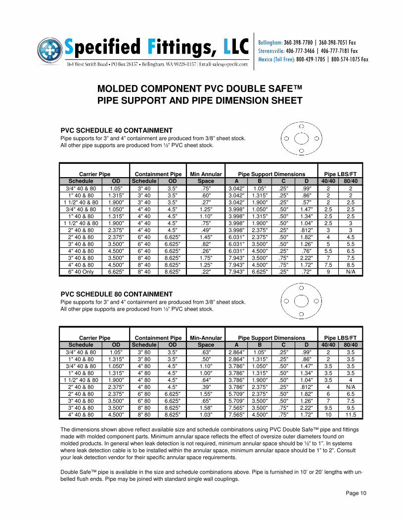
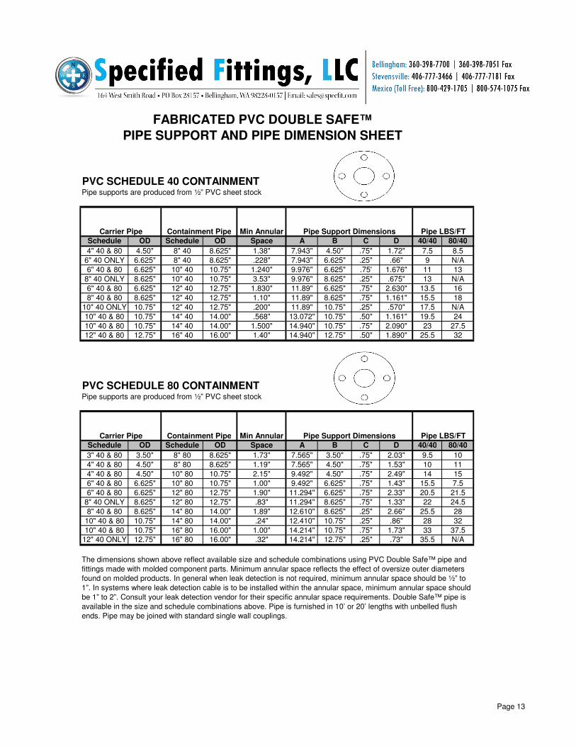
PVC SCHEDULE 40 CONTAINMENT Pipe supports for 3” and 4” containment are produced from 3/8” sheet stock.
All other pipe supports are produced from ½” PVC sheet stock.
Schedule OD Schedule OD Space A B C D 40/40 80/40
3/4" 40 & 80 1.05" 3" 40 3.5" .75" 3.042" 1.05" .25" .99" 2 2
1" 40 & 80 1.315" 3" 40 3.5" .60" 3.042" 1.315" .25" .86" 2 2
1 1/2" 40 & 80 1.900" 3" 40 3.5" .27" 3.042" 1.900" .25" .57" 2 2.5
3/4" 40 & 80 1.050" 4" 40 4.5" 1.25" 3.998" 1.050" .50" 1.47" 2.5 2.5
1" 40 & 80 1.315" 4" 40 4.5" 1.10" 3.998" 1.315" .50" 1.34" 2.5 2.5
1 1/2" 40 & 80 1.900" 4" 40 4.5" .75" 3.998" 1.900" .50" 1.04" 2.5 3
2" 40 & 80 2.375" 4" 40 4.5" .49" 3.998" 2.375" .25" .812" 3 3
2" 40 & 80 2.375" 6" 40 6.625" 1.45" 6.031" 2.375" .50" 1.82" 4 4.5
3" 40 & 80 3.500" 6" 40 6.625" .82" 6.031" 3.500" .50" 1.26" 5 5.5
4" 40 & 80 4.500" 6" 40 6.625" .26" 6.031" 4.500" .25" .76" 5.5 6.5
3" 40 & 80 3.500" 8" 40 8.625" 1.75" 7.943" 3.500" .75" 2.22" 7 7.5
4" 40 & 80 4.500" 8" 40 8.625" 1.25" 7.943" 4.500" .75" 1.72" 7.5 8.5
6" 40 Only 6.625" 8" 40 8.625" .22" 7.943" 6.625" .25" .72" 9 N/A
PVC SCHEDULE 80 CONTAINMENT Pipe supports for 3” and 4” containment are produced from 3/8” sheet stock.
All other pipe supports are produced from ½” PVC sheet stock.
Schedule OD Schedule OD Space A B C D 40/40 80/40
3/4" 40 & 80 1.05" 3" 80 3.5" .63" 2.864" 1.05" .25" .99" 2 3.5
1" 40 & 80 1.315" 3" 80 3.5" .50" 2.864" 1.315" .25" .86" 2 3.5
3/4" 40 & 80 1.050" 4" 80 4.5" 1.10" 3.786" 1.050" .50" 1.47" 3.5 3.5
1" 40 & 80 1.315" 4" 80 4.5" 1.00" 3.786" 1.315" .50" 1.34" 3.5 3.5
1 1/2" 40 & 80 1.900" 4" 80 4.5" .64" 3.786" 1.900" .50" 1.04" 3.5 4
2" 40 & 80 2.375" 4" 80 4.5" .39" 3.786" 2.375" .25" .812" 4 N/A
2" 40 & 80 2.375" 6" 80 6.625" 1.55" 5.709" 2.375" .50" 1.82" 6 6.5
3" 40 & 80 3.500" 6" 80 6.625" .65" 5.709" 3.500" .50" 1.26" 7 7.5
3" 40 & 80 3.500" 8" 80 8.625" 1.58" 7.565" 3.500" .75" 2.22" 9.5 9.5
4" 40 & 80 4.500" 8" 80 8.625" 1.03" 7.565" 4.500" .75" 1.72" 10 11.5
Double Safe™ pipe is available in the size and schedule combinations above. Pipe is furnished in 10’ or 20’ lengths with un-
belled flush ends. Pipe may be joined with standard single wall couplings.
Pipe LBS/FT
Carrier Pipe Containment Pipe Min-Annular Pipe Support Dimensions Pipe LBS/FT
Carrier Pipe Containment Pipe
The dimensions shown above reflect available size and schedule combinations using PVC Double Safe™ pipe and fittings
made with molded component parts. Minimum annular space reflects the effect of oversize outer diameters found on
molded products. In general when leak detection is not required, minimum annular space should be ½” to 1”. In systems
where leak detection cable is to be installed within the annular space, minimum annular space should be 1” to 2”. Consult
your leak detection vendor for their specific annular space requirements.
Min Annular Pipe Support Dimensions
MOLDED COMPONENT PVC DOUBLE SAFE™
PIPE SUPPORT AND PIPE DIMENSION SHEET
Page 10
Page 12
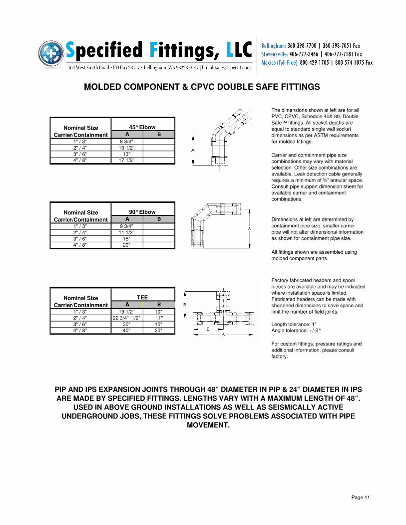
A B
1" / 3" 8 3/4"
2" / 4" 10 1/2"
3" / 6" 13"
4" / 8" 17 1/2"
A B
1" / 3" 9 3/4"
2" / 4" 11 1/2"
3" / 6" 15"
4" / 8" 20"
A B
1" / 3" 19 1/2" 10"
2" / 4" 22 3/4" 1/2" 11"
3" / 6" 30" 15" Length tolerance: 1"
4" / 8" 40" 20" Angle tolerance: +/-2°
Nominal Size
Carrier/Containment
PIP AND IPS EXPANSION JOINTS THROUGH 48” DIAMETER IN PIP & 24” DIAMETER IN IPS
ARE MADE BY SPECIFIED FITTINGS. LENGTHS VARY WITH A MAXIMUM LENGTH OF 48”.
USED IN ABOVE GROUND INSTALLATIONS AS WELL AS SEISMICALLY ACTIVE
UNDERGROUND JOBS, THESE FITTINGS SOLVE PROBLEMS ASSOCIATED WITH PIPE
MOVEMENT.
All fittings shown are assembled using
molded component parts.
For custom fittings, pressure ratings and
additional information, please consult
factory.
TEE
Factory fabricated headers and spool
pieces are available and may be indicated
where installation space is limited.
Fabricated headers can be made with
shortened dimensions to save space and
limit the number of field joints.
Nominal Size
Carrier/Containment
45° Elbow
Nominal Size
Carrier/Containment
MOLDED COMPONENT & CPVC DOUBLE SAFE FITTINGS
The dimensions shown at left are for all
PVC, CPVC, Schedule 40& 80, Double
Safe™ fittings. All socket depths are
equal to standard single wall socket
dimensions as per ASTM requirements
for molded fittings.
Carrier and containment pipe size
combinations may vary with material
selection. Other size combinations are
available. Leak detection cable generally
requires a minimum of ¾” annular space.
Consult pipe support dimension sheet for
available carrier and containment
combinations.
Dimensions at left are determined by
containment pipe size; smaller carrier
pipe will not alter dimensional information
as shown for containment pipe size.
90° Elbow
Page 11
Page 13
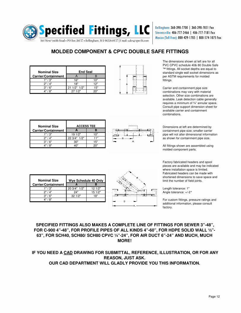
A B
1" / 3" 16" 10"
2" / 4" 18" 12"
3" / 6" 21 1/2" 1/2" 15"
4" / 8" 27 1/2" 20"
A B
1" / 3" 19 1/2" 10"
2" / 4" 22 3/4" 1/2" 11"
3" / 6" 30" 15"
4" / 8" 40" 20"
A B
1" / 3" 20 3/4" 1/2" 12 1/2" Length tolerance: 1"
2" / 4" 24" 15 1/2" Angle tolerance: +/-2°
3" / 6" 32 1/2" 18"
4" / 8"
MOLDED COMPONENT & CPVC DOUBLE SAFE FITTINGS
SPECIFIED FITTINGS ALSO MAKES A COMPLETE LINE OF FITTINGS FOR SEWER 3”-48”,
FOR C-900 4”-48”, FOR PROFILE PIPES OF ALL KINDS 4”-60”, FOR HDPE SOLID WALL ½”-
63”, FOR SCH40, SCH80/ SCH80 CPVC ¼”-24”, FOR AIR DUCT 6”-24” AND MUCH, MUCH
MORE!
IF YOU NEED A CAD DRAWING FOR SUBMITTAL, REFERENCE, ILLUSTRATION, OR FOR ANY
REASON, JUST ASK.
OUR CAD DEPARTMENT WILL GLADLY PROVIDE YOU THIS INFORMATION.
For custom fittings, pressure ratings and
additional information, please consult
factory.
All fittings shown are assembled using
molded component parts.
Factory fabricated headers and spool
pieces are available and may be indicated
where installation space is limited.
Fabricated headers can be made with
shortened dimensions to save space and
limit the number of field joints. Wye Schedule 40 Only
Nominal Size
Carrier/Containment
Nominal Size
Carrier/Containment
Nominal Size
Carrier/Containment
The dimensions shown at left are for all
PVC CPVC schedule 40& 80 Double Safe
™ fittings. All socket depths are equal to
standard single wall socket dimensions as
per ASTM requirements for molded
fittings.
Carrier and containment pipe size
combinations may vary with material
selection. Other size combinations are
available. Leak detection cable generally
requires a minimum of ¾” annular space.
Consult pipe support dimension sheet for
available carrier and containment
combinations.
Dimensions at left are determined by
containment pipe size; smaller carrier
pipe will not alter dimensional information
as shown for containment pipe size.
End Seal
ACCESS TEE
Page 12
Page 14
PVC SCHEDULE 40 CONTAINMENT Pipe supports are produced from ½” PVC sheet stock
Schedule OD Schedule OD Space A B C D 40/40 80/40
4" 40 & 80 4.50" 8" 40 8.625" 1.38" 7.943" 4.50" .75" 1.72" 7.5 8.5
6" 40 ONLY 6.625" 8" 40 8.625" .228" 7.943" 6.625" .25" .66" 9 N/A
6" 40 & 80 6.625" 10" 40 10.75" 1.240" 9.976" 6.625" .75' 1.676" 11 13
8" 40 ONLY 8.625" 10" 40 10.75" 3.53" 9.976" 8.625" .25" .675" 13 N/A
6" 40 & 80 6.625" 12" 40 12.75" 1.830" 11.89" 6.625" .75" 2.630" 13.5 16
8" 40 & 80 8.625" 12" 40 12.75" 1.10" 11.89" 8.625" .75" 1.161" 15.5 18
10" 40 ONLY 10.75" 12" 40 12.75" .200" 11.89" 10.75" .25" .570" 17.5 N/A
10" 40 & 80 10.75" 14" 40 14.00" .568" 13.072" 10.75" .50" 1.161" 19.5 24
10" 40 & 80 10.75" 14" 40 14.00" 1.500" 14.940" 10.75" .75" 2.090" 23 27.5
12" 40 & 80 12.75" 16" 40 16.00" 1.40" 14.940" 12.75" .50" 1.890" 25.5 32
PVC SCHEDULE 80 CONTAINMENT Pipe supports are produced from ½” PVC sheet stock
Schedule OD Schedule OD Space A B C D 40/40 80/40
3" 40 & 80 3.50" 8" 80 8.625" 1.73" 7.565" 3.50" .75" 2.03" 9.5 10
4" 40 & 80 4.50" 8" 80 8.625" 1.19" 7.565" 4.50" .75" 1.53" 10 11
4" 40 & 80 4.50" 10" 80 10.75" 2.15" 9.492" 4.50" .75" 2.49" 14 15
6" 40 & 80 6.625" 10" 80 10.75" 1.00" 9.492" 6.625" .75" 1.43" 15.5 7.5
6" 40 & 80 6.625" 12" 80 12.75" 1.90" 11.294" 6.625" .75" 2.33" 20.5 21.5
8" 40 ONLY 8.625" 12" 80 12.75" .83" 11.294" 8.625" .75" 1.33" 22 24.5
8" 40 & 80 8.625" 14" 80 14.00" 1.89" 12.610" 8.625" .25" 2.66" 25.5 28
10" 40 & 80 10.75" 14" 80 14.00" .24" 12.410" 10.75" .25" .86" 28 32
10" 40 & 80 10.75" 16" 80 16.00" 1.00" 14.214" 10.75" .75" 1.73" 33 37.5
12" 40 ONLY 12.75" 16" 80 16.00" .32" 14.214" 12.75" .25" .73" 35.5 N/A
Pipe LBS/FT
Carrier Pipe Containment Pipe Min Annular Pipe Support Dimensions
The dimensions shown above reflect available size and schedule combinations using PVC Double Safe™ pipe and
fittings made with molded component parts. Minimum annular space reflects the effect of oversize outer diameters
found on molded products. In general when leak detection is not required, minimum annular space should be ½” to
1”. In systems where leak detection cable is to be installed within the annular space, minimum annular space should
be 1” to 2”. Consult your leak detection vendor for their specific annular space requirements. Double Safe™ pipe is
available in the size and schedule combinations above. Pipe is furnished in 10’ or 20’ lengths with unbelled flush
ends. Pipe may be joined with standard single wall couplings.
FABRICATED PVC DOUBLE SAFE™
PIPE SUPPORT AND PIPE DIMENSION SHEET
Pipe LBS/FT
Carrier Pipe Containment Pipe Min Annular Pipe Support Dimensions
Page 13
Page 15
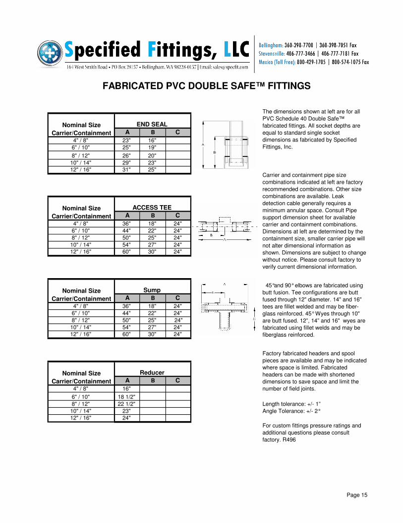
A B C
4" / 8" 11"
6" / 10" 12"
8" / 12" 13"
10" / 14" 14"
12" / 16" 15 1/2"
A B C
4" / 8" 16 1/4" 9"
6" / 10" 18" 11"
8" / 12" 19 1/2" 12"
10" / 14" 21" 12 3/4"
12" / 16" 23" 14"
A B C
4" / 8" 36" 18"
6" / 10" 44" 22"
8" / 12" 50" 25"
10" / 14" 54" 27"
12" / 16" 60" 30"
A B C
4" / 8" 41" 24 1/2" 24 1/2" Length tolerance: +/- 1”
6" / 10" 50" 31" 31" Angle Tolerance: +/- 2°
8" / 12" 60" 35" 35"
10" / 14" 64" 37" 37"
12" / 16" 68" 39" 39"
Consult Pipe support dimension sheet for
available carrier and containment
combinations. Dimensions at left are
determined by the containment size,
smaller carrier pipe will not alter
dimensional information as shown.
Dimensions are subject to change without
notice. Please consult factory to verify
current dimensional information.
45°and 90° elbows are fabricated using
butt fusion. Tee configurations are butt
fused through 12" diameter. 14" and 16"
tees are fillet welded and may be fiber-
glass reinforced. 45° Wyes through 10"
are butt fused. 12”, 14” and 16" wyes are
fabricated using fillet welds and may be
fiberglass reinforced.
Factory fabricated headers and spool
pieces are available and may be indicated
where space is limited. Fabricated
headers can be made with shortened
dimensions to save space and limit the
number of field joints.
The dimensions shown at left are for all
PVC Schedule 40 Double Safe™
fabricated fittings. All socket depths are
equal to standard single socket
dimensions as fabricated by Specified
Fittings, Inc.
Carrier and containment pipe size
combinations indicated at left are factory
recommended combinations. Other size
combinations are available. Leak
detection cable generally requires a
minimum annular space.
For custom fittings pressure ratings and
additional questions please consult
factory. R496
FABRICATED PVC DOUBLE SAFE™ FITTINGS
Nominal Size
Carrier/Containment
45° Elbow
Nominal Size
Carrier/Containment
90° Elbow
Nominal Size
Carrier/Containment
TEE
Nominal Size
Carrier/Containment
45° WYE
Page 14
Page 16
A B C
4" / 8" 23" 16"
6" / 10" 25" 19"
8" / 12" 26" 20"
10" / 14" 29" 23"
12" / 16" 31" 25"
A B C
4" / 8" 36" 18" 24"
6" / 10" 44" 22" 24"
8" / 12" 50" 25" 24"
10" / 14" 54" 27" 24"
12" / 16" 60" 30" 24"
A B C
4" / 8" 36" 18" 24"
6" / 10" 44" 22" 24"
8" / 12" 50" 25" 24"
10" / 14" 54" 27" 24"
12" / 16" 60" 30" 24"
A B C
4" / 8" 16"
6" / 10" 18 1/2"
8" / 12" 22 1/2" Length tolerance: +/- 1”
10" / 14" 23" Angle Tolerance: +/- 2°
12" / 16" 24"
The dimensions shown at left are for all
PVC Schedule 40 Double Safe™
fabricated fittings. All socket depths are
equal to standard single socket
dimensions as fabricated by Specified
Fittings, Inc.
Carrier and containment pipe size
combinations indicated at left are factory
recommended combinations. Other size
combinations are available. Leak
detection cable generally requires a
minimum annular space. Consult Pipe
support dimension sheet for available
carrier and containment combinations.
Dimensions at left are determined by the
containment size, smaller carrier pipe will
not alter dimensional information as
shown. Dimensions are subject to change
without notice. Please consult factory to
verify current dimensional information.
45°and 90° elbows are fabricated using
butt fusion. Tee configurations are butt
fused through 12" diameter. 14" and 16"
tees are fillet welded and may be fiber-
glass reinforced. 45° Wyes through 10"
are butt fused. 12”, 14” and 16" wyes are
fabricated using fillet welds and may be
fiberglass reinforced.
For custom fittings pressure ratings and
additional questions please consult
factory. R496
FABRICATED PVC DOUBLE SAFE™ FITTINGS
Nominal Size
Carrier/Containment
Sump
Nominal Size
Carrier/Containment
Reducer
Nominal Size
Carrier/Containment
END SEAL
Nominal Size
Carrier/Containment
ACCESS TEE
Factory fabricated headers and spool
pieces are available and may be indicated
where space is limited. Fabricated
headers can be made with shortened
dimensions to save space and limit the
number of field joints.
Page 15
Page 17
REMEMBER ALL TEES, CROSSES AND WYES CAN HAVE ANY OUTLET YOU
DESIRE.
THE RUN CAN BE SEWER WITH A C-900 OUTLET OR A CORRUGATED PVC RUN
WITH SDR35 OUTLETS.
THERE IS NO LIMIT TO THE PERMUTATIONS WE CAN SUPPLY!
Polyethylene or Polypropylene Line anchor joins carrier and containment pipe to limit or direct carrier line size changes due to
thermal expansion and thrust forces.
Polyethylene or Polypropylene SYSTEM RESTRAINT joins carrier and containment pipe to limit or direct carrier line size
changes due to thermal expansion and thrust forces, and serves as a system anchor when used in concrete thrust blocks.
WHEN LOOKING FOR SMALL OR LARGE AMOUNTS OF PIPE IN HDPE, PVC +
CPVC, AS WELL AS OTHER COMPOSITIONS,
PLEASE REMEMBER WE SELL PIPE!
WHETHER A TRUCKLOAD OR A SPECIFIC CUT TO LENGTH PIECE WE WILL
GLADLY LOCATE AND PRICE YOUR INQUIRY.
WE INVENTORY THE BROADEST ARRAY OF HDPE, PVC + CPVC IN NORTH
AMERICA AND WILL CUT ANY PIECE OF IT TO YOUR SPECIFICATIONS.
Double Safe™ PE and PP pipe is available in a wide variety of pipe diameters and wall size combinations. Pipe is furnished in
20' lengths with flush ends for simultaneous fusion joints or with 6" carrier extensions for staggered field joints. Some pipe
material may be subject to minimum order quantities. Consult factory for availability.
Due to the wide variety of polyethylene pipe sizes available, it is not practical to show all possible size combinations. To
calculate annular space for your carrier and containment pipe sections: Subtract the OD of the carrier pipe from the ID of the
containment pipe. Divide the result by 2. The sum is equal to the maximum annular space available for your size selection.
Molded components generally have outside diameters which are greater than the OD of pip and would decrease the annular
space. Weld beads at fusion joints will also decrease the annular space. In general, when internal leak detection is not required
minimum annular space should be 1/2 to 1 inch. In systems where leak detection cable is to be installed within the annular
space, minimum annular space should be 1 to 2 inches. Consult your leak detection vendor for specific annular space
requirements.
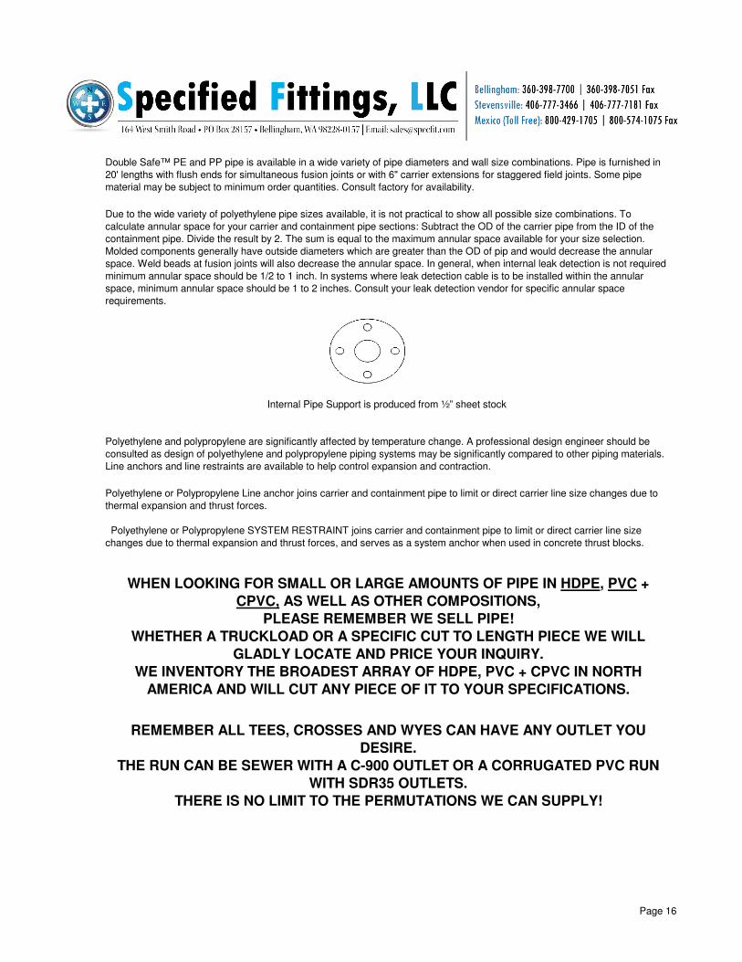
Internal Pipe Support is produced from ½” sheet stock
Polyethylene and polypropylene are significantly affected by temperature change. A professional design engineer should be
consulted as design of polyethylene and polypropylene piping systems may be significantly compared to other piping materials.
Line anchors and line restraints are available to help control expansion and contraction.
Page 16
Page 18
A B C
4" / 8" 9 1/2"
6" / 10" 10"
8" / 12" 10 1/4"
10" / 14" 10 3/4"
12" / 16" 11 3/8"
A B C
4" / 8" 14 3/4" 11 1/4"
6" / 10" 15 5/8" 12 3/8"
8" / 12" 16 5/8" 13 3/8"
10" / 14" 17 1/2" 14 1/8"
12" / 16" 18 1/2" 15 1/8"
A B C
4" / 8" 24 5/8" 12 1/4"
6" / 10" 26 3/4" 13 3/8"
8" / 12" 28 3/4" 14 3/8"
10" / 14" 30" 15"
12" / 16" 32" 16"
A B C
4" / 8" 28 1/4” 19 1/2" 19 1/2”
6" / 10" 31 1/4" 23 1/2" 23 1/2”
8" / 12" 34" 26 1/2" 26 1/2”
10" / 14" 35 3/4" 29 3/8" 29 3/8” Length tolerances: +/- 1”
12" / 16" 38 1/2" 31 1/4" 31 1/4” Angle tolerances: +/- 2°
SPECIFIED FITTINGS MAKES A COMPLETE LINE OF DRAIN BASINS AND INLINE DRAINS, 6”-48” IN
DIAMETER. WE ARE TOOLED FOR ALL BRANDS OF CORRUGATED HDPE OUTLETS, AS WELL AS
ALL SIZES OF PVC.
WE HAVE A COMPLETE LINE OF GRATES INCLUDING BUT NOT LIMITED TO ROUND, SQUARE,
HINGED, DOMED, PEDESTRIAN, SOLID, LOCKING, BRONZE AND MANY, MANY MORE!
HAVE YOU EVER FOUND YOURSELF LOOKING FOR HDPE, PVC, OR CPVC SHAPES?
WHETHER SOLID ROUND BAR, CENTERLESS GROUND BAR, SQUARE, ANGLE, HOLLOW BAR, HEX
BAR, RECTANGULAR BAR, CLEAR SOLID ROUND BAR, ETC., WE HAVE IT ALL!
WE CUSTOM CUT TO YOUR SPECIFICATIONS.
45° Elbow
Nominal Size
Carrier/Containment
90° Elbow
Nominal Size
Carrier/Containment
POLYETHYLENE FABRICATED DOUBLE SAFE™ FITTINGS
For additional Information and pressure
ratings, please consult factory.
TEE
Nominal Size
Carrier/Containment
45° WYE
Dimensions at left are determined by the
containment size; smaller carrier pipe will
not alter dimensional information as
shown. All 45° and 90° elbows are
fabricated using butt fusion. All tee and
cross configurations are butt fused
through 72” diameter. All 14" and 16" tees
will be extrusion welded and may be
fiberglass reinforced. All 45° wyes are
butt fused through 10". All 12” 14” and 16"
wyes are extrusion welded and may be
fiberglass reinforced.
Factory fabricated headers and spool
pieces are available and may be indicated
where installation space is limited.
Fabricated headers can be made with
shortened dimensions to save space and
limit the number of field joints.
The dimensions shown at left are for
Polyethylene and Polypropylene Double
Safe™ fittings with Style “C” end
treatment manufactured for simultaneous
butt fusion field joints. Other end
treatments are available.
Carrier and containment pipe size
combinations as indicated at left may vary
with material selection and containment
pipe wall thickness. Other size
combinations are available. Consult pipe
dimension sheet for available Carrier
Containment combinations.
Nominal Size
Carrier/Containment
Page 17
Page 19
A B C
4" / 8" 18" 9 1/2"
6" / 10" 18" 9 1/2"
8" / 12" 18" 9 1/2"
10" / 14" 18" 9 1/2"
12" / 16" 18" 9 1/2"
A B C
4" / 8" 22"
6" / 10" 22"
8" / 12" 22"
10" / 14" 22"
12" / 16" 22"
A B C
4" / 8" 22 5/8" 12 1/4" 24"
6" / 10" 26 3/4" 13 3/8" 24"
8" / 12" 28 3/4" 14 3/8" 24"
10" / 14" 30" 15" 24"
12" / 16" 32" 16" 24" Length tolerances: +/- .25”
Angle tolerances: +/- 2°
A B C
4" / 8" 22 5/8" 12 1/4" 24"
6" / 10" 26 3/4" 13 3/8" 24"
8" / 12" 28 3/4" 14 3/8" 24"
10" / 14" 30" 15" 24"
12" / 16" 32" 16" 24"
SPECIFIED FITTINGS BUILDS EVERY CONCEIVABLE TYPE OF TRANSITION FITTING.
FROM HDPE + PVC TO STEEL, DUCTILE IRON, COPPER, BRASS, STAINLESS, CLAY, FIBERGLASS,
CONCRETE, ALUMINUM, ETC., WE CAN DO IT ALL.
SIZE TO SIZE AND REDUCING SIZES ARE EQUALLY AVAILABLE.
WHEN LOOKING FOR SCH40 + SCH80 CLEAR PIPE AND FITTINGS PLEASE REMEMBER SPECIFIED
FITTINGS.
WE CUT PIPE TO LENGTH AND SHIP PROTECTED TO ELIMINATE DAMAGE.
CLEAR PIPE AND FITTINGS ARE AVAILABLE IN SIZES ¼”-8”.
POLYETHYLENE FABRICATED DOUBLE SAFE™ FITTINGS
The dimensions shown at left are for Polyethylene and
Polypropylene Double Safe™ fittings with Style “C” end
treatment manufactured for simultaneous butt fusion
field joints. Other end treatments are available.
Nominal Size
Carrier/Containment
REDUCER
Nominal Size
Carrier/Containment
END SEAL
Carrier and containment pipe size combinations as
indicated at left may vary with material selection and
containment pipe wall thickness. Other size
combinations are available. Consult pipe dimension
sheet for available CARRIER containment
combinations.
Dimensions at left are determined by the containment
size; smaller carrier pipe will not alter dimensional
information as shown. All 45° and 90° elbows are
fabricated using butt fusion. All tee and cross
configurations are butt fused through 72” diameter. All
14" and 16" tees will be extrusion welded and may be
fiberglass reinforced. All 45° wyes are butt fused through
10". All 12” 14” and 16" wyes are extrusion welded and
may be fiberglass reinforced.
Factory fabricated headers and spool pieces are
available and may be indicated where installation space
limited. Fabricated headers can be made with shortened
dimensions to save space and limit the number of field
joints.
For additional Information and pressure ratings, please
consult factory. Nominal Size
Carrier/Containment
SUMP ASSEMBLY
Nominal Size
Carrier/Containment
ACCESS TEE
Page 18
Page 20
Double containment applications require strict adherence to the general guidelines for butt fusion. Certain applications may
require additional steps; all procedures should be closely followed to assure a successful installation. The following may be used
as a general guideline when installing butt fused double containment piping systems. Please consult factory prior to installation to
verify that the proper fusion welding procedures are followed for your installation.
4. PLANE ENDS - Verify that ends of and containment pipe
are flush prior to planing. If ends are not flush it is an
indication of expansion of containment pipe due to excess
exposure to sunlight or infrared rays. Containment pipe
must be covered and allowed to contract to flush position
prior to planing ends or making weld. If pipe ends are flush,
planer should be used to lightly shave ends and remove
contaminants. Planed ends should be rechecked for proper
alignment.
5. MELT ENDS - Position heater between pipe ends. Bring
ends to heater at the recommended melt pressure. Allow
melt to proceed until uniform symmetrical melt beads are
formed. Drop pressure to allow heat to penetrate pipe
material and prevent dry welds.
DOUBLE CONTAINMENT BUTT FUSION GUIDELINES
6. MAKE WELD - Once melt is complete, work quickly to
separate ends to allow for removal of heater. Bring ends
together and increase pressure to recommended weld
pressure. Allow joint to cool before releasing pressure and
removing material from fusion clamps.
8. Test weld as above and check for free movement of pull
string. Continue installation carefully following fusion guidelines.
1. PIPE STORAGE - Special care should be taken to
shield double walled pipe and from exposure to direct
sunlight and infrared rays. This may be accomplished by
shielding with tarps or other materials. Failure to shield pipe
and fittings may cause expansion of the containment pipe
and result in stressed or faulty welds on carrier lines.
2. EQUIPMENT - Fusion equipment should be clean and in
good repair. Clamps will be needed for each size
containment pipe and for any single line weld to be made.
3. PREPARE PIPE - New preassembled pipe and fittings
are shipped with ends aligned and square cut. When pipe
and fittings are fixtured in clamps, ends should be
inspected to make sure that carrier and containment pipe
ends are free from dirt and foreign material. When fittings
and pipe are placed in clamps, pipe support must be
positioned under clamp surface. This step ensures proper
alignment of pipe during the fusion procedure.
7. TEST WELD - To ensure that carrier pipe has been
properly aligned and fused, it is recommended that a low
pressure (5 PSI) test be made on carrier line prior to
proceeding to next weld.
SPECIAL INSTRUCTIONS FOR SIMULTANEOUS WELDING
WITH LEAK DETECTION CABLE.
Upon request Specified Fittings, Inc. will install pull string for leak
detection cable installation. When systems are installed using a
simultaneous weld, the following steps should be added to the
double containment butt fusion guidelines.
1. A minimum of four workers is required for each welding
machine to be used. These workers will be responsible for
operation of welding machine, joining of pull string, and
tensioning pull string during weld. Certain Butt Fusion equipment
may require additional machine operators.
2. When pipe is fixtured in clamps, pull string should be at the
six o'clock position. Pull string should be positioned in such a
way that it will not be snagged by the planer, nor make contact
with heater or molten material during the melt step.
3. When melt is complete, remove heater and separate ends.
Working quickly, securely joins the ends of pull string.
4. Tension should be applied to both ends of pull string to raise
string off containment pipe and away from weld beads.
5. Bring ends to be fused together quickly and adjust machine to
weld pressure.
6. Tension should be kept on pull string until weld is complete
and weld beads are cooled.
7. Pull string may be gently pulled back and forth during weld to
prevent joining of pull string to containment pipe weld surface.
Page 19
Page 21
SCOPE:
MATERIALS:
MANUFACTURE:
SYSTEM DESIGN:
INSTALLATION:
TESTING:
POLYETHYLENE DOUBLE SAFE™ DUAL CONTAINMENT
SPECIFICATIONS
Contractor shall follow manufacturer's guidelines for system testing. A test pressure of 50 PSI above the normal operating
pressure is recommended, in no case should pressure exceed rating of lowest rated component in system. Hydrostatically
tested systems shall be completely bled of entrapped air through the use of relief valves at all high points. Thrust blocks
shall be installed at all capped ends and directional changes. All containment pipe must be center loaded. Fill velocity shall
not exceed 1 fps. Air pressure testing of carrier pipe is expressly prohibited due to the catastrophic nature of failure should
failure occur.
All dual containment pipe and fittings shall be factory assembled. Fabricated carrier fittings must be manufactured using
butt fusion. All pipe and fittings to be manufactured with internal pipe supports to center the carrier pipe within the annular
space of the containment pipe. No split, reworked, fillet or extrusion welded carrier fittings shall be used.
System design shall be in accordance with standard industry practice for thermoplastic industrial piping systems. System
design must take into consideration such factors as: operating and test pressures; operating and installation temperatures;
fluid, chemical and temperature de-rating factors; support spacing; anchoring; external and internal thrust blocks;
occurrence of water hammer and surge pressures; chemical and exposure to infrared and ultraviolet rays. For below
ground installations design consideration must also be given to external load, internal load, burial depth, ground water
levels and soil conditions.
This specification covers the manufacturer's requirements for Polyethylene Double Safe™ dual containment pipe and
fittings.
All carrier and containment piping material shall be High Density Polyethylene as per ASTM D-3350. All pipe must meet the
dimensional requirements of ASTM F-714 specifications for plastic pipe based on controlled outside diameter or, ASTM D-
2447 for plastic pipe, schedule 40 and 80, based on outside diameter. All double containment pipe and fittings shall be of
American make as manufactured by Specified Fittings, Inc., Bellingham, Washington.
Field joints shall be made using simultaneous butt fusion. All contractor personnel involved in the making of fused joints
must be experienced in, and follow, the correct procedure for butt fusion as described in ASTM D-2657. All factory
recommendations regarding installation, storage, handling, and testing must be followed. System must be protected from
exposure to infrared rays during installation.
Page 20
Page 22
WARRANTY
CAUTION
Proper installation and operating procedures should be carefully followed for all applications. Professional engineering
and design are recommended. Any questions concerning the use or installation of thermoplastic piping should be
directed to the Plastic Pipe Institute.
Your exclusive remedy for breach of contract as to any term hereof, and our only liability for any such breach shall be
replacement of such goods, or repayment to you for such goods, whichever such remedy we shall select. If we select to
repay the purchase price of any such goods and so advise you, you must return such goods to us. In no event will we be
liable for incidental or consequential damages.
Pressure ratings as stated in our literature reflect maximum recommended pressure at 73°under any operating
circumstances including test pressure, water hammer and surge pressures. All applicable derating factors must
be considered and applied for elevated temperatures, chemical compatibility, and for threaded and flanged joints.
Thermoplastic pipe and fittings include a wide variety of different plastics. Users should take special care in selecting the
type thermoplastic best suited for each installation and application. Design and selection criteria should include
chemical, temperature, velocity, pressure and installation requirements. Technical bulletins should be consulted for
suitability and also for the correct methods of installation and testing.
Specified Fittings, Inc. warrants, for a period of one year from date of shipment, that the products manufactured by
Specified Fittings, Inc. will be free from defects in materials and workmanship. If any product is found defective and
such defects are determined to be due to faulty material or workmanship, Specified Fittings, Inc. will either replace the
defective product or credit the purchase price. Specified Fittings, Inc. reserves the right to inspect such defective
products and the installation and use thereof. This warranty does not apply to products which are to have been the
subject of misuse, modification, mishandling, misapplication, improper installation, layout, thrust blocking, testing,
solvent cement joints, maintenance, repair or other negligence. Specified Fittings, Inc. makes no warranty against any
expense for removal, repair, reinstallation or any other consequential damages arising from any defect. The warranties
as stated above are the only warranties, expressed or implied, including the warranties of merchantability and fitness for
a particular purpose or application.
Special note should be made of manufacturers' recommendation AGAINST the use of compressed air in the testing of
thermoplastic pipe and fittings, and the use of thermoplastic pipe and fittings in systems which transport or store
compressed air or gasses. Pressure systems must be thrust blocked and bled of entrapped air or gasses before start up
and testing. Entrapped air or gas can cause dangerous catastrophic failure. Excessive water hammer or surge
pressures should also be avoided. To avoid the introduction of air fill velocities should not exceed one foot per second.
Page 21