1 MANUAL OF . INSTALLATION . OPERATING . MAINTENANCE DUAL FUEL GAS AND LIGHT OIL BURNERS TYPE: HP60 HP72 FOREWORD P. 2 PART I: INSTALLATION P. 4 PART II: OPERATIONS P. 18 PART III: MAINTENANCE P. 20 APPENDIX P. 26 M03957CA Rev.00 Ed.04/96 BURNERS BRULEURS BRENNER QUEMADORES BRUCIATORI
Transcript
1
MANUAL OF. INSTALLATION. OPERATING. MAINTENANCE
DUAL FUELGAS AND LIGHT OILBURNERS TYPE:
HP60HP72
FOREWORD P. 2
PART I: INSTALLATION P. 4
PART II: OPERATIONS P. 18
PART III: MAINTENANCE P. 20
APPENDIX P. 26
M03957CA Rev.00 Ed.04/96
B U R N E R SB R U L E U R SB R E N N E RQUEMADORESB R U C I AT O R I
2
GENERAL INTRODUCTION
* This instruction sheet is supplied as an integral and essential part of theproduct and must be delivered to the user.Carefully read these instructions, as they supply important information oninstallation, use, safety and maintenance.The equipment must be installed in compliance with the regulations in force,following the manufacturer’s instructions, by qualified personnel.Qualified personnel means those having technical knowledge in the field ofcomponents for civil heating systems and sanitary hot water generationand, in particular, service centres authorised by the manufacturer.Improper installation may cause injury to people and animals, or damage toproperty, for which the manufacturer cannot be held liable.
* Remove all packaging material and inspect the equipment for integrity.In case of any doubt, do not use the unit - contact the supplier.The packaging materials (wooden crate, nails, fastening devices, plasticbags, foamed polystyrene, etc), should not be left within the reach of children,as they may prove harmful.
* Before any cleaning or servicing operation, disconnect the unit from themains by turning the master switch OFF, and/or through the cut-out devicesthat are provided.
* Make sure that inlet or exhaust grilles are unobstructed.
* In case of breakdown and/or defective unit operation, disconnect the unit.Make no attempt to repair the unit or take any direct action. Contact qualifiedpersonnel only.Units shall be repaired exclusively by a servicing centre, duly authorised bythe manufactureer, with original spare parts.Failure to comply with the above instructions is likely to impair the unit’ssafety.To ensure equipment efficiency and proper operation, it is essential thatmaintenance operations are performed by qualified personnel at regularintervals, following the manufacturer’s instructions.
* When a decision is made to discontinue the use of the equipment, thoseparts likely to constitute sources of danger shall be made harmless.
* In case the equipment is to be sold or transferred to another user, or incase the original user should move and leave the unit behind, make surethat these instructions accompany the equipment at all times,so that theycan be consulted by the new owner and/or the installer.
* For all the units that have been modified or have options fitted then originalaccessory equipment only shall be used.
* This unit shall be employed exclusively for the use for which it is meant.Any other use shall be considered as improper and, therefore, dangerous.The manufacturer shall not be held liable, by agreement or otherwise, fordamages resulting from improper installation and use, and failure to complywith the instructions supplied by the manufacturer.
2. SPECIAL INSTRUCTIONS FOR BURNERS
*The burner should be installed in a suitable room, with ventilation openingscomplying with the requirements of the regulations in force, and sufficientfor good combustion.
* Only burners designed according to the regulations in force should beused.
* This burner should be employed exclusively for the use for which it wasdesigned.
* Before connecting the burner, make sure that the unit rating is the same asdelivery mains (electricity, gas gasoil, or other fuel).
*Observe caution with hot burner components. These, are usually near tothe flame and the fuel pre-heating system, if any become hot during the unitoperation they will remain hot for some time after the burner has stopped.
* When the decision is made to discontinue the use of the burner, the usershall have qualified personnel carry out the following operations:
a) remove the power supply by disconnecting the power cable fromthe master
b) disconnect the fuel supply by means of the hand-operated shut-offvalve and remove the control handwheels from their spindles.
SPECIAL WARNINGS
* Make sure that the burner has, on installation, been firmly secured to theappliance, so that the flame is generated inside the appliance firebox.
* Before the burner is started and, thereafter, at least once a year, havequalified personnel perform the following operations:
a) Set the burner fuel flow rate depending on the heat input of theappliance.
b) Set the flow rate of the combustion-supporting air to obtain acombustion efficiency level at least equal to the lower level requiredby the regulations in force.
c) Check the unit operation for proper combustion, to avoid any harmfulor polluting unburnt gases in excess of the limits permitted by theregulations in force.
d) Make sure that control and safety devices are operating properly.
e) Make sure that exhaust ducts intended to discharge the products ofcombustion are operating properly.
f) On completion of setting and adjustment operations, make sure thatall mechanical locking devices of controls have been duly tightened.
g) Make sure that a copy of the burner use and maintenance instructionsis available in the boiler room.
* In case of repeated burner shut-downs, do not continue re-setting the unitmanually. Contact qualified personnel to take care of such defects.
* The unit shall be operated and serviced by qualified personnel only, incompliance with the regulations in force.
3. GENERAL INSTRUCTIONS DEPENDING ON FUEL USED
3A ELECTRICAL CONNECTION
* For safety reasons the unit must be efficiently earthed and installed asrequired by current safety regulations.
* It is vital that all saftey requirements are met. In case of any doubt, ask foran accurate inspection of electrics by qualified personnel, since themanufacturer cannot be held liable for damages that may be caused byfailure to correctly earth the equipment.
* Qualified personnel must inspect the system to make sure that it is adequate
PREFACES
NOTICES
- THIS MANUAL IS SUPPLIED AS AN INTEGRAL AND ESSENTIAL PART OF THE PRODUCT AND MUST BEDELIVERED TO THE USER.
- INFORMATION INCLUDED IN THIS SECTION ARE DEDICATED BOTH TO THE USER AND TO PERSONNELFOLLOWING PRODUCT INSTALLATION AND MAINTENANCE.
- CAREFULLY KEEP THIS MANUAL FOR FUTURE REFERENCE.
3
to take the maximum power used by the equipment shown on the equipmentrating plate. In particular, make sure that the system cable cross section isadequate for the power absorbed by the unit.
* No adaptors, multiple outlet sockets and/or extension cables are permittedto connect the unit to the electric mains.An omnipolar switch shall be provided for connection to mains, as requiredby the current safety regulations.
The use of any power-operated component implies observance of a fewbasic rules, for example:
- do not touch the unit with wet or damp parts of the body and/or withbare feet;
- do not pull electric cables;- do not leave the equipment exposed to weather (rain, sun, etc.)
unless expressly required to do so;- do not allow children or inexperienced persons to use equipment;
* The unit input cable shall not be replaced by the user.In case of damage to the cable, switch off the unit and contact qualifiedpersonnel to replace.
* When the unit is out of use for some time the electric switch supplying allthe power-driven components in the system (i.e. pumps, burner, etc.) shouldbe switched off./cont’ d...
3B FIRING WITH GAS, GASOIL OR OTHER FUELS
GENERAL
* The burner shall be installed by qualified personnel and in compiance withregulations and provisions in force; wrong installation can cause injuries topeople and animals, or damage to property, for which the manufacturer cannotbe held liable.
* Before installation, it is recommended that all the fuel supply system pipesbe carefully cleaned inside, to remove foreign matter that might impair theburner operation.
* Before the burner is commissioned, qualified personnel should inspect thefollowing:
a) the fuel supply system, for proper sealing and pressure soundness;b) the fuel flow rate, to make sure that it has been set based on the
firing rate required of the burner;c) the burner firing system, to make sure that it is supplied for the
designed fuel type;d) the fuel supply pressure, to make sure that it is included in the range
shown on the rating plate;e) the fuel supply system, to make sure that the system dimensions
are adequate to the burner firing rate, and that the system isequippped with all the safety and control devices required by theregulations in force.
* When the burner is to remain idle for some time, the fuel supply tap or tapsshould be closed.
SPECIAL INSTRUCTIONS FOR USING GAS
* Have qualified personnel inspect the installation to ensure that:a) the gas delivery line and train are in compliance with the regulations
and provisions in force;
b) all gas connections are tight;
c) the boiler room ventilation openings are such that they ensure theair supply flow required by the currrent regulations, and in any caseare sufficient for proper combustion.
* Do not use gas pipes to earth electrical equipment.
* Never leave the burner connected when not in use. Always close the gasvalve.
* In case of prolonged absence of the user, the main gas delivery valve tothe burner should be closed.
PREFACES
Precautions if you can smell gas:
a) do not operate electric switches, the telephone, or any other itemlikely to generate sparks;
b) immediately open doors and windows to create an air flow to purgethe room;
c) close the gas valves;
d) contact qualified personnel.
* Do not obstruct the ventilation openings of the room where gas appliancesare installed, to avoid dangerous conditions such as the development oftoxic or explosive mixtures.
Fuel Natural Gas - Light Oil Natural Gas - Light OilCategory I2ELL I2ELL
Max. oil viscosity (°E a 20°C) 1.8 1.8Gas flow rate (min-max) (St m3/h) 18 - 93.1 34.9 - 164Light oil flow rate (min-max)kg/h 21 - 74 34.5 - 130.5Electric supply 230/400 V - 50 Hz 230/400 V - 50 HzElectric comsuption kW 2.15 3.25Fan motor kW 1.1 2.2Amperes (230/400) A 5 - 2.9 8.1 - 4.7Pump motor kW 0.55 0.55
6
FIR
ING
RE
SIS
TA
NC
E I
N C
.D.C
. m
bar
FIR
ING
RE
SIS
TA
NC
E I
N C
.D.C
. m
bar
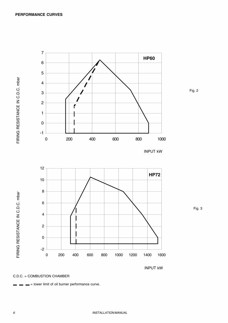
PERFORMANCE CURVES
INSTALLATION MANUAL
C.D.C. = COMBUSTION CHAMBER
= lower limit of oil burner performance curve.
Fig. 2
Fig. 3
-1
0
1
2
3
4
5
6
7
0 200 400 600 800 1000
-2
0
2
4
6
8
10
12
0 200 400 600 800 1000 1200 1400 1600
HP60
HP72
INPUT kW
INPUT kW
7
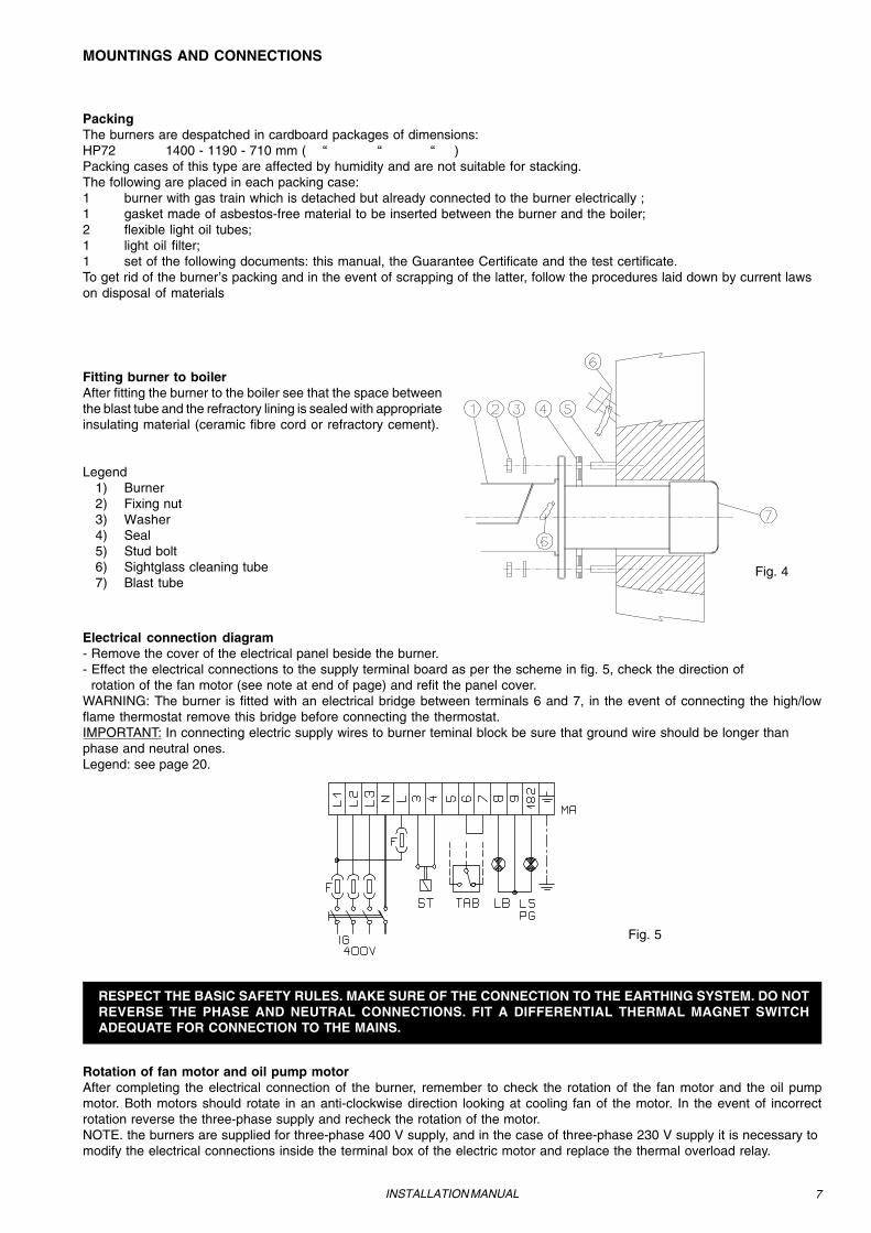
RESPECT THE BASIC SAFETY RULES. MAKE SURE OF THE CONNECTION TO THE EARTHING SYSTEM. DO NOTREVERSE THE PHASE AND NEUTRAL CONNECTIONS. FIT A DIFFERENTIAL THERMAL MAGNET SWITCHADEQUATE FOR CONNECTION TO THE MAINS.
MOUNTINGS AND CONNECTIONS
Rotation of fan motor and oil pump motorAfter completing the electrical connection of the burner, remember to check the rotation of the fan motor and the oil pumpmotor. Both motors should rotate in an anti-clockwise direction looking at cooling fan of the motor. In the event of incorrectrotation reverse the three-phase supply and recheck the rotation of the motor.NOTE. the burners are supplied for three-phase 400 V supply, and in the case of three-phase 230 V supply it is necessary tomodify the electrical connections inside the terminal box of the electric motor and replace the thermal overload relay.
PackingThe burners are despatched in cardboard packages of dimensions:HP72 1400 - 1190 - 710 mm ( “ “ “ )Packing cases of this type are affected by humidity and are not suitable for stacking.The following are placed in each packing case:1 burner with gas train which is detached but already connected to the burner electrically ;1 gasket made of asbestos-free material to be inserted between the burner and the boiler;2 flexible light oil tubes;1 light oil filter;1 set of the following documents: this manual, the Guarantee Certificate and the test certificate.To get rid of the burner’s packing and in the event of scrapping of the latter, follow the procedures laid down by current lawson disposal of materials
Fitting burner to boilerAfter fitting the burner to the boiler see that the space betweenthe blast tube and the refractory lining is sealed with appropriateinsulating material (ceramic fibre cord or refractory cement).
Electrical connection diagram- Remove the cover of the electrical panel beside the burner.- Effect the electrical connections to the supply terminal board as per the scheme in fig. 5, check the direction of rotation of the fan motor (see note at end of page) and refit the panel cover.WARNING: The burner is fitted with an electrical bridge between terminals 6 and 7, in the event of connecting the high/lowflame thermostat remove this bridge before connecting the thermostat.IMPORTANT: In connecting electric supply wires to burner teminal block be sure that ground wire should be longer thanphase and neutral ones.Legend: see page 20.
Fig. 5
8 INSTALLATION MANUAL
Gas train installation diagramsIn fig. 6 they are shown all the components of the gas train included in the supply and those which must be fitted by theinstaller. The scheme shown satisfy the current provisions of the law .
1 2 43 5
LEGEND1) Burner2) Gas twin valve (including gas
pressure switch)3) Leak detection monitor (Optional on
type HP60)4) Gas governor and filter5) Manually Operated Shutt-off Valve
Size: see technical data - gasconnection
SUPPLIER INSTALLER
Fig. 6
SPECIAL REQUIREMENTS FOR APPLICATIONS ON STEAM BOILERS
Burners installed on steam boilers must comply with TRD regulations, they shall always be equipped with:- leak detection monitor,- continuous service burner control box,- maximum gas pressure switch.When ordering the burner remember to specify if such equipment is required.
Light Oil tubing installation diagram
Key: 1) Burner 2) Flexible tubing (kit) 3) Gas filter (kit) 4) Automatic interceptor (*) 5) One-way valve (*) 6) Gate valve FROM TANK 7) Quick-closing gate-valve (not in vicinity of tank or boiler) TO TANK
(*) Only for installations with gravity, siphonor forced circulation feed systems.
Examples of light oil feed systems
Gravity feed system
Key:1) Manual interceptor valve2) Gas filter3) Light Oil feed pump4) One way valve5) Light Oil flexible tubing6) Spillage valve
1 2 3 4
1 2 5
4 5
Fig. 7
Fig. 8
9INSTALLATION MANUAL
1 2 3 1 2 5
6 4 5
1 2 5
5
4
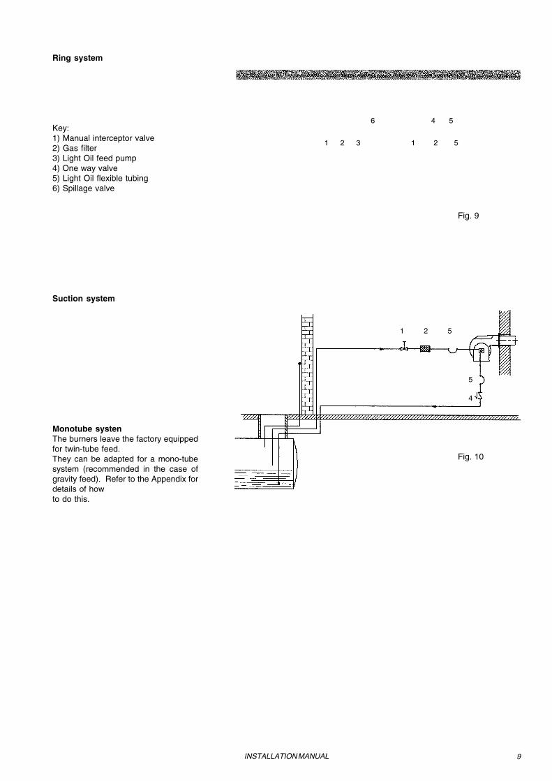
Ring system
Key:1) Manual interceptor valve2) Gas filter3) Light Oil feed pump4) One way valve5) Light Oil flexible tubing6) Spillage valve
Suction system
Monotube systenThe burners leave the factory equippedfor twin-tube feed.They can be adapted for a mono-tubesystem (recommended in the case ofgravity feed). Refer to the Appendix fordetails of howto do this.
Fig. 9
Fig. 10
10 INSTALLATION MANUAL
Fig. 12
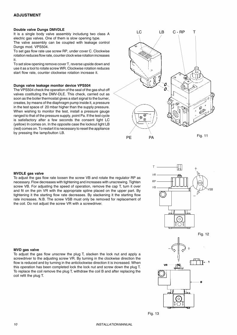
LC LB C - RP TDouble valve Dungs DMVDLEIt is a single body valve assembly includung two class Aelectric gas valves. One of them is slow opening type.The valve assembly can be coupled with leakage controlDungs mod. VPS504.To set gas flow rate use screw RP, under cover C. Clockwiserotation reduces flow rate, counter clock wise rotation increasesit.To set slow opening remove cover T, reverse upside down anduse it as a tool to rotate screw WR. Clockwise rotation reducesstart flow rate, counter clockwise rotation increase it.
Dungs valve leakage monitor device VPS504The VPS504 check the operation of the seal of the gas shut offvalves costituting the DMV-DLE. This check, carried out assoon as the boiler thermostat gives a start signal to the burner,creates, by means of the diaphragm pump inside it, a pressurein the test space of 20 mbar higher than the supply pressure.When wishing to monitor the test, install a pressure gaugeranged to that of the pressure supply, point Pa. If the test cycleis satisfactory after a few seconds the consent light LC(yellow) In comes on. In the opposite case the lockout light LB(red) comes on. To restart it is necessary to reset the applianceby pressing the lamp/button LB.
ADJUSTMENT
MVDLE gas valveTo adjust the gas flow rate loosen the screw VB and rotate the regulator RP asnecessary. Flow decreases with tightening and increases with unscrewing. Tightenscrew VB. For adjusting the speed of operation, remove the cap T, turn it overand fit on the pin VR with the appropriate spline placed on the upper part. Bytightening it the starting flow rate decreases. By slackening it the starting flowrate increases. N.B. The screw VSB must only be removed for replacement ofthe coil. Do not adjust the screw VR with a screwdriver.
MVD gas valveTo adjust the gas flow unscrew the plug T, slacken the lock nut and apply ascrewdriver to the adjusting screw VR. By turning in the clockwise direction theflow is reduced and by turning in the anticlockwise direction it is increased. Whenthis operation has been completed lock the lock nut and screw down the plug T.To replace the coil remove the plug T, withdraw the coil B and after replacing thecoil refit the plug T.
PE PA Fig. 11
Fig. 13
11INSTALLATION MANUAL
LANDIS gas valveVersion with SPK10: no adjustment necessary.- Important: Do not remove the cover as oil may leak out.Version with SKP20: (with built in pressure stabiliser).- To increase or decrease gas pressure, and therefore gas flow, remove the capand use a screwdriver to adjust the regulator screw VR. Turn clockwise to increasethe flow, anti-clockwise to reduce it.- Connect up the gas tubing to the gas pressure nipple (TP in Fig.14).- Leave the breather free (SA in Fig.14).- Should the spring that is fitted not permit satisfactory regulation, ask one of ourservice centres for a suitable replacement.
VR
SATP
Fig. 14
Leak Detection KROM SCHRODER TC218This device checks the closure of the gas valves by acting directly on themaccording to a sequence controlled by an electronic programme. The deviceincludes light signals (LEDs) to indicate the phase of the cycle of operation andwhich solenoid valve is leaking. If a momentary loss of voltage occurs during thetest the system automatically starts up again. If that happens during a test failureboth LEDs light up.
Legend of Light SignalsA - Test in progressB - Regular operationC - Loss of upstream solenoid valve (EV1)D - Loss of downstream solenoid valve (EV2)PS - reset Button Fig. 15
TR
Fig. 16
Pressure GovernorTo increase the gas pressure on outlet, adjust with a screwdriver screw TR asindicated in figure 16.
12 INSTALLATION MANUAL
1
2 3 3
56
7
833
4
1
2 3 3
4
56
7833
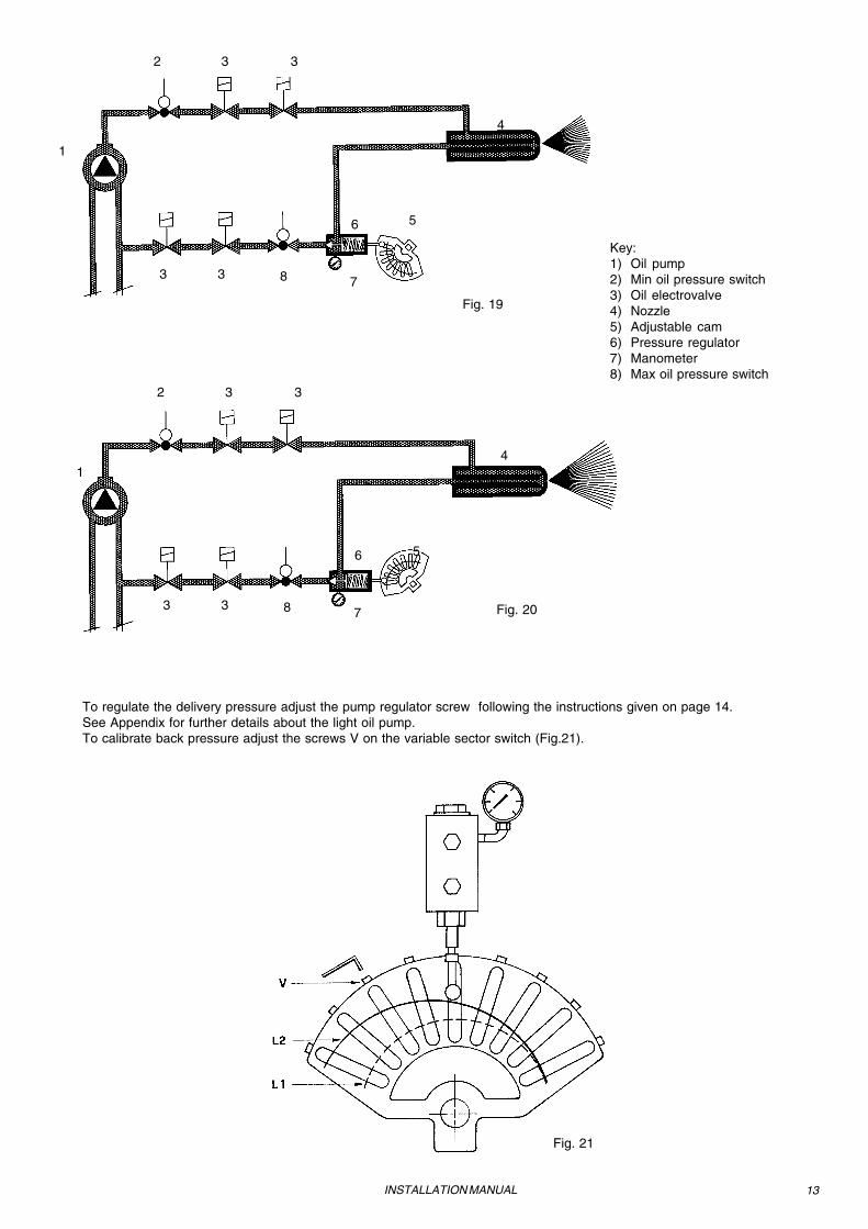
Key:1) Oil pump2) Min oil pressure switch3) Oil electrovalve4) Nozzle5) Adjustable cam6) Pressure regulator7) Manometer8) Max oil pressure switch
To prime the pumpBefore starting to regulate for light oil operation it is necessary to prime the light oil pump using the following procedure:- turn on the burner; when the electrovalve comes on switch on the light resistor and clear the air out of the manometer
connection. Before starting up the burner make sure that the tube leading back to the tank is not obstructed. Any blockagecould lead to failuer of the pump seal.
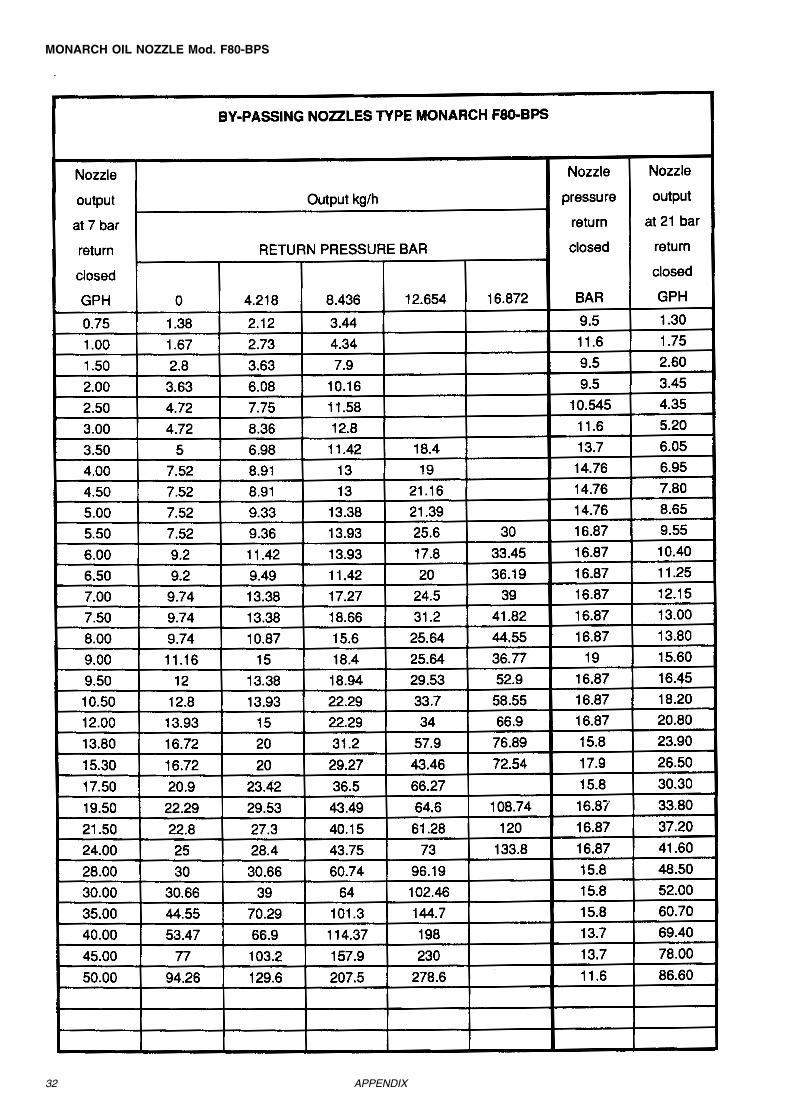
To regulate the light oil flowTo adjust the light oil flow select a nozzle (reflux type) of approapriate size and calibrate the delivery and return pressure usingthe information in Tab.1(see Fig.17 for an outline diagram of the light oil circuit); for correct nozzle size refer to the tables in theAppendix.
* Fo r the flow a t d iffe ren t p res s ure leve ls s ee the tab les in Appendix.
Fig. 17
Fig. 18
13
Fig. 19
Fig. 21
To regulate the delivery pressure adjust the pump regulator screw following the instructions given on page 14.See Appendix for further details about the light oil pump.To calibrate back pressure adjust the screws V on the variable sector switch (Fig.21).
INSTALLATION MANUAL
1
2 3 3
4
56
7833
2 3 3
4
56
7833
1
Key:1) Oil pump2) Min oil pressure switch3) Oil electrovalve4) Nozzle5) Adjustable cam6) Pressure regulator7) Manometer8) Max oil pressure switch
Fig. 20
14
Fig. 22
Fig. 23
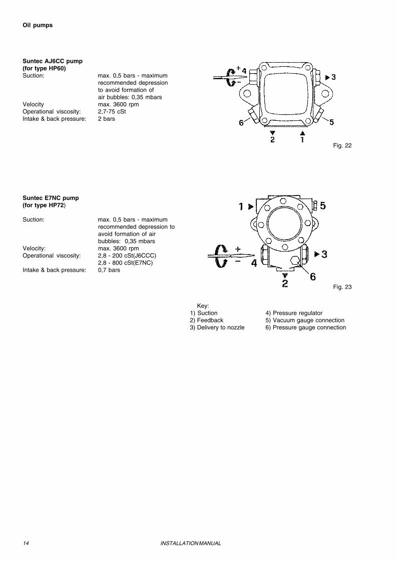
Oil pumps
Suntec AJ6CC pump(for type HP60)Suction: max. 0,5 bars - maximum
NOTA BENE: During commissioning operations, do not let the burner function with insufficient air flow (danger of formation ofcarbon monoxide); if this should happen, shut down the burner, increase the opening of the air damper and start up the burneragain to ensure the purging of the carbon monoxide from the combustion chamber.
Fig. 26
V VRA
VRA
RA
- During testing in the facory the gas butterfly valve, air damper and oilnozzle pressure at low flame and the servo-control cams set accordingly.
- To recalibrate the burner at the time of on-site testing, employ thefollowing procedure.
1. Light the gas burner and keep the servo-control in the ignition position byusing the AUTO-MAN on the servo-control switch (ignition position = 0°).
2. To regulate the ignition air flow move the servo-control cam AB (seefig.24) (to increase air flow increase servo- control position angle). Toregulate the ignition gas flow turn the adjustable screws V (see fig. 26) tochange the opening of the butterfly valve (see Fig.25). Turn clockwise toincrease the gas flow and anti-clockwise to reduce it.
3. Switch off the burner, put the AUTO-MAN servo-control switch in AUTOposition and start the burner again. If the setting is correct proceed to point4, on the contrary correct it again.
4. With the servo-control switch in MAN position turn the servocontrol up tohigh flame (servo-control position = 90°).IMPORTANT NOTICE: move the servocontrol by hand slowly, takingcare to combustion values in order to be sure not to let the burner functionwith insufficient air flow. Regulate the gas flow to the required figure byadjusting the pressure stabilizer or the regulator valve (see page 10). Toadjust the air flow rate slacken the screw RA and rotate the screw VRA(CW rotation increases air flow, while CCW rotation decreases it) until thedesired flow rate is obtained. (fig. 26).
5. Turn the burner down to low flame, to regulate the gas flow act on theadjustable screws V as described at point 2.
6. Should it be necessary to adjust burner capacity at low flame move theservocontrol cam BF accordingly (see Fig.24). The low-flame positionshould never coincide with the ignition position, so for this reason thecam has be calibrated at least 5° off the ignition position.
7. Put the AUTO-MAN servo-control switch in AUTO position and checkburner starting again, if gas or air flow need further adjustment proceedas described at point 2.
8 Light the oil burner. Should it be necessary to adjust the oil ignition flowmove the adjustable screws as shown in fig. 21.
9 With the servo-control switch in MAN position , turn the servocontrol upto high flame following the same precautioni described at point 4. Turnthe servocontrol switch to “AUTO” position and regulate the oil flow bymeans of “V” screws, see fig. 21.
10 Turn the burner down to low flame, check combustion, if necessaryregulate the oil flow by adjusting the screws “V” (see fig. 21).
N.B. On final adjustment, make sure the locking screw RA is fully tightened.
BF AB Fig.24
Fig. 25
16 INSTALLATION MANUAL
Calibration of air pressure switchCalibration is carried out as follows:Remove the transparent plastic cap.After air and gas setting has been completed , start the burner and,while prepurge phase is running, slowly turn the adjusting ring nut VRin the clockwise direction until the burner lockout (on the Elbi pressureswitch undo screw VB).Read the value on the pressure switch scale and reduce it by 15%.Repeat the ignition cycle of the burner and check it runs properly.Refit the cover on the pressure switch (on Elbi pressure switchremember to tighten screw VB).
Fig. 27
Calibration of minimum gas pressure switchThe minimum gas pressure switch is fitted to the multibloc valve unit.Calibrations is carried out as follows:Remove the transparent plastic cover .With the burner in operation measure the pressure on the pressure porton pressure switch and close the shut off valve (n° 4 in installationdiagram) slowly until the detected pressure is reduced by 50%.Verify CO emissions of the burner, if the measured value is smaller than80 ppm screw down the adjusting ring nut until the burner is turned off(on the Elbi pressure siwtch undo screw VB.If CO emissions are greater than 80 ppm slightly open the shut off valveuntil the CO value is reduced below 80 ppm, then screw down theadjusting ring nut until the burner is turned off.Fully open the valve n° 4.Refit the cover on the pressure switch (on Elbi pressure switchremember to tighten screw VB).
Calibrating the high gas pressure switchThe high gas pressure switch is fitted on the burner close to the butterflyvalve and is connected by copper tube. For calibration proceed as follows:Remove the transparent plastic coverBring the burner to maximum outputRotate the adjustment ring nut VR clockwise, until the burner stops(on the Elbi pressure siwtch undo screw VB).Rotate the adjustment ring nut slightly back (increase the valueindicated on the scale nut after rotation by 30 % ).In the event of stoppage rotate the adjustment ring nut slightly furtherback.Refit the cover (on Elbi pressure switch remember to tighten screwVB)
Fig. 28
17INSTALLATION MANUAL
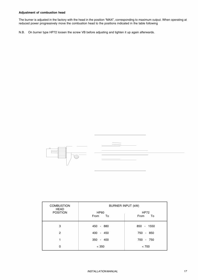
Adjustment of combustion head
The burner is adjusted in the factory with the head in the position “MAX”, corresponding to maximum output. When operating atreduced power progressively move the combustion head to the positions indicated in the table following
N.B. On burner type HP72 loosen the screw VB before adjusting and tighten it up again afterwards.
COMBUSTION BURNER INPUT (kW)HEAD
POSITION HP60 HP72From To From To
3 450 - 880 850 - 1550
2 400 - 450 750 - 850
1 350 - 400 700 - 750
0 < 350 < 700
18
PART II: OPERATIONS MANUAL
OPERATIONS MANUAL
LIMITATIONS OF USETHE BURNER IS AN APPLIANCE DESIGNED AND CONSTRUCTED TO OPERATE ONLY AFTER BEINGCORRECTLY CONNECTED TO A HEAT GENERATOR (E.G. BOILER, HOT AIR GENERATOR, FURNACE,ETC.), ANY OTHER USE IS TO BE CONSIDERED IMPROPER AND THEREFORE DANGEROUS.
THE USER MUST GUARANTEE THE CORRECT FITTING OF THE APPLIANCE, ENTRUSTING THEINSTALLATION OF IT TO QUALIFIED PERSONNEL AND HAVING THE FIRST COMMISSIONING OF ITCARRIED OUT BY A SERVICE CENTRE AUTHORISED BY THE COMPANY MANUFACTURING THEBURNER. A FUNDAMENTAL FACTOR IN THIS RESPECT IS THE ELECTRICAL CONNECTION TO THEGENERATOR’S CONTROL AND SAFETY UNITS (CONTROL THERMOSTAT, SAFETY, ETC.) WHICHGUARANTEES CORRECT AND SAFE FUNCTIONING OF THE BURNER.
THEREFORE ANY OPERATION OF THE APPLIANCE MUST BE PREVENTED WHICH DEPARTS FROM THEINSTALLATION OPERATIONS OR WHICH HAPPENS AFTER TOTAL OR PARTIAL TAMPERING WITH THESE(E.G. DISCONNECTION, EVEN PARTIAL, OF THE ELECTRICAL LEADS, OPENING THE GENERATOR DOOR,DISMANTLING OF PART OF THE BURNER).
DO NOT EVER OPEN OR DISMANTLE ANY COMPONENT OF THE MACHINE.
OPERATE ONLY THE MAIN SWITCH (“ON-OFF” SEE FIG. 31), WHICH THROUGH ITS EASY ACCESSIBILITYAND RAPIDITY OF OPERATION ALSO FUNCTIONS AS AN EMERGENCY SWITCH, AND ON THE RE-SETBUTTON.
IN THE EVENT OF REPEATED LOCKOUTS, DO NOT PERSIST WITH THE RE-SET BUTTON AND CONTACTQUALIFIED PERSONNEL WHO WILL PROCEED TO ELIMINATE THE MALFUNCTION.
WARNING: DURING NORMAL OPERATION THE PARTS OF THE BURNER NEAREST TO THE GENERATOR(COUPLING FLANGE) CAN BECOME VERY HOT, AVOID TOUCHING THEM SO AS NOT TO GET BURNT.
OPERATION
- Select the fuel by turning the switch A on the burner control panel.N.B. where light oil is used make sure than the interceptor valves on the feed and return tubes are turned on.
- Check that the mechanism is not blocked (LED B lights up), if it is reactivate it by pressing the reset button C.- Check that the series of thermostats (or pressostats) gives the all clear for operating the burner.
Gas Operation- Check that the gas feed pressure is high enough (LED D will come on).- Start the checking cycle for the gas-tight monitor of the gas valves. When the check is completed the gas-tight monitor LED
will light up on the control panel. When the gas valve check is completed the burner start-up cycle begins.- At the beginning of the start-up cycle the servo control operates the air damper to maximum opening and the fan motor
starts and the pre-purge phase begins. During the pre-purge phase the complete opening of the air damper is signalled bythe lighting of the indicator light F on the front panel.
- At the end of the pre-purge the air damper is brought to the ignition position, the ignition transformer is energised (signalledby indicator light H on the panel) and, after 3 sec., the two gas valves EV1 and EV2 are energised (indicator lights I and Lon the mimic panel). 3 seconds after the opening of the gas valves the ignition transformer is de-energised and the light His extinguished.
- The burner is firing in low flame (indicator light G lit up); after 14 sec. 2-stage operation initiates and the burner is broughtautomatically into high flame, or remains in low flame according to the requirements of the plant. Operation in high or lowflame is signalled by the lighting up/extinguishing of the indicator light F on the mimic panel.
Light Oil operation- The ventilation motor comes on and the pre-ventilation phase begins. Since the pre-soak cycle must be carried out with
maximum air flow the monitor only switches on the servo-control once the damper is fully open which in turn signals the startof the pre-ventilation time period lasting 36 seconds.
- At the end of the pre-ventilation period the servo-control moves to the light oil ignition position, and as soon as is reaches thisposition the ignition transformer comes on (indicated by LED I on the display panel). Two seconds after the light oil valve opensthe ignition transformer is cut out of the circuit and LED I goes out.
- This lights the burner, and at the same time the servo control moves to the high-flame position, and after 14 seconds it movesinto 2 stage mode and the burner either turns up automatically to high flame or remains on low flame as the system demands.High or low flame operation is indicated by whether the LED G on the display panel is on (high) or off (low).
19OPERATIONS MANUAL
Key:A: Main on/off switchB: LED indicating burner blockedC: Re-set button for burner monitorD: LED indicating gas pressostat all-clearE: LED indicating valve gas-tight monitor blockedF: Reset button for valve gas-tight monitor (only for burners fitted with LANDIS LDU11 monitor.G: LED indicating high-flame operationH: LED indicating low-flame operationI: LED indicating ignition tramnsformer workingL: LED indicating thermal relay onM: LED indicating gas valve EV1 onN: LED indicating gas valve EV2 onO: LED indicating Stand-by mode.P: LED indicating light oil valves onQ: Automatic-manual control of burner CAPACITY (only on fully modulating models)R: LANDIS RWF32.00 (only on fully modulating models).
Fig. 31
Front panel
G H IL
B
O
PDNM
E
C F
A Q
R
20
PART III: MAINTENANCE MANUAL
MAINTENANCE MANUAL
At least once a year carry out the maintenance operations listed below. In the case of seasonal servicing, it is recommended tocarry out the maintenance at the end of each heating season; in the case of continuous operation the maintenance is carried outevery 6 months.
N.B. All operations on the burner must be carried out with the power disconnected
PERIODICAL SERVICING- Clean and examine the gas filter cartridge and replace if necesssary;- Clean and examine the light oil filter cartridge and replace if necessary;- Examine the condition of the light oil flexible tubing and check for possible leaks.- Clean and examine the filter inside the light oil pump (see instructions in the Appendix).- Dismantle and clean the combustion head (see Fig.45-6).- Examine and clean the ignition electrodes, adjust and replace if necessary (see Fig.47).- Dismantle and clean the light oil nozzle (Important: use solvents for cleaning, not metal utensils), and at the end of themaintenance procedures, after replacing the burner, light it and check the shape of the flame and if in doubt replace the nozzle;where the burner is used intensively it is recommended that the nozzle be replaced as a preventive measure at the start of theoperating season;- Clean and degrease joints and rotating parts.IMPORTANT: Remove the combustion head before checking the ignition electrodes.
To remove the combustion head
Type HP60Remove the cap H.Slide the UV photoelectric cell out of itshousing.Undo the screw VR to free the threadedrod C (first undo the two screws Sholding the head regulation screw inplace, then the screw VR).Undo the locking screws V hold thegas-collector, loosen the two connectorsE and remove the whole assembly asshown in
Note: to replace the combustion headreverse the procedure described above.
V
S
Fig. 32
21
To adjust the position of the electrodes
Type HP72Remove the cap H.Slide the UV photoelectric cell out of its housing.Undo the locking screws V holding the gas collector, loosen the twoconnectors E connecting the nozzle to the flexible tubing and removethe whole assembly as shown in Fig.33.
Note: to replace the combustion head reverse the procedure describedabove.
Fig. 33
Fig. 34
MAINTENANCE MANUAL
22 MAINTENANCE MANUAL
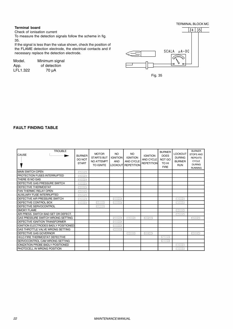
Terminal boardCheck of ionisation currentTo measure the detection signals follow the scheme in fig.35.If the signal is less than the value shown, check the position ofthe FLAME detection electrode, the electrical contacts and ifnecessary replace the detection electrode.
Model. Minimum signalApp. of detectionLFL1.322 70 µA
Fig. 35
µ
TROUBLE CAUSE BURNER
DO NOT START
MOTOR STARTS BUT NO ATTEMPT
TO IGNITE
NO IGNITION
AND LOCKOUT
NO IGNITION
AND CYCLE REPETITION
IGNITION AND CYCLE REPETITION
BURNER DOES
NOT GO TO HI FIRE
LOCKOUT DURING BURNER
RUN
BURNER STOPS AND
REPEATS CYCLE DURING
RUNNING
MAIN SWITCH OPENPROTECTION FUSES INTERRUPTEDTHERE IS NO GAS DEFECTIVE GAS PRESSURE SWITCH DEFECTIVE THERMOSTAT FAN THERMIC RELAY OPENAUXILIARY FUSE INTERRUPTEDDEFECTIVE AIR PRESSURE SWITCHDEFECTIVE CONTROL BOXDEFECTIVE SERVOCONTROLSMOKY FLAMEAIR PRESS. SWITCH BAD SET OR DEFECT.GAS PRESSURE SWITCH WRONG SETTINGDEFECTIVE IGNITION TRANSFORMERIGNITION ELECTRODES BADLY POSITIONEDGAS THROTTLE VALVE WRONG SETTINGDEFECTIVE GAS GOVERNORHI/LO FIRE THERMOSTAT DEFECTIVESERVOCONTROL CAM WRONG SETTINGIONIZATION PROBE BADLY POSITIONEDPHOTOCELL IN WRONG POSITION
BP - Pump motor remote contactor coilBV - Fan motor remote contactor coilCAP - Pump motor auxiliary contacts contactorCM - Manual operation switch 0) off 1) gas 2) light oilCP - Pump motor contactorCR1/2 - Relay contactsCTP - Pump motor overload contactsCTV - Fan motor contactsCV - Fan motor contactorEV1 - Gas electro-valve upstream DUNGS DMV..EV2 - Gas electro-valve downstream DUNGS DMV..EVG1-EVG2 - Light oil electro-valve inletEVG3-EVG4 - Light oil electro-valve returnF - FusesFC - UV flame detectorIG - Main switchL - PhaseLAF - Burner in high flame indicator lightLB - Burner lockout indicator lightLBF - Burner in low flame indicator lightLEV1 - Indicator light for opening of electro-valve EV1LEV2 - Indicator light for opening of electro-valve EV2LEVG - Indicator light for opening of electro-valves light oilLFL1.322 - LANDIS flame monitor deviceLPGMIN - Indicator light for presence of gas in the networkLS - Indicator light for burner in stand-by (STAND-BY)LSPG - Indicator light for leakage of valvesLT - Indicator light for fan overload trippedLTA - Ignition transformer indicator lightMA - Supply terminal blockMC - Terminal block for connection of burner componentsMP - Pump motorMV - Fan motorN - NeutralPA - Combustion air pressure switchPGMAX - High gas pressure switch (where supplied, remove the bridge between
terminal 156 and 158 in terminal block MC)PGMIN - Low gas pressure switchPOMAX - High light oil pressure switchPOMIN - Low light oil pressure switchPS - Lockout reset buttonR1/2 - Auxiliary relaySQL33 - LANDIS servo control for air damperST - Series thermostats or pressure switchesTA - Ignition transformerTAB - High/low thermostat (where supplied, remove the bridge between
terminals 6 and 7 in terminal block MA)TP - Pump motor thermalTV - Fan motor thermalVPS504 - Dungs valve leakage monitor device (where supplied, remove the bridge
between terminal 177 and 178 in terminal block MC)
SERVO CONTROL CAMSY1 - High flameY2 - Start-up and Ignition gas or light oil flameY3 - Low flame
WARNING :1 - Electrical supply 400V 50Hz 3N a.c.2 - Do not reverset phase with neutral3 - Ensure burner is properly earthed
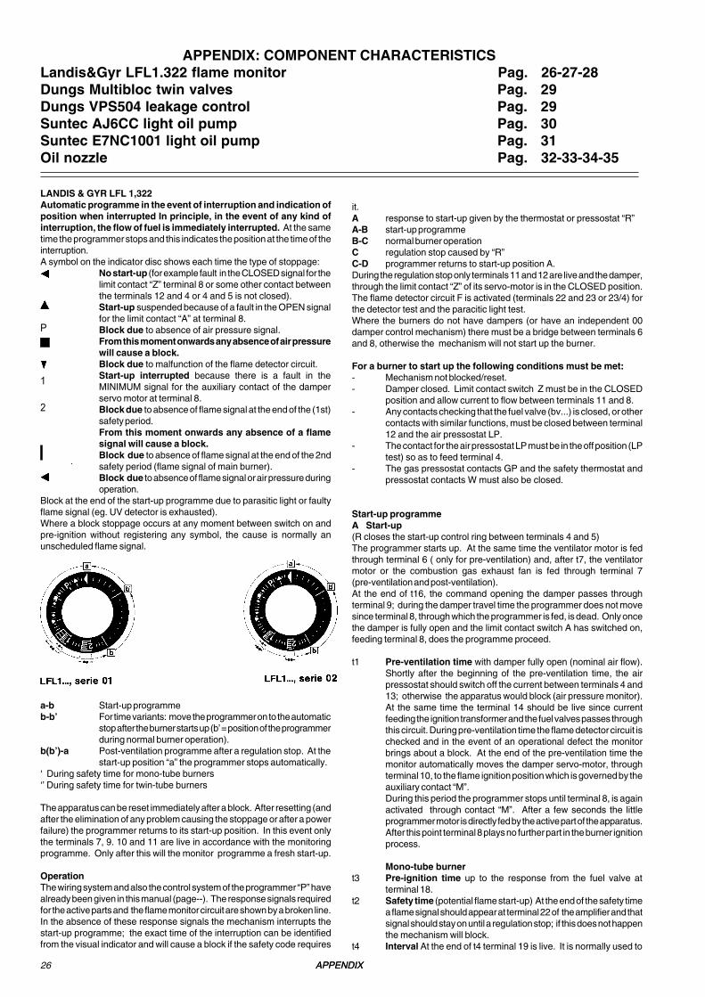
it.A response to start-up given by the thermostat or pressostat “R”A-B start-up programmeB-C normal burner operationC regulation stop caused by “R”C-D programmer returns to start-up position A.During the regulation stop only terminals 11 and 12 are live and the damper,through the limit contact “Z” of its servo-motor is in the CLOSED position.The flame detector circuit F is activated (terminals 22 and 23 or 23/4) forthe detector test and the paracitic light test.Where the burners do not have dampers (or have an independent 00damper control mechanism) there must be a bridge between terminals 6and 8, otherwise the mechanism will not start up the burner.
For a burner to start up the following conditions must be met:- Mechanism not blocked/reset.- Damper closed. Limit contact switch Z must be in the CLOSED
position and allow current to flow between terminals 11 and 8.- Any contacts checking that the fuel valve (bv...) is closed, or other
contacts with similar functions, must be closed between terminal12 and the air pressostat LP.
- The contact for the air pressostat LP must be in the off position (LPtest) so as to feed terminal 4.
- The gas pressostat contacts GP and the safety thermostat andpressostat contacts W must also be closed.
Start-up programmeA Start-up(R closes the start-up control ring between terminals 4 and 5)The programmer starts up. At the same time the ventilator motor is fedthrough terminal 6 ( only for pre-ventilation) and, after t7, the ventilatormotor or the combustion gas exhaust fan is fed through terminal 7(pre-ventilation and post-ventilation).At the end of t16, the command opening the damper passes throughterminal 9; during the damper travel time the programmer does not movesince terminal 8, through which the programmer is fed, is dead. Only oncethe damper is fully open and the limit contact switch A has switched on,feeding terminal 8, does the programme proceed.
t1 Pre-ventilation time with damper fully open (nominal air flow).Shortly after the beginning of the pre-ventilation time, the airpressostat should switch off the current between terminals 4 and13; otherwise the apparatus would block (air pressure monitor).At the same time the terminal 14 should be live since currentfeeding the ignition transformer and the fuel valves passes throughthis circuit. During pre-ventilation time the flame detector circuit ischecked and in the event of an operational defect the monitorbrings about a block. At the end of the pre-ventilation time themonitor automatically moves the damper servo-motor, throughterminal 10, to the flame ignition position which is governed by theauxiliary contact “M”.During this period the programmer stops until terminal 8, is againactivated through contact “M”. After a few seconds the littleprogrammer motor is directly fed by the active part of the apparatus.After this point terminal 8 plays no further part in the burner ignitionprocess.
Mono-tube burnert3 Pre-ignition time up to the response from the fuel valve at
terminal 18.t2 Safety time (potential flame start-up) At the end of the safety time
a flame signal should appear at terminal 22 of the amplifier and thatsignal should stay on until a regulation stop; if this does not happenthe mechanism will block.
t4 Interval At the end of t4 terminal 19 is live. It is normally used to
LANDIS & GYR LFL 1,322Automatic programme in the event of interruption and indication ofposition when interrupted In principle, in the event of any kind ofinterruption, the flow of fuel is immediately interrupted. At the sametime the programmer stops and this indicates the position at the time of theinterruption.A symbol on the indicator disc shows each time the type of stoppage:
No start-up (for example fault in the CLOSED signal for thelimit contact “Z” terminal 8 or some other contact betweenthe terminals 12 and 4 or 4 and 5 is not closed).Start-up suspended because of a fault in the OPEN signalfor the limit contact “A” at terminal 8.Block due to absence of air pressure signal.From this moment onwards any absence of air pressurewill cause a block.Block due to malfunction of the flame detector circuit.Start-up interrupted because there is a fault in theMINIMUM signal for the auxiliary contact of the damperservo motor at terminal 8.Block due to absence of flame signal at the end of the (1st)safety period.From this moment onwards any absence of a flamesignal will cause a block.Block due to absence of flame signal at the end of the 2ndsafety period (flame signal of main burner).Block due to absence of flame signal or air pressure duringoperation.
Block at the end of the start-up programme due to parasitic light or faultyflame signal (eg. UV detector is exhausted).Where a block stoppage occurs at any moment between switch on andpre-ignition without registering any symbol, the cause is normally anunscheduled flame signal.
a-b Start-up programmeb-b’ For time variants: move the programmer on to the automatic
stop after the burner starts up (b’ = position of the programmerduring normal burner operation).
b(b’)-a Post-ventilation programme after a regulation stop. At thestart-up position “a” the programmer stops automatically.
‘ During safety time for mono-tube burners‘’ During safety time for twin-tube burners
The apparatus can be reset immediately after a block. After resetting (andafter the elimination of any problem causing the stoppage or after a powerfailure) the programmer returns to its start-up position. In this event onlythe terminals 7, 9. 10 and 11 are live in accordance with the monitoringprogramme. Only after this will the monitor programme a fresh start-up.
OperationThe wiring system and also the control system of the programmer “P” havealready been given in this manual (page--). The response signals requiredfor the active parts and the flame monitor circuit are shown by a broken line.In the absence of these response signals the mechanism interrupts thestart-up programme; the exact time of the interruption can be identifiedfrom the visual indicator and will cause a block if the safety code requires
P
1
2
27APPENDIX
feed a fuel valve at auxiliary contact “V” of the damper servomotor.t5 Interval At the end of t5 terminal 20 is live. At the same time the
monitor outlets from 9 and 11 and terminal 8 into the active part ofthe apparatus are kept galvanically separated so as to protect themonitor itself from recovery voltage through the capacity regulatorcircuit.
Twin-tube burners (**)t3 Preignition time up to the all clear to the pilot burner valve at
terminal 17.t2 1st safety time (potential pilot flame) At the end of the safety time
a flame signal should appear at terminal 22 of the amplifier and thatsignal should stay on until a regulation stop; if it does not theapparatus will block.
t4 Interval Until the all clear to the fuel valve at terminal 19 for the firstflame of the main burner.
t9 2nd safety time At the end of the second safety time the principalburner should be lit by the pilot. At the end of this period terminal17 is dead and therefore the pilot burner will be out.
t5 Interval At the end of t5 terminal 20 is live. At the same time themonitor outlets from 9 and 11 and at terminal 8 into the active partthe apparatus are galvanically separated so as to protect theapparatus itself from recovery voltage through the capacity regulatorcircuit.When the capacity regulator LR at terminal 20 gives the all clear,the start-up programme for the apparatus comes to an end. Withtime variants the programmer stops either immediately or at theend of a set time, without effecting the position of the contacts.
B Operational position of the burner
B-C Burner operation (production of heat)While the burner is working the capacity regulator controls the damperaccording to the demand for heat, by means of the positioning at nominalload of the auxiliary contact “V” of the damper servocontrol.
C Regulation stop for operation of “R”When there is a regulation stop the fuel valves immediately close. At thesame time the programmer starts to programme:t6 Post-ventilation time (post-ventilation with the ventilator “G” at
terminal 7). Shortly after beginning of the post-ventilation timeterminal 10 becomes live and moves the damper to the “MIN”position. The full closure of the damper only happens towards theend of the post-ventilation time and is prompted by an automaticsignal from terminal 11
t13 Allowable post-ignition timeDuring this time the flame monitor circuit may still receive a flamesignal without the apparatus blocking.
D-A End of automatic programmeAt the end of t6, at the point where the programmer and the automaticcontacts have reverted to the starter position, the detector test restarts.During an operational stop even an unscheduled flame signal lasting a fewseconds can cause a block so during this period an NTC in the circuit actsas retarder. This means that brief unscheduled influences cannot causea block.(**) Times t3, t2 and t4 only apply to safety devices in the series 01.
Technical characteristicsMains voltage 220V-15%...
No.451915070External fuse max. 16AInterference N-VDE0875Flow permitted at terminal 1 5A (DIN 0660 AC3)Flow permitted at control terminals 4A (DIN 0660 AC3)
Flow at monitor contacts:input at terminals 4 & 5 1A,250Vinput at terminals 4 & 11 1A,250Vinput at terminals 4 & 14 Flow at terminals 16 &19 min.1A,250VEmplacement AnyProtection IP40Permitted ambient temp: -20...+60°CMin.temperature (trans/storage) -50°C
UV monitorVoltage in UV detectornormal working: 330V±10%, test:
380V±10%Detector current, min. reqmt* 70µAMax. detector current,normal working: 630A, test: 1300AMax.length of connecting cable
- normal cable(laid separately**): 100m- armoured able(high frequency)protected at terminal 22: 200m
Weight QRA2: 60g; QRA10: 450g. Ignition spark monitor with QRE1 series 02 detectorMinimum detector current 30µA* Connect up in parallel to the measuring device a condenser100µF,10...25V.** The wire connecting up the detector electrode should not be in the samesleeve as the other conductor wires.
Operating timest7 initial delay for ventilator G2 2t16 initial delay for Damper OPEN response 4t11 travel time for damper anyt10 initial delay for air presure monitor 8t1 pre-ventilation time with damper open 36t12 travel time for damper to MIN position anyt3t3' pre-ignition time t3 4
t3' -t2t2' safety time (1st safety time for burners
with intermittent pilot lighter t2 2t2' -
t4t4' interval between start of t2 and response tovalve at terminal 19 t4 6
t4' -t9 2nd safety time for burners with
intermittent pilot lighter 2t5 interval between end of t4 and
response at terminal 20 10t20 interval before programmer cuts out
after start-up 32- Duration of start-up 30t6 Post-ventilation time (G2 only) 10t13 Permitted post-ignition time 10
28
Key:A limit contact switch for damper OPEN
positionAI advance signal of a blockAR main relay (working network) with
contacts “ar”AS Monitor fuseBR block relay with “br” contactsBV fuel valveEK reset buttonFE detector electrode of ionisation circuitFR flame relay with “fr” contactsG ventilator motor or burner motorGP gas pressostatH main interruptor switchL block stoppage LEDLK damperLP air pressostatLR safety regulatorM auxiliary contact switch for damper
“MIN” positionQRA UV detectorQRE ignition spark detectorR thermostat or pressostatS fuseSA damper servo-motorSM synchronous programmer motorV flame signal amplifierV in case of servo-motor: auxiliary contact
for response to fuel valve re damperposition
W safety pressostat or thermostatZ ignition transformerZ in case of servomotor: end of limit
contact switch for damper CLOSEDposition
ZBV pilot burner fuel valve° for mono-tube burners°° for twin-tube burners
(1 )input for raising QRA detector voltageto test level
(2) input for excitation of flame relay duringflame detector t e s tcircuit (contact XIV) and during safetytime (contact I V)
(3) Do not press EK for more than 10seconds
Programmer diagramt1 pre-ventilation timet2 safety time*t2' 1st safety timet3 pre-ignition time*t3' pre-ignition timet4 interval for creating current between
terminals 18 and 19*t4' interval for creating current between
terminals 17 and 19t5 interval for creating current between
terminals 19 and 20t6 post-ventilation timet7 interval between response and current
created at terminal 7t8 duration of start-up*t9 2nd safety timet10 interval before air pressure monitoring
beginst11 damper opening travel timet12 damper closure travel timet13 permissible post-combustion timet16 initial delay of damper OPEN responset20 interval before programmer
automatically stops* These times are valid with the use of a series01 safety device for monitoring burners withintermittent pilot lighter.
APPENDIX
29
Absorbed power: during pumping time:approx.15-20 VAin service: SVA
Fuse at inlet 10 A rapid or 6A T
Interchangeable fuse
incorporated in coverof casing 6.3 AT(din 41662)
Power at relay output 4A
Test voltage 2 kW eff. cos q =1
Protection IP40
Permissible ambienttemperature -15 C up to + 70C
Duration of operation upto authorization signalapprox. 10-30 s. ca 25-30sInstallation position horizontal, vertical,
provided notsuspendedLimit value 30 l/hDuration of control operation 100% EDMax.No.0f test cycles 20/h 30/h
Protection IP54Intervention time 100%EDElectrical wiring Lead PG11, standard DIN 43650plug on request
VPS504 LEAK DETECTION FOR MULTIBLOCK GAS UNIT
Technical data VPS5O4 VDK301Series 02 Series O5
Operating pressure 20-500 mbar 0-50 mbar
Max. test volume 4.0 l 0.6 l
Test pressure 100 mbaroperating pressure +20 mbar ±10
Nominal voltage -(AC)230V-15% -(AC)220V-15%v up to up to
-(AC)240V-15% -(AC)240V +6%
Frequency: 50 Hz
APPENDIX
30
SUNTEC AJ6CC LIGHT OIL PUMP
Applications
Light Oil - flow up to 150 1/h - Normally used with on-lineelectromagnetic valve
- Twin-pipe system - Single-pipe system - System for transportinglow presurelight oil with conversion kit available separately (for AJ version2).
Technical dataGeneralMounting Flange (DIN 24220)Threaded connectors ntake and outlet R 1/4"
(DIN259)Delivery R 1/8"Manometer R 1/8"Vacuum gauge R 1/8"
Valve function To regulate pressure with cut-off
Filter 46,1 cm2 (120-150 mesh)Cam ø11mmBy-pass plug Inserted for twin-tube system
Removed for single-pipesystem
Weight 1,8kgRotation and delivery position vis Ó vis the shaft
A - Clockwise/RH deliveryB - Anticlockwise/LH deliveryC - Anticlockwise/RH delivery
OperationThe gear assembly sucks in the oil through the filter andtransfers it under pressure to the valve. When the springreaches the calibrated figure the oil pressure forces the pistonhead back allowing the oil to pass along the line to the nozzle.Any oil surplus to the flow at the nozzle is unloaded through thevalve to the return tube and back to the tank (twin-pipeinstallation) or to the suction chamber (single-pipe installation).When the motor stops there is a drop in the pressure and thisallows the spring to give the piston a sharp push forwards, thusclosing the aperture to the nozzle tube (cut-off function). Eachstroke of the piston automatically drives out the air - twin- tubesystem - and accelerates the movement of the piston and thusensures a quicker cut-off.
Oil under suction
Oil under pressure
Unused oil - totank or suction
Pressureregulator
Pressure-gaugeconnection
to nozzle
Shaft seal
Vacuum - gaugeconnection
IntakeReturn
By-passplug "P"
Return tosuction
Single-pipe installation Twin-pipe installation
APPENDIX
31
E7NC1001 Light Oil pump
Applications- Light Oil- Flow up to 300 1/h- Normally used with a on-line electromagnetic valve- Twin-tube system- Mono-tube system
Technical DataInstallation Flange (DIN24220)Threaded connection:Intake and outlet R 1/2" (DIN259)Delivery R 1/4"Pressure R 1/8"Internal by-pass R 1/8" NPTFValve function Pressure regulation and
cut-outFilter 52cm2(30 Mesh)Shaft seal diaphragm: friction bearing
on the shaft slides on itralloyring in the diaphragmreinforced with fibreglass.
By-pass plug Must be inserted for twin-pipe systems andremoved for single-pipesystems
Rotational direction anddelivery position viv à visthe shaft C - anti-clockwise rotation/
0,35 Bars recommended to avoid separation of gas andoil
OperationThe gear assembly sucks in the oil through the filter andtransfers it under pressure to the valve.When the spring reaches the calibrated figure the oil presureforces thepiston head back and this allows the oil to pass alongthe line to the nozzle.Any oil in excess of the nozzle flow is unloaded through thevalve to the return line back to the tank (twin-pipe systems) orto the suction chamber (single-pipe systems).When the motor stops this brings about a drop in pressure andthis allows the spring to force the piston sharply forward thusclosing the aperture to the nozzle tibe (cut-off function).
Oil under suction
Oil under pressure
Oil not used in thesuction chamber
Oil returned totank
Filter Intake from tank
Intake
Pinion Rotor
To thenozzle Delivery plug/cap
Delivry connectionPistonPressure
Suntec Rota-Roll pump
Pressure settingBack connector
For single-piperemove gland andinsert plug Backconnector in bore