Dual Link Film still continues to dominate within high-end production as the main acquisition medium, despite all the advances in digital signal processing. Although the transition to digital is making advances with various applications such as digital cinema and high-end post production such as film to data transfers, visual effects and color correction. The quest is therefore higher and higher image resolutions such as 2K or 4K image formats that more emulate the “film look” of the material. By having a high resolution digital distribution master of the material, we now have ready access to the wide range of duplication formats for the program - from Digital Cinema to HD or SD formats. Introduction Application Note
Transcript
Dual Link
Film still continues to dominate within high-end production as the main acquisition medium, despiteall the advances in digital signal processing. Although the transition to digital is making advanceswith various applications such as digital cinema and high-end post production such as film to datatransfers, visual effects and color correction. The quest is therefore higher and higher image resolutions such as 2K or 4K image formats that more emulate the “film look” of the material. By having a high resolution digital distribution master of the material, we now have ready access to the wide range of duplication formats for the program - from Digital Cinema to HD or SD formats.
Introduction
Application Note
Dual LinkApplication Note
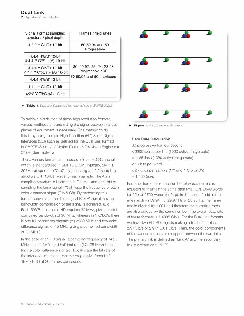
To achieve distribution of these high resolution formats, various methods of transmitting the signal between variouspieces of equipment is necessary. One method to do this is by using multiple High Definition (HD) Serial DigitalInterfaces (SDI) such as defined for the Dual Link formats in SMPTE (Society of Motion Picture & Television Engineers)372M (See Table 1.)
These various formats are mapped into an HD-SDI signalwhich is standardized in SMPTE 292M. Typically, SMPTE292M transports a Y'C'bC'r signal using a 4:2:2 samplingstructure with 10-bit words for each sample. The 4:2:2sampling structure is illustrated in Figure 1 and consists ofsampling the luma signal (Y') at twice the frequency of eachcolor difference signal (C'b & C'r). By performing this format conversion from the original R'G'B' signal, a simplebandwidth compression of the signal is achieved. (E.g.Each R'G'B' channel in HD requires 30 MHz, giving a totalcombined bandwidth of 90 MHz, whereas in Y'C'bC'r, thereis one full bandwidth channel (Y') of 30 MHz and two colordifference signals of 15 MHz, giving a combined bandwidthof 60 MHz.)
In the case of an HD signal, a sampling frequency of 74.25MHz is used for Y' and half that rate (37.125 MHz) is usedfor the color difference signals. To calculate the bit rate ofthe interface, let us consider the progressive format of1920x1080 at 30 frames per second.
Data Rate Calculation
30 progressive frames/ second
x 2200 words per line (1920 active image data)
x 1125 lines (1080 active image data)
x 10 bits per word
x 2 words per sample (1Y' and 1 C'b or C'r)
= 1.485 Gb/s
For other frame rates, the number of words per line isadjusted to maintain the same data rate. (E.g. 2640 wordsfor 25p or 2750 words for 24p). In the case of odd framerates such as 59.94 Hz, 29.97 Hz or 23.98 Hz, the framerate is divided by 1.001 and therefore the sampling ratesare also divided by the same number. The overall data rateof these formats is 1.4835 Gb/s. For the Dual Link formats we have two HD-SDI signals making a total data rate of2.97 Gb/s or 2.97/1.001 Gb/s. Then, the color componentsof the various formats are mapped between the two links.The primary link is defined as “Link A” and the secondarylink is defined as “Link B”.
2 www.tektronix.com
Table 1. Dual Link Supported formats defined in SMPTE 372M.
Figure 1. 4:2:2 Sampling Structure.
Signal Format sampling Frames / field ratesstructure / pixel depth
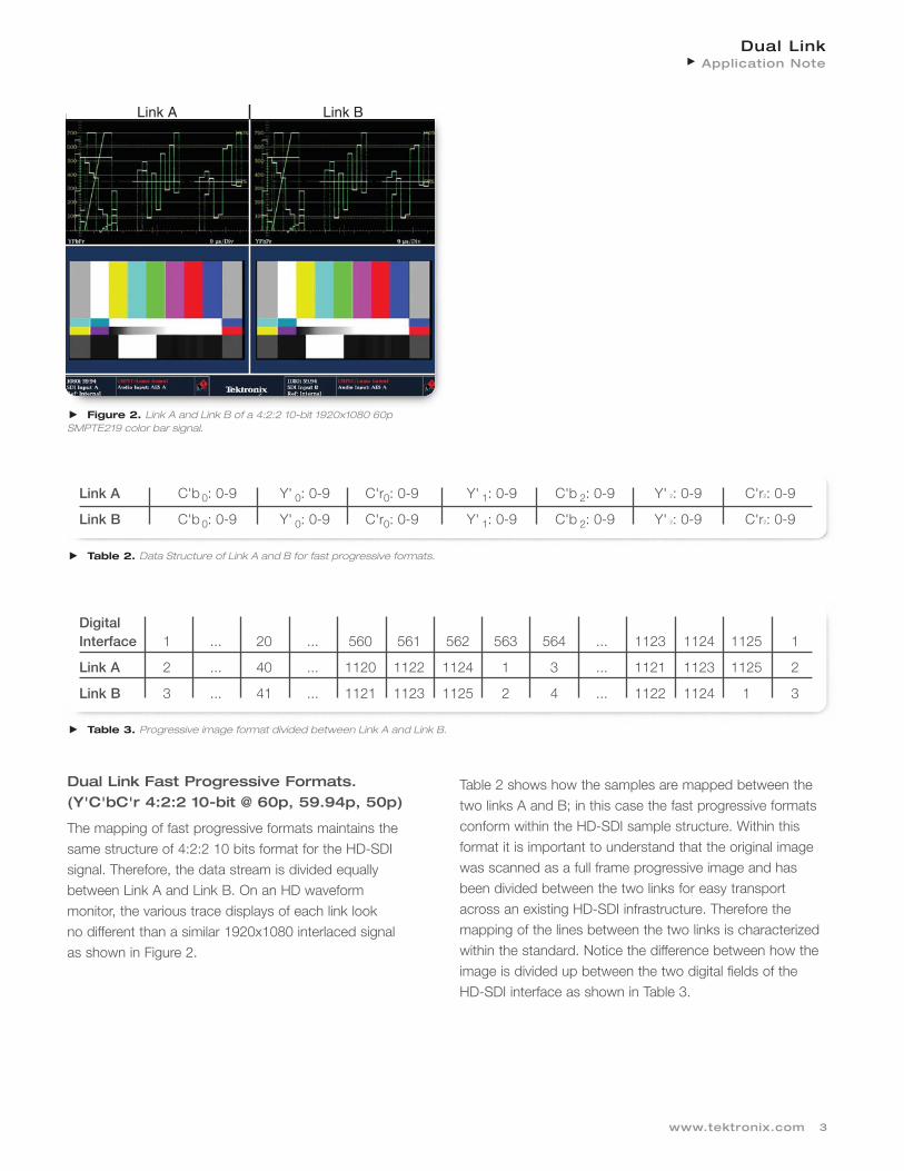
Table 2. Data Structure of Link A and B for fast progressive formats.
Dual Link Fast Progressive Formats.(Y'C'bC'r 4:2:2 10-bit @ 60p, 59.94p, 50p)
The mapping of fast progressive formats maintains thesame structure of 4:2:2 10 bits format for the HD-SDI signal. Therefore, the data stream is divided equallybetween Link A and Link B. On an HD waveform monitor, the various trace displays of each link look no different than a similar 1920x1080 interlaced signal as shown in Figure 2.
Table 2 shows how the samples are mapped between thetwo links A and B; in this case the fast progressive formatsconform within the HD-SDI sample structure. Within thisformat it is important to understand that the original imagewas scanned as a full frame progressive image and hasbeen divided between the two links for easy transportacross an existing HD-SDI infrastructure. Therefore themapping of the lines between the two links is characterizedwithin the standard. Notice the difference between how theimage is divided up between the two digital fields of theHD-SDI interface as shown in Table 3.
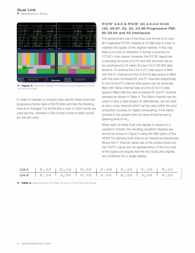
The predominant use of the Dual Link format is to carry film originated R'G'B' material at 23.98p/24p in order tomaintain the quality of the original material. In this way there is no loss of resolution in format conversion toY'C'bC'r color space. However, the R'G'B' signal has a sampling structure of 4:4:4 and this structure has to be constrained to fit within the two 4:2:2 HD-SDI datastreams. To achieve this Link A [Y'] data space is filled with the G' channel and the [C'b/C'r] data space is filledwith the even-numbered B' and R' channels respectively. In Link B the [Y'] channel data space can be optionally filled with Alpha channel data and the [C'b/C'r] data space is filled with the odd-numbered B' and R' channelsamples as shown in Table 4. The Alpha channel can beused to carry a data stream or, alternatively, can be used to carry a key channel which can be used within the postproduction process for digital compositing. If the Alphachannel is not present then its value should be set to blanking level of 64H.
When each of these Dual Link signals is viewed on a waveform monitor, the resulting waveform displays areformed as shown in Figure 3 using the SIM option of theWFM7120 allowing both links to be viewed simultaneously.Notice the Y' channel values are of the correct levels butthe C'b/C'r values are not representative of the true level of the signal and require that the two Dual Links signals are combined into a single display.
4 www.tektronix.com
Figure 3. Waveform displays of Dual Link A and B signal for R'G'B' (A) 4:4:4:4 format.
Link A B' 0: 0-9 G' 0: 0-9 R'0: 0-9 G' 1: 0-9 B' 2: 0-9 G' 2: 0-9 R'2: 0-9
Link B B' 1: 0-9 A 0: 0-9 R'1: 0-9 A 1: 0-9 B' 3: 0-9 A 2: 0-9 R'3: 0-9
Table 4. Data Structure for R'G'B' (A) 4:4:4:4 10-bit Dual Link format.
In order to maintain a constant data rate for these three fastprogressive frame rates of 60/59.94p and 50p the blankinginterval is changed. For 60/59.94p a total of 2200 words areused per line, whereas in 50p format a total of 2640 wordsper line are used.
The structure of this format is similar to R'G'B' (A) 4:4:4:4as shown in Table 5. Link A [Y'] data space is filled with theY' channel and the [C'b/C'r] data space is filled with theeven-numbered C'b and C'r channels respectively. In Link Bthe [Y'] channel data space can be optionally filled withAlpha channel data and the [C'b/C'r] data space is filledwith the odd-numbered C'b and C'r channel samples.However since this format conforms to the Y'C'bC'r formatof the HD-SDI data stream, Link A is representative of the
signal and can be viewed on a HD waveform monitor. Thetrace of the Link B signal is dependent on the value presentin the Alpha channel, as shown in the picture tile in Figure4. With the waveform monitor, it is possible to view theAlpha channel waveform traces by selecting the Alphachannel view in the picture menu of the instrument. In theWFM7120/7020, the signals can also be down-convertedfrom the Dual Link signal into a single HD-SDI signal. Thissignal can be output from the waveform monitor for use insimple monitoring, without the additional need for a DualLink picture monitor.
Figure 4. Waveform displays of Dual Link A and B signals for Y'C'bC'r(A) 4:4:4:4 10-bit format.
Link B C'b 1: 0-9 A 0: 0-9 C'r1: 0-9 A 1: 0-9 C'b 3: 0-9 A 2: 0-9 C'r 3: 0-9
Table 5. Data Structure for Y'C'bC'r(A) 4:4:4:4 Dual Link format.
Dual LinkApplication Note
6 www.tektronix.com
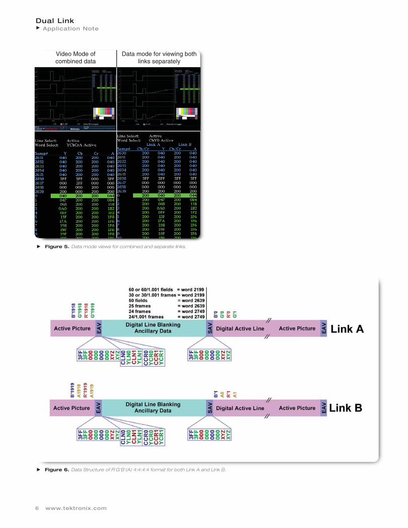
Figure 6. Data Structure of R'G'B'(A) 4:4:4:4 format for both Link A and Link B.
Figure 5. Data mode views for combined and separate links.
Video Mode of combined data
Data mode for viewing both links separately
Data Structure
Within the WFM7020 or WFM7120, with the DAT optioninstalled, the user can view the data list under the measuremenu and can see the structure of each link in data modeor the resulting combined data in the video mode as shownin Figure 5. This allows the user to see the combination of
the data values between the two links and to verify thesample length and structure of the stream. Table 6 showsthe total number of words that are present within the various frame rates and Figure 6 shows how the data issplit across the two links for an R'G'B'(A) 4:4:4:4 formats.These same views can be applied to the other formats.
Dual LinkApplication Note
7www.tektronix.com
Frame/Field Rate Total words per line Total active words per line
60 or 60/1.001 fields 2200 192030 or 30/1.001 frames
50 fields 2640 192025 frames
24 or 24/1.001 frames 2750 1920
Table 6. Total number of words per line for various frame rates.
To achieve a greater dynamic range for the signal, a 12-bitdata format can be accommodated within the Dual Linkstandard. The problem here is that the data structure ofeach link conforms to 10-bit words. Therefore, a methodhas been defined to carry the 12-bit data across multiple10-bit words. In the case of R'G'B' 4:4:4 12-bits, the mostsignificant bits (MSBs) 2-11 are carried with the 10-bitwords. The additional two bits for each of the R'G'B'
channels are combined into the Y' channel of Link B asshown in Table 7. Link A carries the G' channel bits 2-11and even sample values of B' and R' bits 2-11. In Link Bthe alpha channel is replaced by the combined bits 0-1 ofthe R'G'B' samples. The odd samples of the B' and R' bits2-11 are carried within the [C'b/C'r] words. The combinedR'G'B' 0-1 data is mapped into the 10-bit word as definedin Table 8, where EP represent even parity for bits 7-0, thereserved values are set to zero and bit 9 is not bit 8.
8 www.tektronix.com
Link A B' 0: 2-11 G' 0: 2-11 R' 0: 2-11 G' 1: 2-11 B' 2: 0-9 G' 2: 2-11 R' 2: 2-11
Link B B' 1: 2-11 R'G'B'0: 0-1 R'1: 2-11 R'G'B'1: 0-1 B' 3: 0-9 R'G'B' 2: 0-1 Rv3: 2-11
Table 7. Channel representation for RGB 12-bit.
Word 9 8 7 6 5 4 3 2 1 0(MSB) (LSB)
Not EP G'n:1 G'n:0 B'n:1 B'n:0 R'n:1 R'n:0 Reserved ReservedB8
Table 8. Mapping structure for R'G'B' 0-1.
Bit Number
Dual LinkApplication Note
Dual LinkApplication Note
9www.tektronix.com
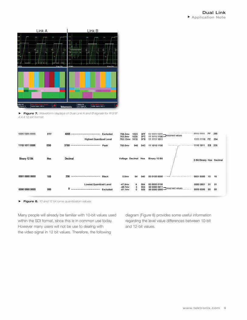
Figure 8. 10 and 12 bit luma quantization values.
Many people will already be familiar with 10-bit values usedwithin the SDI format, since this is in common use today.However many users will not be use to dealing with the video signal in 12 bit values. Therefore, the following
diagram (Figure 8) provides some useful information regarding the level value differences between 10-bit and 12-bit values.
Link A Link B
Figure 7. Waveform displays of Dual Link A and B signals for R'G'B' 4:4:4 12-bit format.
Figure 9 Waveform displays of Dual Link A and B signals for Y'C'bC'r 4:4:4 12-bit format.
Link A Link B
Dual LinkApplication Note
10 www.tektronix.com
Link A C'b 0: 2-11 Y'0: 2-11 C'r0: 2-11 Y'1: 2-11 C'b 2: 0-9 Y'2: 2-11 R'2: 2-11
The structure of the Y'C'bC'r 12-bit data is similar to theG'B'R' 12-bit structure where G' is equivalent to Y', B' isequivalent to C'b and R' is equivalent to C'r. Table 9 shows
the channel mapping for the Y'C'bC'r samples and Table10 shows the bit 0-1 mapping structure within the 10-bitdata word. Figure 9 shows the waveforms of both linksusing the SIM option on the WFM7120.
For those applications that need to transport the Alphachannel and YCbCr 12-bit data, the following data streamis defined for 12-bit within the constraints of the 10-bit SDIstructure. The MSBs for Y'C'bC'r bits 2-11 are carried in
Link A and conform to the C'bY'C'rY'* multiplex of the SDIsignal. The 10-bit Alpha channel and the LSBs of theY'nC'bnC'rn and Yn+1 are carried in Link B and mappedaccording to the Table 11. The 0-1 bits of the Y'C'bC'rsamples are carried in the 10-bit word as defined in Table12 and the additional Y'* samples are mapped as shown inTable 13.
Dual LinkApplication Note
11www.tektronix.com
Word 9 8 7 6 5 4 3 2 1 0(MSB) (LSB)
Not EP Y'n:1 Y'n:0 C'b n:1 C'b n:0 C'r n:1 C'r n:0 Reserved ReservedB8
Bit Number
Table 12. Mapping structure for Y'C'bC'r 0-1.
Word 9 (MSB) 8 7 6 5 4 3 2 1 0 (LSB)
Not B8 EP Y'n:1 Y'n:0 Reserved Reserved Reserved Reserved Reserved Reserved
Bit Number
Table 13. Mapping structure for Y' 0-1.
Dual LinkApplication Note
12 www.tektronix.com
Dual LinkApplication Note
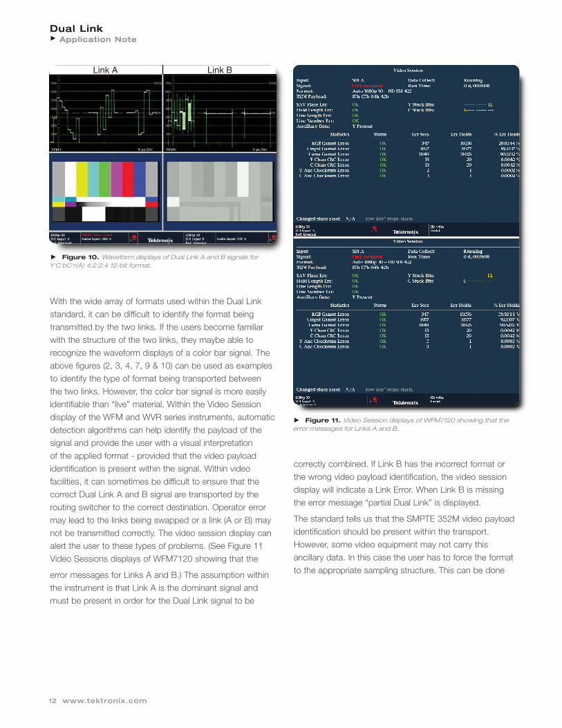
With the wide array of formats used within the Dual Linkstandard, it can be difficult to identify the format beingtransmitted by the two links. If the users become familiarwith the structure of the two links, they maybe able to recognize the waveform displays of a color bar signal. Theabove figures (2, 3, 4, 7, 9 & 10) can be used as examplesto identify the type of format being transported between the two links. However, the color bar signal is more easilyidentifiable than “live” material. Within the Video Sessiondisplay of the WFM and WVR series instruments, automaticdetection algorithms can help identify the payload of thesignal and provide the user with a visual interpretation of the applied format - provided that the video payload identification is present within the signal. Within video facilities, it can sometimes be difficult to ensure that thecorrect Dual Link A and B signal are transported by therouting switcher to the correct destination. Operator errormay lead to the links being swapped or a link (A or B) maynot be transmitted correctly. The video session display canalert the user to these types of problems. (See Figure 11Video Sessions displays of WFM7120 showing that the
error messages for Links A and B.) The assumption within the instrument is that Link A is the dominant signal andmust be present in order for the Dual Link signal to be
correctly combined. If Link B has the incorrect format or the wrong video payload identification, the video sessiondisplay will indicate a Link Error. When Link B is missing the error message “partial Dual Link” is displayed.
The standard tells us that the SMPTE 352M video payloadidentification should be present within the transport.However, some video equipment may not carry this ancillary data. In this case the user has to force the formatto the appropriate sampling structure. This can be done
Figure 11. Video Session displays of WFM7120 showing that the error messages for Links A and B.
Figure 10. Waveform displays of Dual Link A and B signals for Y'C'bC'r(A) 4:2:2:4 12-bit format.
Link A Link B
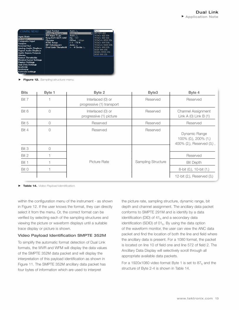
Page Sub TitleBits Byte 1 Byte 2 Byte3 Byte 4
Bit 7 1 Interlaced (0) or Reserved Reservedprogressive (1) transport
Bit 6 0 Interlaced (0) or Reserved Channel Assignmentprogressive (1) picture Link A (0) Link B (1)
Bit 5 0 Reserved Reserved Reserved
Bit 4 0 Reserved Reserved Dynamic Range100%
Bit 3 0
Bit 2 1 Reserved
Bit 1 1 Bit Depth
Bit 0 1 8-bit (0h), 10-bit (1h)
12-bit (2h), Reserved (3h)
Table 14. Video Payload Identification.
Picture Rate Sampling Structure
Dynamic Range100% (0h), 200% (1h)
400% (2h), Reserved (3h)
within the configuration menu of the instrument - as shownin Figure 12. If the user knows the format, they can directlyselect it from the menu. Or, the correct format can be verified by selecting each of the sampling structures andviewing the picture or waveform displays until a suitabletrace display or picture is shown.
Video Payload Identification SMPTE 352M
To simplify the automatic format detection of Dual Linkformats, the WVR and WFM will display the data values of the SMPTE 352M data packet and will display the interpretation of this payload identification as shown inFigure 11. The SMPTE 352M ancillary data packet hasfour bytes of information which are used to interpret
the picture rate, sampling structure, dynamic range, bit depth and channel assignment. The ancillary data packet conforms to SMPTE 291M and is identify by a data identification (DID) of 41h and a secondary data identification (SDID) of 01h. By using the data option of the waveform monitor, the user can view the ANC datapacket and find the location of both the line and field wherethe ancillary data is present. For a 1080 format, the packetis located on line 10 of field one and line 572 of field 2. TheAncillary Data Display will selectively scroll through allappropriate available data packets.
For a 1920x1080 video format Byte 1 is set to 87h and thestructure of Byte 2-4 is shown in Table 14.
Dual LinkApplication Note
13www.tektronix.com
Figure 12. Sampling structure menu.
Dual LinkApplication Note
14 www.tektronix.com
Dual LinkApplication Note
Figure 13. Ancillary Data Display of SMPTE 352M payload.
Value Picture Rate
0h No defined value
1h Reserved
2h 24/1.001
3h 24
4h Reserved
5h 25
6h 30/1.001
7h 30
8h Reserved
9h 50
Ah 60/1.001
Bh 60
Ch Reserved
Dh Reserved
Eh Reserved
Fh Reserved
Table 15. Picture Rate.
Value Sampling Rate
0h 4:2:2 [default] (YCbCr)
1h 4:4:4 (YCbCr)
2h 4:4:4 (GBR)
3h 4:2:0
4h 4:2:2:4 (YCbCrA)
5h 4:4:4:4 YCbCrA
6h 4:4:4:4 (GBRA)
7h Reserved
8h 4:2:2:4 (YCbCrD)
9h 4:4:4:4 (YCbCrD)
Ah 4:4:4:4 (GBRD)
Bh Reserved
Ch Reserved
Dh Reserved
Eh 4:4:4:4 (GBRA) 2048x1080
Fh Reserved
Table 16. Sampling structure.
The picture rate value is defined by Table 15 and the sampling structure by Table 16. With the information fromthese tables, we can then interpret the SMPTE 352M payload. For example, using the information in Figure 13from the ancillary data display, we can interpret the formatof the signal. The four bytes of the packet are 287h, 1C7h,104h, 102h. The first byte of the packet 287h indicates thatthis is a 1080 format. The second byte, 1C7h. from Table14 is separated into two parts. First, the Ch value (1100 inbinary) defines a progressive transport (1) and progressive
picture (1). Second, the picture rate is 7h, indicating a rateof 30 from Table 15. The third byte is 104h. From Table 14,the upper bit values are reserved. The lower bit value of 4h
corresponds to a 4:4:4:4 Y'C'bC'rA format as shown inTable 16. Finally the fourth byte is 102h. From Table 14, the upper value 0 represents Link A and the value of 2h
represent a 100% dynamic range with a bit depth of 12-bit. Therefore we can interpret the video payload shown in Figure 14 (Video Session Display as 1080p30 -Y'C'bC'rA 12b).
A variety of ancillary data can be sent on the two links. Forexample, embedded audio can be added to the horizontalancillary data of both links and up to 32 channels can besupported. Link A has priority over Link B which means thatthe first sixteen channels should be placed within Link A,and that the audio should not be split between the links. Inthe case of 24 channels the first 16 channels should beembedded into Link A and the other remaining eight channels embedded into Link B.
The Tektronix TG700 multi-format signal generator has the capability to generate a range of Dual Link test signals formats using the HDLG7 module. The module can up-convert a high definition signal such as an HD test signal from the HDVG7 module to an appropriate Dual Link format. The embedded audio from the HD input can also be output to the Dual Link format in this modeto provide up to 32 channels of embedded audio.
Dual Link Inter-Channel Timing
Within a video facility the two links can be routed along different paths. This can potentially introduce timing errorsbetween the two links. The SMPTE 372M standard defines
an allowable timing difference of 40 ns between the twolinks at the source of the output from the device, but doesnot define an allowable maximum difference for the timingbetween the two links. Therefore it is important to check thespecifications of equipment to see the allowable range oftiming difference at the inputs to the device and to ensurethat the electrical lengths of the paths carrying the two DualLink signals are identical. For instance, the TG700 HDLG7module allows the user to adjust the timing differencebetween the two links up to +/- 200ns. In some cases theinternal buffer within the piece of equipment maybe able toaccount for any inter-channel timing difference applied to itsinput. However, care should be taken not to exceed thespecification of the device, or the Dual Link signal may notbe combined correctly. For instance the WFM7120 has abuffer of 30 clocks. If this timing difference is exceed, a shiftwill occur between the channels and the data will not becombined correctly as shown in Figure 15. In this examplea significant amount of cable was added to link B to causethis error. Notice the Y-C shift in the picture display and thenoise within the channels on the waveform display.
Figure 15. Inter-channel Timing between Links A and B.
Dual LinkApplication Note
15www.tektronix.com
Figure 14. Video Session Display showing SMPTE352M payload.
Dual LinkApplication Note
16 www.tektronix.com
Dual LinkApplication Note
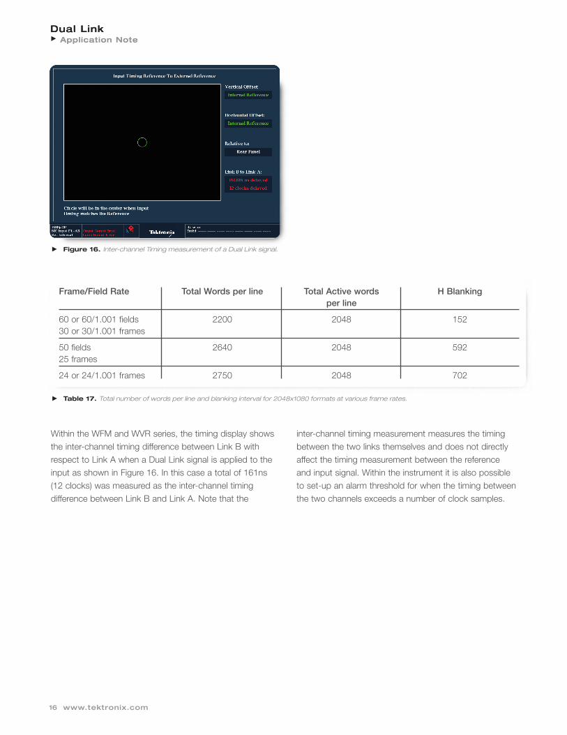
Within the WFM and WVR series, the timing display showsthe inter-channel timing difference between Link B withrespect to Link A when a Dual Link signal is applied to theinput as shown in Figure 16. In this case a total of 161ns(12 clocks) was measured as the inter-channel timing difference between Link B and Link A. Note that the
inter-channel timing measurement measures the timingbetween the two links themselves and does not directlyaffect the timing measurement between the reference and input signal. Within the instrument it is also possibleto set-up an alarm threshold for when the timing between the two channels exceeds a number of clock samples.
Figure 16. Inter-channel Timing measurement of a Dual Link signal.
Frame/Field Rate Total Words per line Total Active words H Blankingper line
60 or 60/1.001 fields 2200 2048 15230 or 30/1.001 frames
50 fields 2640 2048 59225 frames
24 or 24/1.001 frames 2750 2048 702
Table 17. Total number of words per line and blanking interval for 2048x1080 formats at various frame rates.
Dual LinkApplication Note
17www.tektronix.com
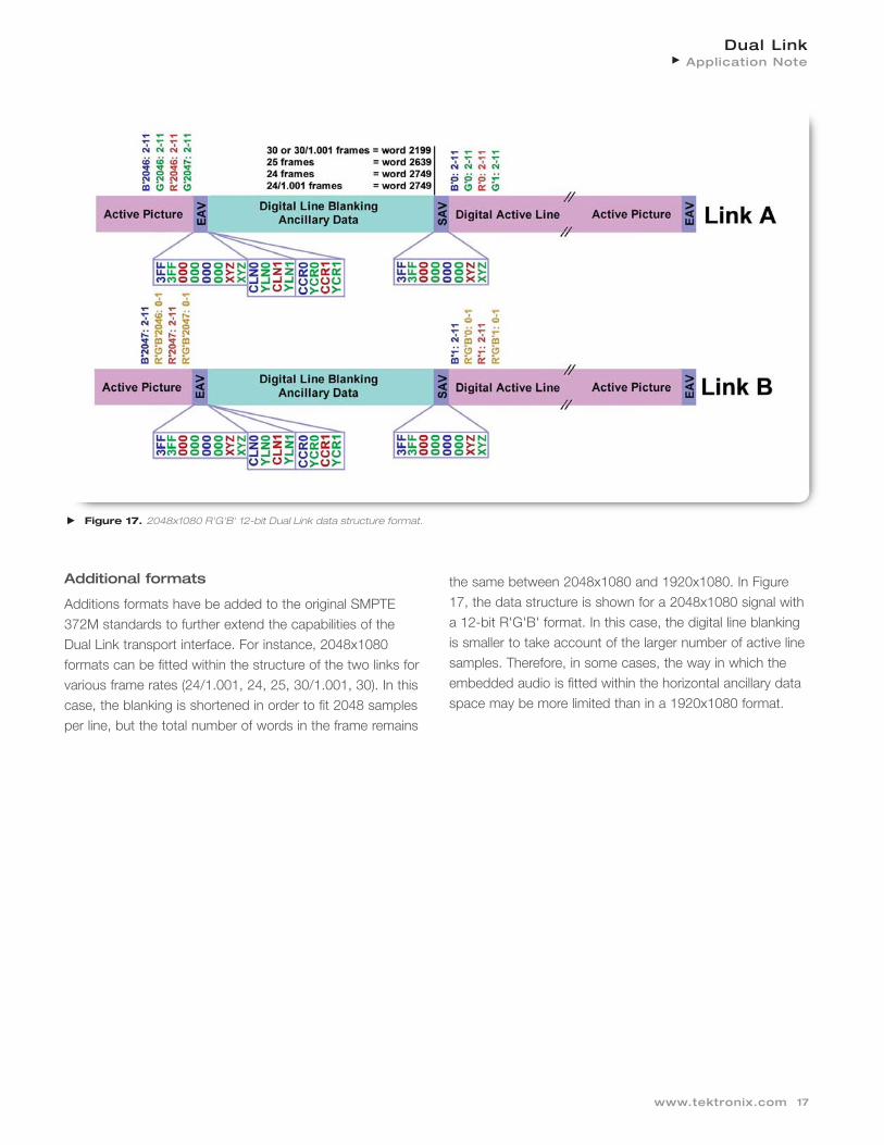
Figure 17. 2048x1080 R'G'B' 12-bit Dual Link data structure format.
Additional formats
Additions formats have be added to the original SMPTE372M standards to further extend the capabilities of theDual Link transport interface. For instance, 2048x1080 formats can be fitted within the structure of the two links forvarious frame rates (24/1.001, 24, 25, 30/1.001, 30). In thiscase, the blanking is shortened in order to fit 2048 samplesper line, but the total number of words in the frame remains
the same between 2048x1080 and 1920x1080. In Figure17, the data structure is shown for a 2048x1080 signal witha 12-bit R'G'B' format. In this case, the digital line blankingis smaller to take account of the larger number of active linesamples. Therefore, in some cases, the way in which theembedded audio is fitted within the horizontal ancillary dataspace may be more limited than in a 1920x1080 format.
Dual LinkApplication Note
18 www.tektronix.com
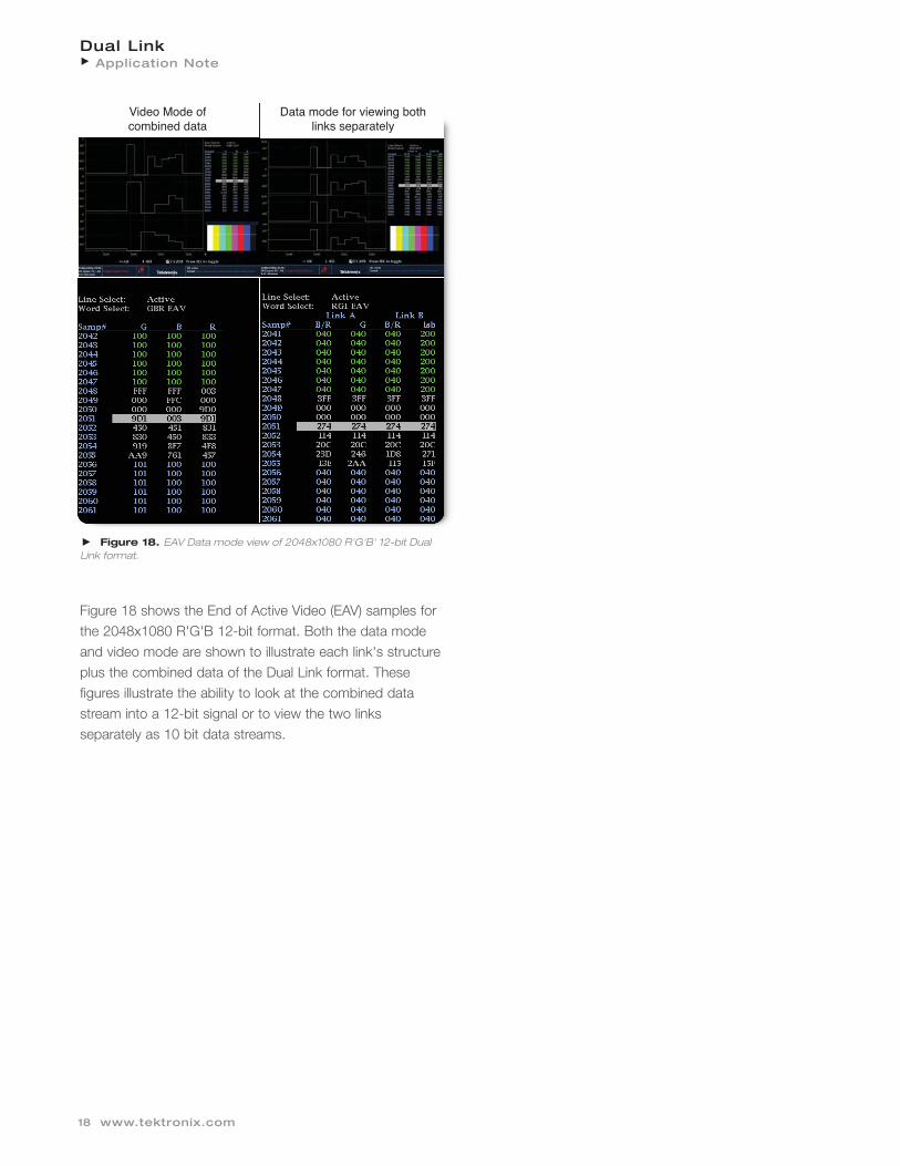
Figure 18 shows the End of Active Video (EAV) samples forthe 2048x1080 R'G'B 12-bit format. Both the data modeand video mode are shown to illustrate each link's structureplus the combined data of the Dual Link format. These figures illustrate the ability to look at the combined datastream into a 12-bit signal or to view the two links separately as 10 bit data streams.
Figure 18. EAV Data mode view of 2048x1080 R'G'B' 12-bit Dual Link format.
Video Mode of combined data
Data mode for viewing both links separately
Conclusion
The Dual Link format allows video facilities to use theirexisting HD-SDI infrastructure to carry these extended higher resolution formats. In order to carry these Dual Linkformats, it is important to ensure that inter-channel timingerrors are not introduced within the transmission path whichcould cause problems for equipment to combine the twosignals. Additional care has to be take to ensure that correct signals are applied to the device for Link A and Link B. The WFM7x20 and WVR7x20 series are useful tools to identify errors within the transmission of Dual Link signals, and for monitoring the separate or combined data streams.
For Further InformationTektronix maintains a comprehensive, constantly expanding collection ofapplication notes, technical briefs and other resources to help engineersworking on the cutting edge of technology. Please visit www.tektronix.com