52
DUALMASTER L-558/L-558 Operating Manual
DUALMASTER
L-558/L-558
Operating Manual

Blank page
Congratulations on your purchase of aSekonic DUALMASTER L-558/L-558CINE
Exposure Meter
The DUALMASTER L-558/L-558CINE is the latest addition to the extensive lineof Sekonic Exposure Meters, which have been market leaders for over 50 years.
The DUALMASTER was designed to offer more of what today’s photographerneeds, and less of what they don’t. It offers flash and ambient exposure meteringin both spot and incident modes. The DUALMASTER is the first multi-functionmeter to offer a 1-degree (nine element camera-quality) spot that measuresreflected flash output as low as f/2.0. Along with its many unique features, the L-558 is also capable of wireless flash triggering with an optional radio module.
Utilizing rubber seals throughout the housing and controls of the meter, theDualMaster is water and moisture resistant. Although the meter can be used inrainy or wet conditions, it should not be used underwater.
The large LCD panel makes reading the data easy and convenient; the panelilluminates automatically in low light surroundings.
In order to retain the simple stylish look of the DUALMASTER, less frequentlyused functions and controls are confined to custom software settings.
The DUALMASTER L-558 and L-558CINE is loaded with many features and controloptions. Since each of these features has a detailed explanation, this instructionbooklet is extensive. We recommend that you read the manual to familiarizeyourself with the potential of the meter. Once you have established which featuresand functions are important to you, refer to these sections only.
The DUALMASTER has undergone extensive quality control at every step ofmanufacture. Please read this instruction manual thoroughly, to be able to takeadvantage of its many features and to obtain the long service life that it wasdesigned to offer you.
Thank you for investing in Sekonic.
Table of Contents
1. Parts Designation ................................................................................................................ 1
2. Explanation of the Liquid Crystal Display (LCD) .................................................................. 2-4
3. Before Using ........................................................................................................................ 5-71. Attach the strap ......................................................................................................... 52. Inserting the battery ................................................................................................... 53. Checking battery capacity ......................................................................................... 54. Replacing battery during measurement
or when using the memory function .......................................................................... 65. Auto Power Off function ............................................................................................. 66. Setting main ISO film speed ...................................................................................... 67. Setting second ISO film speed (ISO 2) ..................................................................... 68. Mode and setting Lock or Lock Off ............................................................................ 7
4. Basic Operation ................................................................................................................... 8-111. Incident or reflected spot measuring ......................................................................... 82. Setting measuring mode ........................................................................................... 93. When set for incident light ......................................................................................... 104. When set for reflected light (spot metering) .............................................................. 11
5. Measurment ........................................................................................................................ 12-221. Measuring Ambient Light ........................................................................................... 12
1-1 Shutter Speed Priority mode ........................................................................... 121-2 Aperture Priority mode .................................................................................... 131-3 EV mode ......................................................................................................... 141-4 Cinematography .............................................................................................. 15
2. Measuring Flash Light ............................................................................................... 172-1 Cord Flash mode ............................................................................................. 172-2 Auto Reset Cordless Flash mode ................................................................... 182-3 Cord Multiple Flash (cumulative) mode ........................................................... 202-4 Cordless Multiple Flash (cumulative) mode .................................................... 21
6. Advanced Functions ............................................................................................................ 23-371. Memory function ........................................................................................................ 232. Averaging function ..................................................................................................... 243. Brightness Difference function ................................................................................... 244. How to use an incident Illuminance (LUX or FC) Meter ............................................ 265. How to use a reflected luminance (cd/m2 or FL) meter ............................................. 276. How to use Exposure compensation function ........................................................... 287. How to use Calibration compensation function ......................................................... 298. Filter compensation ................................................................................................... 309. Flash analyzing function ............................................................................................ 3110. Custom setting function ............................................................................................. 3211. Wireless flash radio triggering system ....................................................................... 34
7. Accessories ........................................................................................................................ 37-38
8. Technical Data ..................................................................................................................... 39-40
9. Safety Guide ........................................................................................................................ 41
10. Care and Maintenance ........................................................................................................ 42
-1-
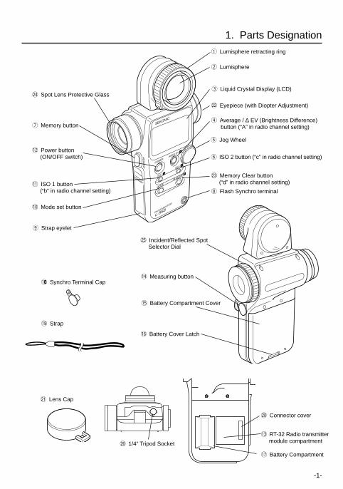
1. Parts Designation
!008 Synchro Terminal Cap
!9 Strap
i Flash Synchro terminal
w Lumisphere
@2 Eyepiece (with Diopter Adjustment)
r Average / ∆ EV (Brightness Difference) button (“A” in radio channel setting)
t Jog Wheel
y ISO 2 button (“c” in radio channel setting)
!1 ISO 1 button (“b” in radio channel setting)
!0 Mode set button
@3 Memory Clear button (“d” in radio channel setting)
u Memory button
q Lumisphere retracting ring
!4 Measuring button
!6 Battery Cover Latch
!7 Battery Compartment
@4 Spot Lens Protective Glass
!2 Power button (ON/OFF switch)
e Liquid Crystal Display (LCD)
@5 Incident/Reflected Spot Selector Dial
@6 1/4” Tripod Socket
@1 Lens Cap
o Strap eyelet
SEKONIC
MEM
OR
Y
ISO 1 b
MODE
POWER
DUALMASTER
L-558
M.CLEAR d
ISO 2 c
AVE/∆ EV A
!5 Battery Compartment Cover
@0 Connector cover
!3 RT-32 Radio transmitter module compartment
-2-
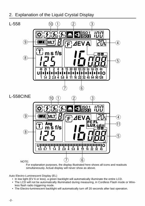
2. Explanation of the Liquid Crystal Display
Auto Electro-Luminescent Display (EL) • In low light (EV 6 or less), a green backlight will automatically illuminate the entire LCD. • The LCD will not be automatically illuminated during measuring, in Cordless Flash mode or Wire-
less flash radio triggering mode. • The Electro-luminescent backlight will automatically turn off 20 seconds after last operation.
NOTE:For explanation purposes, the display illustrated here shows all icons and readoutssimultaneously. Actual display will never show as above.
L-558
L-558CINE
o
i
!0 q w e
r
t
u
o
i
!0 q w e
r
!1
t
yu
y
In setting : iFlash analyzing : rLuminance : / (Only L-558CINE)
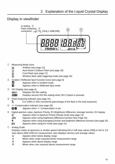
Display in viewfinder
ty
2. Explanation of the Liquid Crystal Display
q Measuring Mode IconsAmbient (see page 12)Auto-Reset Cordless Flash (see page 18)Cord Flash (see page 17)Wireless flash radio triggering mode (see page 34)
w Incident / Reflected Spot Function Icons (see page 8)Appears when in Incident modeAppears when in Reflected Spot mode
e ISO Display (see page 6)Displays ISO film settingDisplays second ISO film setting when ISO 2 button is pressed
r Flash Analyzing indicator (see page 31)0 to 100% in 10% increments (percentage of the flash in the total exposure)
t +/- Compensation Indicator (see page 28)Appears when +/- Compensation is set
y Digital aperture value, Aperture Priority, EV Brightness Difference, Average function, EV displayAppears when in Aperture Priority (f/stop) mode (see page 13)Appears when using brightness difference function (See Page 24)Appears when using Averaging function and brighness difference function (see page 24)Appears when using EV mode (see page 14)
u Analog ScaleDisplays marks at apertures or shutter speed indicating full or half stop values (558),or full or 1/3stop values (558 CINE) for measurement, also displays memory and average values Appears when below display range
Blinks when under exposed below measurement range Appears when above display range
Blinks when over exposed above measurement range
-3-
i Shutter priority indicator, shutter speed display for still photography or frames per second (f/s) forcinematography
Appears when Shutter Priority (T) mode (see page 12)Appears when shutter speed is in minutesAppears when shutter speed is in full secondsAppears when cine speed is set in frames per second (see page 15)Appears when shutter angle is set to a value other than 180 degrees (558 CINE)(seepage 16)
o Battery Power Indicator (see page 5)
!0 Memory / Multiple Flash Indicator DisplayAppears when Multi (cumulative) flash measurement mode and shows the cumulatednumber of measurements (see page 20)Appears when reading is memorized and shows the number in memory (see page 23)
!1 Illuminance mark / Luminance mark (558 CINE)Appears when Foot-Candle is selectedAppears when Lux is selectedAppears when Foot-Lambert is selectedAppears when Cd/m2 is selected
2. Explanation of the Liquid Crystal Display
-4-
-5-
Reference: • We recommend you always have a spare battery on hand.
• If the liquid crystal display extinguishes immediately after the display appears whenpower is first applied, that is an indication that the battery is dead. Please promptlyreplace the battery.
• A three second pause between power on and off is recommended to avoid damage tothe meter.
3. Before Using
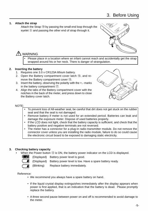
1. Attach the strapAttach the Strap !9 by passing the small end loop through theeyelet o and passing the other end of strap through it.
2. Inserting the battery 1. Requires one 3.0 v CR123A lithium battery. 2. Open the Battery compartment cover latch !6, and re-
move the Battery compartment cover !5. 3. Insert the battery, observing the polarity with the +,- marks
in the battery compartment !7. 4. Align the tabs of the Battery compartment cover with the
notches in the back of the meter, and press down to closethe Battery cover latch.
NOTE:• To prevent loss of All-weather seal, be careful that dirt does not get stuck on the rubber
seal and that the seal is not damaged.• Remove battery if meter is not used for an extended period. Batteries can leak and
damage the exposure meter. Dispose of used batteries properly.• If the LCD does not light, check that the battery capacity is sufficient, and check that the
battery positive and negative terminals are not reversed.• The meter has a connector for a plug-in radio transmitter module. Do not remove the
connector cover unless you are installing the radio module, failure to do so could causethe electronic circuit board to be exposed to damaging static electricity.
WARNING• Please place in a location where an infant cannot reach and accidentally get the strap
wrapped around his or her neck. There is danger of strangulation.
3. Checking battery capacity • When the Power button !2 is ON, the battery power indicator on the LCD is displayed.
(Displayed) Battery power level is good.
(Displayed) Battery power level is low. Have a spare battery ready.
(Blinking) Replace battery immediately.
MOODE
DUALMASTER
L-558
-6-
3. Before Using
4. Replacing battery during measurement or when using the memory function1. Always turn the power OFF before replacing batteries. If batteries are removed with the power
ON, measurements and settings in memory can no longer be recalled.
2. If after replacing the battery, or during measurements, strange screens (displays that have notbeen set) appear in the LCD, or nothing happens, no matter what button is pushed, remove thebattery and wait at least ten seconds and then replace the battery. This allows the software toautomatically reset.
WARNING:• Never place batteries in fire, short, disassemble, or heat them. The batteries might break
down, and cause an accident, injury or pollute the environment.
5. Auto Power Off function1. To conserve battery power, the meter will turn off about twenty minutes after last use.2. Whether the Auto Power Saving feature turns the power off or the Power button !2 is pressed,
the settings and measured values remain stored in memory. When the Power button is pressedagain the last settings are displayed.
Reference: • The power shuts off automatically after 1 minute when the power button is pressed and held.
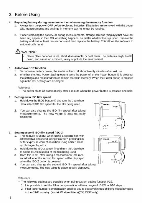
6. Setting main ISO film speed1. Hold down the ISO1 button !1 and turn the Jog wheel
t to select ISO film speed for the film being used.
2. You can also change the ISO film speed after takingmeasurements. The new value is automaticallydisplayed.
7. Setting second ISO film speed (ISO 2)1. This feature is useful when using a second film with
different ISO film speed, using PolaroidTM proofing film,or for exposure correction (when using a filter, close-up photography, etc.).
2. Hold down the ISO 2 button y and turn the Jog wheelto select ISO film speed of the film being used.
3. Once this is set, after taking a measurement, the mea-sured value for the second film speed will be displayedwhen the ISO 2 button is pressed.
4. You can also change the second ISO film speed after takingmeasurements. The new value is automatically displayed.
Reference: • The following settings are possible when using custom setting function P32.
1. It is possible to set the Filter compensation within a range of ±5 EV in 1/10 steps.2. Filter factor number compensation enables you to set seven types of filters frequently used
in the CINE industry. (Kodak Wratten Filters)(558 CINE only)
ISO 1 b
ISO 2 c
-7-
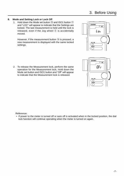
8. Mode and Setting Lock or Lock Off 1. Hold down the Mode set button !0 and ISO1 button !1
and “LOC” will appear to indicate that the Settings arelocked. The last measurement is held until the lock isreleased, even if the Jog wheel t is accidentallymoved.
However, if the measurement button !4 is pressed, anew measurement is displayed with the same lockedsettings.
2. To release the Measurement lock, perform the sameoperation for the Measurement lock, Hold down theMode set button and ISO1 button and “Off” will appearto indicate that the Measurement lock is released.
Reference: • If power to the meter is turned off or auto off is activated when in the locked position, the dial
lock function will continue operating when the meter is turned on again.
3. Before Using
ISO 1 b
MODE
ISO 1 b
MODE
-8-
4. Basic Operation
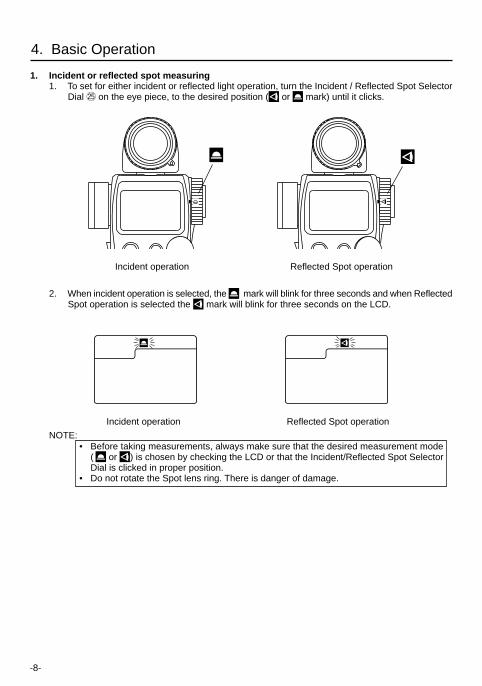
1. Incident or reflected spot measuring1. To set for either incident or reflected light operation, turn the Incident / Reflected Spot Selector
Dial @5 on the eye piece, to the desired position ( or mark) until it clicks.
2. When incident operation is selected, the mark will blink for three seconds and when ReflectedSpot operation is selected the mark will blink for three seconds on the LCD.
NOTE:• Before taking measurements, always make sure that the desired measurement mode
( or ) is chosen by checking the LCD or that the Incident/Reflected Spot SelectorDial is clicked in proper position.
• Do not rotate the Spot lens ring. There is danger of damage.
Incident operation Reflected Spot operation
Incident operation Reflected Spot operation
-9-
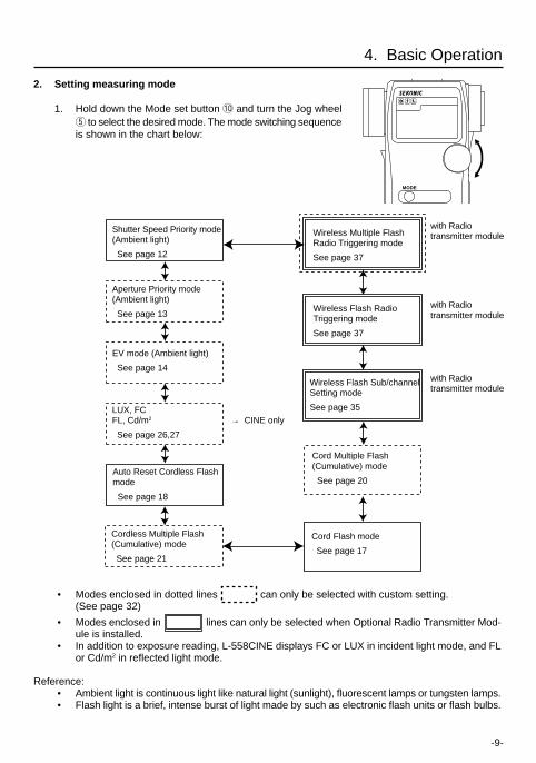
2. Setting measuring mode
1. Hold down the Mode set button !0 and turn the Jog wheelt to select the desired mode. The mode switching sequenceis shown in the chart below:
• Modes enclosed in dotted lines can only be selected with custom setting.(See page 32)
• Modes enclosed in lines can only be selected when Optional Radio Transmitter Mod-ule is installed.
• In addition to exposure reading, L-558CINE displays FC or LUX in incident light mode, and FLor Cd/m2 in reflected light mode.
Reference: • Ambient light is continuous light like natural light (sunlight), fluorescent lamps or tungsten lamps. • Flash light is a brief, intense burst of light made by such as electronic flash units or flash bulbs.
4. Basic Operation
Wireless Multiple FlashRadio Triggering mode
See page 37
Wireless Flash RadioTriggering mode
See page 37
Wireless Flash Sub/channelSetting mode
See page 35
Shutter Speed Priority mode(Ambient light)
See page 12
Aperture Priority mode(Ambient light)
See page 13
EV mode (Ambient light)
See page 14
LUX, FCFL, Cd/m2
See page 26,27
Cord Multiple Flash(Cumulative) mode
See page 20
with Radiotransmitter module
Auto Reset Cordless Flashmode
See page 18
Cord Flash mode
See page 17
MODE
Cordless Multiple Flash(Cumulative) mode
See page 21
with Radiotransmitter module
with Radiotransmitter module
→ CINE only
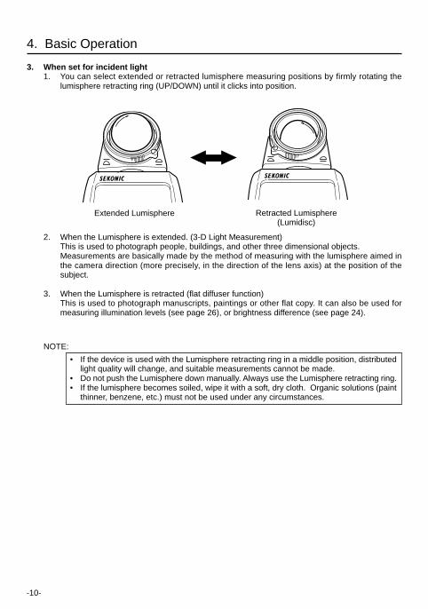
Extended Lumisphere
Retracted Lumisphere
( L u m i d i s c )
-11-
4. Basic Operation
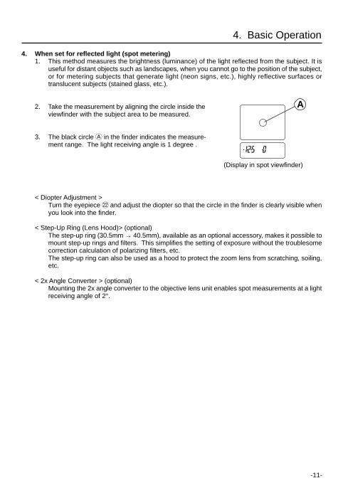
4. When set for reflected light (spot metering)1. This method measures the brightness (luminance) of the light reflected from the subject. It is
useful for distant objects such as landscapes, when you cannot go to the position of the subject,or for metering subjects that generate light (neon signs, etc.), highly reflective surfaces ortranslucent subjects (stained glass, etc.).
2. Take the measurement by aligning the circle inside theviewfinder with the subject area to be measured.
3. The black circle A in the finder indicates the measure-ment range. The light receiving angle is 1 degree .
< Diopter Adjustment >Turn the eyepiece @2 and adjust the diopter so that the circle in the finder is clearly visible whenyou look into the finder.
< Step-Up Ring (Lens Hood)> (optional)The step-up ring (30.5mm → 40.5mm), available as an optional accessory, makes it possible tomount step-up rings and filters. This simplifies the setting of exposure without the troublesomecorrection calculation of polarizing filters, etc. (see page 37)The step-up ring can also be used as a hood to protect the zoom lens from scratching, soiling,etc.
< 2x Angle Converter > (optional)Mounting the 2x angle converter to the objective lens unit enables spot measurements at a lightreceiving angle of 2°.
A
(Display in spot viewfinder)
-12-
5. Measurement
1. Measuring ambient lightIn this measurement mode, we have the choice of shutter priority mode, aperture priority mode andEV mode. Hold down the Mode set button !0 and turn the Jog wheel t to select ambient measurementmode .
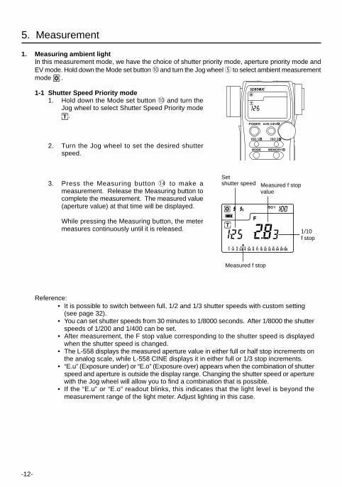
1-1 Shutter Speed Priority mode1. Hold down the Mode set button !0 and turn the
Jog wheel to select Shutter Speed Priority mode.
2. Turn the Jog wheel to set the desired shutterspeed.
3. Press the Measuring button !4 to make ameasurement. Release the Measuring button tocomplete the measurement. The measured value(aperture value) at that time will be displayed.
While pressing the Measuring button, the metermeasures continuously until it is released.
Reference: • It is possible to switch between full, 1/2 and 1/3 shutter speeds with custom setting
(see page 32). • You can set shutter speeds from 30 minutes to 1/8000 seconds. After 1/8000 the shutter
speeds of 1/200 and 1/400 can be set. • After measurement, the F stop value corresponding to the shutter speed is displayed
when the shutter speed is changed. • The L-558 displays the measured aperture value in either full or half stop increments on
the analog scale, while L-558 CINE displays it in either full or 1/3 stop increments. • “E.u” (Exposure under) or “E.o” (Exposure over) appears when the combination of shutter
speed and aperture is outside the display range. Changing the shutter speed or aperturewith the Jog wheel will allow you to find a combination that is possible.
• If the “E.u” or “E.o” readout blinks, this indicates that the light level is beyond themeasurement range of the light meter. Adjust lighting in this case.
Measured f stopvalue
1/10f stop
Setshutter speed
Measured f stop
POWER
ISO 1 b
MODE
ISO 2 c
AVE./∆EV A
MEMORY d
-13-
1-2 Aperture Priority mode
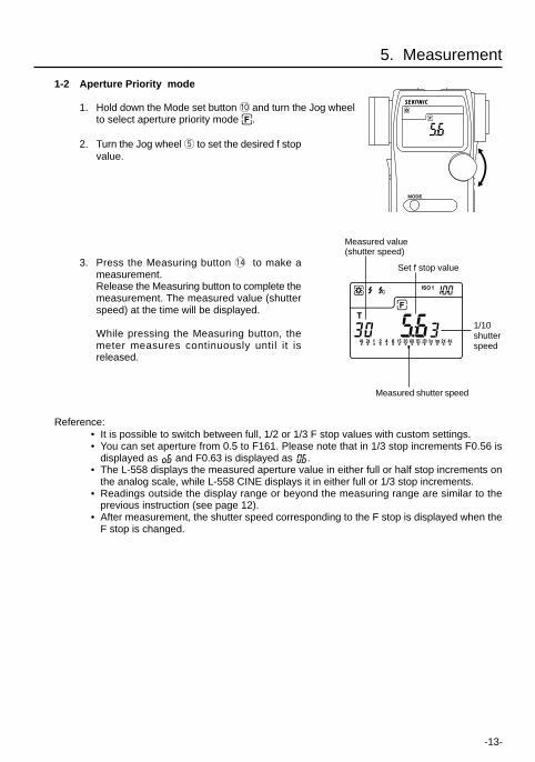
1. Hold down the Mode set button !0 and turn the Jog wheelto select aperture priority mode .
2. Turn the Jog wheel t to set the desired f stopvalue.
3. Press the Measuring button !4 to make ameasurement.Release the Measuring button to complete themeasurement. The measured value (shutterspeed) at the time will be displayed.
While pressing the Measuring button, themeter measures continuously until it isreleased.
Reference: • It is possible to switch between full, 1/2 or 1/3 F stop values with custom settings. • You can set aperture from 0.5 to F161. Please note that in 1/3 stop increments F0.56 is
displayed as and F0.63 is displayed as . • The L-558 displays the measured aperture value in either full or half stop increments on
the analog scale, while L-558 CINE displays it in either full or 1/3 stop increments. • Readings outside the display range or beyond the measuring range are similar to the
previous instruction (see page 12). • After measurement, the shutter speed corresponding to the F stop is displayed when the
F stop is changed.
5. Measurement
1/10shutterspeed
Set f stop value
Measured value(shutter speed)
MODE
Measured shutter speed
-14-
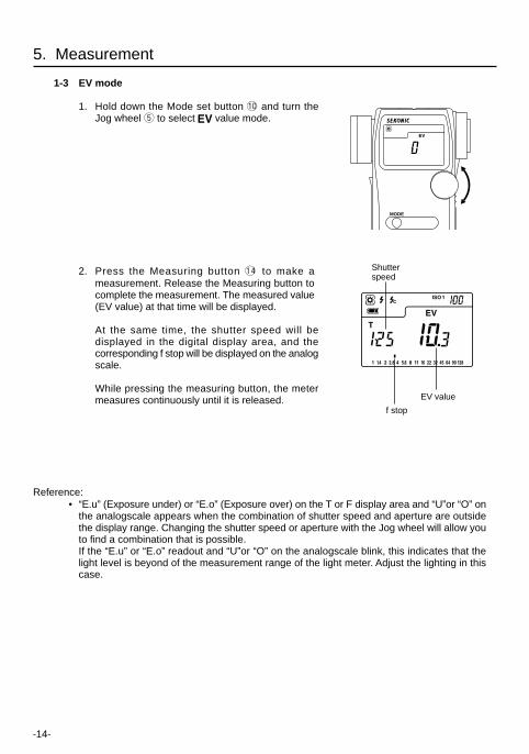
1-3 EV mode
1. Hold down the Mode set button !0 and turn theJog wheel t to select value mode.
2. Press the Measuring button !4 to make ameasurement. Release the Measuring button tocomplete the measurement. The measured value(EV value) at that time will be displayed.
At the same time, the shutter speed will bedisplayed in the digital display area, and thecorresponding f stop will be displayed on the analogscale.
While pressing the measuring button, the metermeasures continuously until it is released.
Reference: • “E.u” (Exposure under) or “E.o” (Exposure over) on the T or F display area and “U”or “O” on
the analogscale appears when the combination of shutter speed and aperture are outsidethe display range. Changing the shutter speed or aperture with the Jog wheel will allow youto find a combination that is possible.If the “E.u” or “E.o” readout and “U”or “O” on the analogscale blink, this indicates that thelight level is beyond of the measurement range of the light meter. Adjust the lighting in thiscase.
f stop
Shutterspeed
EV value
5. Measurement
MODE
-15-
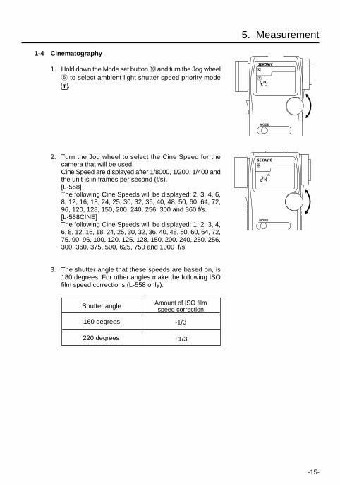
1-4 Cinematography
1. Hold down the Mode set button !0 and turn the Jog wheelt to select ambient light shutter speed priority mode
.
2. Turn the Jog wheel to select the Cine Speed for thecamera that will be used.Cine Speed are displayed after 1/8000, 1/200, 1/400 andthe unit is in frames per second (f/s).[L-558]The following Cine Speeds will be displayed: 2, 3, 4, 6,8, 12, 16, 18, 24, 25, 30, 32, 36, 40, 48, 50, 60, 64, 72,96, 120, 128, 150, 200, 240, 256, 300 and 360 f/s.[L-558CINE]The following Cine Speeds will be displayed: 1, 2, 3, 4,6, 8, 12, 16, 18, 24, 25, 30, 32, 36, 40, 48, 50, 60, 64, 72,75, 90, 96, 100, 120, 125, 128, 150, 200, 240, 250, 256,300, 360, 375, 500, 625, 750 and 1000 f/s.
3. The shutter angle that these speeds are based on, is180 degrees. For other angles make the following ISOfilm speed corrections (L-558 only).
5. Measurement
Shutter angle Amount of ISO filmspeed correction
160 degrees -1/3
220 degrees +1/3
MODE
MODE
-16-
* Example of correction value-1/3: Decrease ISO film speed by 1/3 stop, example: ISO 80 -1/3 stop = ISO 64+1/3: Increase ISO film speed by 1/3 stop, example: ISO 80 +1/3 stop = ISO 100
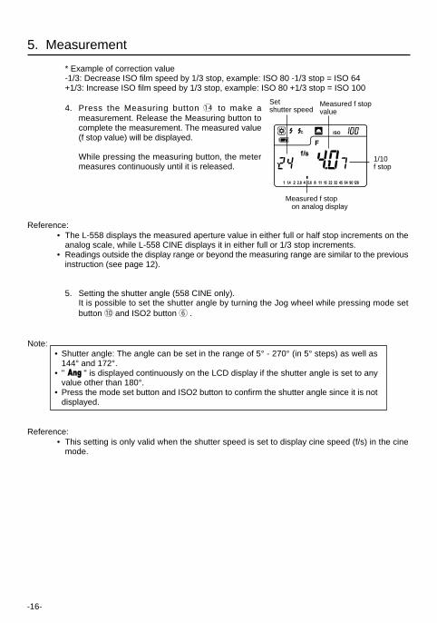
4. Press the Measuring button !4 to make ameasurement. Release the Measuring button tocomplete the measurement. The measured value(f stop value) will be displayed.
While pressing the measuring button, the metermeasures continuously until it is released.
Reference: • The L-558 displays the measured aperture value in either full or half stop increments on the
analog scale, while L-558 CINE displays it in either full or 1/3 stop increments. • Readings outside the display range or beyond the measuring range are similar to the previous
instruction (see page 12).
5. Setting the shutter angle (558 CINE only).It is possible to set the shutter angle by turning the Jog wheel while pressing mode setbutton !0 and ISO2 button y .
Note:• Shutter angle: The angle can be set in the range of 5° - 270° (in 5° steps) as well as
144° and 172°.• " " is displayed continuously on the LCD display if the shutter angle is set to any
value other than 180°.• Press the mode set button and ISO2 button to confirm the shutter angle since it is not
displayed.
Reference: • This setting is only valid when the shutter speed is set to display cine speed (f/s) in the cine
mode.
Setshutter speed
Measured f stop on analog display
Measured f stopvalue
5. Measurement
1/10f stop
-17-
2. Measuring flash lightThis method of measurement can be done in the following modes; with cord, without cord, multipleflash with cord, multiple flash without cord and Wireless flash radio triggering mode (with optionalradio transmitter module). When Measuring flash light, the shutter speed and F stop value (valuecombining ambient light and flash light: total amount of light) are displayed. The ambient light andflash light are each displayed as separate values together with the total amount of light on theanalog scale. In addition, the ratio of flash light to the total amount of light is displayed at that time asa value in 10% steps.The flash reading is displayed as a blinking mark above the analog scale. (Seepage 32 for details)
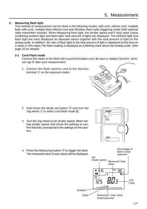
2-1 Cord Flash modeConnect the meter to the flash with a synchronization cord. Be sure to replace Synchro termi-nal cap @0 after your measurement.
1. Connect the flash synchro cord to the Synchroterminal i on the exposure meter.
2. Hold down the Mode set button !0 and turn theJog wheel t to select cord flash mode .
3. Turn the Jog wheel to set shutter speed. When set-ting shutter speed, first check the settings to con-firm that they correspond to the settings on the cam-era.
4. Press the Measuring button !4 to trigger the flash.The measured value (f stop value) will be displayed.
5. Measurement
Measured f stopvalue
1/10f stop
Setshutter speed
Measured f stop value(total exposure)
MODE
POWER
AVE./∆EV A
ISO 1 b
MOODE
DUALMASTER
L-558
MEMORY dISO 2 c
Percentage offlash in totalexposure
Flash
Ambient
-18-
Reference: • It is possible to switch the shutter speed between full, 1/2 and 1/3 stops by custom setting
(refer to P32). • The shutter speed can be set from 30 minutes to 1/1000 of a second. After 1/1000 sec, the
meter can be set at the following intermediate speeds: 1/75, 1/80,1/90, 1/100, 1/200, or1/400.
• If the film speed is changed after the measurement is taken, the new converted measuredvalue (f stop value) will be displayed.
• After measurement, the F stop value corresponding to the shutter speed is displayedwhen the shutter speed is changed.
• “E.u” (Exposure under) or “E.o” (Exposure over) appears when the combination of shutterspeed and aperture are outside the display range. Change the shutter speed with the Jogwheel and take measurements again.
• If the “E.u” or “E.o” readout blinks, this indicates that the light level is beyond themeasurement range of the light meter.
5. Measurement
CAUTION:
• There is danger of electric shock if the meter is handled with wet hands, during rain, inareas splashed by water or where there is a lot of moisture, if you use cord synchronizedflash.
• Under such conditions, it is recommended that you use the meter in the cordless flashmode or Wireless flash radio triggering mode, and keep the Synchro terminal cap inplace.
NOTE:
• The electronic flash unit may trigger when you connect the Synchro cord or operate thePOWER Switch.
• Triggering voltage is 2.0 to 400 volts. Below 2.0V, trigger flash with the cordless flashmode or wireless flash radio triggering mode, not with synchro cord.
2-2 Auto-reset cordless flash modeMeasurements are made by the meter receiving the light from the flash. This measurementmode is used when the Synchro cord will not reach because of the distance between the flashand meter or when use of the Synchro cord is inconvenient.
1. Hold down the Mode set button !0 and turn theJog wheel t to set Auto-reset Cordless Flashmode .
2. Turn the Jog wheel to set shutter speed. Whensetting shutter speed, first check the settings toconfirm that they correspond to the settingsavailable on the camera.
MODE
WARNING• Please place in a location where an infant cannot reach and accidentally swallow the
synchro terminal cap. There is danger of strangulation.
-19-
NOTES:
• When firing a flash, if the flash brightness is low compared to the ambient light, the metermay fail to detect the light. In this case, make measurements using the cord flash mode.
• Rapid start fluorescent lamps and special lighting are sometimes mistaken for flash, andaccidentally measured. In this case, make measurements using the cord flash mode.
• The meter’s tripod socket permits mounting it to a tripod or light stand and placing itstrategically when using cordless flash mode.
Reference: • After measurement, the F stop value corresponding to the shutter speed is displayed when
the shutter speed is changed. • Setting the shutter speed is similar to the previous instruction. (see page 17) of “Cord flash
mode” of section 2-1. • A new converted value is displayed when the film speed is changed after taking the
measurement. • Readings outside the display range or beyond the measuring range are similar to the previous
instruction. (see page 18) of “Cord Flash mode” of section 2-1.
5. Measurement
Measured f stopvalue
1/10f stop
Measured f stop(total exposure)
Set shutter speed
3. When the Measuring button !4 is pressed, themode mark will blink and the meter is ready tomeasure. The ready to measure mode will continuefor approximately 90 seconds.During this time, trigger the flash to make ameasurement.
4. If the 90 second period is exceeded and the blinkingmark stops, press the Measuring button again toreturn to ready to measure.
5. When the light from the flash is received, themeasured value (f stop) is displayed. Even aftermeasurement, the mode mark continues to blinkand the meter is in ready state and a newmeasurement can be made. (Auto-reset function)
Perecentage offlash in totalexposure
Flash
Ambient
-20-
2-3 Cord multiple flash (cumulative) modeThese measurements are used when the light generated by the flash is inadequate for properexposure. The repeated flash pops can be accumulated until the desired aperture is displayed.The cumulative number is infinite. Only one digit is displayed if the cumulative number is ten ormore. Display returns 0 (0=10, 1=11, 2=12, etc.)
1. Hold down the Mode set button !0 and turn theJog wheel t to select cord multiple flash (cumu-lative) mode .
2. Turn the Jog wheel t to set shutter speed. When setting shutter speed, first check thesettings to confirm that they correspond to the settings available on the camera.
3. Connect the Flash synchro cord to the meter'ssynchro terminal i.
4. Press the Measuring button !4 to trigger a flash. The measured f stop value at that time willbe displayed. Each time this is repeated, the accumulated f stop value and the number ofcumulative flashes is displayed.
5. To clear the cumulative value, press M. CLEAR button @3 or switch to another mode byturning the Jog wheel while pressing the mode set button.
5. Measurement
Measured f stop(total exposure)
1/10 f stopNumber ofcumulative flashes
Setshutter speed
Perecentage of flashin total exposure
MODE
1st. time 2nd. time 3rd. time
-21-
MODE
NOTE:
• The flash unit may flash when you connect the synchro cord or operate the POWER switch.• When firing a flash to take measurements, check the camera's synchronizing range and
set the proper shutter speed.• For flash units with low electric trigger voltage, the flash may not fire. In this case, make
measurements in cordless flash mode or wireless flash radio triggering mode.
Reference: • Setting the shutter speed is similar to the previous instruction (see page 17). • Readings outside the display range or beyond the measuring range, are similar to the previous
instruction (see page 18) of “Cord flash mode” of section 2-1. • If the film speed is changed after the measurement is taken, the new converted measured
value (f stop value) will be displayed.
CAUTION:
• There is danger of electric shock if the meter is handled with wet hands, during rain, inareas splashed by water or where there is a lot of moisture.Under such conditions, it is recommended that you use the meter in the cordless flashmode, or wireless flash radio triggering mode and keep the Synchro terminal cap in place.
5. Measurement
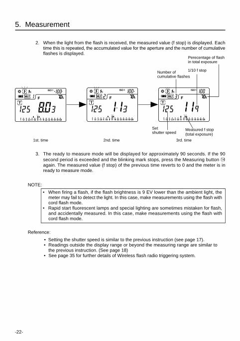
2-4 Cordless multiple flash (cumulative) modeThese measurements are used when the light generated by the flash is inadequate for properexposure. The repeated flash pops can be accumulated until the desired aperture is displayed.The cumulative number is infinite. Only one digit is displayed if the cumulative number is ten ormore. Display returns 0 (0=10, 1=11, 2=12 etc.)
1. Hold down the Mode set button !0 and turn theJog wheel t to select flash measurement cordlessmultiple flash (cumulative) mode .Turn the Jog wheel to set shutter speed. Whensetting shutter speed, first check the settings toconfirm that they correspond to the settingsavailable on the camera.
-22-
5. Measurement
1/10 f stopNumber ofcumulative flashes
Setshutter speed
2. When the light from the flash is received, the measured value (f stop) is displayed. Eachtime this is repeated, the accumulated value for the aperture and the number of cumulativeflashes is displayed.
3. The ready to measure mode will be displayed for approximately 90 seconds. If the 90second period is exceeded and the blinking mark stops, press the Measuring button !4again. The measured value (f stop) of the previous time reverts to 0 and the meter is inready to measure mode.
NOTE:
• When firing a flash, if the flash brightness is 9 EV lower than the ambient light, themeter may fail to detect the light. In this case, make measurements using the flash withcord flash mode.
• Rapid start fluorescent lamps and special lighting are sometimes mistaken for flash,and accidentally measured. In this case, make measurements using the flash withcord flash mode.
Reference:
• Setting the shutter speed is similar to the previous instruction (see page 17). • Readings outside the display range or beyond the measuring range are similar to
the previous instruction. (See page 18) • See page 35 for further details of Wireless flash radio triggering system.
Measured f stop(total exposure)
Perecentage of flashin total exposure
1st. time 2nd. time 3rd. time
-23-
6. Advanced Functions
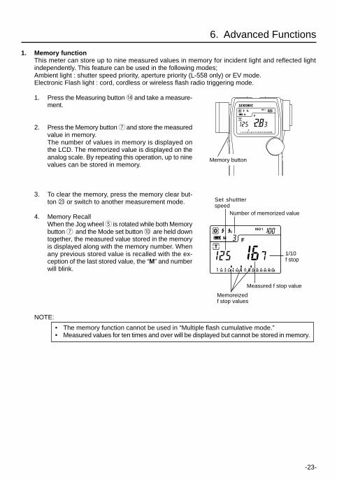
1. Memory functionThis meter can store up to nine measured values in memory for incident light and reflected lightindependently. This feature can be used in the following modes;Ambient light : shutter speed priority, aperture priority (L-558 only) or EV mode.Electronic Flash light : cord, cordless or wireless flash radio triggering mode.
1. Press the Measuring button !4 and take a measure-ment.
2. Press the Memory button u and store the measuredvalue in memory.The number of values in memory is displayed onthe LCD. The memorized value is displayed on theanalog scale. By repeating this operation, up to ninevalues can be stored in memory.
3. To clear the memory, press the memory clear but-ton @3 or switch to another measurement mode.
4. Memory RecallWhen the Jog wheel t is rotated while both Memorybutton u and the Mode set button !0 are held downtogether, the measured value stored in the memoryis displayed along with the memory number. Whenany previous stored value is recalled with the ex-ception of the last stored value, the “M” and numberwill blink.
NOTE:
• The memory function cannot be used in “Multiple flash cumulative mode.”• Measured values for ten times and over will be displayed but cannot be stored in memory.
1/10f stop
Measured f stop value
Memoreizedf stop values
Set shuttterspeed
Number of memorized value
Memory button
-24-
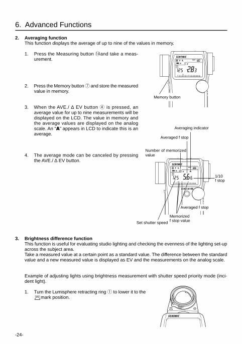
2. Averaging functionThis function displays the average of up to nine of the values in memory.
1. Press the Measuring button !4and take a meas-urement.
2. Press the Memory button u and store the measuredvalue in memory.
3. When the AVE./ ∆ EV button r is pressed, anaverage value for up to nine measurements will bedisplayed on the LCD. The value in memory andthe average values are displayed on the analogscale. An “A” appears in LCD to indicate this is anaverage.
4. The average mode can be canceled by pressingthe AVE./ ∆ EV button.
6. Advanced Functions
AVE./∆EV A
Memorizedf stop valueSet shutter speed
Averaging indicator
Number of memorizedvalue
Averaged f stop
1/10f stop
Averaged f stop
3. Brightness difference functionThis function is useful for evaluating studio lighting and checking the evenness of the lighting set-upacross the subject area.Take a measured value at a certain point as a standard value. The difference between the standardvalue and a new measured value is displayed as EV and the measurements on the analog scale.
Example of adjusting lights using brightness measurement with shutter speed priority mode (inci-dent light).
1. Turn the Lumisphere retracting ring q to lower it to themark position.
Memory button
-25-
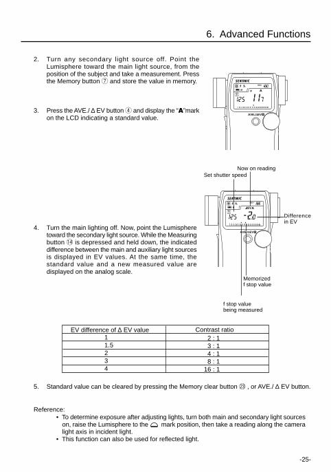
2. Turn any secondary light source off. Point theLumisphere toward the main light source, from theposition of the subject and take a measurement. Pressthe Memory button u and store the value in memory.
3. Press the AVE./ ∆ EV button r and display the “A”markon the LCD indicating a standard value.
4. Turn the main lighting off. Now, point the Lumispheretoward the secondary light source. While the Measuringbutton !4 is depressed and held down, the indicateddifference between the main and auxiliary light sourcesis displayed in EV values. At the same time, thestandard value and a new measured value aredisplayed on the analog scale.
5. Standard value can be cleared by pressing the Memory clear button @3 , or AVE./ ∆ EV button.
Reference: • To determine exposure after adjusting lights, turn both main and secondary light sources
on, raise the Lumisphere to the mark position, then take a reading along the cameralight axis in incident light.
• This function can also be used for reflected light.
2 : 13 : 14 : 18 : 1
16 : 1
EV difference of ∆ EV value Contrast ratio11.5234
6. Advanced Functions
Memorizedf stop value
Set shutter speed
Differencein EV
f stop valuebeing measured
Now on reading
AVE./∆EV A
AVE./∆EV A
-26-
6. Advanced Functions
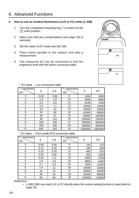
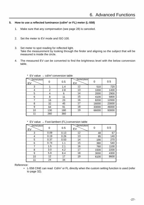
4. How to use an incident illuminance (LUX or FC) meter (L-558)
1. Turn the Lumisphere retracting ring q to lower it to the mark position.
2. Make sure that any compensation (see page 28) iscanceled.
3. Set the meter to EV mode and ISO 100.
4. Place meter parallel to the subject and take ameasurement.
5. The measured EV can be converted to find thebrightness level with the below conversion table.
* EV value → Foot candle (FC) conversion table
-2-1012345678
0.060.120.230.460.931.93.77.4153059
0.080.160.330.661.32.65.311214284
910111213141516171819
120240480950
190038007600
150003000061000
120000
170340670
130027005400
11000220004300086000
170000
EV 0 0.50 0.5Decimal places
EVDecimal places
Reference:• L-558 CINE can read LUX or FC directly when the custom setting function is used (refer to
page 32).
* EV value → Lux conversion table
-2-1012345678
0.631.32.55.010204080160320640
0.881.83.57.1142857110230450910
910111213141516171819
180036007200
140002900058000
120000230000460000930000
1900000
EVEVDecimal places
0 0.50 0.5Decimal places
130026005100
10000200004100082000
160000330000660000
1300000
-28-
6. Advanced Functions
NOTE:• Make compensation after a sufficient number of tests in actual photographic conditions
have been made to suit your needs.• Compensation effects every mode of the meter.
If recalibration has been made for specific purpose do not forget to return to originalzero settings.
Reference:• When compensation is activate, a plus ( ) or minus ( ) sign as well as the amount of
compensation is displayed continuously on the LCD display.• You can set custom settings so that a plus ( ) or minus ( ) sign as well as the amount
of compensation doesn’t appear on the LCD. (See page 32)
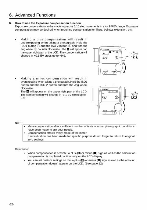
6. How to use the Exposure compensation functionExposure compensation can be made in precise 1/10 step increments in a +/- 9.9 EV range. Exposurecompensation may be desired when requiring compensation for filters, bellows extension, etc.
• Making a p lus compensat ion wi l l resul t inunderexposing when taking a photograph. Hold theISO1 button !1 and the ISO 2 button y and turn theJog wheel t counter clockwise. The will appear onthe upper right part of the LCD. The compensation willchange in +0.1 EV steps up to +9.9.
• Making a minus compensation wil l result inoverexposing when taking a photograph, Hold the ISO1button and the ISO 2 button and turn the Jog wheelclockwise.The will appear on the upper right part of the LCD.The compensation will change in -0.1 EV steps up to -9.9.
ISO 1 b ISO 2 c
ISO 1 b ISO 2 c
-29-
6. Advanced Functions
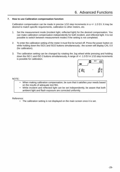
7. How to use Calibration compensation function
Calibration compensation can be made in precise 1/10 step increments in a +/- 1.0 EV. It may bedesired to match specific requirements, calibration to other meters, etc.
1. Set the measurement mode (incident light, reflected light) for the desired compensation. Youcan make calibration compensation independently for both incident, and reflected light. It is notpossible to switch between measurement modes if the setting is not completed.
2. To enter the calibration setting of the meter it must first be turned off. Press the power button onwhile holding down the ISO1 and ISO2 buttons simultaneously ; the screen will display CAL 0.0(for calibration).
3. The calibration setting can be changed by rotating the Jog wheel while pressing and holdingdown the ISO 1 and ISO 2 buttons simultaneously. A range of +/- 1.0 EV in 1/10 step incrementsis possible for calibration.
NOTE:
• When making calibration compensation, be sure that it satisfies your needs basedon the results of adequate test film.
• While incident and reflected light can be set independently, be aware that bothambient light and flash exposure are corrected uniformly.
Reference:• The calibration setting is not displayed on the main screen once it is set.
-30-
6. Advanced Functions
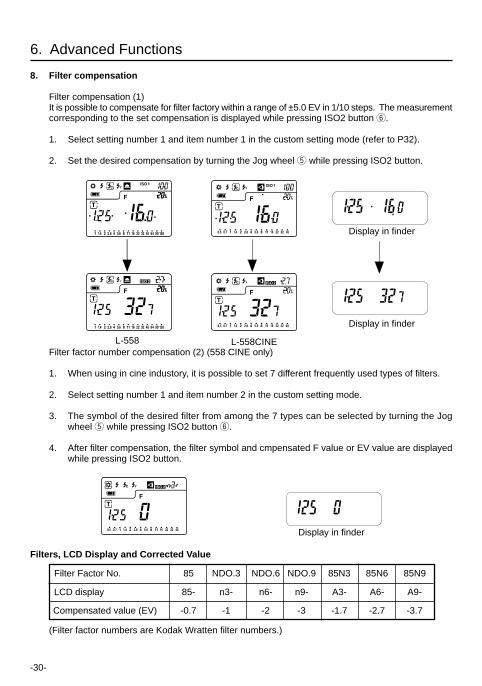
8. Filter compensation
Filter compensation (1)It is possible to compensate for filter factory within a range of ±5.0 EV in 1/10 steps. The measurementcorresponding to the set compensation is displayed while pressing ISO2 button y.
1. Select setting number 1 and item number 1 in the custom setting mode (refer to P32).
2. Set the desired compensation by turning the Jog wheel t while pressing ISO2 button.
Filter factor number compensation (2) (558 CINE only)
1. When using in cine industory, it is possible to set 7 different frequently used types of filters.
2. Select setting number 1 and item number 2 in the custom setting mode.
3. The symbol of the desired filter from among the 7 types can be selected by turning the Jogwheel t while pressing ISO2 button y.
4. After filter compensation, the filter symbol and cmpensated F value or EV value are displayedwhile pressing ISO2 button.
Filters, LCD Display and Corrected Value
Filter Factor No. 85 NDO.3 NDO.6 NDO.9 85N3 85N6 85N9
LCD display 85- n3- n6- n9- A3- A6- A9-
Compensated value (EV) -0.7 -1 -2 -3 -1.7 -2.7 -3.7
(Filter factor numbers are Kodak Wratten filter numbers.)
Display in finder
Display in finder
L-558 L-558CINE
Display in finder
-31-
6. Advanced Functions
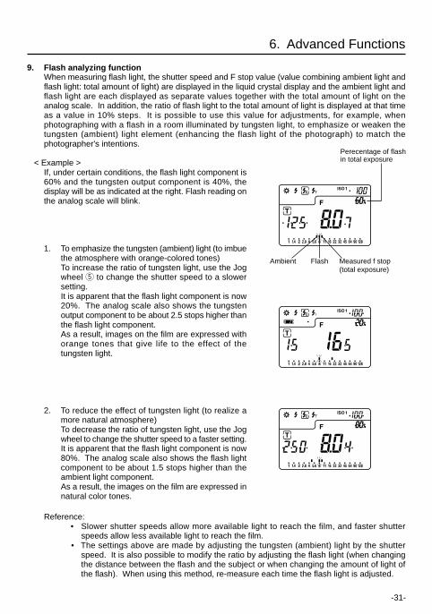
9. Flash analyzing functionWhen measuring flash light, the shutter speed and F stop value (value combining ambient light andflash light: total amount of light) are displayed in the liquid crystal display and the ambient light andflash light are each displayed as separate values together with the total amount of light on theanalog scale. In addition, the ratio of flash light to the total amount of light is displayed at that timeas a value in 10% steps. It is possible to use this value for adjustments, for example, whenphotographing with a flash in a room illuminated by tungsten light, to emphasize or weaken thetungsten (ambient) light element (enhancing the flash light of the photograph) to match thephotographer's intentions.
< Example >If, under certain conditions, the flash light component is60% and the tungsten output component is 40%, thedisplay will be as indicated at the right. Flash reading onthe analog scale will blink.
1. To emphasize the tungsten (ambient) light (to imbuethe atmosphere with orange-colored tones)To increase the ratio of tungsten light, use the Jogwheel t to change the shutter speed to a slowersetting.It is apparent that the flash light component is now20%. The analog scale also shows the tungstenoutput component to be about 2.5 stops higher thanthe flash light component.As a result, images on the film are expressed withorange tones that give life to the effect of thetungsten light.
2. To reduce the effect of tungsten light (to realize amore natural atmosphere)To decrease the ratio of tungsten light, use the Jogwheel to change the shutter speed to a faster setting.It is apparent that the flash light component is now80%. The analog scale also shows the flash lightcomponent to be about 1.5 stops higher than theambient light component.As a result, the images on the film are expressed innatural color tones.
Reference:• Slower shutter speeds allow more available light to reach the film, and faster shutter
speeds allow less available light to reach the film.• The settings above are made by adjusting the tungsten (ambient) light by the shutter
speed. It is also possible to modify the ratio by adjusting the flash light (when changingthe distance between the flash and the subject or when changing the amount of light ofthe flash). When using this method, re-measure each time the flash light is adjusted.
Measured f stop(total exposure)
Perecentage of flashin total exposure
FlashAmbient
-32-
*1 1/10 stop fractions are displayed in full, 1/2 and 1/3 step increments.
*2 Individual: LUX, FC, cd/m2 or FL
Compound: LUX+T+F, FC+T+F, cd/m2+T+F or FL+T+F (combination)
6. Advanced Functions
10. Custom setting functionIt is possible to set the required functions in advance.
FilmSensitivity1/3 step
FilmSensitivity1/3 step
Alwaysdisplay
full stop
Available
Available
Available
Compound +Individual
Not Available
Not Available
CUSTOM SETTING LIST
No.
1
2
3*1
4
5
6
7*2
8
9
Model
558
CINE
558&CINE
558&CINE
558&CINE
558&CINE
558&CINE
CINE
CINE
CINE
Lighting
Ambient &Flash
Ambient &Flash
Ambient &Flash
Ambient
Ambient
Flash
Ambient
Ambient
Ambient
Custom Setting name
ISO 2 setting
Exposure CompensationDisplay setting
Increments of reading
Aperture (F) priority mode
EV mode
Multiple flash mode(cumulative)
Illuminance or Luminance(CINE only) display
Illuminance measurementin Incident mode
Luminance measurementin Reflected mode
Item
Filtercompensation
(1)0.1EV step
(±5EV)
Filtercompensation
(1)0.1EV step
(±5EV)
Notdisplay
1/3 stop
NotAvailable
NotAvailable
NotAvailable
Compound
LUX
cd/m2
—
Filtercompensation(2) 7 Filter
factornumbers
—
1/2 stop
—
—
—
Individual
FC
FL
—
—
—
—
—
—
—
—
LUX, FC
cd/m2,FL
0 1 2 3
Reference:• L-558 - Default settings are all set to zero (0).• L-558 (CINE) - Default settings are all set to zero (0) except for item numbers 8 and 9
which are set to setting three (3).
-33-
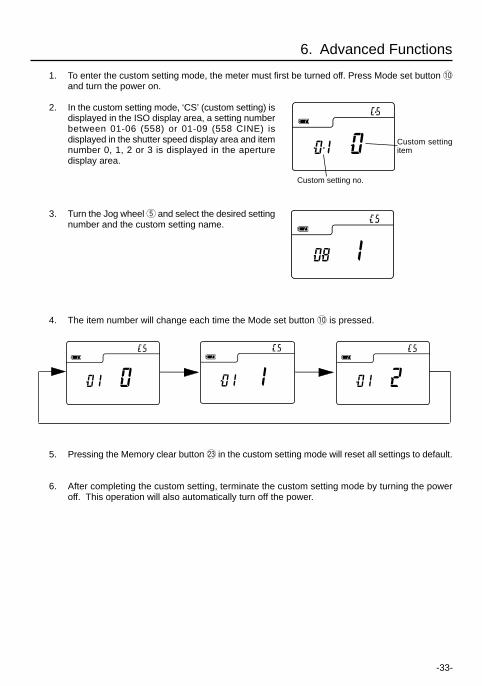
1. To enter the custom setting mode, the meter must first be turned off. Press Mode set button !0and turn the power on.
2. In the custom setting mode, ‘CS’ (custom setting) isdisplayed in the ISO display area, a setting numberbetween 01-06 (558) or 01-09 (558 CINE) isdisplayed in the shutter speed display area and itemnumber 0, 1, 2 or 3 is displayed in the aperturedisplay area.
3. Turn the Jog wheel t and select the desired settingnumber and the custom setting name.
4. The item number will change each time the Mode set button !0 is pressed.
Custom setting no.
Custom settingitem
6. Advanced Functions
5. Pressing the Memory clear button @3 in the custom setting mode will reset all settings to default.
6. After completing the custom setting, terminate the custom setting mode by turning the poweroff. This operation will also automatically turn off the power.
-34-
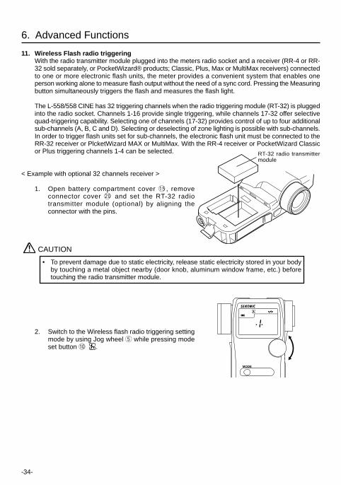
11. Wireless Flash radio triggeringWith the radio transmitter module plugged into the meters radio socket and a receiver (RR-4 or RR-32 sold separately, or PocketWizard® products; Classic, Plus, Max or MultiMax receivers) connectedto one or more electronic flash units, the meter provides a convenient system that enables oneperson working alone to measure flash output without the need of a sync cord. Pressing the Measuringbutton simultaneously triggers the flash and measures the flash light.
The L-558/558 CINE has 32 triggering channels when the radio triggering module (RT-32) is pluggedinto the radio socket. Channels 1-16 provide single triggering, while channels 17-32 offer selectivequad-triggering capability. Selecting one of channels (17-32) provides control of up to four additionalsub-channels (A, B, C and D). Selecting or deselecting of zone lighting is possible with sub-channels.In order to trigger flash units set for sub-channels, the electronic flash unit must be connected to theRR-32 receiver or PlcketWizard MAX or MultiMax. With the RR-4 receiver or PocketWizard Classicor Plus triggering channels 1-4 can be selected.
< Example with optional 32 channels receiver >
1. Open battery compartment cover !5, removeconnector cover @0 and set the RT-32 radiotransmitter module (optional) by aligning theconnector with the pins.
2. Switch to the Wireless flash radio triggering settingmode by using Jog wheel t while pressing modeset button !0 .
CAUTION
• To prevent damage due to static electricity, release static electricity stored in your bodyby touching a metal object nearby (door knob, aluminum window frame, etc.) beforetouching the radio transmitter module.
6. Advanced Functions
MODE
RT-32 radio transmittermodule
-35-
CAUTION
• When using quad channels 17-32, it is not possible to terminate this mode unless a sub-channel has been set (A, b, c or d is displayed).
6. Advanced Functions
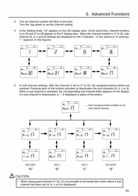
3. The set channel number will blink at this time.Turn the Jog wheel to set the channel setting.
4. In the Setting mode, “ch” appears on the ISO display area. At the same time, channel numbers(1 to 16 and 17 to 32) appear on the F display area. When the channel number is 17 to 32, sub-channel (A, b, c and d) settings are displayed on the T indicator. In the absence of settings,“-” appears in the figures.
5. In sub-channel settings, after the channel is set to 17 to 32, the assigned buttons below arepressed. Pressing each of the buttons activates or deactivates the sub-channels (A, b, c or d).When a sub-channel is activated, the corresponding sub-channel letter appears on the display.If a sub-channel is deactivated, a “-” is displayed in place of the letters.
↔ Each assigned button enables to setsub-channel directly.
AVE./∆EV M.CLEARISO 2ISO 1
“A” “d”“c”“b”
-36-
6. Advanced Functions
6. Upon setting the channel and sub-channels, press Measuring button !4 to set radio triggeringmode automatically, or the Wireless flash radio triggering mode or Wireless multiple flash radiotriggering mode is selected using the Jog wheel while the Mode set button is pressed. For othersettings of the measurement, see page 17.
7. Confirm that the meter and the radio receiver are set to the same channel number. The flashunit will fire when the measurement button of the meter is pressed and measurements can bemade at the same time.
Reference:
• Refer to the receiver instruction manual for the receiver operating method.• Maximum controllable distance of the radio flash trigger system differs depending on the
placement of the device, direction and other factors.1. Confirm the direct visible range between the transmitter and receiver.2. Place the meter and receiver away from large metal objects, concrete, objects with
large moisture content (both people and trees fall into the category) and so forth.3. Secure the radio receiver in place by using Velcro tape or mounting 1/4-20 thread.
Be sure that the entire length of the receiver antenna is higher than the flash pack atthis time. Avoid contact between the receiver antenna and metal objects at all times.
4. Depending on the location, there may be cases when the receiver is incapable ofreceiving any radio signals whatsoever.There are various possible reasons for this such as radio signals reflected from nearbyobjects. This can generally be resolved by shifting the device slightly in one directionor another.In addition, confirm that the device is not placed behind objects that readily absorb ordeflect radio signals such concrete, metal, low hills, etc.
NOTE:
• The radio flash system may be used only in countries where a permit for the controlfrequency has been issued by the government office in charge.
-37-
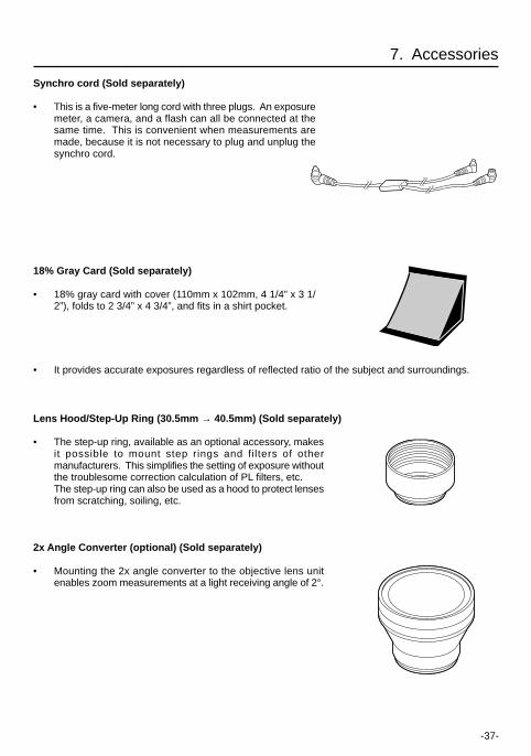
Synchro cord (Sold separately)
• This is a five-meter long cord with three plugs. An exposuremeter, a camera, and a flash can all be connected at thesame time. This is convenient when measurements aremade, because it is not necessary to plug and unplug thesynchro cord.
18% Gray Card (Sold separately)
• 18% gray card with cover (110mm x 102mm, 4 1/4” x 3 1/2”), folds to 2 3/4” x 4 3/4”, and fits in a shirt pocket.
7. Accessories
• It provides accurate exposures regardless of reflected ratio of the subject and surroundings.
Lens Hood/Step-Up Ring (30.5mm → 40.5mm) (Sold separately)
• The step-up ring, available as an optional accessory, makesit possible to mount step rings and filters of othermanufacturers. This simplifies the setting of exposure withoutthe troublesome correction calculation of PL filters, etc.The step-up ring can also be used as a hood to protect lensesfrom scratching, soiling, etc.
2x Angle Converter (optional) (Sold separately)
• Mounting the 2x angle converter to the objective lens unitenables zoom measurements at a light receiving angle of 2°.
-38-
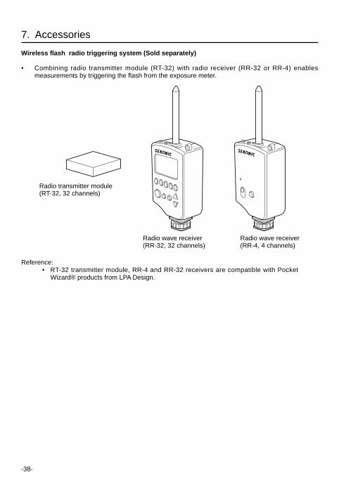
7. Accessories
Wireless flash radio triggering system (Sold separately)
• Combining radio transmitter module (RT-32) with radio receiver (RR-32 or RR-4) enablesmeasurements by triggering the flash from the exposure meter.
Reference:• RT-32 transmitter module, RR-4 and RR-32 receivers are compatible with Pocket
Wizard® products from LPA Design.
Radio transmitter module(RT-32, 32 channels)
Radio wave receiver(RR-32, 32 channels)
Radio wave receiver(RR-4, 4 channels)
-39-
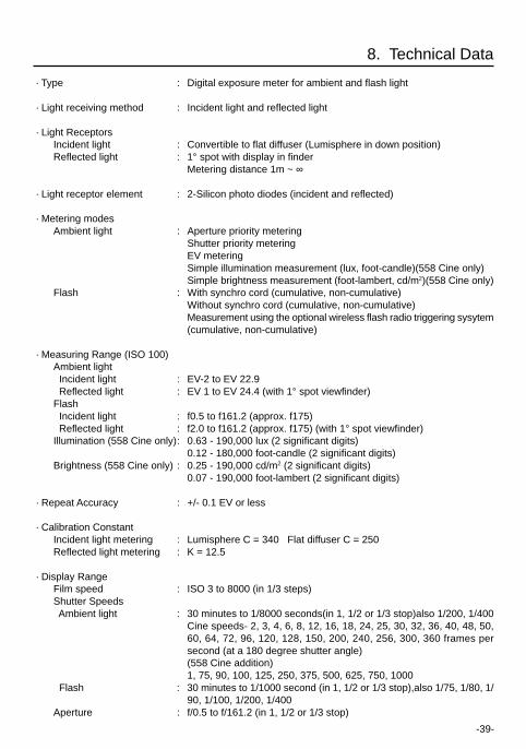
· Type : Digital exposure meter for ambient and flash light
· Light receiving method : Incident light and reflected light
· Light ReceptorsIncident light : Convertible to flat diffuser (Lumisphere in down position)Reflected light : 1° spot with display in finder
Metering distance 1m ~ ∞
· Light receptor element : 2-Silicon photo diodes (incident and reflected)
· Metering modesAmbient light : Aperture priority metering
Shutter priority meteringEV meteringSimple illumination measurement (lux, foot-candle)(558 Cine only)Simple brightness measurement (foot-lambert, cd/m2)(558 Cine only)
Flash : With synchro cord (cumulative, non-cumulative)Without synchro cord (cumulative, non-cumulative)Measurement using the optional wireless flash radio triggering sysytem(cumulative, non-cumulative)
· Measuring Range (ISO 100)Ambient light Incident light : EV-2 to EV 22.9 Reflected light : EV 1 to EV 24.4 (with 1° spot viewfinder)Flash Incident light : f0.5 to f161.2 (approx. f175) Reflected light : f2.0 to f161.2 (approx. f175) (with 1° spot viewfinder)Illumination (558 Cine only): 0.63 - 190,000 lux (2 significant digits)
0.12 - 180,000 foot-candle (2 significant digits)Brightness (558 Cine only) : 0.25 - 190,000 cd/m2 (2 significant digits)
0.07 - 190,000 foot-lambert (2 significant digits)
· Repeat Accuracy : +/- 0.1 EV or less
· Calibration ConstantIncident light metering : Lumisphere C = 340 Flat diffuser C = 250Reflected light metering : K = 12.5
· Display RangeFilm speed : ISO 3 to 8000 (in 1/3 steps)Shutter Speeds Ambient light : 30 minutes to 1/8000 seconds(in 1, 1/2 or 1/3 stop)also 1/200, 1/400
Cine speeds- 2, 3, 4, 6, 8, 12, 16, 18, 24, 25, 30, 32, 36, 40, 48, 50,60, 64, 72, 96, 120, 128, 150, 200, 240, 256, 300, 360 frames persecond (at a 180 degree shutter angle)(558 Cine addition)1, 75, 90, 100, 125, 250, 375, 500, 625, 750, 1000
Flash : 30 minutes to 1/1000 second (in 1, 1/2 or 1/3 stop),also 1/75, 1/80, 1/90, 1/100, 1/200, 1/400
Aperture : f/0.5 to f/161.2 (in 1, 1/2 or 1/3 stop)
8. Technical Data
-40-
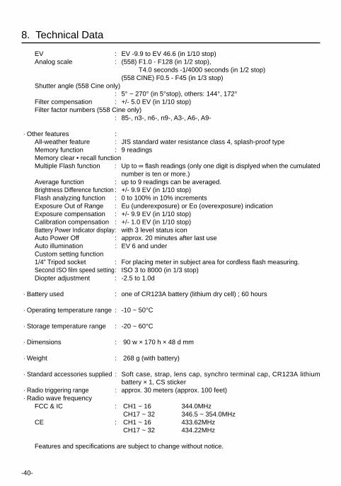
EV : EV -9.9 to EV 46.6 (in 1/10 stop)Analog scale : (558) F1.0 - F128 (in 1/2 stop),
T4.0 seconds -1/4000 seconds (in 1/2 stop)(558 CINE) F0.5 - F45 (in 1/3 stop)
Shutter angle (558 Cine only): 5° ~ 270° (in 5°stop), others: 144°, 172°
Filter compensation : +/- 5.0 EV (in 1/10 stop)Filter factor numbers (558 Cine only)
: 85-, n3-, n6-, n9-, A3-, A6-, A9-
· Other features :All-weather feature : JIS standard water resistance class 4, splash-proof typeMemory function : 9 readingsMemory clear • recall functionMultiple Flash function : Up to ∞ flash readings (only one digit is displyed when the cumulated
number is ten or more.)Average function : up to 9 readings can be averaged.Brightness Difference function : +/- 9.9 EV (in 1/10 stop)Flash analyzing function : 0 to 100% in 10% incrementsExposure Out of Range : Eu (underexposure) or Eo (overexposure) indicationExposure compensation : +/- 9.9 EV (in 1/10 stop)Calibration compensation : +/- 1.0 EV (in 1/10 stop)Battery Power Indicator display: with 3 level status iconAuto Power Off : approx. 20 minutes after last useAuto illumination : EV 6 and underCustom setting function1/4” Tripod socket : For placing meter in subject area for cordless flash measuring.Second ISO film speed setting: ISO 3 to 8000 (in 1/3 stop)Diopter adjustment : -2.5 to 1.0d
· Battery used : one of CR123A battery (lithium dry cell) ; 60 hours
· Operating temperature range : -10 ~ 50°C
· Storage temperature range : -20 ~ 60°C
· Dimensions : 90 w × 170 h × 48 d mm
· Weight : 268 g (with battery)
· Standard accessories supplied : Soft case, strap, lens cap, synchro terminal cap, CR123A lithiumbattery × 1, CS sticker
· Radio triggering range : approx. 30 meters (approx. 100 feet) · Radio wave frequency
FCC & IC : CH1 ~ 16 344.0MHz CH17 ~ 32 346.5 ~ 354.0MHz
CE : CH1 ~ 16 433.62MHz CH17 ~ 32 434.22MHz
Features and specifications are subject to change without notice.
8. Technical Data
-41-
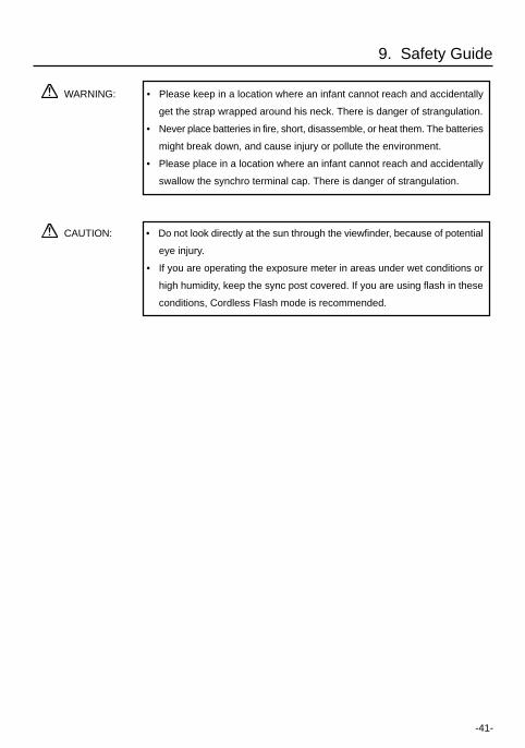
WARNING: • Please keep in a location where an infant cannot reach and accidentally
get the strap wrapped around his neck. There is danger of strangulation.
• Never place batteries in fire, short, disassemble, or heat them. The batteries
might break down, and cause injury or pollute the environment.
• Please place in a location where an infant cannot reach and accidentally
swallow the synchro terminal cap. There is danger of strangulation.
CAUTION: • Do not look directly at the sun through the viewfinder, because of potential
eye injury.
• If you are operating the exposure meter in areas under wet conditions or
high humidity, keep the sync post covered. If you are using flash in these
conditions, Cordless Flash mode is recommended.
9. Safety Guide
-42-
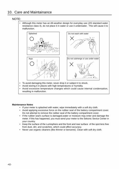
NOTE:• Although this meter has an All-weather design for everyday use (JIS standard water
resistance class 4), do not place it in water or use it underwater. This will cause it tomalfunction.
• To avoid damaging this meter, never drop it or subject it to shock.• Avoid storing it in places with high temperatures or humidity.• Avoid excessive temperature changes which could cause internal condensation,
resulting in malfunction.
10. Care and Maintainance
Splashed
Rain
Do not wash with water
Do not submerge or use under water
Maintenance Notes• If your meter is splashed with water, wipe immediately with a soft dry cloth.• Avoid applying excessive force on the rubber seal of the battery compartment cover.
Do not attempt to remove the rubber seal of the battery compartment cover.• If the rubber seal’s surface is damaged,water or moisture may enter and damage the
meter. If this has happened, you must send your meter to the Sekonic Sevice Center inyour country.
• Keep the surface of the Lumisphere and the front and rear surface of the spot lens freefrom dust, dirt, and scratches, which could affect accuracy.
• Never use organic cleaners (like thinner or benzene). Clean with soft dry cloth.
-43-
Warning: Changes or modifications to this unit not expressly approved by the party responsible forcompliance could void the user's authority to operate the equipment.
Note: This equipment has been tested and found to comply with the limits for a Class B digital device,pursuant
To Part 15 of the FCC Rules. These limits are designed to provide reasonable protection against harmfulinterference in a residential installation. This equipment generates, uses, and can radiate radio frequencyenergy and, if not installed and used in accordance with the instruction, may cause harmful interferenceto radio communication.
However, there is no guarantee that interference will not occur in a particular installation. If this equipmentdoes cause harmful interference to radio or television reception, which can be determine by turning theequipment off and on, the user is encouraged to try to correct the interference by one or more of thefollowing measures:
* Reorient or relocate the receiving antenna. * Increase the separation between the equipment and receiver. * Consult the dealer or an experienced radio/TV technician for help.
This device complies with Part 15 of the FCC rules and also with RSS-210 of Industry & Science Canada.Operation is subject to the following two condition: (1) This device may not cause harmful interference,and (2) this device must accept any interference received, including interference that may cause undesiredoperation.
FCC ID Number: PFK-558-01 IC Number: 3916-558001
FCC & IC compliance information:
-44-
7-24-14. Oizumi-Gakuen-cho, Nerima-ku, Tokyo 178-8686, JapanPhone:++81-3-3978-2335 Facsimile:++81-3-3978-5229
EU DECLARATION OF CONFORMITY
THE EU DIRECTIVE COVERED BY THIS DECLARATION:
Radio & Telecommunications Terminal Equipment Directive 1999/5/EC
PRODUCT COVERED BY THIS DECLARATION:
Name: DUALMASTER
Model: L-558 / L-558CINE
THE BASIS ON WHICH CONFORMITY IS BEING DECLARED:
The DUALMASTER L558 / L-558CINE complies with the essential requirements of the Radio &Telecommunications Terminal Equipment Directive 1999/5/EC on the basis of TechnicalConstruction File assessed by the Notified Body:
NB No. 0560Telefication B.V.Edisonstreet 12A 6902PK ZevenaarNetherlands
Printed Name: Makoto Tomono
Signed: ___________________________
Title: President
Date: August 11, 2003
Note: The device makes use of a radio frequency and which is not harmonized throughout the EU.

-45-
Memo

-46-
Memo

Blank page

7-24-14, OIZUMI-GAKUEN-CHO, NERIMA-KU, TOKYO 178-8686 JAPAN
TEL:+81(0)3-3978-2335 FAX:+81(0)3-3978-5229
http://www.sekonic.co.jp/English
JD1297560-01


