38
DUCTILE IRON PIPES & FITTINGS Ductile Iron Pipes, Fittings & Valves for potable water, reclaimed water, sewerage and gas applications

DUCTILE IRON
PIPES & FITTINGS
Ductile Iron Pipes, Fittings & Valves
for potable water, reclaimed water, sewerage and gas applications


Standards & Specification
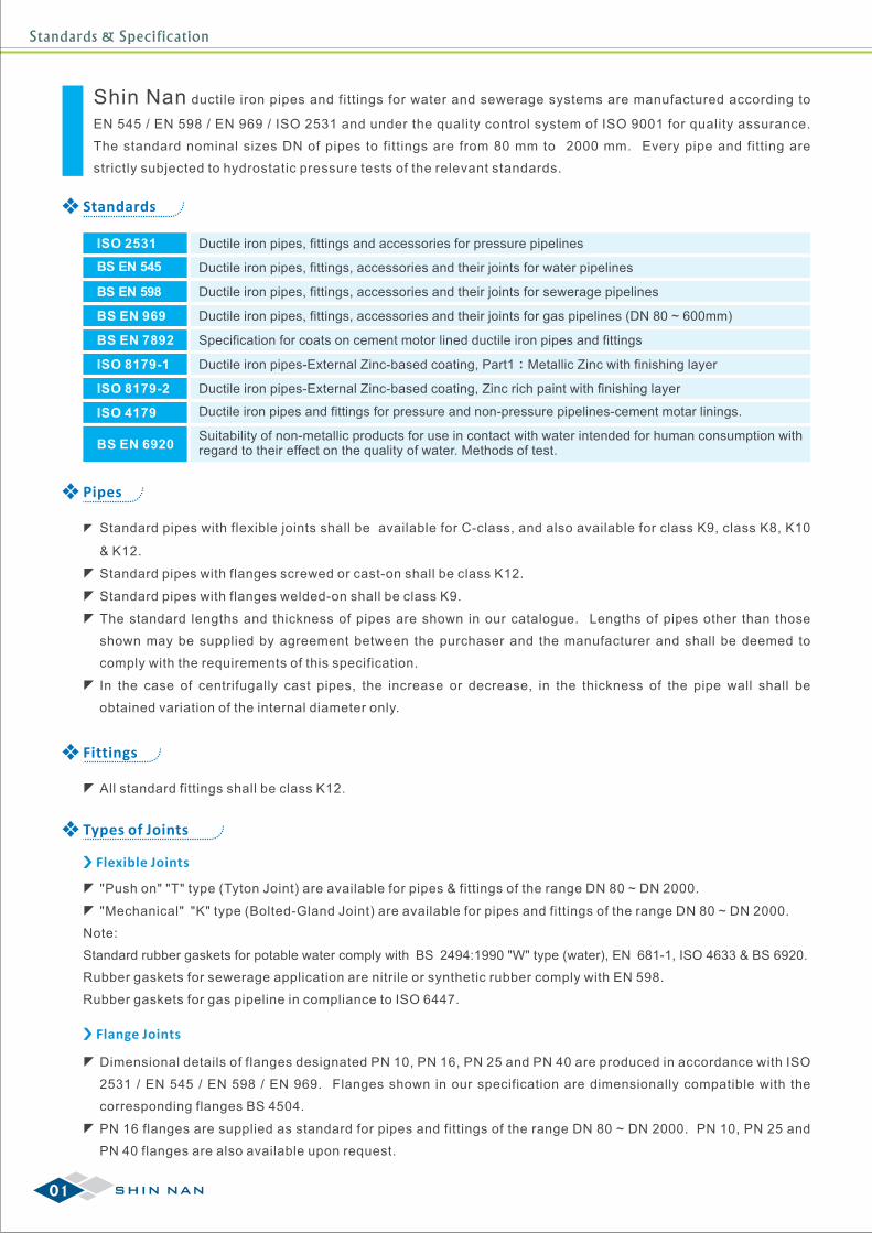
Shin Nan ductile iron pipes and fittings for water and sewerage systems are manufactured according to
EN 545 / EN 598 / EN 969 / ISO 2531 and under the quality control system of ISO 9001 for quality assurance.
The standard nominal sizes DN of pipes to fittings are from 80 mm to 2000 mm. Every pipe and fitting are
strictly subjected to hydrostatic pressure tests of the relevant standards.
Pipes
zStandard pipes with flexible joints s available for C-class,
& K12.
zStandard pipes with flanges screwed or cast-on shall be class K12.
zStandard pipes with flanges welded-on shall be class K9.
zThe standard lengths and thickness of pipes are shown in our catalogue. Lengths of pipes other than those
shown may be supplied by agreement between the purchaser and the manufacturer and shall be deemed to
comply with the requirements of this specification.
zIn the case of centrifugally cast pipes, the increase or decrease, in the thickness of the pipe wall shall be
obtained variation of the internal diameter only.
hall be and also available for class K9, class K8, K10
Fittings
All standard fittings shall be class K12.
Types of Joints
Flexible Joints
"Push on" "T" type (Tyton Joint) are available for pipes & fittings of the range DN 80 ~ DN 2000.
"Mechanical" "K" type (Bolted-Gland Joint) are available for pipes and fittings of the range DN 80 ~ DN 2000.
Note:
Standard rubber gaskets for potable water comply with BS 2494:1990 "W" type (water), EN 681-1, ISO 4633 & BS 6920.
Rubber gaskets for sewerage application are nitrile or synthetic rubber comply with EN 598.
Rubber gaskets for gas pipeline in compliance to ISO 6447.
Flange Joints
zDimensional details of flanges designated PN 10, PN 16, PN 25 and PN 40 are produced in accordance with ISO
2531 / EN 545 / EN 598 / EN 969. Flanges shown in our specification are dimensionally compatible with the
corresponding flanges BS 4504.
zPN 16 flanges are supplied as standard for pipes and fittings of the range DN 80 ~ DN 2000. PN 10, PN 25 and
PN 40 flanges are also available upon request.
01 SHIN NAN
Standards
Ductile iron pipes, fittings and accessories for pressure pipelines
Ductile iron pipes, fittings, accessories and their joints for water pipelines
Specification for coats on cement motor lined ductile iron pipes and fittings
Ductile iron pipes, fittings, accessories and their joints for sewerage pipelines
Ductile iron pipes-External Zinc-based coating, Part1:Metallic Zinc with finishing layer
Ductile iron pipes, fittings, accessories and their joints for gas pipelines (DN 80 ~ 600mm)
Ductile iron pipes-External Zinc-based coating, Zinc rich paint with finishing layer
Suitability of non-metallic products for use in contact with water intended for human consumption withregard to their effect on the quality of water. Methods of test.
ISO 2531
BS EN 545
BS EN 7892
ISO 8179-1
BS EN 969
ISO 8179-2
BS EN 6920
BS EN 598
Ductile iron pipes and fittings for pressure and non-pressure pipelines-cement motar linings.ISO 4179

Standards & Specification
02SHIN NAN
Angular Deflection & Straight Draw of "Push-in" Type Flexible Joint (Tyton Joint)
DN(Nominal size) mm Allowable Angular Deflection
80 ~ 300
350 ~ 600
700 ~ 800
900 ~ 1200
1400 ~ 1600
1800 ~ 2000
o5o4o4
4o
o4o1.5
38 mm
38 mm
56 mm
70 mm
95 mm
105 mm
Allowable Straight DrawWithout Deflection
Pressure & Temperature Ratings
DN
(Nominal size) mm bar K<9 bar
80 ~ 300
350 ~ 600
700 ~ 1200
1400 ~ 2000
50
40
32
25
25
16
10
10
Works proof and leak tightness pressures for K class
o ozThe nominal pressure rating are applicable to the temperature range -10 C to 80 C; the purchasers should
be consulted with the manufacturers where pressure-temperature conditions are out of this range.
Pipes Fittings
bar K 9³20.5(K+1)
20.5 K20.5(K-1)20.5(K-2)
Tolerances on Dimensions
Tolerances on External Diameters (DE)
DN ToleranceDE DEDN
Straightness of Pipes
Pipes shall be straight with a maximum deviation of 0.125% of their length.
Tolerance
80
100
150
200
250
300
350
400
450
500
600
700
800
900
1000
1100
1200
1400
1500
1600
1800
2000
+1 / -2.7
+1 / -2.8
+1 / -2.9
+1 / -3.0
+1 / -3.1
+1 / -3.3
+1 / -3.4
+1 / -3.5
+1/ -3.6
+1 / -3.8
+1 / -4.0
+1 / -4.3
+1 / -4.5
98
118
170
222
274
326
378
429
480
532
635
738
842
945
1048
1152
1255
1462
1565
1668
1875
2082
+1 / -4.8
+1 / -5.0
+1 / -6.0
+1 / -5.8
+1 / -6.6
+1 / -7.0
+1 / -7.4
+1 / -8.2
+1/ -9.0
Tolerances on Wall Thickness (e) for K class
ToleranceType of Casting
Pipes centrifugally cast
Pipes do not centrifugally cast and fittings
Tolerance
- (1.3 + 0.001 DN)
Tolerances on Lengths
ToleranceType of Casting
Socket and spigot pipes (full length or shortened)
Fitting for socketed joint
Pipes and Fitting for flanged joint
Tolerance
+ 70 , -30
± 20
± 10
- (2.3 + 0.001 DN)
Dimensions in mm
Internal Diameter
ToleranceDN
400-1000
Limit Deviation
- 10
- 0.01 DN1100-2000
Standards & Specification
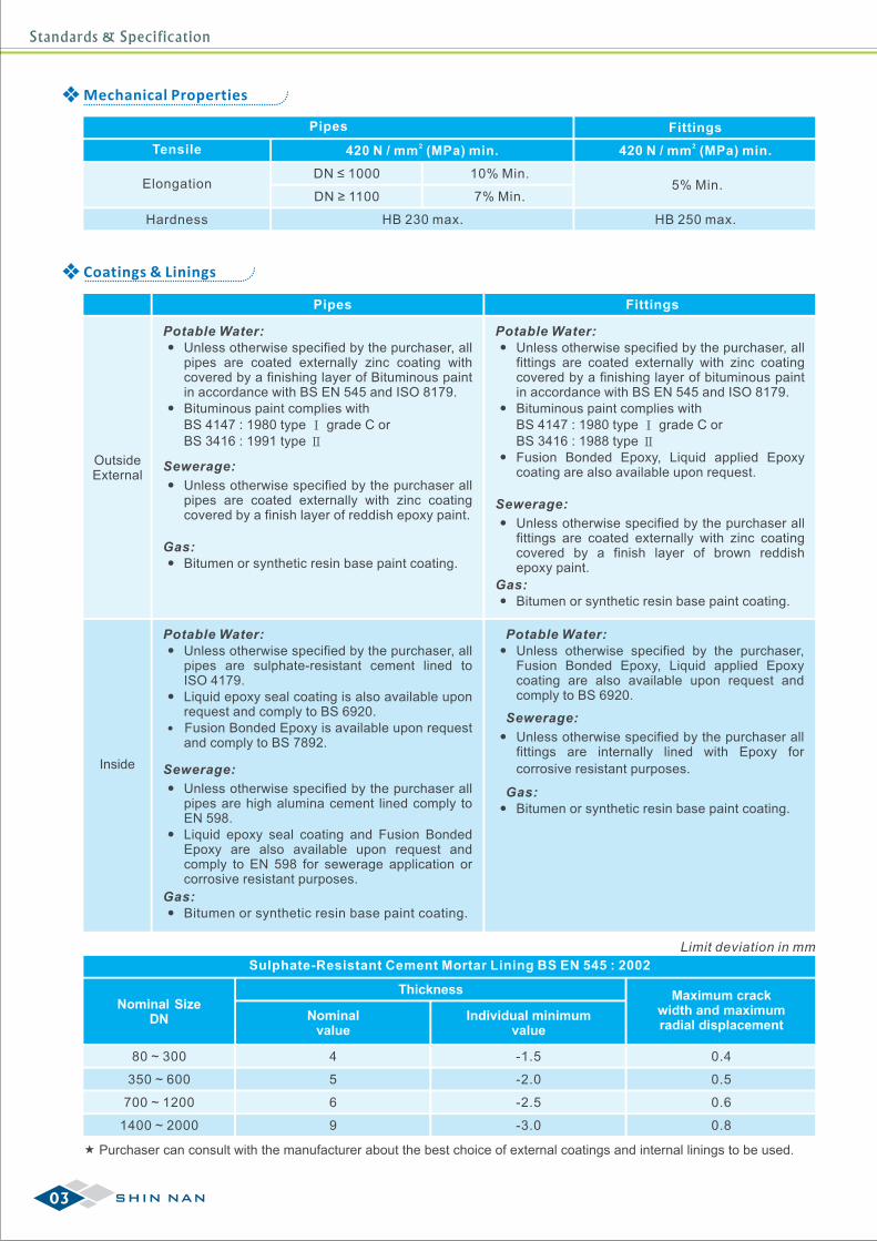
Mechanical Properties
Tensile
Pipes Fittings2420 N / mm (MPa) min.
Elongation
2420 N / mm (MPa) min.
Hardness
DN ≤ 1000
DN ≥ 1100
10% Min.
7% Min.
HB 230 max.
5% Min.
HB 250 max.
Sulphate-Resistant Cement Mortar Lining BS EN 545 : 2002
Nominalvalue
Individual minimumvalue
ThicknessNominal Size
DN
Maximum crackwidth and maximumradial displacement
Limit deviation in mm
80 ~ 300
350 ~ 600
700 ~ 1200
1400 ~ 2000
4
5
6
9
-1.5
-2.0
-2.5
-3.0
0.4
0.5
0.6
0.8
Purchaser can consult with the manufacturer about the best choice of external coatings and internal linings to be used.
03 SHIN NAN
Coatings & Linings
Pipes Fittings
OutsideExternal
pipes are coated externally zinc coating with covered by a finishing layer of Bituminous paint in accordance with BS EN 545 and ISO 8179.
Bituminous paint complies withBS 4147 : 1980 type Ⅰ grade C orBS 3416 : 1991 type Ⅱ
Unless otherwise specified by the purchaser, all Potable Water:
pipes are coated externally with zinc coating covered by a finish layer of reddish epoxy paint.
Unless otherwise specified by the purchaser all
Sewerage:
Bitumen or synthetic resin base paint coating.Gas:
fittings are coated externally with zinc coating covered by a finishing layer of bituminous paint in accordance with BS EN 545 and ISO 8179.
Bituminous paint complies withBS 4147 : 1980 type Ⅰ grade C orBS 3416 : 1988 type Ⅱ
Fusion Bonded Epoxy, Liquid applied Epoxy coating are also available upon request.
Unless otherwise specified by the purchaser, all Potable Water:
Sewerage:
fittings are coated externally with zinc coating covered by a finish layer of brown reddish epoxy paint.
Unless otherwise specified by the purchaser all
Bitumen or synthetic resin base paint coating.Gas:
Inside
pipes are sulphate-resistant cement lined to ISO 4179.
Liquid epoxy seal coating is also available upon request and comply to BS 6920.
Fusion Bonded Epoxy is available upon request and comply to BS 7892.
Unless otherwise specified by the purchaser, all Potable Water:
Sewerage:
Bitumen or synthetic resin base paint coating.Gas:
pipes are high alumina cement lined comply to EN 598.
Liquid epoxy seal coating and Fusion Bonded Epoxy are also available upon request and comply to EN 598 for sewerage application or corrosive resistant purposes.
Unless otherwise specified by the purchaser all
Fusion Bonded Epoxy, Liquid applied Epoxy coating are also available upon request and comply to BS 6920.
Unless otherwise specified by the purchaser,Potable Water:
Sewerage:
Bitumen or synthetic resin base paint coating.Gas:
fittings are internally lined with Epoxy for
corrosive resistant purposes.
Unless otherwise specified by the purchaser all
e' e
ED
L
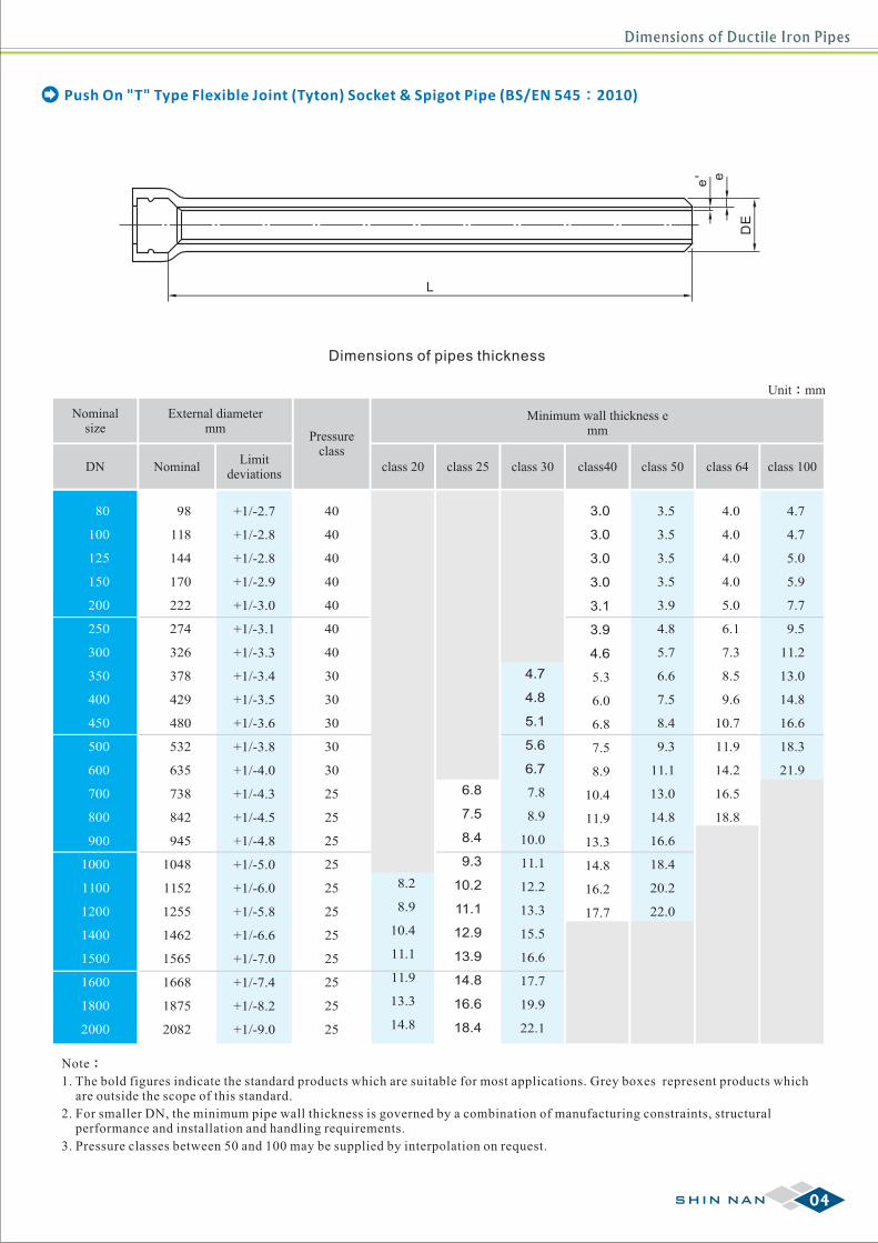
Dimensions of pipes thickness
Push On "T" Type Flexible Joint (Tyton) Socket & Spigot Pipe (BS/EN 545:2010)
Unit:mm
DN
80
100
125
150
200
250
300
350
400
450
500
600
700
800
900
1000
1100
1200
1400
1500
1600
1800
2000
Nominalsize
NominalLimit
deviations
External diametermm
98
118
144
170
222
274
326
378
429
480
532
635
738
842
945
1048
1152
1255
1462
1565
1668
1875
2082
+1/-2.7
+1/-2.8
+1/-2.8
+1/-2.9
+1/-3.0
+1/-3.1
+1/-3.3
+1/-3.4
+1/-3.5
+1/-3.6
+1/-3.8
+1/-4.0
+1/-4.3
+1/-4.5
+1/-4.8
+1/-5.0
+1/-6.0
+1/-5.8
+1/-6.6
+1/-7.0
+1/-7.4
+1/-8.2
+1/-9.0
8.2
8.9
10.4
11.1
11.9
13.3
14.8
6.8
7.5
8.4
9.3
10.2
11.1
12.9
13.9
14.8
16.6
18.4
4.7
4.8
5.1
5.6
6.7
7.8
8.9
10.0
11.1
12.2
13.3
15.5
16.6
17.7
19.9
22.1
3.0
3.0
3.0
3.0
3.1
3.9
4.6
5.3
6.0
6.8
7.5
8.9
10.4
11.9
13.3
14.8
16.2
17.7
3.5
3.5
3.5
3.5
3.9
4.8
5.7
6.6
7.5
8.4
9.3
11.1
13.0
14.8
16.6
18.4
20.2
22.0
4.0
4.0
4.0
4.0
5.0
6.1
7.3
8.5
9.6
10.7
11.9
14.2
16.5
18.8
4.7
4.7
5.0
5.9
7.7
9.5
11.2
13.0
14.8
16.6
18.3
21.9
Minimum wall thickness emm
class 20 class 25 class 30 class40 class 50 class 64 class 100
Note:
1. The bold figures indicate the standard products which are suitable for most applications. Grey boxes represent products which are outside the scope of this standard.
2. For smaller DN, the minimum pipe wall thickness is governed by a combination of manufacturing constraints, structural performance and installation and handling requirements.
3. Pressure classes between 50 and 100 may be supplied by interpolation on request.
40
40
40
40
40
40
40
30
30
30
30
30
25
25
25
25
25
25
25
25
25
25
25
Pressureclass
04SHIN NAN
Dimensions of Ductile Iron Pipes
e' e
ED
L
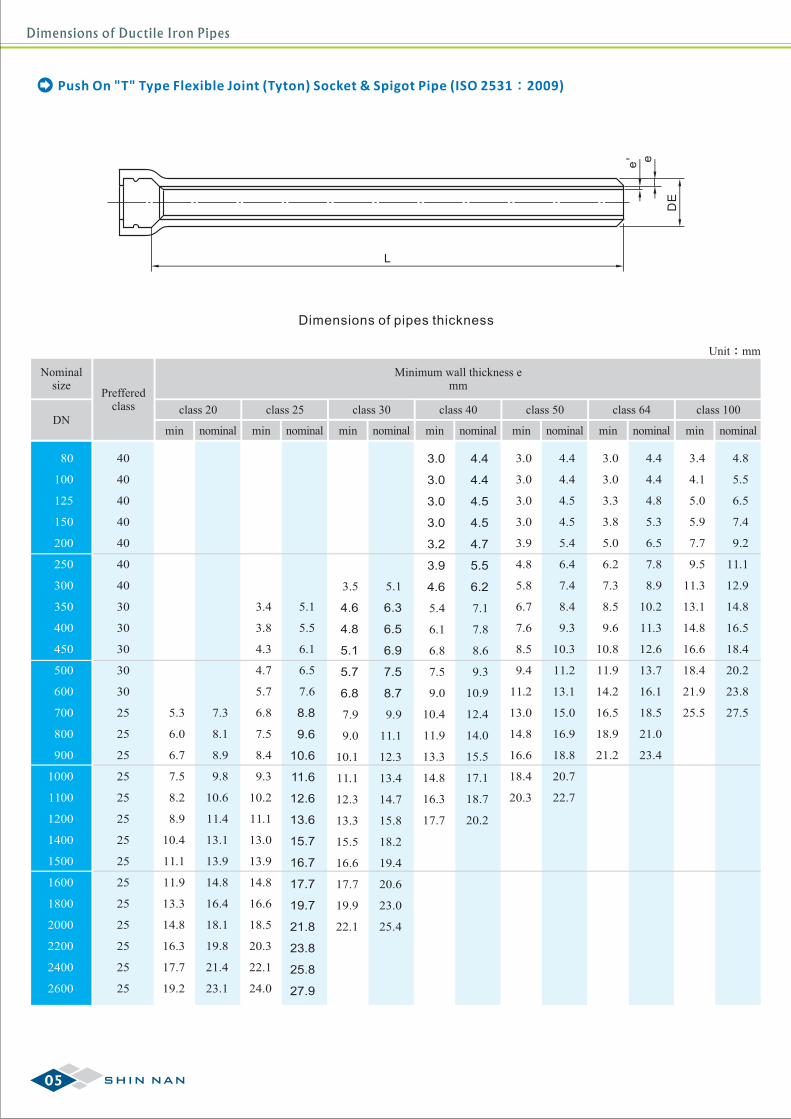
Dimensions of pipes thickness
Push On "T" Type Flexible Joint (Tyton) Socket & Spigot Pipe (ISO 2531:2009)
Unit:mm
DN
80
100
125
150
200
250
300
350
400
450
500
600
700
800
900
1000
1100
1200
1400
1500
1600
1800
2000
2200
2400
2600
Nominalsize
5.3
6.0
6.7
7.5
8.2
8.9
10.4
11.1
11.9
13.3
14.8
16.3
17.7
19.2
3.4
3.8
4.3
4.7
5.7
6.8
7.5
8.4
9.3
10.2
11.1
13.0
13.9
14.8
16.6
18.5
20.3
22.1
24.0
3.5
4.6
4.8
5.1
5.7
6.8
7.9
9.0
10.1
11.1
12.3
13.3
15.5
16.6
17.7
19.9
22.1
3.0
3.0
3.0
3.0
3.2
3.9
4.6
5.4
6.1
6.8
7.5
9.0
10.4
11.9
13.3
14.8
16.3
17.7
3.0
3.0
3.0
3.0
3.9
4.8
5.8
6.7
7.6
8.5
9.4
11.2
13.0
14.8
16.6
18.4
20.3
3.0
3.0
3.3
3.8
5.0
6.2
7.3
8.5
9.6
10.8
11.9
14.2
16.5
18.9
21.2
3.4
4.1
5.0
5.9
7.7
9.5
11.3
13.1
14.8
16.6
18.4
21.9
25.57.3
8.1
8.9
9.8
10.6
11.4
13.1
13.9
14.8
16.4
18.1
19.8
21.4
23.1
5.1
5.5
6.1
6.5
7.6
8.8
9.6
10.6
11.6
12.6
13.6
15.7
16.7
17.7
19.7
21.8
23.8
25.8
27.9
5.1
6.3
6.5
6.9
7.5
8.7
9.9
11.1
12.3
13.4
14.7
15.8
18.2
19.4
20.6
23.0
25.4
4.4
4.4
4.5
4.5
4.7
5.5
6.2
7.1
7.8
8.6
9.3
10.9
12.4
14.0
15.5
17.1
18.7
20.2
4.4
4.4
4.5
4.5
5.4
6.4
7.4
8.4
9.3
10.3
11.2
13.1
15.0
16.9
18.8
20.7
22.7
4.4
4.4
4.8
5.3
6.5
7.8
8.9
10.2
11.3
12.6
13.7
16.1
18.5
21.0
23.4
4.8
5.5
6.5
7.4
9.2
11.1
12.9
14.8
16.5
18.4
20.2
23.8
27.5
Minimum wall thickness emm
min min min min min minnominal nominal nominal nominal nominal nominal nominal
40
40
40
40
40
40
40
30
30
30
30
30
25
25
25
25
25
25
25
25
25
25
25
25
25
25
Prefferedclass
min
class 20 class 25 class 30 class 40 class 50 class 64 class 100
05 SHIN NAN
Dimensions of Ductile Iron Pipes
Dimensions of Ductile Iron Pipes
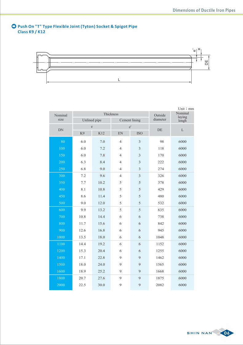
Class K9 / K12Push On "T" Type Flexible Joint (Tyton) Socket & Spigot Pipe
e' e
ED
L
Unit:mm
DN
80
100
150
200
250
300
350
400
450
500
600
700
800
900
1000
1100
1200
1400
1500
1600
1800
2000
K9
Nominalsize
K12
Unlined pipe Cement lining
Thickness
DEISO
e'
Outsidediameter
Nominallayinglengh
LEN
6.0
6.0
6.0
6.3
6.8
7.2
7.7
8.1
8.6
9.0
9.9
10.8
11.7
12.6
13.5
14.4
15.3
17.1
18.0
18.9
20.7
22.5
7.0
7.2
7.8
8.4
9.0
9.6
10.2
10.8
11.4
12.0
13.2
14.4
15.6
16.8
18.0
19.2
20.4
22.8
24.0
25.2
27.6
30.0
4
4
4
4
4
4
5
5
5
5
5
6
6
6
6
6
6
9
9
9
9
9
3
3
3
3
3
3
5
5
5
5
5
6
6
6
6
6
6
9
9
9
9
9
6000
6000
6000
6000
6000
6000
6000
6000
6000
6000
6000
6000
6000
6000
6000
6000
6000
6000
6000
6000
6000
6000
e
98
118
170
222
274
326
378
429
480
532
635
738
842
945
1048
1152
1255
1462
1565
1668
1875
2082
06SHIN NAN
Dimensions of Ductile Iron Fittings
L1
L
Puddle flange
L1
L
Puddle flange
L1
L
Puddle flange
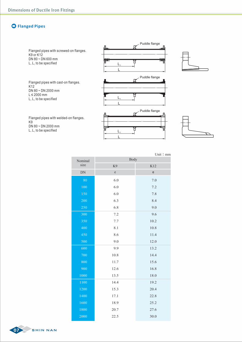
Flanged pipes with screwed-on flanges.K9 or K12DN 80 ~ DN 600 mmL, L to be specified1
Flanged pipes with welded-on flanges.K9DN 80 ~ DN 2000 mmL, L to be specified1
Flanged pipes with cast-on flanges.K12DN 80 ~ DN 2000 mmL ≤ 2000 mmL, L to be specified1
Unit:mm
Nominalsize K9 K12
Body
80
100
150
200
250
300
350
400
450
500
600
700
800
900
1000
1100
1200
1400
1600
1800
2000
e e
6.0
6.0
6.0
6.3
6.8
7.2
7.7
8.1
8.6
9.0
9.9
10.8
11.7
12.6
13.5
14.4
15.3
17.1
18.9
20.7
22.5
7.0
7.2
7.8
8.4
9.0
9.6
10.2
10.8
11.4
12.0
13.2
14.4
15.6
16.8
18.0
19.2
20.4
22.8
25.2
27.6
30.0
DN
Flanged Pipes
07 SHIN NAN
Dimensions of Ductile Iron Fittings
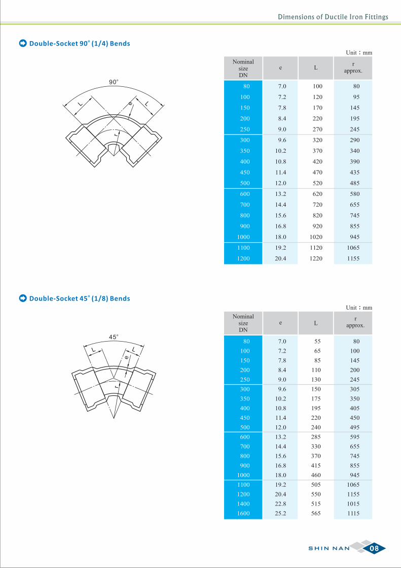
oDouble-Socket 45 (1/8) Bends
Unit:mm
NominalsizeDN
80
100
150
200
250
300
350
400
450
500
600
700
800
900
1000
1100
1200
e Lr
approx.
7.0
7.2
7.8
8.4
9.0
9.6
10.2
10.8
11.4
12.0
13.2
14.4
15.6
16.8
18.0
19.2
20.4
100
120
170
220
270
320
370
420
470
520
620
720
820
920
1020
1120
1220
80
95
145
195
245
290
340
390
435
485
580
655
745
855
945
1065
1155
Unit:mm
NominalsizeDN
80
100
150
200
250
300
350
400
450
500
600
700
800
900
1000
1100
1200
1400
1600
rapprox.
o90
L Le
r
o45
L L
e
r
oDouble-Socket 90 (1/4) Bends
80
100
145
200
245
305
350
405
450
495
595
655
745
855
945
1065
1155
1015
1115
L
55
65
85
110
130
150
175
195
220
240
285
330
370
415
460
505
550
515
565
e
7.0
7.2
7.8
8.4
9.0
9.6
10.2
10.8
11.4
12.0
13.2
14.4
15.6
16.8
18.0
19.2
20.4
22.8
25.2
08SHIN NAN
Dimensions of Ductile Iron Fittings
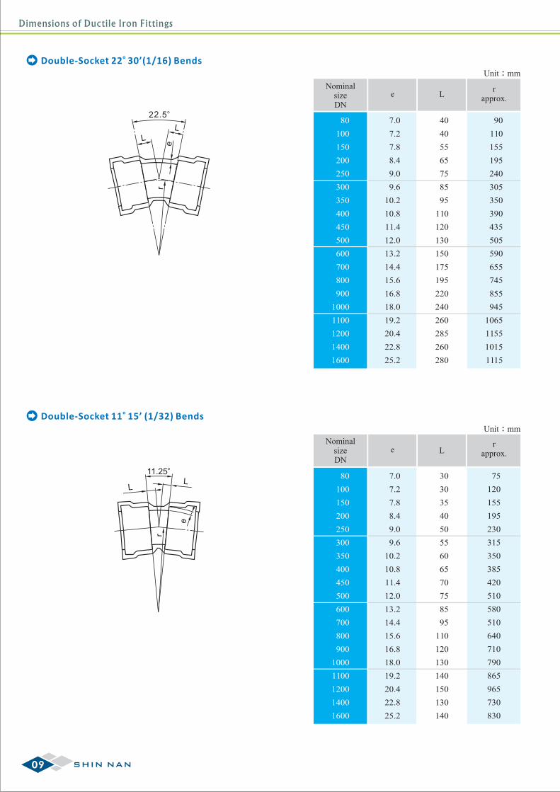
oDouble-Socket 11 15’ (1/32) Bends
o22.5
L
L
er
Unit:mm
NominalsizeDN
e Lr
approx.
80
100
150
200
250
300
350
400
450
500
600
700
800
900
1000
1100
1200
1400
1600
30
30
35
40
50
55
60
65
70
75
85
95
110
120
130
140
150
130
140
75
120
155
195
230
315
350
385
420
510
580
510
640
710
790
865
965
730
830
oDouble-Socket 22 30’(1/16) Bends
e
LL
r
o11.25
Unit:mm
NominalsizeDN
rapprox.
80
100
150
200
250
300
350
400
450
500
600
700
800
900
1000
1100
1200
1400
1600
90
110
155
195
240
305
350
390
435
505
590
655
745
855
945
1065
1155
1015
1115
L
40
40
55
65
75
85
95
110
120
130
150
175
195
220
240
260
285
260
280
e
7.0
7.2
7.8
8.4
9.0
9.6
10.2
10.8
11.4
12.0
13.2
14.4
15.6
16.8
18.0
19.2
20.4
22.8
25.2
7.0
7.2
7.8
8.4
9.0
9.6
10.2
10.8
11.4
12.0
13.2
14.4
15.6
16.8
18.0
19.2
20.4
22.8
25.2
09 SHIN NAN
Dimensions of Ductile Iron Fittings
Unit:mm
Nominal size
80
100
150
200
250
300
350
400
450
500
80
80
100
80
100
150
80
100
150
200
80
100
150
200
250
80
100
150
200
250
300
80
100
150
200
250
300
350
80
100
150
200
250
300
350
400
80
100
150
200
250
300
350
400
450
80
100
150
200
250
300
350
400
450
500
7.0
7.2
7.2
7.8
7.8
7.8
8.4
8.4
8.4
8.4
9.0
9.0
9.0
9.0
9.0
9.6
9.6
9.6
9.6
9.6
9.6
10.2
10.2
10.2
10.2
10.2
10.2
10.2
10.8
10.8
10.8
10.8
10.8
10.8
10.8
10.8
11.4
11.4
11.4
11.4
11.4
11.4
11.4
11.4
11.4
12.0
12.0
12.0
12.0
12.0
12.0
12.0
12.0
12.0
12.0
170
170
190
170
195
255
175
200
255
315
180
200
260
315
375
180
205
260
320
375
435
185
205
265
325
380
440
495
185
210
270
325
385
440
500
560
190
215
270
330
385
445
505
560
620
195
215
275
330
390
450
505
565
620
680
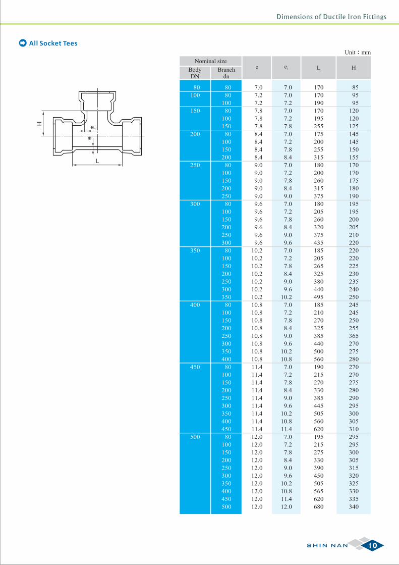
BodyDN
Branchdn
e e1 L
H
L
e1
e
All Socket Tees
85
95
95
120
120
125
145
145
150
155
170
170
175
180
190
195
195
200
205
210
220
220
220
225
230
235
240
250
245
245
250
255
365
270
275
280
270
270
275
280
290
295
300
305
310
295
295
300
305
315
320
325
330
335
340
H
7.0
7.0
7.2
7.0
7.2
7.8
7.0
7.2
7.8
8.4
7.0
7.2
7.8
8.4
9.0
7.0
7.2
7.8
8.4
9.0
9.6
7.0
7.2
7.8
8.4
9.0
9.6
10.2
7.0
7.2
7.8
8.4
9.0
9.6
10.2
10.8
7.0
7.2
7.8
8.4
9.0
9.6
10.2
10.8
11.4
7.0
7.2
7.8
8.4
9.0
9.6
10.2
10.8
11.4
12.0
10SHIN NAN
Dimensions of Ductile Iron Fittings
Unit:mm
Nominal size
600
700
800
900
80
100
150
200
250
300
350
400
450
500
600
150
200
250
300
350
400
450
500
600
700
150
200
250
300
350
400
450
500
600
700
800
150
200
250
300
350
400
450
500
600
700
800
900
13.2
13.2
13.2
13.2
13.2
13.2
13.2
13.2
13.2
13.2
13.2
14.4
14.4
14.4
14.4
14.4
14.4
14.4
14.4
14.4
14.4
15.6
15.6
15.6
15.6
15.6
15.6
15.6
15.6
15.6
15.6
15.6
16.8
16.8
16.8
16.8
16.8
16.8
16.8
16.8
16.8
16.8
16.8
16.8
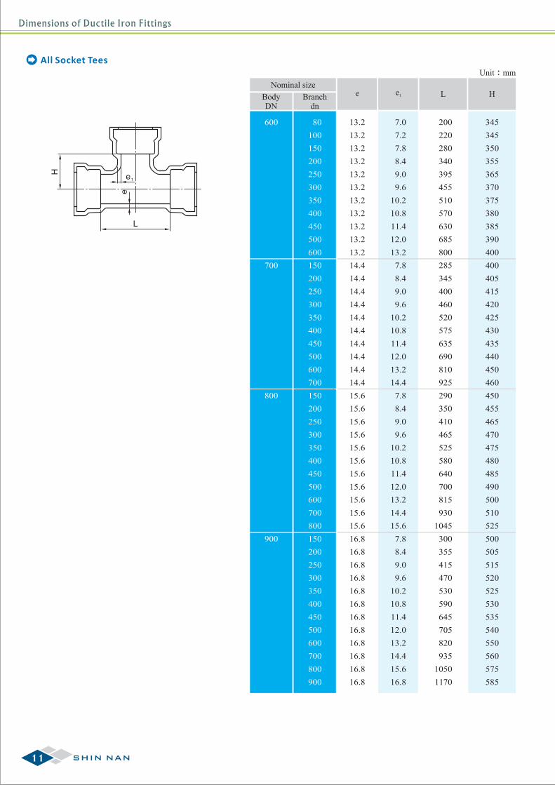
BodyDN
Branchdn
e e1
All Socket TeesH
L
e1
e345
345
350
355
365
370
375
380
385
390
400
400
405
415
420
425
430
435
440
450
460
450
455
465
470
475
480
485
490
500
510
525
500
505
515
520
525
530
535
540
550
560
575
585
H
200
220
280
340
395
455
510
570
630
685
800
285
345
400
460
520
575
635
690
810
925
290
350
410
465
525
580
640
700
815
930
1045
300
355
415
470
530
590
645
705
820
935
1050
1170
L
7.0
7.2
7.8
8.4
9.0
9.6
10.2
10.8
11.4
12.0
13.2
7.8
8.4
9.0
9.6
10.2
10.8
11.4
12.0
13.2
14.4
7.8
8.4
9.0
9.6
10.2
10.8
11.4
12.0
13.2
14.4
15.6
7.8
8.4
9.0
9.6
10.2
10.8
11.4
12.0
13.2
14.4
15.6
16.8
11 SHIN NAN
Dimensions of Ductile Iron Fittings
Unit:mm
Nominal size
1000
1100
1200
200
250
300
350
400
450
500
600
700
800
900
1000
150
200
250
300
350
400
450
500
600
700
800
900
1000
1100
150
200
250
300
350
400
450
500
600
700
800
900
1000
1100
1200
150 18.0
18.0
18.0
18.0
18.0
18.0
18.0
18.0
18.0
18.0
18.0
18.0
18.0
19.2
19.2
19.2
19.2
19.2
19.2
19.2
19.2
19.2
19.2
19.2
19.2
19.2
19.2
20.4
20.4
20.4
20.4
20.4
20.4
20.4
20.4
20.4
20.4
20.4
20.4
20.4
20.4
20.4
305
360
420
480
535
595
650
710
825
940
1060
1175
1290
310
370
425
485
540
600
660
715
830
950
1065
1180
1295
1410
315
375
430
490
550
605
665
720
840
955
1070
1185
1300
1420
1535
550
555
565
570
575
580
585
590
600
610
625
635
645
600
605
615
620
625
630
635
640
650
660
675
685
695
705
650
655
665
670
675
680
685
690
700
710
725
735
745
750
765
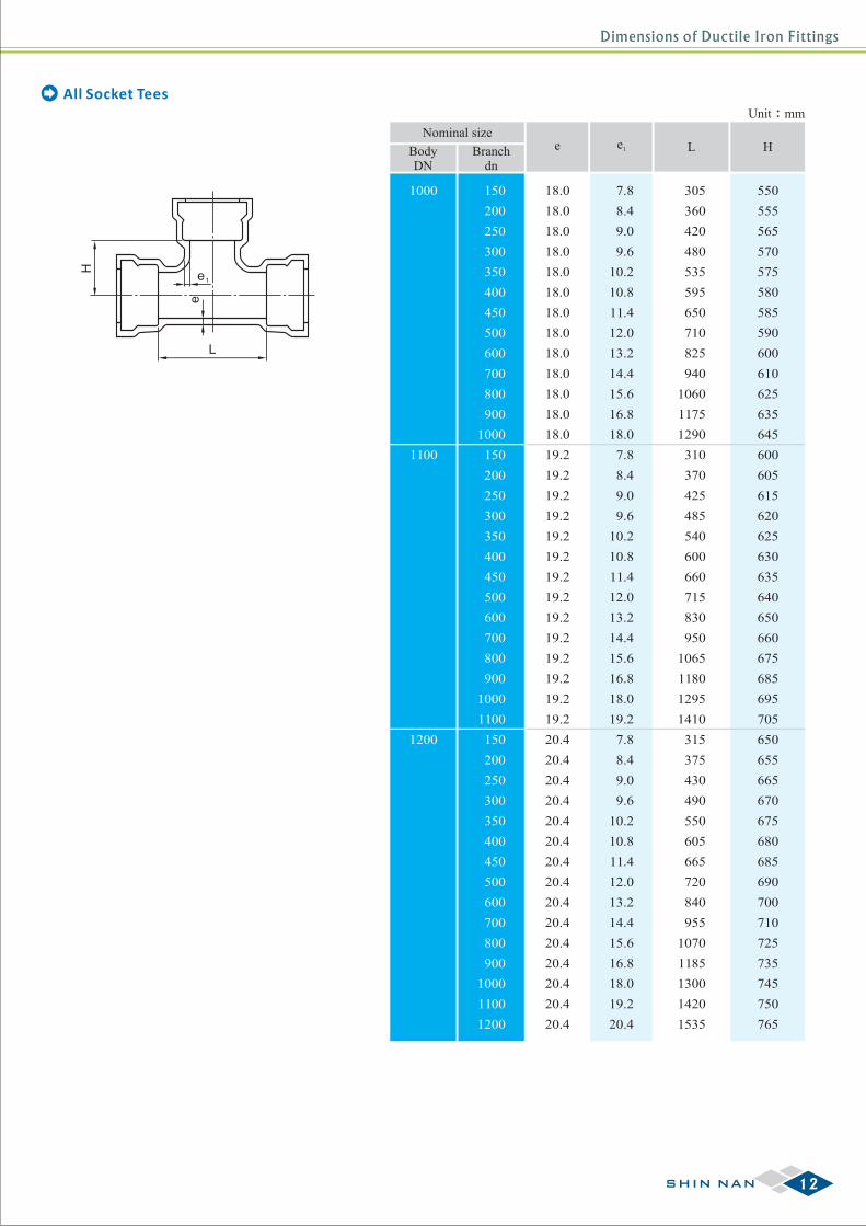
BodyDN
Branchdn
e e1 L H
All Socket TeesH
L
e1
e7.8
8.4
9.0
9.6
10.2
10.8
11.4
12.0
13.2
14.4
15.6
16.8
18.0
7.8
8.4
9.0
9.6
10.2
10.8
11.4
12.0
13.2
14.4
15.6
16.8
18.0
19.2
7.8
8.4
9.0
9.6
10.2
10.8
11.4
12.0
13.2
14.4
15.6
16.8
18.0
19.2
20.4
12SHIN NAN
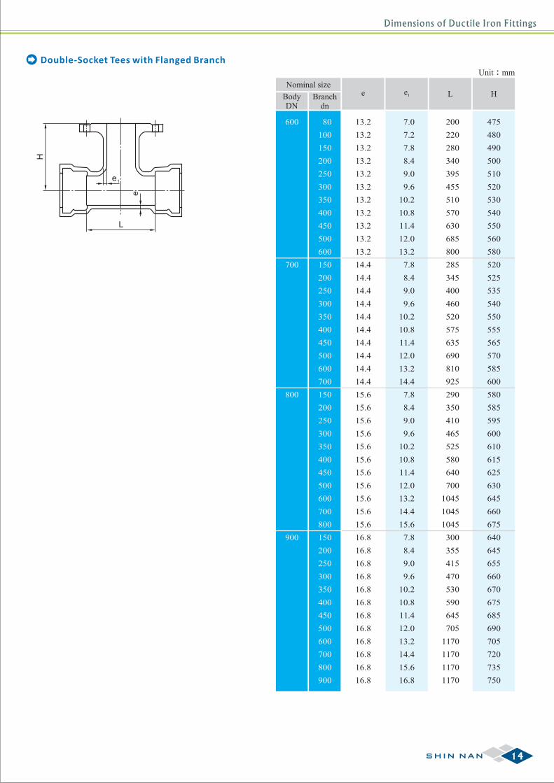
Dimensions of Ductile Iron Fittings
80
100
150
200
250
300
350
400
450
500
80
80
100
80
100
150
80
100
150
200
80
100
150
200
250
80
100
150
200
250
300
80
100
150
200
250
300
350
80
100
150
200
250
300
350
400
80
100
150
200
250
300
350
400
450
80
100
150
200
250
300
350
400
450
500
Unit:mm
Nominal size
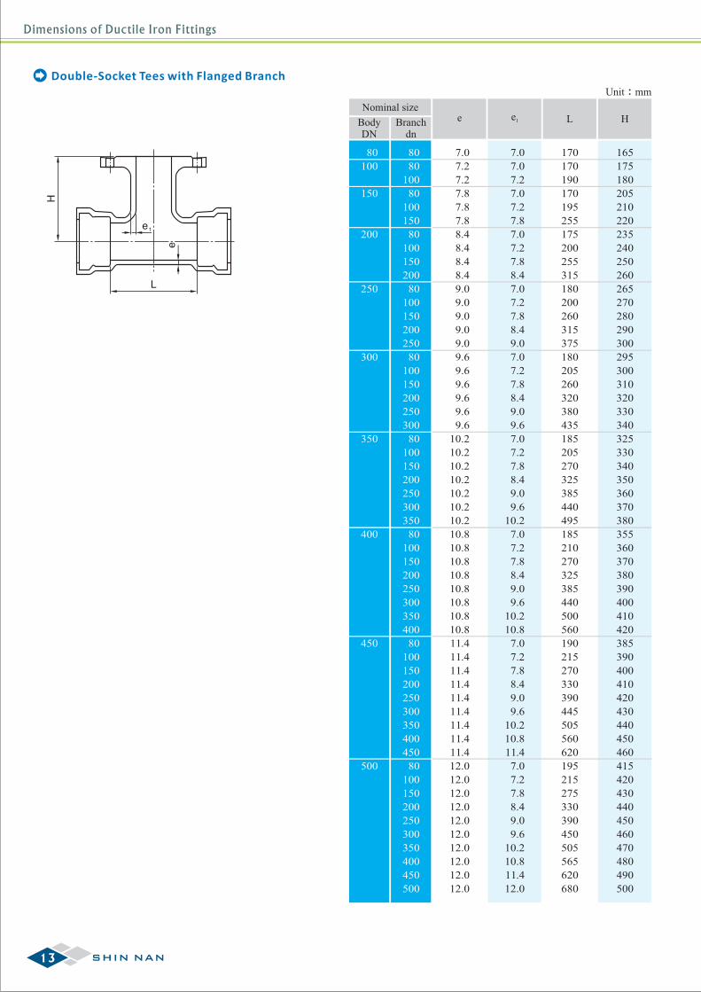
BodyDN
Branchdn
e e1 L H
H
L
e1
e
Double-Socket Tees with Flanged Branch
7.0
7.2
7.2
7.8
7.8
7.8
8.4
8.4
8.4
8.4
9.0
9.0
9.0
9.0
9.0
9.6
9.6
9.6
9.6
9.6
9.6
10.2
10.2
10.2
10.2
10.2
10.2
10.2
10.8
10.8
10.8
10.8
10.8
10.8
10.8
10.8
11.4
11.4
11.4
11.4
11.4
11.4
11.4
11.4
11.4
12.0
12.0
12.0
12.0
12.0
12.0
12.0
12.0
12.0
12.0
7.0
7.0
7.2
7.0
7.2
7.8
7.0
7.2
7.8
8.4
7.0
7.2
7.8
8.4
9.0
7.0
7.2
7.8
8.4
9.0
9.6
7.0
7.2
7.8
8.4
9.0
9.6
10.2
7.0
7.2
7.8
8.4
9.0
9.6
10.2
10.8
7.0
7.2
7.8
8.4
9.0
9.6
10.2
10.8
11.4
7.0
7.2
7.8
8.4
9.0
9.6
10.2
10.8
11.4
12.0
170
170
190
170
195
255
175
200
255
315
180
200
260
315
375
180
205
260
320
380
435
185
205
270
325
385
440
495
185
210
270
325
385
440
500
560
190
215
270
330
390
445
505
560
620
195
215
275
330
390
450
505
565
620
680
165
175
180
205
210
220
235
240
250
260
265
270
280
290
300
295
300
310
320
330
340
325
330
340
350
360
370
380
355
360
370
380
390
400
410
420
385
390
400
410
420
430
440
450
460
415
420
430
440
450
460
470
480
490
500
13 SHIN NAN
Dimensions of Ductile Iron Fittings
Unit:mm
Nominal size
BodyDN
Branchdn
e e1 L H
600
700
800
900
80
100
150
200
250
300
350
400
450
500
600
150
200
250
300
350
400
450
500
600
700
150
200
250
300
350
400
450
500
600
700
800
150
200
250
300
350
400
450
500
600
700
800
900
13.2
13.2
13.2
13.2
13.2
13.2
13.2
13.2
13.2
13.2
13.2
14.4
14.4
14.4
14.4
14.4
14.4
14.4
14.4
14.4
14.4
15.6
15.6
15.6
15.6
15.6
15.6
15.6
15.6
15.6
15.6
15.6
16.8
16.8
16.8
16.8
16.8
16.8
16.8
16.8
16.8
16.8
16.8
16.8
7.0
7.2
7.8
8.4
9.0
9.6
10.2
10.8
11.4
12.0
13.2
7.8
8.4
9.0
9.6
10.2
10.8
11.4
12.0
13.2
14.4
7.8
8.4
9.0
9.6
10.2
10.8
11.4
12.0
13.2
14.4
15.6
7.8
8.4
9.0
9.6
10.2
10.8
11.4
12.0
13.2
14.4
15.6
16.8
200
220
280
340
395
455
510
570
630
685
800
285
345
400
460
520
575
635
690
810
925
290
350
410
465
525
580
640
700
1045
1045
1045
300
355
415
470
530
590
645
705
1170
1170
1170
1170
475
480
490
500
510
520
530
540
550
560
580
520
525
535
540
550
555
565
570
585
600
580
585
595
600
610
615
625
630
645
660
675
640
645
655
660
670
675
685
690
705
720
735
750
Double-Socket Tees with Flanged Branch
H
L
e1
e
14SHIN NAN
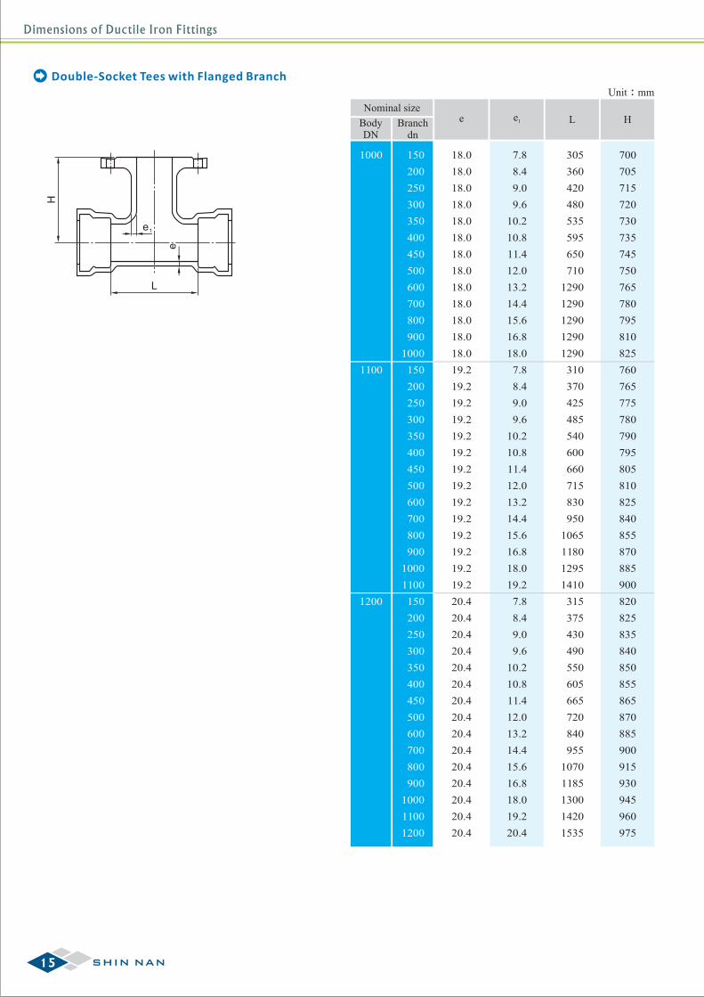
Dimensions of Ductile Iron Fittings
Unit:mm
Nominal size
BodyDN
Branchdn
e e1 L H
1000
1100
1200
Double-Socket Tees with Flanged Branch
H
L
e1
e200
250
300
350
400
450
500
600
700
800
900
1000
150
200
250
300
350
400
450
500
600
700
800
900
1000
1100
150
200
250
300
350
400
450
500
600
700
800
900
1000
1100
1200
150 18.0
18.0
18.0
18.0
18.0
18.0
18.0
18.0
18.0
18.0
18.0
18.0
18.0
19.2
19.2
19.2
19.2
19.2
19.2
19.2
19.2
19.2
19.2
19.2
19.2
19.2
19.2
20.4
20.4
20.4
20.4
20.4
20.4
20.4
20.4
20.4
20.4
20.4
20.4
20.4
20.4
20.4
7.8
8.4
9.0
9.6
10.2
10.8
11.4
12.0
13.2
14.4
15.6
16.8
18.0
7.8
8.4
9.0
9.6
10.2
10.8
11.4
12.0
13.2
14.4
15.6
16.8
18.0
19.2
7.8
8.4
9.0
9.6
10.2
10.8
11.4
12.0
13.2
14.4
15.6
16.8
18.0
19.2
20.4
305
360
420
480
535
595
650
710
1290
1290
1290
1290
1290
310
370
425
485
540
600
660
715
830
950
1065
1180
1295
1410
315
375
430
490
550
605
665
720
840
955
1070
1185
1300
1420
1535
700
705
715
720
730
735
745
750
765
780
795
810
825
760
765
775
780
790
795
805
810
825
840
855
870
885
900
820
825
835
840
850
855
865
870
885
900
915
930
945
960
975
15 SHIN NAN
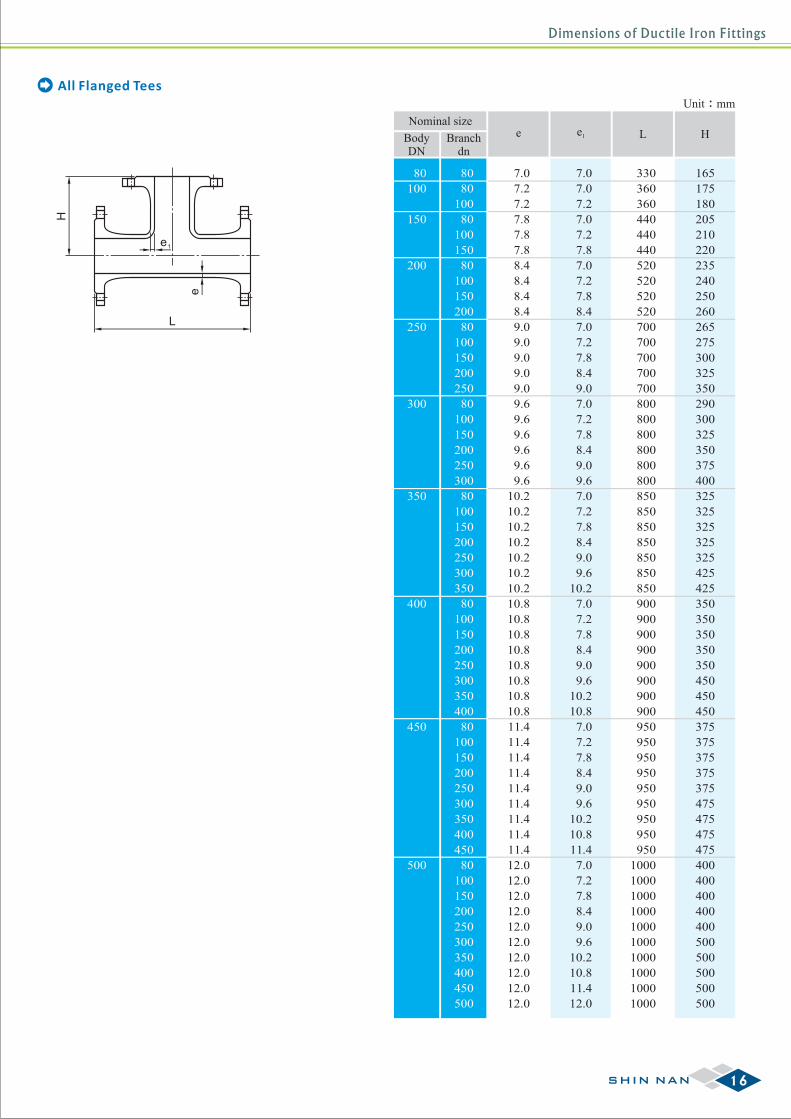
Dimensions of Ductile Iron Fittings
L
H
e1
e
80
100
150
200
250
300
350
400
450
500
80
80
100
80
100
150
80
100
150
200
80
100
150
200
250
80
100
150
200
250
300
80
100
150
200
250
300
350
80
100
150
200
250
300
350
400
80
100
150
200
250
300
350
400
450
80
100
150
200
250
300
350
400
450
500
7.0
7.2
7.2
7.8
7.8
7.8
8.4
8.4
8.4
8.4
9.0
9.0
9.0
9.0
9.0
9.6
9.6
9.6
9.6
9.6
9.6
10.2
10.2
10.2
10.2
10.2
10.2
10.2
10.8
10.8
10.8
10.8
10.8
10.8
10.8
10.8
11.4
11.4
11.4
11.4
11.4
11.4
11.4
11.4
11.4
12.0
12.0
12.0
12.0
12.0
12.0
12.0
12.0
12.0
12.0
7.0
7.0
7.2
7.0
7.2
7.8
7.0
7.2
7.8
8.4
7.0
7.2
7.8
8.4
9.0
7.0
7.2
7.8
8.4
9.0
9.6
7.0
7.2
7.8
8.4
9.0
9.6
10.2
7.0
7.2
7.8
8.4
9.0
9.6
10.2
10.8
7.0
7.2
7.8
8.4
9.0
9.6
10.2
10.8
11.4
7.0
7.2
7.8
8.4
9.0
9.6
10.2
10.8
11.4
12.0
330
360
360
440
440
440
520
520
520
520
700
700
700
700
700
800
800
800
800
800
800
850
850
850
850
850
850
850
900
900
900
900
900
900
900
900
950
950
950
950
950
950
950
950
950
1000
1000
1000
1000
1000
1000
1000
1000
1000
1000
165
175
180
205
210
220
235
240
250
260
265
275
300
325
350
290
300
325
350
375
400
325
325
325
325
325
425
425
350
350
350
350
350
450
450
450
375
375
375
375
375
475
475
475
475
400
400
400
400
400
500
500
500
500
500
Unit:mm
Nominal size
BodyDN
Branchdn
e e1 L H
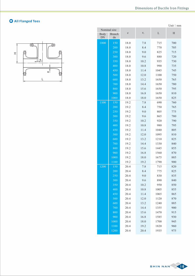
All Flanged Tees
16SHIN NAN
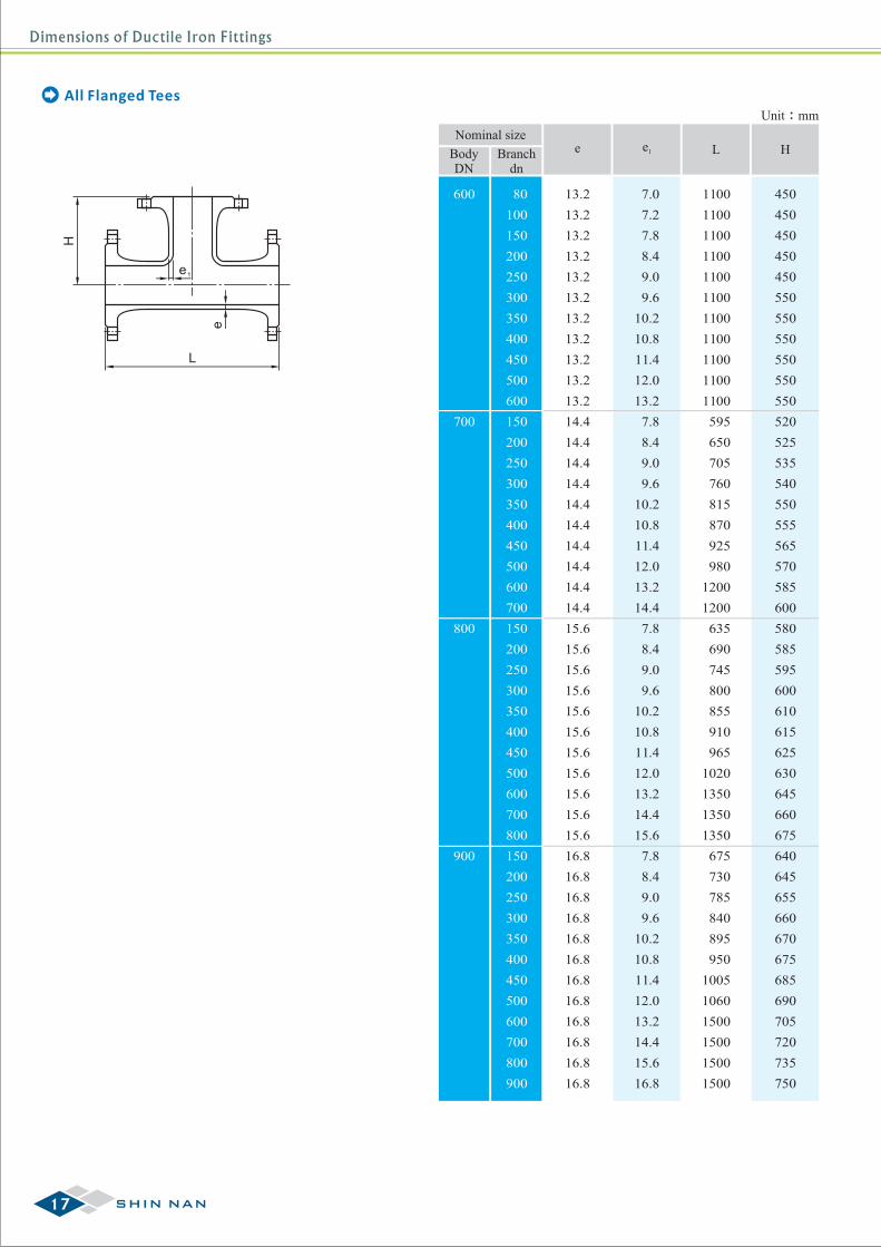
Dimensions of Ductile Iron Fittings
Unit:mm
Nominal size
BodyDN
Branchdn
600
700
800
900
80
100
150
200
250
300
350
400
450
500
600
150
200
250
300
350
400
450
500
600
700
150
200
250
300
350
400
450
500
600
700
800
150
200
250
300
350
400
450
500
600
700
800
900
e e1 L H
13.2
13.2
13.2
13.2
13.2
13.2
13.2
13.2
13.2
13.2
13.2
14.4
14.4
14.4
14.4
14.4
14.4
14.4
14.4
14.4
14.4
15.6
15.6
15.6
15.6
15.6
15.6
15.6
15.6
15.6
15.6
15.6
16.8
16.8
16.8
16.8
16.8
16.8
16.8
16.8
16.8
16.8
16.8
16.8
7.0
7.2
7.8
8.4
9.0
9.6
10.2
10.8
11.4
12.0
13.2
7.8
8.4
9.0
9.6
10.2
10.8
11.4
12.0
13.2
14.4
7.8
8.4
9.0
9.6
10.2
10.8
11.4
12.0
13.2
14.4
15.6
7.8
8.4
9.0
9.6
10.2
10.8
11.4
12.0
13.2
14.4
15.6
16.8
1100
1100
1100
1100
1100
1100
1100
1100
1100
1100
1100
595
650
705
760
815
870
925
980
1200
1200
635
690
745
800
855
910
965
1020
1350
1350
1350
675
730
785
840
895
950
1005
1060
1500
1500
1500
1500
450
450
450
450
450
550
550
550
550
550
550
520
525
535
540
550
555
565
570
585
600
580
585
595
600
610
615
625
630
645
660
675
640
645
655
660
670
675
685
690
705
720
735
750
All Flanged Tees
L
H
e1
e
17 SHIN NAN
Dimensions of Ductile Iron Fittings
Unit:mm
Nominal size
BodyDN
Branchdn
e e1 L H
1000
1100
1200
200
250
300
350
400
450
500
600
700
800
900
1000
150
200
250
300
350
400
450
500
600
700
800
900
1000
1100
150
200
250
300
350
400
450
500
600
700
800
900
1000
1100
1200
150 18.0
18.0
18.0
18.0
18.0
18.0
18.0
18.0
18.0
18.0
18.0
18.0
18.0
19.2
19.2
19.2
19.2
19.2
19.2
19.2
19.2
19.2
19.2
19.2
19.2
19.2
19.2
20.4
20.4
20.4
20.4
20.4
20.4
20.4
20.4
20.4
20.4
20.4
20.4
20.4
20.4
20.4
7.8
8.4
9.0
9.6
10.2
10.8
11.4
12.0
13.2
14.4
15.6
16.8
18.0
7.8
8.4
9.0
9.6
10.2
10.8
11.4
12.0
13.2
14.4
15.6
16.8
18.0
19.2
7.8
8.4
9.0
9.6
10.2
10.8
11.4
12.0
13.2
14.4
15.6
16.8
18.0
19.2
20.4
715
770
825
880
935
990
1045
1100
1650
1650
1650
1650
1650
690
750
805
865
920
980
1040
1095
1210
1330
1445
1560
1675
1790
715
775
830
890
950
1005
1065
1120
1240
1355
1470
1585
1700
1820
1935
700
705
715
720
730
735
745
750
765
780
795
810
825
760
765
775
780
790
795
805
810
825
840
855
870
885
900
820
825
835
840
850
855
865
870
885
900
915
930
945
960
975
All Flanged Tees
L
H
e1
e
18SHIN NAN
Dimensions of Ductile Iron Fittings
e
1e
L
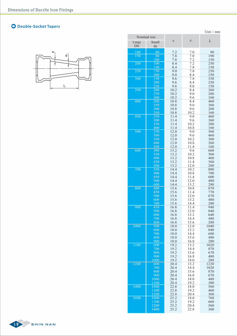
Unit:mm
Nominal size
100150
200
250
300
350
400
450
500
600
700
800
900
1000
1100
1200
1400
1600
8080
100100150150200150200250200250300200250300350250300350400250300350400450300350400450500350400450500600400450500600700450500600700800500600700800900600700800900
1000600700800900
100011001000110012001000110012001400
7.27.87.88.48.49.09.09.69.69.6
10.210.210.210.810.810.810.811.411.411.411.412.012.012.012.012.013.213.213.213.213.214.414.414.414.414.415.615.615.615.615.616.816.816.816.816.818.018.018.018.018.019.219.219.219.219.220.420.420.420.420.420.422.822.822.825.225.225.225.2
7.07.07.27.27.87.88.47.88.49.08.49.09.68.49.09.6
10.29.09.6
10.210.8
9.09.6
10.210.811.49.6
10.210.811.412.010.210.811.412.013.210.811.412.013.214.411.412.013.214.415.612.013.214.415.616.813.214.415.616.818.013.214.415.616.818.019.218.019.220.418.019.220.422.8
90190150250150250150350250150360260160460360260160460360260160560460360260160660560460360260800700600480280870770670480280940840640480280
1040840680480280
1020870670480280
12201020870670480300560460360760660560360
LargeDN
Smalldn
e e1 L
Double-Socket Tapers
19 SHIN NAN
Dimensions of Ductile Iron Fittings
g
DC
P
Dba
d
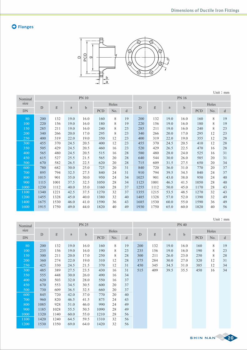
Flanges
Unit:mm
Nominalsize
DND Dg ga ab b
PCD PCDNo. No.
Holes Holes
PN 25 PN 40
80
100
150
200
250
300
350
400
450
500
600
700
800
900
1000
1100
1200
200
235
300
360
425
485
555
620
670
730
845
960
1085
1185
1320
1420
1530
132
156
211
274
330
389
448
503
553
609
720
820
928
1028
1140
1240
1350
19.0
19.0
20.0
22.0
24.5
27.5
30.0
32.0
34.5
36.5
42.0
46.5
51.0
55.5
60.0
64.5
69.0
16.0
16.0
17.0
19.0
21.5
23.5
26.0
28.0
30.5
32.5
37.0
41.5
46.0
50.5
55.0
59.5
64.0
160
190
250
310
370
430
490
550
600
660
770
875
990
1090
1210
1310
1420
8
8
8
12
12
16
16
16
20
20
20
24
24
28
28
32
32
19
23
28
28
31
31
34
37
37
37
40
43
49
49
56
56
56
200
235
300
375
450
515
132
156
211
284
345
409
19.0
19.0
26.0
30.0
34.5
39.5
16.0
16.0
23.0
27.0
31.0
35.5
160
190
250
320
385
450
8
8
8
12
12
16
19
23
28
31
34
34
dd
Unit:mm
Nominalsize
DND Dg ga ab b
PCD PCDNo. No.d
Holes Holes
PN 10 PN 16
80
100
150
200
250
300
350
400
450
500
600
700
800
900
1000
1100
1200
1400
1600
200
220
285
340
400
455
505
565
615
670
780
895
1015
1115
1230
1340
1455
1675
1915
132
156
211
266
319
370
429
480
527
582
682
794
901
1001
1112
1221
1328
1530
1750
19.0
19.0
19.0
20.0
22.0
24.5
24.5
24.5
25.5
26.5
30.0
32.5
35.0
37.5
40.0
42.5
45.0
46.0
49.0
16.0
16.0
16.0
17.0
19.0
20.5
20.5
20.5
21.5
22.5
25.0
27.5
30.0
32.5
35.0
37.5
40.0
41.0
44.0
160
180
240
295
350
400
460
515
565
620
725
840
950
1050
1160
1270
1380
1590
1820
8
8
8
8
12
12
16
16
20
20
20
24
24
28
28
32
32
36
40
19
19
23
23
23
23
23
28
28
28
31
31
34
34
37
37
40
43
49
200
220
285
340
400
455
520
580
640
715
840
910
1025
1125
1255
1355
1485
1685
1930
132
156
211
266
319
370
429
480
544
609
720
794
901
1001
1112
1215
1328
1530
1750
19.0
19.0
19.0
20.0
22.0
24.5
26.5
28.0
30.0
31.5
36.0
39.5
43.0
46.5
50.0
53.5
57.0
60.0
65.0
16.0
16.0
16.0
17.0
19.0
20.5
22.5
24.0
26.0
27.5
31.0
34.5
38.0
41.5
45.0
48.5
52.0
55.0
60.0
160
180
240
295
355
410
470
525
585
650
770
840
950
1050
1170
1270
1390
1590
1820
8
8
8
12
12
12
16
16
20
20
20
24
24
28
28
32
32
36
40
19
19
23
23
28
28
28
31
31
34
37
37
40
40
43
43
49
49
56
d
20SHIN NAN
Dimensions of Ductile Iron Fittings
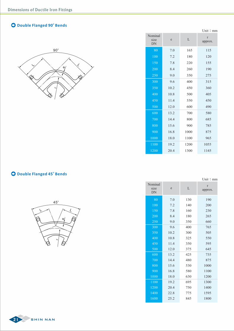
oDouble Flanged 90 Bends
oDouble Flanged 45 Bends
o90
L Le
r
LL
e
o45
r
Unit:mm
NominalsizeDN
80
100
150
200
250
300
350
400
450
500
600
700
800
900
1000
1100
1200
e L
7.0
7.2
7.8
8.4
9.0
9.6
10.2
10.8
11.4
12.0
13.2
14.4
15.6
16.8
18.0
19.2
20.4
165
180
220
260
350
400
450
500
550
600
700
800
900
1000
1100
1200
1300
rapprox.
115
120
155
190
275
315
360
405
450
490
580
685
785
875
965
1055
1145
Unit:mm
NominalsizeDN
80
100
150
200
250
300
350
400
450
500
600
700
800
900
1000
1100
1200
1400
1600
e L
7.0
7.2
7.8
8.4
9.0
9.6
10.2
10.8
11.4
12.0
13.2
14.4
15.6
16.8
18.0
19.2
20.4
22.8
25.2
130
140
160
180
350
400
300
325
350
375
425
480
530
580
630
695
750
775
845
rapprox.
190
200
230
265
660
765
505
550
595
645
735
875
1000
1100
1200
1300
1400
1595
1800
21 SHIN NAN
Dimensions of Ductile Iron Fittings
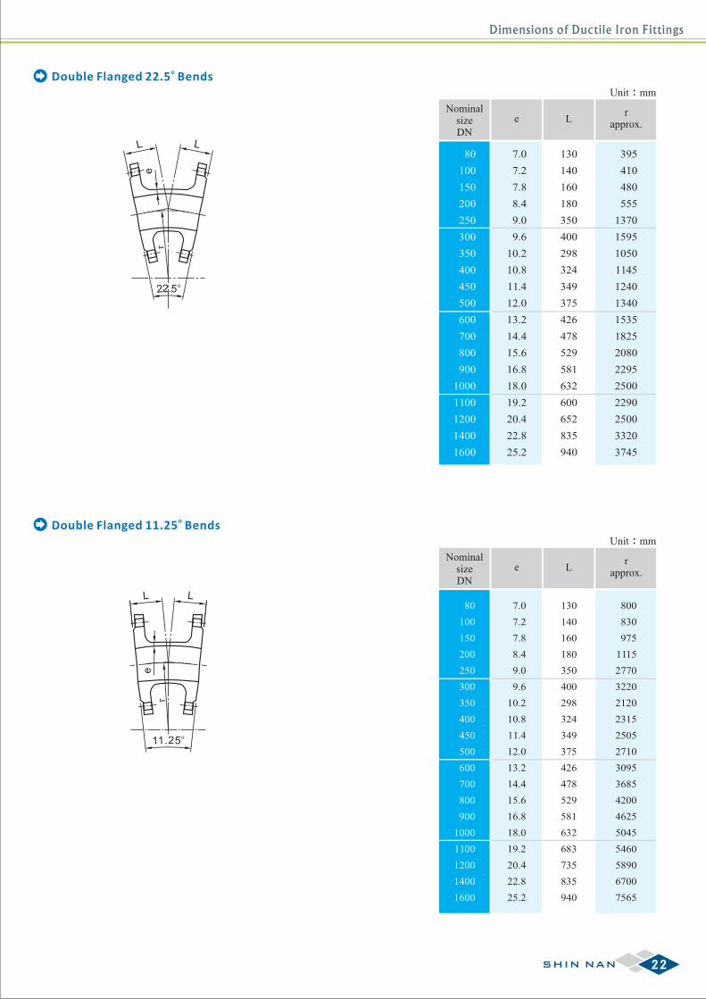
oDouble Flanged 22.5 Bends
L
o2.52
Le
r
L
e
L
o.2511
r
oDouble Flanged 11.25 Bends
Unit:mm
NominalsizeDN
80
100
150
200
250
300
350
400
450
500
600
700
800
900
1000
1100
1200
1400
1600
e L
7.0
7.2
7.8
8.4
9.0
9.6
10.2
10.8
11.4
12.0
13.2
14.4
15.6
16.8
18.0
19.2
20.4
22.8
25.2
130
140
160
180
350
400
298
324
349
375
426
478
529
581
632
600
652
835
940
rapprox.
395
410
480
555
1370
1595
1050
1145
1240
1340
1535
1825
2080
2295
2500
2290
2500
3320
3745
Unit:mm
NominalsizeDN
80
100
150
200
250
300
350
400
450
500
600
700
800
900
1000
1100
1200
1400
1600
e L
7.0
7.2
7.8
8.4
9.0
9.6
10.2
10.8
11.4
12.0
13.2
14.4
15.6
16.8
18.0
19.2
20.4
22.8
25.2
130
140
160
180
350
400
298
324
349
375
426
478
529
581
632
683
735
835
940
rapprox.
800
830
975
1115
2770
3220
2120
2315
2505
2710
3095
3685
4200
4625
5045
5460
5890
6700
7565
22SHIN NAN
Dimensions of Ductile Iron Fittings
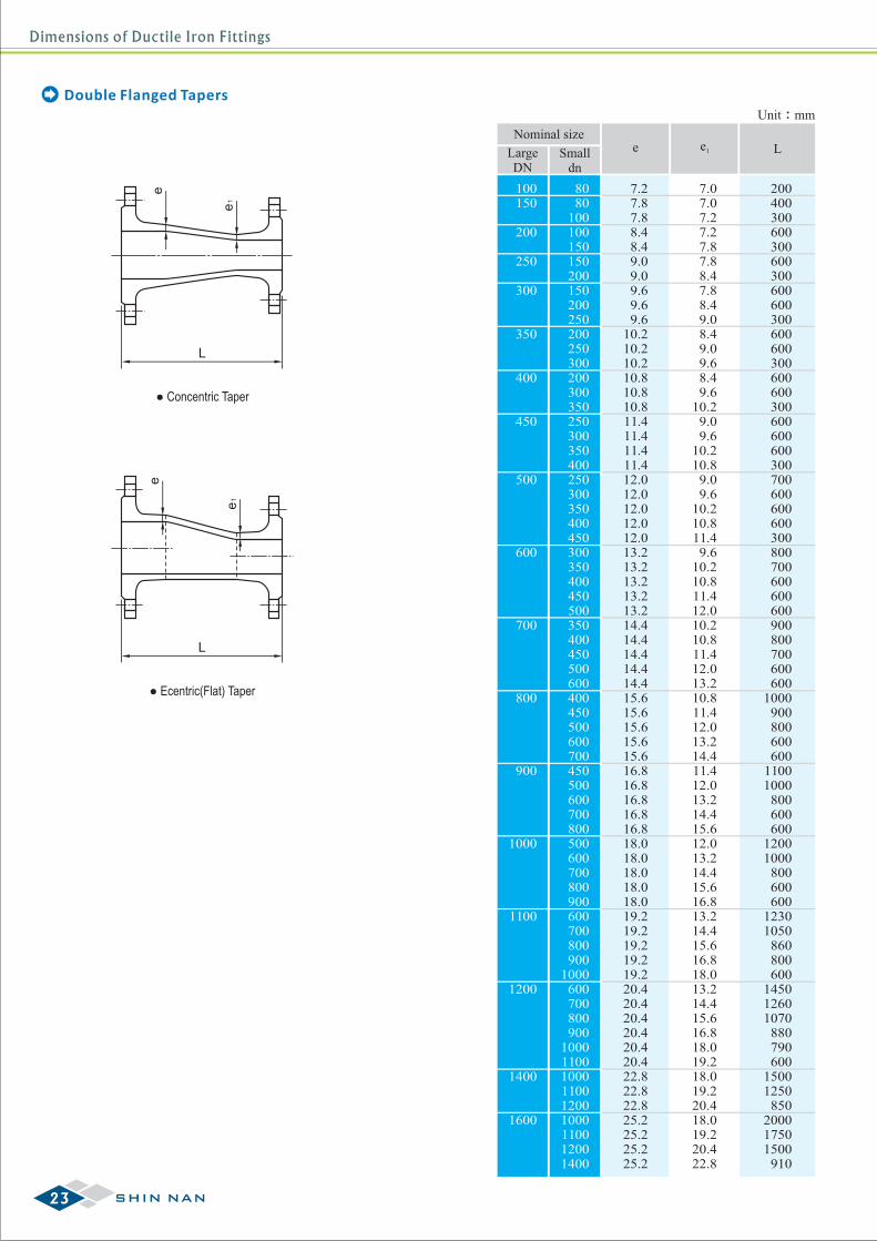
Double Flanged TapersUnit:mm
Nominal size
LargeDN
Smalldn
e e1 L
100150
200
250
300
350
400
450
500
600
700
800
900
1000
1100
1200
1400
1600
200400300600300600300600600300600600300600600300600600600300700600600600300800700600600600900800700600600
1000900800600600
11001000800600600
12001000800600600
12301050860800600
145012601070880790600
15001250850
200017501500910
8080
100100150150200150200250200250300200300350250300350400250300350400450300350400450500350400450500600400450500600700450500600700800500600700800900600700800900
1000600700800900
100011001000110012001000110012001400
7.27.87.88.48.49.09.09.69.69.6
10.210.210.210.810.810.811.411.411.411.412.012.012.012.012.013.213.213.213.213.214.414.414.414.414.415.615.615.615.615.616.816.816.816.816.818.018.018.018.018.019.219.219.219.219.220.420.420.420.420.420.422.822.822.825.225.225.225.2
7.07.07.27.27.87.88.47.88.49.08.49.09.68.49.6
10.29.09.6
10.210.89.09.6
10.210.811.49.6
10.210.811.412.010.210.811.412.013.210.811.412.013.214.411.412.013.214.415.612.013.214.415.616.813.214.415.616.818.013.214.415.616.818.019.218.019.220.418.019.220.422.8
L
e
1e
● Concentric Taper
L
e
1e
● Ecentric(Flat) Taper
23 SHIN NAN

Dimensions of Ductile Iron Fittings
oDouble Flanged 90 Duckfoot Bends
Unit:mm
NominalsizeDN
80
100
150
200
250
300
350
400
450
500
600
700
800
900
1000
1100
1200
1400
1600
e L
7.0
7.2
7.8
8.4
9.0
9.6
10.2
10.8
11.4
12.0
13.2
14.4
15.6
16.8
18.0
19.2
20.4
22.8
25.2
135
140
155
170
190
210
225
245
260
280
300
340
380
420
440
465
490
515
540
B R
80
85
95
110
120
135
145
160
170
185
210
225
240
255
270
285
300
305
310
100
106
119
137
150
169
181
200
212
231
262
281
300
319
337
357
376
400
400
D
160
185
245
310
370
435
495
560
620
685
810
945
1055
1165
1290
1400
1515
1725
1945
L
e
R
B
D
Flange Bellmouths
b
bc
d square
o
90
r e
Unit:mm
NominalsizeDN
80
100
150
200
250
300
350
400
450
500
600
700
800
900
1000
1100
1200
e
7.0
7.2
7.8
8.4
9.0
9.6
10.2
10.8
11.4
12.0
13.2
14.4
15.6
16.8
18.0
19.2
20.4
cd
180
200
250
300
350
400
450
500
550
600
700
800
900
1000
1100
1200
1300
rapprox.
115
120
155
190
275
315
360
405
450
490
580
685
785
875
965
1055
1145
b
165
180
220
260
350
400
450
500
550
600
700
800
900
1000
1100
1200
1300
110
125
160
190
225
255
290
320
355
385
450
515
580
645
710
775
840
24SHIN NAN
Dimensions of Ductile Iron Fittings
Le
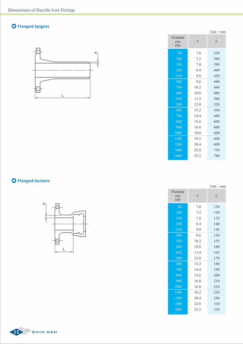
Flanged Spigots
e
L
Flanged Sockets
Unit:mm
NominalsizeDN
80
100
150
200
250
300
350
400
450
500
600
700
800
900
1000
1100
1200
1400
1600
e L
7.0
7.2
7.8
8.4
9.0
9.6
10.2
10.8
11.4
12.0
13.2
14.4
15.6
16.8
18.0
19.2
20.4
22.8
25.2
350
360
380
400
420
440
460
480
500
520
560
600
600
600
600
600
600
710
780
Unit:mm
NominalsizeDN
80
100
150
200
250
300
350
400
450
500
600
700
800
900
1000
1100
1200
1400
1600
e L
7.0
7.2
7.8
8.4
9.0
9.6
10.2
10.8
11.4
12.0
13.2
14.4
15.6
16.8
18.0
19.2
20.4
22.8
25.2
130
130
135
140
145
150
155
160
165
170
180
190
200
210
220
230
240
310
330
25 SHIN NAN
Dimensions of Ductile Iron Fittings
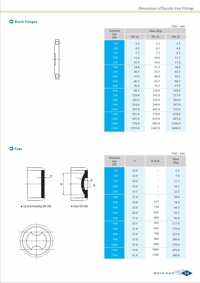
Blank Flanges
Caps
Unit:mm
NominalsizeDN
80
100
150
200
250
300
350
400
450
500
600
700
800
900
1000
1100
1200
1400
1600
3.5
4.3
7.2
11.0
16.9
24.0
30.5
37.5
46.5
58.0
88.5
128.0
180.0
234.0
307.0
391.0
491.0
739.0
1239.0
3.5
4.3
7.2
10.8
16.6
23.5
34.5
46.0
63.5
79.5
125.0
163.0
228.0
299.0
405.0
518.0
635.0
993.0
1462.0
3.5
4.8
8.3
13.3
21.0
30.0
44.5
59.5
80.5
97.0
149.0
215.0
304.0
397.0
535.0
670.0
843.0
1196.0
1668.0
Mass (Kg)
PN 10 PN 16 PN 25
Unit:mm
NominalsizeDN
80
100
150
200
250
300
350
400
450
500
600
700
800
900
1000
1100
1200
18.0
18.0
18.0
18.0
19.5
23.0
24.0
25.0
26.0
27.0
29.5
31.0
33.0
35.0
37.0
39.0
41.0
6.2
7.0
11.3
16.1
22.5
38.0
54.0
68.5
83.5
96.0
117.0
170.0
225.0
300.0
370.0
470.0
580.0
-
-
-
-
-
-
315
370
420
460
565
665
760
860
960
1060
1160
e K & RMass(Kg)
e
● Up to & including DN 300
e
R
K
● Over DN 300
26SHIN NAN

Dimensions of Ductile Iron Fittings
L
ed
Unit:mm
NominalsizeDN
80
100
150
200
250
300
350
400
500
600
700
800
900
1000
1200
1400
1600
1800
2000
e
7.0
7.2
7.8
8.4
9.0
9.6
10.2
10.8
12.0
13.2
14.4
15.6
16.8
18.0
20.4
22.8
25.2
27.6
30.0
109
130
183
235
288
340
393
445
550
655
760
865
970
1075
1285
1477
1683
1889
2095
160
160
165
170
175
180
185
190
200
210
220
230
240
250
270
340
360
380
400
d L
Collars
27 SHIN NAN
Pipe Jointing & Assembly
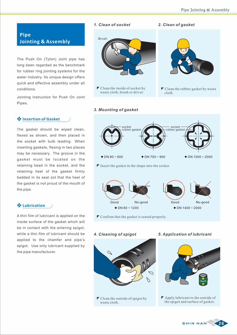
3. Mounting of gasket
zInsert the gasket in the shape into the socket.
socketrubber gasket
socketrubber gasket
l DN 80 ~ 600 l DN 700 ~ 900 l DN 1000 ~ 2000
zConfirm that the gasket is seated properly.
Good No-good
l DN 80 ~ 1200
Good No-good
l DN 1400 ~ 2000
4. Cleaning of spigot
zClean the outside of spigot by waste cloth.
LU TB NRICA
5. Application of lubricant
zApply lubricant to the outside of the spigot and surface of gasket.
2. Clean of gasket
zClean the rubber gasket by waste cloth.
1. Clean of socket
zClean the inside of socket by waste cloth, brush or driver.
BrushPipeJointing & Assembly
The Push On (Tyton) Joint pipe has
long been regarded as the benchmark
for rubber ring jointing systems for the
water industry. Its unique design offers
quick and effective assembly under all
conditions.
Jointing instruction for Push On Joint
Pipes.
Insertion of Gasket
The gasket should be wiped clean,
flexed as shown, and then placed in
the socket with bulb leading. When
inserting gaskets, flexing in two places
may be necessary. The groove in the
gaske t mus t be l oca ted on the
retaining bead in the socket, and the
retaining heel of the gasket firmly
bedded in its seat sot that the heel of
the gasket is not proud of the mouth of
the pipe.
Lubrication
A thin film of lubricant is applied on the
inside surface of the gasket which will
be in contact with the entering spigot,
while a thin film of lubricant should be
applied to the chamfer and pipe’s
spigot. Use only lubricant supplied by
the pipe manufacturer.
28SHIN NAN
Pipe Jointing & Assembly
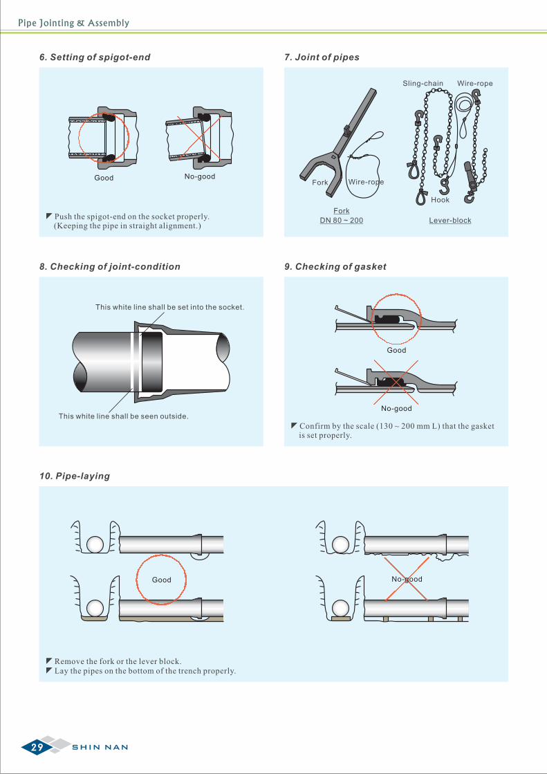
8. Checking of joint-condition
This white line shall be set into the socket.
This white line shall be seen outside.
9. Checking of gasket
Good
No-good
zConfirm by the scale (130 ~ 200 mm L) that the gasket is set properly.
10. Pipe-laying
Good No-good
zRemove the fork or the lever block.zLay the pipes on the bottom of the trench properly.
7. Joint of pipes
Wire-ropeFork
DN 80 ~ 200
Fork
Sling-chain Wire-rope
Hook
Lever-block
6. Setting of spigot-end
Good No-good
zPush the spigot-end on the socket properly. (Keeping the pipe in straight alignment.)
29 SHIN NAN
Pipe Jointing & Assembly
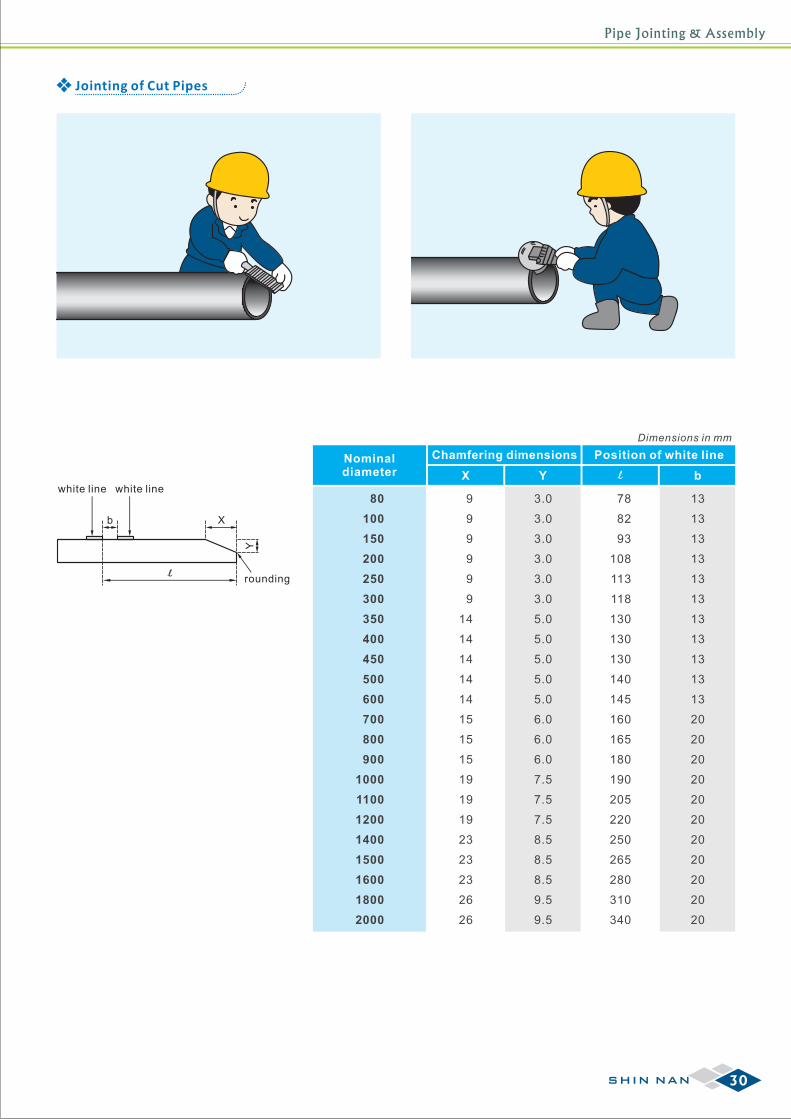
Jointing of Cut Pipes
white line white line
b X
Y
rounding
Nominaldiameter
80
100
150
200
250
300
350
400
450
500
600
700
800
900
1000
1100
1200
1400
1500
1600
1800
2000
X
9
9
9
9
9
9
14
14
14
14
14
15
15
15
19
19
19
23
23
23
26
26
Y b
Chamfering dimensions Position of white line
3.0
3.0
3.0
3.0
3.0
3.0
5.0
5.0
5.0
5.0
5.0
6.0
6.0
6.0
7.5
7.5
7.5
8.5
8.5
8.5
9.5
9.5
78
82
93
108
113
118
130
130
130
140
145
160
165
180
190
205
220
250
265
280
310
340
13
13
13
13
13
13
13
13
13
13
13
20
20
20
20
20
20
20
20
20
20
20
Dimensions in mm
30SHIN NAN
Pipe Handling Recommendations
PipeHandling Recommendations
Ductile Iron Pipes are not susceptible to breakage by
impact loading, but bad handling can result in damages
to linings and in severe situation to bruising and
deformation of the spigot which could affect the sealing
of the joint when install.
Damage to pipes and joint components may be caused
by the following:
1. Insecure loading on truck or vehicle
2. Improper use of handling equipments
3. Incorrect stacking or storing methods
4. Improper storing of jointing components
5. Unloading on uneven or sloping ground
Damage can be avoided by paying attention to the
following points:
Transportation
All pipes must be secured with steel wire rope to the
truck to prevent movement during transport. Suitable
protection such as rubber or carpet should be placed
between the wire rope and the outer pipes of the top
row.
The use of straight sided loading allows full advantage
to be taken of the carrying capacity of the vehicle. Pipes
should be loaded onto vehicles using scalloped
hardwood timbers of sufficient thickness to ensure no
metal to metal contact occurs between rows of pipes.
On receipt of pipes, it should be inspected of
damages to:
a. The Pipe itself
b. Cement mortar linings
c. Jointing surfaces (Socket area)
And proposed remedial work shall be undertaken
(whenever require) as soon as possible.
Inspection
Unloading
Pipe masses, type of stacking, outreach required
and the site conditions are the important factors to
take into account when determining the suitability of
lifting equipment. The machine used must be of the
type which retains the load safely in the event of a
power failure.
Offloading by Crane
Lifting Operat ion
It is necessary when using mechanical handling
equipment to employ experienced and qualified
personnel to carry out the operation efficiently and
safely.
Where the crane operator does not have a clear view
of the load, he should be guided by the person
supervising the operation. The pipes should be lifted
smoothly, without sudden jerking motions, and pipe
movement should be controlled by the use of guide
ropes. This is necessary for safety and also to
prevent damage caused by pipes bumping together
or against surrounding objects.
Lifting and placing must be carried out in such a way
that the stability of the stack, crane of vehicle is not
affected. Steel wire rope securing the pipes to the
truck should not be released before ensuring the
truck is positioned on level ground.
31 SHIN NAN
Pipe Installation & Joint Assembly Method
Timber beader
Pipe Installation &Joint Assembly Method
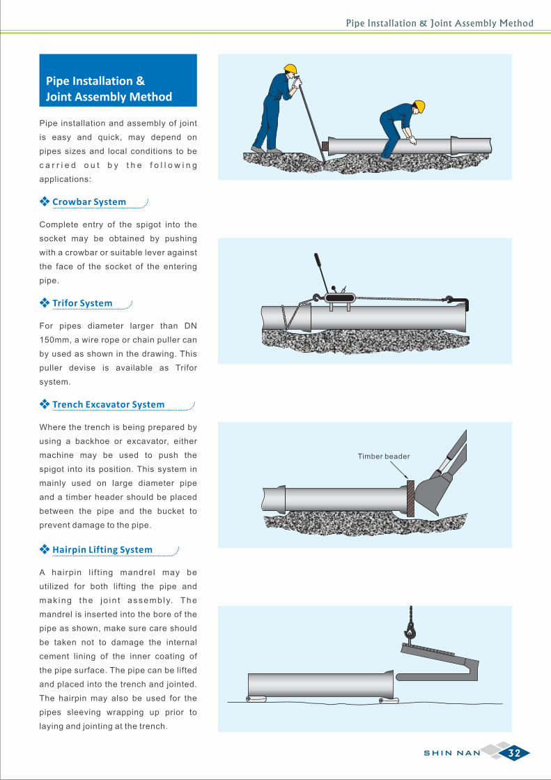
Pipe installation and assembly of joint
is easy and quick, may depend on
pipes sizes and local conditions to be
c a r r i e d o u t b y t h e f o l l o w i n g
applications:
Crowbar System
Complete entry of the spigot into the
socket may be obtained by pushing
with a crowbar or suitable lever against
the face of the socket of the entering
pipe.
Trifor System
For pipes diameter larger than DN
150mm, a wire rope or chain puller can
by used as shown in the drawing. This
puller devise is available as Trifor
system.
Trench Excavator System
Where the trench is being prepared by
using a backhoe or excavator, either
machine may be used to push the
spigot into its position. This system in
mainly used on large diameter pipe
and a timber header should be placed
between the pipe and the bucket to
prevent damage to the pipe.
Hairpin Lifting System
A hairpin l i f t ing mandrel may be
utilized for both lifting the pipe and
mak ing the jo in t assemb ly. The
mandrel is inserted into the bore of the
pipe as shown, make sure care should
be taken not to damage the internal
cement lining of the inner coating of
the pipe surface. The pipe can be lifted
and placed into the trench and jointed.
The hairpin may also be used for the
pipes sleeving wrapping up prior to
laying and jointing at the trench.
32SHIN NAN
Corrosion Protection
Loose Tie Straps
Adhesive Tape
CorrosionProtection
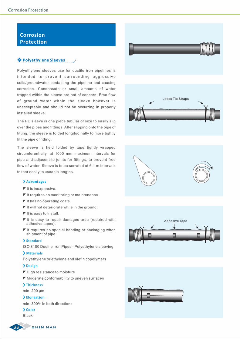
Polyethylene sleeves use for ductile iron pipelines is
i n t e n d e d t o p r e v e n t s u r r o u n d i n g a g g r e s s i v e
soils/groundwater contacting the pipeline and causing
corrosion. Condensate or small amounts of water
trapped within the sleeve are not of concern. Free flow
of ground water wi th in the s leeve however is
unacceptable and should not be occurring in properly
installed sleeve.
The PE sleeve is one piece tubular of size to easily slip
over the pipes and fittings. After slipping onto the pipe of
fitting, the sleeve is folded longitudinally to more tightly
fit the pipe of fitting.
The sleeve is held folded by tape tightly wrapped
circumferentially, at 1000 mm maximum intervals for
pipe and adjacent to joints for fittings, to prevent free
flow of water. Sleeve is to be serrated at 6.1 m intervals
to tear easily to useable lengths.
Polyethylene Sleeves
zIt is inexpensive.
zIt requires no monitoring or maintenance.
zIt has no operating costs.
zIt will not deteriorate while in the ground.
zIt is easy to install.
zIt is easy to repair damages area (repaired with adhesive tapes).
zIt requires no special handing or packaging when shipment of pipe.
Advantages
Standard
Mate rials
Design
Thickness
Elongat ion
Color
ISO 8180 Ductile Iron Pipes - Polyethylene sleeving
Polyethylene or ethylene and olefin copolymers
zHigh resistance to moisture
zModerate conformability to uneven surfaces
min. 200 µm
min. 300% in both directions
Black
33 SHIN NAN
Pipeline PE Sleeving Installation
Pipeline PESleeving Installation
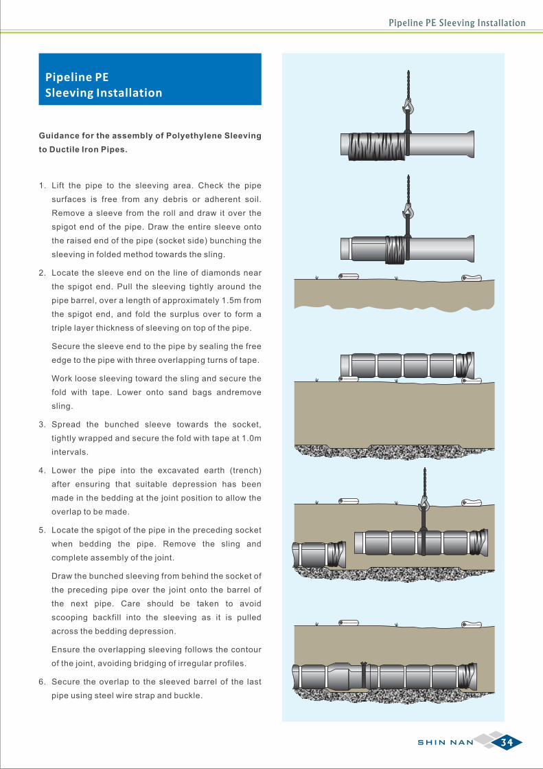
1. Lift the pipe to the sleeving area. Check the pipe
surfaces is free from any debris or adherent soil.
Remove a sleeve from the roll and draw it over the
spigot end of the pipe. Draw the entire sleeve onto
the raised end of the pipe (socket side) bunching the
sleeving in folded method towards the sling.
2. Locate the sleeve end on the line of diamonds near
the spigot end. Pull the sleeving tightly around the
pipe barrel, over a length of approximately 1.5m from
the spigot end, and fold the surplus over to form a
triple layer thickness of sleeving on top of the pipe.
Secure the sleeve end to the pipe by sealing the free
edge to the pipe with three overlapping turns of tape.
Work loose sleeving toward the sling and secure the
fold with tape. Lower onto sand bags andremove
sling.
3. Spread the bunched sleeve towards the socket,
tightly wrapped and secure the fold with tape at 1.0m
intervals.
4. Lower the pipe into the excavated earth (trench)
after ensuring that suitable depression has been
made in the bedding at the joint position to allow the
overlap to be made.
5. Locate the spigot of the pipe in the preceding socket
when bedding the pipe. Remove the sling and
complete assembly of the joint.
Draw the bunched sleeving from behind the socket of
the preceding pipe over the joint onto the barrel of
the next pipe. Care should be taken to avoid
scooping backfill into the sleeving as it is pulled
across the bedding depression.
Ensure the overlapping sleeving follows the contour
of the joint, avoiding bridging of irregular profiles.
6. Secure the overlap to the sleeved barrel of the last
pipe using steel wire strap and buckle.
Guidance for the assembly of Polyethylene Sleeving
to Ductile Iron Pipes.
34SHIN NAN

SHIN NANSHIN NAN CASTING FACTORY CO., LTD.
http://www.snpipe.com e-mail:[email protected]
435, Kung Yuan Road, Tainan City 70462, Taiwan, R.O.C.Tel:+886-6-2513646 Fax:+886-6-2514898
Head Office
19, Lane 23, Yung Kang St., Taipei City 10650, Taiwan, R.O.C.Tel:+886-2-23412580 Fax:+886-2-23943355
Taipei Office
72, Jou Wei St., Yen Jou Li, Yung Kang District, Tainan City 71044, Taiwan, R.O.C.Tel:+886-6-2534185 Fax:+886-6-2533554
Yung Kang Plant
90, Pei Shu Jou, Ming Ho Li, Shan Shang District, Tainan City 74342, Taiwan, R.O.C.Tel:+886-6-5781940 Fax:+886-6-5781915
Sun Shine Plant
2014.05 Ⓒ SHIN NAN CASTING FACTORY CO., L TD.


