Duet: Cloud Scale Load Balancing with Hardware and Software Rohan Gandhi † Hongqiang Harry Liu ∧ Y. Charlie Hu † Guohan Lu ? Jitendra Padhye ? Lihua Yuan ? Ming Zhang ? Microsoft ? , Purdue University † , Yale University ∧ ABSTRACT Load balancing is a foundational function of datacenter infrastruc- tures and is critical to the performance of online services hosted in datacenters. As the demand for cloud services grows, expen- sive and hard-to-scale dedicated hardware load balancers are being replaced with software load balancers that scale using a distributed data plane that runs on commodity servers. Software load balancers offer low cost, high availability and high flexibility, but suffer high latency and low capacity per load balancer, making them less than ideal for applications that demand either high throughput, or low la- tency or both. In this paper, we present DUET, which offers all the benefits of software load balancer, along with low latency and high availability – at next to no cost. We do this by exploiting a hith- erto overlooked resource in the data center networks – the switches themselves. We show how to embed the load balancing functional- ity into existing hardware switches, thereby achieving organic scal- ability at no extra cost. For flexibility and high availability, DUET seamlessly integrates the switch-based load balancer with a small deployment of software load balancer. We enumerate and solve several architectural and algorithmic challenges involved in build- ing such a hybrid load balancer. We evaluate DUET using a pro- totype implementation, as well as extensive simulations driven by traces from our production data centers. Our evaluation shows that DUET provides 10x more capacity than a software load balancer, at a fraction of a cost, while reducing latency by a factor of 10 or more, and is able to quickly adapt to network dynamics including failures. Categories and Subject Descriptors: C.2.4 [Computer- Communication Networks]: Distributed Systems—Network Oper- ating Systems General Terms: Design, Performance Keywords: Load Balancing, Datacenter, SDN 1. INTRODUCTION A high performance load balancer is one of the most important components of a cloud service infrastructure. Services in the data Permission to make digital or hard copies of all or part of this work for personal or classroom use is granted without fee provided that copies are not made or distributed for profit or commercial advantage and that copies bear this notice and the full cita- tion on the first page. Copyrights for components of this work owned by others than ACM must be honored. Abstracting with credit is permitted. To copy otherwise, or re- publish, to post on servers or to redistribute to lists, requires prior specific permission and/or a fee. Request permissions from [email protected]. SIGCOMM’14, August 17–22, 2014, Chicago, Illinois, USA. Copyright 2014 ACM 978-1-4503-2836-4/14/08 ...$15.00. http://dx.doi.org/10.1145/2619239.2626317 . center scale by running on multiple servers, each with an individ- ual direct IP (DIP). The service exposes one or more virtual IP addresses (VIP) outside the service boundary. The load balancer receives the traffic destined for the VIP, splits it among the DIPs, and routes it to the individual DIPs using IP-in-IP encapsulation. The load balancer thus touches every packet coming into the data center from the Internet, as well as a significant fraction of all intra-DC traffic. This traffic volume induces heavy load on both data plane and control plane of the load balancer [17]. The per- formance and reliability of the load balancer directly impact the latency, throughput and the availability of the cloud services hosted in the DC. Traditional load balancers are dedicated hardware middle- boxes [1, 4] that are very expensive. In contrast, Ananta [17] is a software load balancer that runs on commodity servers. Ananta consists of a central controller, and several software Muxes (SMux) that provide a distributed data plane. Each SMux maintains all VIP- to-DIP mappings, and implements traffic splitting and encapsula- tion functionality in software. The Ananta architecture is flexible, highly scalable and ensures high availability. However, software load balancers have two fundamental limita- tions, both of which stem from the fact that they process the packets in software. First, processing packets in software limits capacity. Experiments show that the CPU on individual Ananta SMux be- comes a bottleneck once the incoming traffic exceeds 300K packets per second. While the aggregate capacity of software load balancer can be scaled out by adding more servers, doing so raises cost. For example, handing 15Tbps traffic (typical for a mid-sized DC) re- quires over 4000 SMuxes, costing over USD 10 million. Second, processing packets in software incurs high, and highly variable latency. An Ananta SMux, handling as little as 100K packets per second can add anywhere from 200μsec to 1ms of la- tency. Applications such as algorithmic stock trading and high per- formance distributed memory caches demand ultra-low (a few mi- croseconds) latency within the data center. For such applications, the latency inflation by the software load balancer is not acceptable. In this paper, we propose DUET, which addresses these two drawbacks of software load balancers. DUET uses existing switch hardware in data centers to build a high performance, in-situ, organ- ically scalable hardware load balancer and seamlessly combines it with a small deployment of software load balancer for enhanced availability and flexibility. DUET is based on two key ideas. The first idea is to build a load balancer from existing switches in the data center network. The key insight is that the two core functions needed to imple- ment a load balancer – traffic splitting and packet encapsulation – have long been available in commodity switches deployed in data center networks. Traffic splitting is supported using ECMP, while
Transcript
Duet: Cloud Scale Load Balancing with Hardware andSoftware
Rohan Gandhi† Hongqiang Harry Liu∧ Y. Charlie Hu† Guohan Lu?
Jitendra Padhye? Lihua Yuan? Ming Zhang?
Microsoft?, Purdue University†, Yale University∧
ABSTRACTLoad balancing is a foundational function of datacenter infrastruc-tures and is critical to the performance of online services hostedin datacenters. As the demand for cloud services grows, expen-sive and hard-to-scale dedicated hardware load balancers are beingreplaced with software load balancers that scale using a distributeddata plane that runs on commodity servers. Software load balancersoffer low cost, high availability and high flexibility, but suffer highlatency and low capacity per load balancer, making them less thanideal for applications that demand either high throughput, or low la-tency or both. In this paper, we present DUET, which offers all thebenefits of software load balancer, along with low latency and highavailability – at next to no cost. We do this by exploiting a hith-erto overlooked resource in the data center networks – the switchesthemselves. We show how to embed the load balancing functional-ity into existing hardware switches, thereby achieving organic scal-ability at no extra cost. For flexibility and high availability, DUETseamlessly integrates the switch-based load balancer with a smalldeployment of software load balancer. We enumerate and solveseveral architectural and algorithmic challenges involved in build-ing such a hybrid load balancer. We evaluate DUET using a pro-totype implementation, as well as extensive simulations driven bytraces from our production data centers. Our evaluation shows thatDUET provides 10x more capacity than a software load balancer,at a fraction of a cost, while reducing latency by a factor of 10 ormore, and is able to quickly adapt to network dynamics includingfailures.
Categories and Subject Descriptors: C.2.4 [Computer-Communication Networks]: Distributed Systems—Network Oper-ating Systems
General Terms: Design, Performance
Keywords: Load Balancing, Datacenter, SDN
1. INTRODUCTIONA high performance load balancer is one of the most important
components of a cloud service infrastructure. Services in the data
Permission to make digital or hard copies of all or part of this work for personal orclassroom use is granted without fee provided that copies are not made or distributedfor profit or commercial advantage and that copies bear this notice and the full cita-tion on the first page. Copyrights for components of this work owned by others thanACM must be honored. Abstracting with credit is permitted. To copy otherwise, or re-publish, to post on servers or to redistribute to lists, requires prior specific permissionand/or a fee. Request permissions from [email protected]’14, August 17–22, 2014, Chicago, Illinois, USA.Copyright 2014 ACM 978-1-4503-2836-4/14/08 ...$15.00.http://dx.doi.org/10.1145/2619239.2626317.
center scale by running on multiple servers, each with an individ-ual direct IP (DIP). The service exposes one or more virtual IPaddresses (VIP) outside the service boundary. The load balancerreceives the traffic destined for the VIP, splits it among the DIPs,and routes it to the individual DIPs using IP-in-IP encapsulation.
The load balancer thus touches every packet coming into thedata center from the Internet, as well as a significant fraction ofall intra-DC traffic. This traffic volume induces heavy load on bothdata plane and control plane of the load balancer [17]. The per-formance and reliability of the load balancer directly impact thelatency, throughput and the availability of the cloud services hostedin the DC.
Traditional load balancers are dedicated hardware middle-boxes [1, 4] that are very expensive. In contrast, Ananta [17] isa software load balancer that runs on commodity servers. Anantaconsists of a central controller, and several software Muxes (SMux)that provide a distributed data plane. Each SMux maintains all VIP-to-DIP mappings, and implements traffic splitting and encapsula-tion functionality in software. The Ananta architecture is flexible,highly scalable and ensures high availability.
However, software load balancers have two fundamental limita-tions, both of which stem from the fact that they process the packetsin software. First, processing packets in software limits capacity.Experiments show that the CPU on individual Ananta SMux be-comes a bottleneck once the incoming traffic exceeds 300K packetsper second. While the aggregate capacity of software load balancercan be scaled out by adding more servers, doing so raises cost. Forexample, handing 15Tbps traffic (typical for a mid-sized DC) re-quires over 4000 SMuxes, costing over USD 10 million.
Second, processing packets in software incurs high, and highlyvariable latency. An Ananta SMux, handling as little as 100Kpackets per second can add anywhere from 200µsec to 1ms of la-tency. Applications such as algorithmic stock trading and high per-formance distributed memory caches demand ultra-low (a few mi-croseconds) latency within the data center. For such applications,the latency inflation by the software load balancer is not acceptable.
In this paper, we propose DUET, which addresses these twodrawbacks of software load balancers. DUET uses existing switchhardware in data centers to build a high performance, in-situ, organ-ically scalable hardware load balancer and seamlessly combines itwith a small deployment of software load balancer for enhancedavailability and flexibility.
DUET is based on two key ideas. The first idea is to build aload balancer from existing switches in the data center network.The key insight is that the two core functions needed to imple-ment a load balancer – traffic splitting and packet encapsulation– have long been available in commodity switches deployed in datacenter networks. Traffic splitting is supported using ECMP, while
packet encapsulation is supported using tunneling. However, it isonly recently that the switch manufacturers have made availableAPIs that provide detailed, fine-grained control over the data struc-tures (ECMP table and tunneling table) that control these two func-tions. We re-purpose unused entries in these tables to maintain adatabase of VIP-to-DIP mappings, thereby enabling the switch toact as a Mux in addition to its normal forwarding function. Thisgives us an in-situ, hardware Mux (HMux) – without new hardware.Since splitting and encapsulation are handled in the data plane, theswitch-based load balancer incurs low latency (microseconds) andhigh capacity (500 Gbps).
While HMuxes offer high capacity, low latency and low cost, thearchitecture is less flexible than software load balancers. Specifi-cally, handling certain cases of switch failures is challenging (§5.1).Thus, our second idea is to integrate the HMuxes with a small de-ployment of SMuxes, to get the best of both worlds. We makethe integration seamless using simple routing mechanisms. In thecombined design, most of the traffic is handled by the switch-based hardware load balancer, while software load balancer actsas a backstop, to ensure high availability and provide flexibility.
Compared to dedicated hardware load balancers, or pure soft-ware load balancers (Ananta), DUET is highly cost effective. Itload-balances most of the traffic using existing switches (HMuxes),and needs only a small deployment of software load balancer as abackstop. Because most of the traffic is handled by the HMuxes,DUET has significantly lower latency than software load balancers.At the same time, use of software load balancer enables DUET toinherit high availability and flexibility of the software load balancer.
To design DUET, we addressed two main challenges. First, in-dividual switches in the data center do not have enough memoryto hold the entire VIP-to-DIP mapping database. Thus, we needto partition the mappings among the switches. We devise a simplegreedy algorithm to do this, that attempts to minimize the “left-over” traffic (which is perforce handled by the software load bal-ancer), while taking into account constraints on switch memory anddemands of various traffic flows.
The second challenge is that this mapping must be regularly up-dated as conditions change. For example, VIPs or DIPs are addedor removed by customers, switches and links fail and recover etc.We devise a migration scheme that avoids memory deadlocks andminimizes unnecessary VIP movement.
We evaluate DUET using a testbed implementation as well as ex-tensive, large-scale simulations. Our results show that DUET pro-vides 10x more capacity than the pure software load balancer, at afraction of the SMux cost, while also reducing the latency inflationby 10x or more. Additionally, we show that DUET quickly adaptsto the network dynamics in the data center including failures.
In summary, the paper makes the following three contributions.First, We characterize the conditions, design challenges, and de-sign principles for moving load balancing functionality directlyinto hardware switches which offer significantly lower latency andhigher capacity than software servers. Second, we present the de-sign and implementation of a switch-based load balancer. To thebest of our knowledge, this is the first such design. Third, we showhow to seamlessly combine the switch-based load balancer withsoftware load balancer to achieve high availability and flexibility.Again, to the best of our knowledge, this is the first “hybrid” loadbalancer design.
2. BACKGROUND AND MOTIVATIONWe provide background on load balancing functionality in
DCs, briefly describe a software-only load balancer architecture(Ananta), and point out its shortcomings.
0
0.2
0.4
0.6
0.8
1
0.1 1 10
CD
F
Latency (msec)
Switch No-load
200k300k
400k450k
(a) End-to-end latency
0
20
40
60
80
100
No-load 200k 300k 400k 450k
CP
U U
tiliz
atio
n(%
)
Traffic (Packets/sec)
(b) CPU UtilizationFigure 1: Performance of software Mux.
A DC typically hosts multiple services. Each service is a set ofservers that work together as a single entity. Each server in the sethas a unique direct IP (DIP) address. Each service exposes one ormore virtual IP (VIP) outside the service boundary. The load bal-ancer forwards the traffic destined to a VIP to one of DIPs for thatVIP. Even services within the same DC use VIPs to communicatewith each other, since the indirection provided by VIPs offers sev-eral benefits. For example, individual servers can be maintainedor upgraded without affecting dependent services. Management offirewall rules and ACLs is simplified by expressing them only interms of VIPs, instead of DIPs, which are far more numerous andare subject to churn.
The key to the efficient functioning of the indirection architec-ture is the load balancer. A typical DC supports thousands of ser-vices [17, 9], each of which has at least one VIP and many DIPs as-sociated with it. All incoming Internet traffic to these services andmost inter-service traffic go through the load balancer. As in [17],we observe that almost 70% of the total VIP traffic is generatedwithin DC, and the rest is from the Internet. The load balancer de-sign must not only scale to handle this workload but also minimizethe processing latency. This is because to fulfill a single user re-quest, multiple back-end services often need to communicate witheach other — traversing the load balancer multiple times. Any extradelay imposed by the load balancer could have a negative impacton end-to-end user experience. Besides that, the load balancer de-sign must also ensure high service availability in face of failures ofVIPs, DIPs or network devices.
2.1 Ananta Software Load BalancerWe first briefly describe the Ananta [17] software load balancer.
Ananta uses a three-tier architecture, consisting of ECMP on therouters, several software Muxes (SMuxes) that run on commodityservers, and are deployed throughout the DC, and a host agent (HA)that runs on each server.
Each SMux stores the VIP to DIP mappings for all the VIPsconfigured in the DC. Using BGP, every SMux announces itself
to be the next hop for every VIP. Incoming packets for a VIP aredirected to one of the SMuxes using ECMP. The SMux selects aDIP for the VIP, and encapsulates the packet, setting the destinationaddress of the outer IP header to the chosen DIP. At the DIP, the HAdecapsulates the incoming packet, rewrites the destination addressand port, and sends it to server. The HA also intercepts outgoingpackets, and rewrites their IP source addresses from the DIP to theVIP, and forwards the direct server return (DSR).
Ananta can support essentially an unlimited number of VIPs andDIPs, because it stores this mapping in the large main memory oncommodity servers. While a single SMux in Ananta has limited ca-pacity (due to software processing), Ananta can still scale to handlelarge volumes of traffic. First, Ananta deploys numerous SMuxs,and relies on ECMP to split the incoming traffic among them. Sec-ond, DSR ensures that only the incoming or the VIP traffic goesthrough the load balancer. Ananta also includes a mechanism calledfast path to enhance scalability. Fast path allows all inter-servicetraffic to directly use DIPs, instead of using VIPs. However, thisnegates the benefits of the VIP indirection. For example, if fast pathis enabled, service ACLs have to be expressed in terms of DIPs.
In summary, implementing parts of load balancing functionalityin software allows Ananta to be highly scalable and flexible. How-ever, processing packets in software is also the Achilles heel forAnanta, because it adds latency, and limits the throughput, as wediscuss next.
2.2 Limitations of Software Load BalancerFigure 1(a) shows the CDF of the RTTs for the VIP traffic load-
balanced by a production Ananta SMux as traffic to the VIP variesbetween 0 and 450K packets/sec. Even at zero load the SMux addsa median latency of 196µsec. The latency variance is also signifi-cant, with the 90th percentile being 1ms. The median RTT (withoutload balancer) in our production DCs is 381µsec, so the inflationin latency is significant for the intra-DC traffic, which accounts for70% of the total VIP traffic. (For the remaining traffic from the In-ternet, it is a lesser problem due to larger WAN latencies). The highlatency inflation and high latency variability result from processingthe packets in software. We also see that the added latency and thevariance get much worse at higher load.
The results also illustrate that an individual SMux instance haslow capacity. Beyond 300K packets/sec, the CPU utilizationreaches 100% (Figure 1(b)). Thus, for the hardware SKU usedin our DCs, each SMux can handle only up to 300K packets/sec,which translates to 3.6 Gbps for 1,500-byte packets. At this rate,supporting 15 Tbps VIP traffic for a mid-sized (40K servers) DCwould require over 4K SMuxes, or 10% of the DC size; which isunacceptable1.
3. DUET: CORE IDEASIn the previous section, we saw that while software load bal-
ancers are flexible and scalable, they suffer from low throughputand high latency. In this paper, we propose a new design calledDUET that offers scalability, high throughput and low latency, at asmall fraction of the software load balancer’s cost.
DUET is based on two novel ideas. First, we leverage idle re-sources of modern, commodity data center switches to constructa hardware load balancer. We call this design Hardware Mux(HMux). HMux offers microsecond latency, and high capacity,
1Newer technologies such as direct-packet IO and RDMA mayhelp match packet processing capacity of the SMux to that of theNIC (10 Gbps), but they may not match packet processing capacityof the switch (600 Gbps+) as we explain in § 3.1.
Forwarding Table Tunneling Table
Index
0
1
2
3
ECMP Table
Encap IP
100.0.0.1
100.0.0.2
110.0.0.1
110.0.0.2
Destination IP
10.0.0.0/32
11.0.0.0/32
HMUX
Data 10.0.0.0 100.0.0.2
VIP DIP
Data 10.0.0.0
VIP
Figure 2: Storing VIP-DIP mapping on a switch.
without the need for any additional hardware. However, the HMuxdesign suffers from certain shortcomings. Thus, our second ideais to combine the HMux with Ananta-like software Mux (SMux).The combined system is called DUET in which the SMux acts as abackstop for the HMux.
We now describe the design of HMux. To simplify the descrip-tion, we will assume that the DC is not virtualized, i.e., one DIPcorresponds to one server. The changes required to support VMsare described in §5.2.
3.1 HMuxAnanta’s SMux implements two key functions to load balance
traffic: (1) for each VIP, split traffic equally among its DIPs, and(2) use IP-in-IP encapsulation to route the VIP traffic to the corre-sponding DIPs. Both of these functions have long been available oncommodity switches, i.e., traffic splitting is supported using ECMPand IP-in-IP encapsulation is supported using tunneling. However,major switch vendors have only recently started to provide the APIsfor fine-grained control over ECMP and tunneling functionality.
Our key insight is that by carefully programming the ECMP andtunneling tables using these new APIs, we can make a commod-ity switch act as a hardware Mux (HMux), in addition to its nor-mal functionality. In fact, this can be easily done on most of theswitches used in our DCs today.
Figure 2 shows the HMux design. A packet arriving at a switchgoes through a processing pipeline. We focus on three tables usedin the pipeline. The packet matches one entry in the host for-warding table which then points to multiple ECMP table entries.These ECMP table entries correspond to multiple next hops for thepacket2. The actual next hop for the packet is selected by using thehash of the IP 5-tuple to index into the ECMP table. The tunnel-ing table enables IP-in-IP encapsulation by storing the informationneeded to prepare the outer IP header for a given packet.
To construct HMux, we link the ECMP and tunneling function-alities. Consider a packet destined for VIP 10.0.0.0 that arrives atthe HMux. There are two DIPs (100.0.0.1 and 100.0.0.2) for thisVIP. The host forwarding table indicates that the first two entries inthe ECMP table pertain to this VIP. The ECMP entries indicate thatpackets should be encapsulated, and point to appropriate entries inthe tunneling table. The switch encapsulates the packet using IP-in-IP encapsulation, and the destination address in the outer IP headeris set to the DIP address specified in the tunneling table entry. Thepacket is then forwarded to the appropriate interface.
Thus, at the expense of some entries in the host forwarding,ECMP and tunneling tables, we can build a load balancer using
2The information is split between ECMP group table and ECMPtable; we omit such details due to lack of space.
C1 C2 C3
A1 A2
C4
A3 A4 A5 A6
Core
Agg
ToR T1 T2 T3 T4 T5 T6
Servers
HMux: VIP1 assigned
S1 D1 S2 D2 D3 SMux
Host Agent
DIP
HMux: VIP2 assigned
SMux: All VIPs assigned
Figure 3: DUET architecture: VIPs are partitioned across dif-ferent HMuxes — VIP1 and VIP2 are assigned to HMux C2
and A6. Additionally, SMuxes act as backstop for all the VIPs.Every server (apart from SMuxes) runs host-agent that decap-sulates the packets and forwards to the DIP. Links marked withsolid lines carry VIP traffic, and links with dotted lines carryDIP traffic.
commodity switches. In fact, if all the VIP-to-DIP mappings arestored on every top-of-rack (ToR) switch as well as every accessswitch, this HMux design can provide load balancing functionalityto all intra-DC and inter-DC traffic. However, the amount of spaceavailable in the three tables is limited, raising two distinct issues.
Number of VIPs: The first problem is the size of the host for-warding table. The switches in our DC have 16K entries in the hosttable. The host table is mostly empty, because it is used only forrouting within a rack. But even the 16K entries may not be enoughto hold all VIPs in a large DC. One way to address this problem isby using longest prefix match (LPM) forwarding table. However,LPM table is heavily used for routing within and across DCs, andis not available to be used for load balancing. We support highernumber of VIPs using SMuxes as explained in §3.3.
Number of DIPs: The second problem concerns the sizes of theECMP and tunneling tables. ECMP table typically holds 4K en-tries, and is mostly empty (see § 9). The tunneling table typicallyholds 512 entries. In our DC, few applications use tunneling, sothese entries are mostly free as well. The number of DIPs an in-dividual HMux can support is the minimum of the number of freeentries in the ECMP and the tunneling tables (see Figure 2). Thus,an individual HMux can support at most 512 DIPs. This is ordersof magnitude smaller than the total number of DIPs. We addressthis challenge next.
3.2 PartitioningWe address the problem of limited size of ECMP and tunneling
tables using two mechanisms: (1) We divide the VIP-to-DIP map-ping across multiple switches. Every switch stores only a smallsubset of all the VIPs, but stores all the DIPs for those VIPs. Thisway of partitioning ensures all the traffic for a particular VIP ar-rives at a single switch and the traffic is then equally split amongthe DIPs for that VIP. (2) Using BGP, we announce the VIPs thatare assigned to the switches, so that other switches can route theVIP packets to the switch where the VIP is assigned.
Figure 3 illustrates this approach. VIP1 has two DIPs (D1 andD2), whereas VIP2 has one (D3). We assign VIP1 and VIP2 toswitches C2 and A6 respectively, and flood the routing informationin the network. Thus, when a source S1 sends a packet to VIP1,it is routed to switch C2, which then encapsulates the packet witheither D1 or D2, and forwards the packet.
Another key benefit of partitioning is that it achieves organicscalability of HMuxes — when more servers are added in the DCand hence traffic demand increases, more switches will also be
added and hence the aggregate capacity of HMuxes will also in-crease proportionally.
3.3 DUET: HMux + SMuxWhile partitioning helps increase the number of DIPs HMux can
support, that number still remains limited. The HMux design alsolacks the flexibility of SMux, because VIPs are partitioned and“pinned” to specific HMuxes. This makes it challenging to achievehigh VIP availability during network failures. Although replicat-ing VIP across a few switches may help improve failure resilience,it is still hard to achieve the high availability of Ananta becauseAnanta stores the complete VIP-DIP mappings on a large numberof SMuxes.
This motivates us to architect DUET— a new load balancer de-sign to fuse the flexibility of SMux and the high capacity and lowlatency of HMux.
3.3.1 DesignDUET’s goal is to maximize VIP traffic handled using HMux,
while using SMux as a backstop. Thus, besides an HMux on eachswitch, DUET also deploys a small number of SMuxes on commod-ity servers (figure 3). The VIPs are partitioned among HMuxes asdescribed earlier. In addition, each SMux announces all the VIPs.The routing protocol preferentially routes VIP traffic to HMux, en-suring that VIP traffic is primarily handled by HMux – therebyproviding high capacity and low latency. In case of HMux fail-ure, traffic is automatically diverted to SMux, thereby achievinghigh availability. To ensure that existing connections do not breakas a VIP migrates from HMux to SMux or between HMuxes, allHMuxes and SMuxes use the same hash function to select DIPs fora given VIP.
The preferential routing to HMux can be achieved in severalways. In our current implementation, SMux announces the VIPsin aggregate prefixes, while HMux announces /32 routes to indi-vidual VIPs. Longest prefix matching (LPM) prefers /32 routesover aggregate prefix routes, and thus directs incoming VIP trafficto appropriate HMux, unless that HMux is unavailable.
The number of SMuxes needed depends on several factors in-cluding the VIP traffic that cannot be assigned to HMux due toswitch memory or link bandwidth limits (§4), the VIP traffic thatfailovers to SMux due to HMux failure (§5.1), and the VIP trafficthat is temporarily assigned to SMux during VIP migration (§4.2).We estimate it based on historical traffic and failure data in DC.
3.3.2 BenefitsThe key benefits of DUET are summarized below.Low cost: DUET does not require any additional hardware – it
uses idle resources on existing switches to provide load balancingfunctionality. DUET also requires far fewer SMuxes than Ananta,since SMuxes are used only as a backstop for HMuxes, and hencecarry far less traffic.
High capacity and low latency: this is because VIP traffic isprimarily handled by HMux on switch.
High availability: by using SMux as a backstop during failures,DUET enjoys the same high availability as Ananta.
High limit on number of VIPs: If the number of VIPs exceedsthe capacity of the host forwarding table (16K), the additional VIPscan be hosted on SMux. Traffic data (Figure 15) in our productionDCs shows that VIP traffic distribution is highly skewed – most ofthe traffic is destined for a small number of “elephant” VIPs whichcan be handled by HMux. The remaining traffic to “mice” VIPscan be handled by SMux.
Notation ExplanationV Set of VIPsdv Set of DIPs for the v-th VIPS,E Set of switches and links respectivelyR Set of resources (switches and links)Ci Capacity of i-th resourceti,s,v v-th VIP’s traffic on i-th link, when it is
assigned to s-th switchLi,s,v load (additional utilization) on i-th resource
if v-th VIP is assigned to s-th switchUi,s,v Cumulative utilization of i-th resource
if v-th VIP is assigned to s-th switchUi,v Cumulative utilization of i-th resource
after v VIPs have been assignedMRUs,v Max. Resource Utilization (MRU)
after v-th VIP is assigned to s-th switch
Table 1: Notations used in VIP assignment algorithm.
These benefits can only be realized through careful VIP-switchassignment. The assignment must take into account both memoryand bandwidth constraints on individual switches, as well as differ-ent traffic load of different VIPs. The assignment must dynamicallyadapt to changes in traffic patterns and network failures. In the nexttwo sections, we describe how DUET solves these problems, as wellas provides other load balancing functions.
4. VIP ASSIGNMENT ALGORITHMWe formalize the VIP-switch assignment problem using the no-
tations listed in Table 1.Input: The input to the algorithm includes the list of VIPs (V ),
the DIPs for each individual VIP v (dv), and the traffic volume foreach VIP. The latter is obtained from network monitoring. Theinput also includes the network topology, consisting of a set ofswitches (S) and a set of links (E). The switches and links con-stitute the two types of resources (R) in the assignment. Each re-source instance has a fixed capacity Ci, i.e., the link bandwidth fora link, and memory capacity that includes residual ECMP and tun-neling table capacity available for DUET on a switch. To absorb thepotential transient congestion during VIP migration and networkfailures, we set the capacity of a link to be 80% of its bandwidth.
Objective: Find the VIP-switch assignment that maximizes theVIP traffic handled by HMux. As explained earlier, this will im-prove latency and reduce cost by cutting the number of SMuxneeded. We do not attempt to minimize the extra network propa-gation delay due to indirection because the propagation delay con-tributes only less than 30µsec of the 381µsec RTT in our DC.
Constraints: Any VIP-switch assignment should not exceed thecapacity of any of the resources.
The VIP assignment problem is a variant of multi-dimensionalbin-packing problem [10], where the resources are the bins, andthe VIPs are the objects. Multi-dimensional bin-packing problemsare NP-hard [10]. DUET approximates it with a greedy algorithm,which works quite well in our simulations based on real topologyand traffic load of a large production network.
4.1 VIP AssignmentWe define the notion of maximum resource utilization (MRU).
We have two types of resource – switches and links. MRU repre-sents the maximum utilization across all switches and links.
Algorithm sketch: We sort a given set of VIPs in decreasingtraffic volume, and attempt to assign them one by one (i.e., VIPswith most traffic are assigned first). To assign a given VIP, we con-sider all switches as possible candidates to host the VIP. Typically,
S2 (60%)
SMux SMux
VIP Traffic
V1 V2 S3
(60%)
S1 (60%)
(a) Initial
S2 (60%)
SMux SMux
VIP Traffic
V1 V2 S3
(60%)
S1 (60%)
(b) Final
S2
SMux SMux
VIP Traffic
V1,V2
S3
V1,V2
S1 (60%)
(c) Through SMux
Figure 4: Memory deadlock problem during VIP migration.VIPs V1 and V2 both occupy 60% of switch memory each. Thegoal of migration is to migrate the VIPs from assignment in(a) to (b); DUET eliminates this problem by migrating VIPsthrough SMuxes, as shown in (c).
assigning a VIP to different switches will result in different MRU.We pick the assignment that results in the smallest MRU, break-ing ties at random. If the smallest MRU exceeds 100%, i.e., noassignment can accommodate the load of the VIP, the algorithmterminates. The remaining VIPs are not assigned to any switch –their traffic will be handled by the SMuxes. We now describe theprocess of calculating MRU.
Calculating MRU: We calculate the additional utilization (load)on every resource for each potential assignment. If the v-th VIPis assigned to the s-th switch, the extra utilization on the i-th linkis Li,s,v =
ti,s,vCi
where traffic ti,s,v is calculated based on thetopology and routing information as the source/DIP locations andtraffic load are known for every VIP. Similarly, the extra switchmemory utilization is calculated as Ls,s,v = |dv|
Cs, i.e., the number
of DIPs for that VIP over the switch memory capacity.The cumulative resource utilization when the v-th VIP is as-
signed to the s-th switch is simply the sum of the resource utiliza-tion from previously assigned (v-1) VIPs and the additional utiliza-tion due to the v-th VIP:
Ui,s,v = Ui,v−1 + Li,s,v (1)
The MRU is calculated as:
MRUs,v = max(Ui,s,v), ∀i ∈ R (2)
4.2 VIP MigrationDue to traffic dynamics, network failures, as well as VIP addition
and removal, a VIP assignment calculated before may become out-of-date. From time to time, DUET needs to re-calculate the VIPassignment to see if it can handle more VIP traffic through HMuxand/or reduce the MRU. If so, it will migrate VIPs from the oldassignment to the new one.
There are two challenges here: (1) how to calculate the new as-signment that can quickly adapt to network and traffic dynamicswithout causing too much VIP reshuffling, which may lead to tran-sient congestion and latency inflation. (2) how to migrate from thecurrent assignment to new one.
A simple approach would be to calculate the new assignmentfrom scratch using new inputs (i.e., new traffic, new VIPs etc.),and then migrate the VIPs whose assignment has changed betweenthe current assignment and the new one. To prevent routing blackholes during VIP migration, we would use make-before-break —i.e., a VIP would be announced from the new switch before it iswithdrawn from the old switch. This simple approach is calledNon-sticky.
C1
C2
ToR Agg Core ToR Agg
T1
A1
A2
Container-1
T3
T2 A3
A4
Container-2
Figure 5: When the VIP assignment changes from ToR T2 toT3, only the links inside container-2 are affected. As a result,we can first select best ToR in a container based on the linkswithin container, and then scan over all containers and remain-ing Core and Agg switches.
The Non-sticky approach suffers from two problems. First, itmay lead to transitional memory deadlock. Figure 4 shows a sim-ple example where initially VIP V1 and VIP V2 are assigned toswitches S2 and S3, respectively, but swap positions in the newassignment. Further, either VIP takes 60% of the switch memory.Because of limited free memory, there is no way to swap the VIPsunder the make-before-break approach. When there are a largenumber of VIPs to migrate, finding a feasible migration plan be-comes very challenging. Second, even if there was no such dead-lock, calculating a new assignment from scratch may result in a lotof VIP reshuffling, for potentially small gains.
DUET circumvents transitional memory deadlocks by usingSMux as a stepping stone. We first withdraw the VIPs that needto be moved from their currently assigned switches and let theirtraffic hit the SMux3. We then announce the VIPs from their newlyassigned switches, and let the traffic move to the new switches.This is illustrated in Figure 4(c) where both VIP’s (V1 and V2)traffic is handled by SMux during migration.
Because SMux is used as a stepping stone, we want to avoid un-necessary VIP reshuffling to limit the amount of VIP traffic that ishandled by SMux during migration. Hence, we devise a Sticky ver-sion of the greedy VIP assignment algorithm that takes the currentassignment into account. A VIP is moved only if doing so results insignificant reduction in MRU. Let us say that VIP v was assignedto switch sc in the current assignment, and the MRU would be thelowest if it is assigned to switch sn in the new assignment. Weassign v to sn only if (MRUsc,v −MRUsn,v) is greater than athreshold. Else we leave v at sc.
Complexity: It is important for DUET to calculate the new as-signment quickly in order to promptly adapt to network dynam-ics. Since all Li,s,v can be pre-computed, the complexity to findthe minimum MRU (Equation 2) for VIP-switch assignment isO(|V | · |S| · |E|).
This complexity can be further reduced by leveraging the hier-archy and symmetry in the data center network topology. The keyobservation is that assigning a VIP to different ToR switches insidea container will only affect the resource utilization inside the samecontainer (shown in Figure 5). Therefore, when assigning a VIP,we only need to consider one ToR switch with the lowest MRUinside each container. Because ToR switches constitute a majorityof the switches in the data center, this will significantly reduce thecomputation complexity toO(|V | ·((|Score|+ |Sagg|+ |C|) · |E|+|Stor| · |Ec|)). Here C and Ec denote the containers and links in-side a container. Score, Sagg and Stor are the Core, Aggregationand ToR switches respectively.
3Recall that SMux announces all VIPs to serve as a backstop(§3.3.1)
VM-1 100.0.0.1
VM-2 100.0.0.2
HA 20.0.0.1
Tunneling Table
Index Encap IP
0 20.0.0.1
1 20.0.0.1
2 20.0.0.2
VM-3 100.0.0.3
HA 20.0.0.2
Host-2
Host-1
VIP
DIP
HMUX
Figure 6: Load balancing in virtualized clusters.
5. PRACTICAL ISSUESWe now describe how DUET handles important practical issues
such as failures and configuration changes.
5.1 Failure RecoveryA critical requirement for load balancer is to maintain high avail-
ability even during failures. DUET achieves this primarily by usingSMuxes as a backstop.
HMux (switch) failure: The failure of an HMux is detected byneighboring switches. The routing entries for the VIPs assignedto the failed HMux are removed from all other switches via BGPwithdraw messages. After routing convergence, packets for theseVIPs are forwarded to SMuxes, since SMuxes announce all VIPs.All HMux and SMux use the same hash function to select DIPs fora given VIP, so existing connections are not broken, although theymay suffer some packet drops and/or reorderings during conver-gence time (<40ms, see §7.2). Because in our production DCs werarely encounter failures that are more severe than three switch fail-ures or single container failures at a time, we provision sufficientnumber of SMuxes to handle the failover VIP traffic from HMuxesdue to those failures.
SMux failure: SMux failure has no impact on VIPs assigned toHMux, and has only a small impact on VIPs that are assigned onlyto SMuxes. Switches detect SMux failure through BGP, and useECMP to direct traffic to other SMuxes. Existing connections arenot broken, although they may suffer packet drops and/or reorder-ings during convergence.
Link failure: If a link failure isolates a switch, it is handled as aswitch failure. Otherwise, it has no impact on availability, althoughit may cause VIP traffic to re-route.
DIP failure: The DUET controller monitors DIP health and re-moves failed DIP from the set of DIPs for the corresponding VIP.Existing connections to the failed DIP are necessarily terminated.Existing connections to other DIPs for the corresponding VIP arestill maintained using resilient hashing [2].
5.2 Other FunctionalitiesVIP addition: A new VIP is first added to SMuxes, and then the
migration algorithm decides the right destination.VIP removal: When a VIP assigned to an HMux is to be with-
drawn, the controller removes it both from that HMux and from allSMuxes. VIPs assigned to only SMuxes need to be removed onlyfrom SMuxes. BGP withdraw messages remove the correspondingrouting entries from all switches.
DIP addition: The key issue is to ensure that existing connec-tions are not remapped if DIPs are added to a VIP. For VIPs as-signed to SMuxes, this is easily achieved, since SMuxes maintaindetailed connection state to ensure that existing connections con-tinue to go to the right DIPs. However, HMuxes can only use a
HMUX-1
Tunneling Table
Index Encap IP
0 20.0.0.1
1 20.0.0.2
Tunneling Table
Tunneling Table
Index Encap IP
0 DIP-512
. ..
511 DIP-1023
VIP
VIP DIP
HMUX-2
HMUX-3
Index Encap IP
0 DIP-0
. ..
511 DIP-511
20.0.0.1
20.0.0.2
Figure 7: Large fanout support.
hash function to map VIPs to DIPs (Figure 2). Resilient hashingonly ensures correct mapping in case of DIP removal – not DIP ad-dition. Thus, to add a DIP to a VIP that is assigned to an HMux,we first remove the VIP from the HMux, causing SMuxes to take itover, as described earlier. We then add the new DIP, and eventuallymove the VIP back to an appropriate HMux.
DIP removal: DIP removal is handled in a manner similar toDIP failure.
Virtualized clusters: In virtualized clusters, the HMux wouldhave to encapsulate the packet twice – outer header carries the IPof the host (native) machine, while inner header carries IP of theVM hosting the DIP. However, today’s switches cannot encapsulatea single packet twice. So, we use HA in tandem with HMux, asshown in Figure 6. The HMux encapsulates the packet with the IPof the host machine (HIP) that is hosting the DIP. The HA on theDIP decapsulates the packet and forwards it to the right DIP basedon the VIP. If a host has multiple DIPs, the ECMP and tunnelingtable on the HMux holds multiple entries for that HIP (HIP 20.0.0.1in Figure 6) to ensure equal splitting. At the host, the HA selectsthe DIP by hashing the 5-tuple.
Heterogeneity among servers: When the DIPs for a given VIPhave different processing power, we can proportionally split thetraffic using WCMP (Weighted Cost Multi-Path) where faster DIPsare assigned larger weights. WCMP can be easily implemented oncommodity switches.
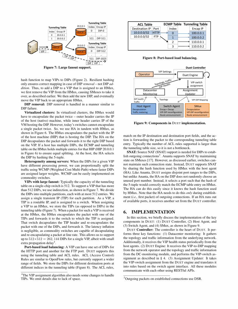
VIPs with large fanout: Typically the capacity of the tunnelingtable on a single-chip switch is 512. To support a VIP that has morethan 512 DIPs, we use indirection, as shown in Figure 7. We dividethe DIPs into multiple partitions, each with at most 512 entries. Weassign a single transient IP (TIP) for each partition. As a VIP, aTIP is a routable IP, and is assigned to a switch. When assigninga VIP to an HMux, we store the TIPs (as opposed to DIPs) in thetunneling table (Figure 7). When a packet for such a VIP is receivedat the HMux, the HMux encapsulates the packet with one of theTIPs and forwards it to the switch to which the TIP is assigned.That switch decapsulates the TIP header and re-encapsulates thepacket with one of the DIPs, and forwards it. The latency inflationis negligible, as commodity switches are capable of decapsulatingand re-encapsulating a packet at line rate. This allows us to supportup to 512∗512 = 262, 144 DIPs for a single VIP, albeit with smallextra propagation delay4.
Port-based load balancing: A VIP can have one set of DIPs forthe HTTP port and another for the FTP port. DUET supports thisusing the tunneling table and ACL rules. ACL (Access Control)Rules are similar to OpenFlow rules, but currently support a widerrange of fields. We store the DIPs for different destination ports atdifferent indices in the tunneling table (Figure 8). The ACL rules,
4The VIP assignment algorithm also needs some changes to handleTIPs. We omit details due to lack of space.
ACL Table Tunneling Table Index
0
1
2
3
ECMP Table Encap IP
100.0.0.1
100.0.0.2
110.0.0.1
110.0.0.2
Destination IP Port 10.0.0.0/32 HTTP 10.0.0.0/32 FTP
match on the IP destination and destination port fields, and the ac-tion is forwarding the packet to the corresponding tunneling tableentry. Typically the number of ACL rules supported is larger thanthe tunneling table size, so it is not a bottleneck.
SNAT: Source NAT (SNAT) support is needed for DIPs to estab-lish outgoing connections5. Ananta supports SNAT by maintainingstate on SMuxes [17]. However, as discussed earlier, switches can-not maintain such connection state. Instead, DUET supports SNATby sharing the hash function used by HMux with the host agent(HA). Like Ananta, DUET assigns disjoint port ranges to the DIPs,but unlike Ananta, the HA on the DIP does not randomly choose anunused port number. Instead, it selects a port such that the hash ofthe 5-tuple would correctly match the ECMP table entry on HMux.The HA can do this easily since it knows the hash function usedby HMux. Note that the HA needs to do this only during establish-ment (i.e., first packet) of outgoing connections. If an HA runs outof available ports, it receives another set from the DUET controller.
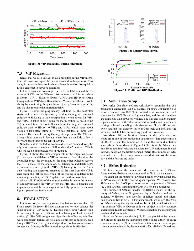
6. IMPLEMENTATIONIn this section, we briefly discuss the implementation of the key
components in DUET: (1) DUET Controller, (2) Host Agent, and(3) Switch Agent, and (4) SMux, as shown in Figure 9.
DUET Controller: The controller is the heart of DUET. It per-forms three key functions: (1) Datacenter monitoring: It gathersthe topology and traffic information from the underlying network.Additionally, it receives the VIP health status periodically from thehost agents. (2) DUET Engine: It receives the VIP-to-DIP mappingfrom the network operator and the topology and traffic informationfrom the DC-monitoring module, and performs the VIP-switch as-signment as described in § 4. (3) Assignment Updater: It takesthe VIP-switch assignment from the DUET engine and translates itinto rules based on the switch agent interface. All these modulescommunicate with each other using RESTful APIs.
5Outgoing packets on established connections use DSR.
Agg
ToR
Server + SMux
2 1 Core
Container-1
2
2
1
S M S …
1
S M S …
4
4
3
S S …
3
S M S …
Container-2
Figure 10: Our testbed. FatTree with two containers of two Aggand two ToR Switches each, connected by two Core switches.
0
10
20
30
0 100 200 300
Late
ncy (
msec)
Time (sec)
SMux (600k) SMux (1.2M) HMux (1.2M)
Figure 11: HMux has higher capacity.
Switch Agent: The switch agent runs on every switch. It usesvendor-specific APIs to program the ECMP and tunneling tables,and provides RESTful APIs which are used by the assignment up-dater to add/remove VIP-DIP mapping. On every VIP change, theswitch agent fires touting updates over BGP.
Host Agent and SMux: The host agent and SMux implementa-tion are the same as in Ananta. The host agent primarily performspacket decapsulation, SNAT and DIP health monitoring. Addition-ally, the host agents perform traffic metering and report the statis-tics to the DUET controller.
Same as in Ananta, we run a BGP speaker along side of eachSMux to advertise all the VIPs assigned to the SMux.
In total, the controller code consists of 4200 LOC written in C#,and the switch agent code has about 300 LOC in Python.
and 60 servers. Of the 60 servers, 34 act as DIPs and the others areused to generate traffic. Each of ToRs 1, 2 and 3 is also connectedto a server acting as SMux.
Our testbed experiments show: (1) HMuxes provide higher ca-pacity, (2) DUET achieves high availability during HMux failure asthe VIP traffic seamlessly falls back to SMuxes, and (3) VIP mi-gration is fast, and DUET maintains high availability during VIPmigration.
7.1 HMux CapacityIf the load balancer instances have low capacity, packet queues
will start building up, and traffic will experience high latency.This experiment illustrates that individual HMuxes instances (i.e.,a switch) have significantly higher capacity than individual SMuxinstances.
The experiment uses 11 VIPs, each with 2 DIPs. We send UDPtraffic to 10 of the VIPs, leaving the 11th VIP unloaded.
0
1
0 50 100 150 200
Time (msec)
VIP1
0
1
Late
ncy (
msec)
VIP2
0
1Tfail TrecoverVIP3
VIP on HMux VIP on SMux
Figure 12: VIP availability during failure.
The experiment has three steps. (1) All 11 VIPs are assigned tothe SMuxes, and we generate a total traffic of 600K packets persecond to the 10 VIPs (60K per VIP). Since each VIP is announcedfrom every SMux, the traffic is split evenly between all SMuxes,and each SMux is handling 200K packets per second. (2) At time100 sec, we increase the traffic to 1.2M packets per second, so eachSMux is handling 400K packets per second. (3) Finally, at time200 sec, we switch all VIPs to a single HMux hosted on ToR 1.
The metric of interest is the latency to the unloaded VIP, mea-sured using pings sent every 3ms. We measure the latency to theunloaded VIP so that the latency only reflects the delay suffered atthe SMux or HMux – the VIP or the DIP itself is not the bottleneck.The results shown in Figure 11.
We see that until time 100 sec, the latency is mostly below 1ms,with a few outliers. This is because each SMux is handling only200K packets per second, which is well within its capacity (300Kpackets per second – see §2), and thus there is no significant queuebuildup. At time 100, the latency jumps up – now each SMux ishandling 400K packets per second, which is well beyond its ability.Finally, at time 200 sec, when all VIPs are on a single HMux, thelatency goes down to 1ms again. This shows that a single HMuxinstance has higher capacity than at least 3 SMux instances.
In fact, since HMux processes all packets in the data plane of theswitch, it can handle packets at line rate, and no queue buildup willoccur till we exceed the link capacity (10Gbps in this experiment).
7.2 HMux Failure MitigationOne of the most important benefits of using the SMux as a back-
stop is automatic failure mitigation, as described in §5. In this ex-periment, we investigate the delay involved in failing over from anHMux to an SMux. This delay is important because during failover,traffic to the VIP gets disrupted.
We assign 7 VIPs across HMuxes and the remaining 3 to theSMuxes. We fail one switch at 100 msec. We measure the impactof HMux failure on VIP availability by monitoring the ping latencyto all 10 VIPs every 3ms.
Figure 12 shows the ping latency for three VIPs: (1) One on thefailed HMux (VIP3), (2) One on a healthy HMux (VIP2), and (3)One on an SMux (VIP1), respectively.
We make three observations: (1) The traffic to VIP3 falls overto SMux within 38 msec after HMux failure. The delay reflectsthe time it takes for other switches to detect the failure, and for therouting to converge. The VIP was not available during this period,i.e., there is no response to pings. (2) After 38 msec, pings to VIP3
are successful again. (3) The VIPs assigned to other HMuxes andSMuxes are not affected; their latency is unchanged during HMuxfailure. These observations demonstrate the effectiveness of usingSMux as a backstop in the DUET design.
0
1
0 300 600 900 1200 1500
Time (msec)
VIP1
0
1
Late
ncy (
msec)
VIP2
0
1T1 T2VIP3
T3
VIP on HMux VIP on SMux
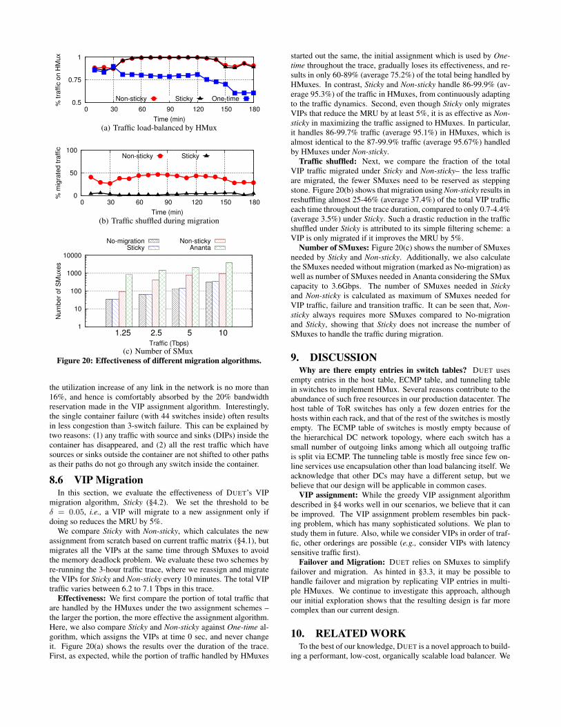
Figure 13: VIP availability during migration.
7.3 VIP MigrationRecall that we also use SMux as a backstop during VIP migra-
tion. We now investigate the delays involved in this process. Thisdelay is important because it places a lower bound on how quicklyDUET can react to network conditions.
In this experiment, we assign 7 VIPs to the HMuxes and the re-maining 3 VIPs to the SMuxes. We migrate a VIP from HMux-to-SMux (VIP1), SMux-to-HMux (VIP2), and HMux-to-HMuxthrough SMux (VIP3) at different times. We measure the VIP avail-ability by monitoring the ping latency (every 3ms) to these VIPs,and we also measure the migration delay.
Figure 13 shows the ping latency. At time T1, the controllerstarts the first wave of migration by sending the migrate command(migrate to SMuxes) to the corresponding switch agents for VIP1
and VIP3. It takes about 450ms for the migration to finish (timeT2), at which time, the controller sends another migrate command(migrate back to HMux) to VIP2 and VIP3, which takes about400ms to take effect (time T3). We see that that all three VIPsremain fully available during the migration process. The VIPs seea very slight increase in latency when they are on SMux, due tosoftware processing of packets on SMux.
Note that unlike the failure scenario discussed earlier, during themigration process, there is no “failure detection” involved. This iswhy we see no ping packet loss in Figure 13.
Figure 14 shows the three components of the migration delay:(1) latency to add/delete a VIP as measured from the time thecontroller sends the command to the time other switches receivethe BGP update for the operation, (2) latency to add/delete DIPsas measured similarly as the VIPs, (3) latency for the BGP up-date (routing convergence), measured as the time from the VIP ischanged in the FIB on one switch till the routing is updated in theremaining switches, i.e., BGP update time on those switches.
Almost all (80-90%) of the migration delay is due to the latencyof adding/removing the VIP to/from the FIB. This is because ourimplementation of the switch agent is not fully optimized – improv-ing it is part of our future work.
8. EVALUATIONIn this section, we use large-scale simulations to show that: (1)
DUET needs far fewer SMuxes than Ananta to load balance thesame amount of VIP traffic; (2) Despite using fewer SMuxes (andhence being cheaper), DUET incurs low latency on load balancedtraffic; (3) The VIP assignment algorithm is effective; (4) Net-work component failures do not cause significant congestion, eventhough DUET’s VIP assignment algorithm is oblivious to networkcomponent failures; (5) The migration algorithm is effective.
0
100
200
300
400
500
600
La
ten
cy (
mse
c)
Add-DIPsAdd-VIP
VIP-Announce
(a) Add 0
100
200
300
400
500
600
La
ten
cy (
mse
c)
Delete-DIPsDelete-VIP
VIP-Withdraw
(b) DeleteFigure 14: Latency breakdown.
0
0.2
0.4
0.6
0.8
1
0 0.2 0.4 0.6 0.8 1
CD
F
Fraction of Total VIPs
BytesPackets
DIPs
Figure 15: Traffic and DIP distribution.
8.1 Simulation SetupNetwork: Our simulated network closely resembles that of a
production datacenter, with a FatTree topology connecting 50kservers connected to 1600 ToRs located in 40 containers. Eachcontainer has 40 ToRs and 4 Agg switches, and the 40 containersare connected with 40 Core switches. The link and switch memorycapacity were set with values observed in production datacenters:routing table and tunneling table sizes set to 16k and 512, respec-tively, and the link capacity set to 10Gbps between ToR and Aggswitches, and 40 Gbps between Agg and Core switches.
Workload: We run the simulations using the traffic trace col-lected from one of our production datacenters. The trace consistsof 30K VIPs, and the number of DIPs and the traffic distributionacross the VIPs are shown in Figure 15. We divide the 3-hour traceinto 10-minute intervals, and calculate the VIP assignment in eachinterval, based on the traffic demand matrix (the number of bytessent and received between all sources and destinations), the topol-ogy and the forwarding tables.
8.2 SMux ReductionWe first compare the number of SMuxes needed in DUET and
Ananta to load-balance same amount of traffic in the datacenter.We calculate the number of SMuxes needed by Ananta such that
no SMux receives traffic exceeding its capacity. We consider twoSMux capacities: 3.6Gbps, as observed on the production SMuxes(§2), and 10Gbps, assuming the CPU will not be a bottleneck.
The number of SMuxes needed for DUET depends on the ca-pacity of SMux, the traffic generated by VIPs that could not beassigned to HMuxes, and specifics of failure model, and migra-tion probabilities (§3.3). In this experiment, we assign the VIPsto HMuxes using the algorithm described in §4, which tries to as-sign as many VIPs to HMuxes as it can, subject to switch memoryand link bandwidth constraints. We have specified the memory andbandwidth details earlier.
Based on failure scenarios in [13, 21], we provision the numberof SMuxes to handle the maximum traffic under either (1) entirecontainer failure, or (2) three random switch failures. For example,if an entire container fails, the total traffic T to all the VIPs assigned
1
10
100
1000
10000
1.25 2.5 5 10Nu
mbe
r of
SM
uxe
s
Traffic (Tbps)
Duet(10G)Duet
Ananta(10G)Ananta
Figure 16: Number of SMuxes used in Duet and Ananta.
102
103
104
5k 10k 15k
Late
ncy (
usec)
Number of SMuxes
AnantaDuet
Figure 17: Latency (microseconds) vs. number of SMuxes inAnanta and DUET.
to the switches inside need to fail over to SMuxes. Thus the numberof SMuxes needed is T
Csmuxwhere Csmux is SMux capacity.
We ignore migration – it is covered in §8.6.Figure 16 shows that DUET requires far fewer SMuxes compared
to Ananta at all traffic rates. Note the log scale on Y axis. For allthe traffic rates, DUET was able to assign 16k VIPs to the HMuxes(routing table limit). Overall, compared to Ananta, DUET requires12-24x times fewer SMuxes when the SMux capacity is 3.6 Gbpsand 8-12x times fewer SMuxes when the SMux capacity is 10Gbps,across different traffic loads.
We note that for all traffic scenarios, majority of the SMuxesneeded by DUET were needed to handle failure. The fraction ofSMuxes needed to handle the traffic to the VIPs that could not beassigned to the HMux is small. This shows that the VIP assignmentalgorithm does a good job of “packing” VIPs into HMuxes.
8.3 Latency vs. SMuxesAnother way to look at the trade-off described in §8.2 is to hold
the traffic volume constant, and see how many SMuxes Anantaneeds to provide the same latency as DUET. This is shown in fig-ure 17.
We hold the traffic at 10Tbps, and vary the number of SMuxesfor Ananta from 2000 to 15,000. The black line shows medianlatency for Ananta. The red dot represents DUET. DUET used 230SMuxes, and achieved median latency of 474 µsec.
We see that if Ananta were to use the same number of SMuxes asDUET (230), the median latency would be many times higher (over6 ms). On the other hand, Ananta needs 15,000 SMuxes to achievelatency comparable to DUET.
The absolute latency numbers may appear small – however, re-call that median DC RTTs are of the order of 381 µsec6, and inmany cases, to satisfy a single user request, an application likeSearch traverses load balancer multiple times. Any time lost in thenetwork is wasted time – which could have otherwise been used bythe application to improve user experience [8, 14, 19].
6Newer technologies such a RDMA lower this to 2-5 µsec!
1
10
100
1000
1.25 2.5 5 10
Num
ber
of S
Muxes
Traffic (Tbps)
DuetRandom
Figure 18: Number of SMuxes used by Duet and Random.
0
0.2
0.4
0.6
0.8
1
1.2
1.25 2.5 5 10
Max. L
ink U
tiliz
atio
n
Traffic (Tbps)
NormalSwitch-fail
Container-fail
Figure 19: Impact of failures on max. link utilization.
8.4 Duet vs. RandomTo understand the impact of assigning VIPs based on the max-
imum resource utilization, we compare the performance of DUETin terms of the number of SMuxes against a random strategy (Ran-dom) that selects the first feasible switch that does not violate thelink or switch memory capacity. This assignment algorithm can beviewed as a variant of FFD (First Fit Decreasing) as the VIPs areassigned in the sorted order of decreasing traffic volume.
Figure 18 shows the total number of SMuxes needed by DUETand Random (note the log scale). We see that Random results in120%–307% more SMuxes compared to DUET as the traffic loadvaries from 1.25 to 10 Tbps. This shows that by taking resourceutilization into account, DUET ensures that only a small fraction ofVIPs traffic is left to be handled by the SMuxes.
8.5 Impact of FailureMicrobenchmark results in §7.2 showed that DUET can handle
HMux failures well – the VIPs fall back to SMux, and the disrup-tion to the VIP traffic is minimal. In §8.2, we considered the num-ber of SMuxes DUET needs to cope with failures. We now considerthe bigger picture – what impact does failures of several switches,or even a container have on overall traffic?
We consider the same failure model as was used in §8.2 – a con-tainer or up to 3 switches can fail simultaneously. We evaluate fail-ure resilience of DUET by measuring the maximum link utilizationunder these two scenarios: failure of a randomly selected container,or 3 randomly selected switches.
A random switch failure affects link traffic load in two ways.It causes the traffic of the VIPs assigned to the failed switch tobe shifted to the backstop SMuxes, and other through traffic to beshifted to the alternative path. A container failure affects the trafficin more complicated ways: it not only causes all the switches insideto be disconnected, but also makes all the traffic with sources anddestinations (DIPs) inside to disappear.
Figure 19 shows the measured maximum link utilization duringthe two failure scenarios in the 10 experiments. We see that asexpected, link failures can result in transient congestion. However,
0.5
0.75
1
0 30 60 90 120 150 180
% tra
ffic
on H
Mux
Time (min)
Non-sticky Sticky One-time
(a) Traffic load-balanced by HMux
0
50
100
0 30 60 90 120 150 180
% m
igra
ted tra
ffic
Time (min)
Non-sticky Sticky
(b) Traffic shuffled during migration
1
10
100
1000
10000
1.25 2.5 5 10
Num
ber
of S
Muxes
Traffic (Tbps)
No-migrationSticky
Non-stickyAnanta
(c) Number of SMuxFigure 20: Effectiveness of different migration algorithms.
the utilization increase of any link in the network is no more than16%, and hence is comfortably absorbed by the 20% bandwidthreservation made in the VIP assignment algorithm. Interestingly,the single container failure (with 44 switches inside) often resultsin less congestion than 3-switch failure. This can be explained bytwo reasons: (1) any traffic with source and sinks (DIPs) inside thecontainer has disappeared, and (2) all the rest traffic which havesources or sinks outside the container are not shifted to other pathsas their paths do not go through any switch inside the container.
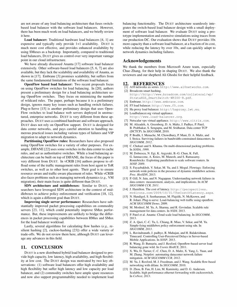
8.6 VIP MigrationIn this section, we evaluate the effectiveness of DUET’s VIP
migration algorithm, Sticky (§4.2). We set the threshold to beδ = 0.05, i.e., a VIP will migrate to a new assignment only ifdoing so reduces the MRU by 5%.
We compare Sticky with Non-sticky, which calculates the newassignment from scratch based on current traffic matrix (§4.1), butmigrates all the VIPs at the same time through SMuxes to avoidthe memory deadlock problem. We evaluate these two schemes byre-running the 3-hour traffic trace, where we reassign and migratethe VIPs for Sticky and Non-sticky every 10 minutes. The total VIPtraffic varies between 6.2 to 7.1 Tbps in this trace.
Effectiveness: We first compare the portion of total traffic thatare handled by the HMuxes under the two assignment schemes –the larger the portion, the more effective the assignment algorithm.Here, we also compare Sticky and Non-sticky against One-time al-gorithm, which assigns the VIPs at time 0 sec, and never changeit. Figure 20(a) shows the results over the duration of the trace.First, as expected, while the portion of traffic handled by HMuxes
started out the same, the initial assignment which is used by One-time throughout the trace, gradually loses its effectiveness, and re-sults in only 60-89% (average 75.2%) of the total being handled byHMuxes. In contrast, Sticky and Non-sticky handle 86-99.9% (av-erage 95.3%) of the traffic in HMuxes, from continuously adaptingto the traffic dynamics. Second, even though Sticky only migratesVIPs that reduce the MRU by at least 5%, it is as effective as Non-sticky in maximizing the traffic assigned to HMuxes. In particular,it handles 86-99.7% traffic (average 95.1%) in HMuxes, which isalmost identical to the 87-99.9% traffic (average 95.67%) handledby HMuxes under Non-sticky.
Traffic shuffled: Next, we compare the fraction of the totalVIP traffic migrated under Sticky and Non-sticky– the less trafficare migrated, the fewer SMuxes need to be reserved as steppingstone. Figure 20(b) shows that migration using Non-sticky results inreshuffling almost 25-46% (average 37.4%) of the total VIP trafficeach time throughout the trace duration, compared to only 0.7-4.4%(average 3.5%) under Sticky. Such a drastic reduction in the trafficshuffled under Sticky is attributed to its simple filtering scheme: aVIP is only migrated if it improves the MRU by 5%.
Number of SMuxes: Figure 20(c) shows the number of SMuxesneeded by Sticky and Non-sticky. Additionally, we also calculatethe SMuxes needed without migration (marked as No-migration) aswell as number of SMuxes needed in Ananta considering the SMuxcapacity to 3.6Gbps. The number of SMuxes needed in Stickyand Non-sticky is calculated as maximum of SMuxes needed forVIP traffic, failure and transition traffic. It can be seen that, Non-sticky always requires more SMuxes compared to No-migrationand Sticky, showing that Sticky does not increase the number ofSMuxes to handle the traffic during migration.
9. DISCUSSIONWhy are there empty entries in switch tables? DUET uses
empty entries in the host table, ECMP table, and tunneling tablein switches to implement HMux. Several reasons contribute to theabundance of such free resources in our production datacenter. Thehost table of ToR switches has only a few dozen entries for thehosts within each rack, and that of the rest of the switches is mostlyempty. The ECMP table of switches is mostly empty because ofthe hierarchical DC network topology, where each switch has asmall number of outgoing links among which all outgoing trafficis split via ECMP. The tunneling table is mostly free since few on-line services use encapsulation other than load balancing itself. Weacknowledge that other DCs may have a different setup, but webelieve that our design will be applicable in common cases.
VIP assignment: While the greedy VIP assignment algorithmdescribed in §4 works well in our scenarios, we believe that it canbe improved. The VIP assignment problem resembles bin pack-ing problem, which has many sophisticated solutions. We plan tostudy them in future. Also, while we consider VIPs in order of traf-fic, other orderings are possible (e.g., consider VIPs with latencysensitive traffic first).
Failover and Migration: DUET relies on SMuxes to simplifyfailover and migration. As hinted in §3.3, it may be possible tohandle failover and migration by replicating VIP entries in multi-ple HMuxes. We continue to investigate this approach, althoughour initial exploration shows that the resulting design is far morecomplex than our current design.
10. RELATED WORKTo the best of our knowledge, DUET is a novel approach to build-
ing a performant, low-cost, organically scalable load balancer. We
are not aware of any load balancing architecture that fuses switch-based load balancer with the software load balancers. However,there has been much work on load balancers, and we briefly reviewit here.
Load balancer: Traditional hardware load balancers [4, 1] areexpensive and typically only provide 1+1 availability. DUET ismuch more cost effective, and provides enhanced availability byusing SMuxes as a backstop. Importantly, compared to traditionalload balancers, DUET gives us control over very important vantagepoint in our cloud infrastructure.
We have already discussed Ananta [17] software load balancerextensively. Other software-based load balancers [5, 6, 7] are alsoavailable, but they lack the scalability and availability of Ananta, asshown in [17]. Embrane [3] promises scalability, but suffers fromthe same fundamental limitations of the software load balancer.
OpenFlow based load balancer: Two recent proposals focuson using OpenFlow switches for load balancing. In [20], authorspresent a preliminary design for a load balancing architecture us-ing OpenFlow switches. They focus on minimizing the numberof wildcard rules. The paper, perhaps because it is a preliminarydesign, ignores many key issues such as handling switch failures.Plug-n-Serve [15] is another preliminary design that uses Open-Flow switches to load balance web servers deployed in unstruc-tured, enterprise networks. DUET is very different from these ap-proaches. DUET uses a combined hardware and software approach.DUET does not rely on OpenFlow support. DUET is designed fordata center networks, and pays careful attention to handling nu-merous practical issues including various types of failures and VIPmigration to adapt to network dynamics.
Partitioning OpenFlow rules: Researchers have also proposedusing OpenFlow switches for a variety of other purposes. For ex-ample, DIFANE [22] uses some switches in the data center to cacherules, and act as authoritative switches. While a load balancing ar-chitecture can be built on top of DIFANE, the focus of the paper isvery different from DUET. In vCRIB [16] authors propose to of-fload some of the traffic management rules from host agent to ToRswitches, as well as to other host agents. Their goal is to ensureresource-aware and traffic-aware placement of rules. While vCRIBalso faces problems such as managing network dynamics (e.g., VMmigration), their main focus is quite different than DUET.
SDN architecture and middleboxes: Similar to DUET, re-searchers have leveraged SDN architecture in the context of mid-dleboxes to achieve policy enforcement and verification [18, 12],which is again a different goal than DUET.
Improving single server performance: Researchers have sub-stantially improved packet processing capabilities on commodityservers [23, 11], which could potentially improve SMux perfor-mance. But, these improvements are unlikely to bridge the differ-ences in packet processing capabilities between HMux and SMuxfor the load balancer workload.
Lastly, several algorithms for calculating flow hashes (e.g., re-silient hashing [2], cuckoo-hashing [23]) offer a wide variety oftrade-offs. We do not review them here, although DUET can lever-age any advances in this field.
11. CONCLUSIONDUET is a new distributed hybrid load balancer designed to pro-
vide high capacity, low latency, high availability, and high flexibil-ity at low cost. The DUET design was motivated by two key ob-servations: (1) software load balancers offer high availability andhigh flexibility but suffer high latency and low capacity per loadbalancer, and (2) commodity switches have ample spare resourcesand now also support programmability needed to implement load
balancing functionality. The DUET architecture seamlessly inte-grates the switch-based load balancer design with a small deploy-ment of software load balancer. We evaluate DUET using a pro-totype implementation and extensive simulations using traces fromour production DC. Our evaluation shows that DUET provides 10xmore capacity than a software load balancer, at a fraction of its cost,while reducing the latency by over 10x, and can quickly adapt tonetwork dynamics including failures.
AcknowledgementsWe thank the members from Microsoft Azure team, especiallyChao Zhang, for their help in shaping DUET. We also thank thereviewers and our shepherd Ali Ghodsi for their helpful feedback.
http://www.load-balancer.org.[7] Netscalar vpx virtual appliance. http://www.citrix.com.[8] M. Alizadeh, A. Greenberg, D. A. Maltz, J. Padhye, P. Patel,
B. Prabhakar, S. Sengupta, and M. Sridharan. Data center TCP(DCTCP). In SIGCOMM, 2010.
[9] P. Bodík, I. Menache, M. Chowdhury, P. Mani, D. A. Maltz, andI. Stoica. Surviving failures in bandwidth-constrained datacenters. InSIGCOMM, 2012.
[10] C. Chekuri and S. Khanna. On multi-dimensional packing problems.In SODA, 1999.
[11] M. Dobrescu, N. Egi, K. Argyraki, B.-G. Chun, K. Fall,G. Iannaccone, A. Knies, M. Manesh, and S. Ratnasamy.Routebricks: Exploiting parallelism to scale software routers. InSOSP, 2009.
[12] S. Fayazbakhsh, V. Sekar, M. Yu, and J. Mogul. Flowtags: Enforcingnetwork-wide policies in the presence of dynamic middlebox actions.Proc. HotSDN, 2013.
[13] P. Gill, N. Jain, and N. Nagappan. Understanding network failures indata centers: measurement, analysis, and implications. In ACMSIGCOMM CCR, 2011.
[14] J. Hamilton. The cost of latency. http://perspectives.mvdirona.com/2009/10/31/TheCostOfLatency.aspx.
[15] N. Handigol, S. Seetharaman, M. Flajslik, N. McKeown, andR. Johari. Plug-n-serve: Load-balancing web traffic using openflow.ACM SIGCOMM Demo, 2009.
[16] M. Moshref, M. Yu, A. Sharma, and R. Govindan. Scalable rulemanagement for data centers. In NSDI, 2013.
[17] P. Patel et al. Ananta: Cloud scale load balancing. In SIGCOMM,2013.
[18] Z. A. Qazi, C.-C. Tu, L. Chiang, R. Miao, V. Sekar, and M. Yu.Simple-fying middlebox policy enforcement using sdn. InSIGCOMM, 2013.
[19] L. Ravindranath, J. padhye, R. Mahajan, and H. Balakrishnan.Timecard: Controlling User-Perceieved Delays in Server-basedMobile Applications. In SOSP, 2013.
[20] R. Wang, D. Butnariu, and J. Rexford. Openflow-based server loadbalancing gone wild. In Usenix HotICE, 2011.
[21] X. Wu, D. Turner, C.-C. Chen, D. A. Maltz, X. Yang, L. Yuan, andM. Zhang. Netpilot: automating datacenter network failuremitigation. ACM SIGCOMM CCR, 2012.
[22] M. Yu, J. Rexford, M. J. Freedman, and J. Wang. Scalable flow-basednetworking with difane. In SIGCOMM, 2010.
[23] D. Zhou, B. Fan, H. Lim, M. Kaminsky, and D. G. Andersen.Scalable, high performance ethernet forwarding with cuckooswitch.In CoNext, 2013.