DULCOMETER ® D1Cb / D1Cc Assembly and operating instructions Part no. 986362 BA DM 197 12/13 EN Please carefully read these operating instructions before use! · Do not discard! The operator shall be liable for any damage caused by installation or operating errors! Technical changes reserved.
Transcript
DULCOMETER® D1Cb / D1Cc
Assembly and operating instructions
Part no. 986362 BA DM 197 12/13 EN
Please carefully read these operating instructions before use! · Do not discard!The operator shall be liable for any damage caused by installation or operating errors!
Technical changes reserved.
General non-discriminatory approach
In order to make it easier to read, thisdocument uses the male form in grammat‐ical structures but with an implied neutralsense. It is aimed equally at both men andwomen. We kindly ask female readers fortheir understanding in this simplification ofthe text.
Supplementary information
Read the following supplementary infor‐mation in its entirety!
The following are highlighted separately inthe document:
n Enumerated lists
Instructions
ð Results of the instructions
Information
This provides important informationrelating to the correct operation of thesystem or is intended to make yourwork easier.
Safety information
Safety information are provided withdetailed descriptions of the endangeringsituation, see Ä Chapter 1.1 ‘Explanationof the safety information’ on page 7
Supplemental instructions
2
Table of contents1 Introduction............................................................................................................. 7
1.1 Explanation of the safety information............................................................. 71.2 Users' qualifications........................................................................................ 91.3 General Safety Information.......................................................................... 101.4 Correct and proper use................................................................................ 121.5 ID Code........................................................................................................ 13
3 D1Cb mounting..................................................................................................... 213.1 Scope of supply............................................................................................ 223.2 Installation (Wall Mounted) .......................................................................... 233.3 Installation - Control Panel Mounted (Optional) .......................................... 243.4 Wall Mounted Installation of D1Cb (Electrical) ............................................ 263.4.1 Opening the device................................................................................... 273.4.2 Electrical Installation (Wall Mounted) ....................................................... 283.4.3 Electrical Installation (Control Panel Mounted) ........................................ 293.4.4 Installation of Coaxial Cable to Guard Terminal XE1 ............................... 303.4.5 Cable Cross-Sections and Cable End Sleeves......................................... 313.4.6 Protective RC Circuit (Optional) ............................................................... 323.4.7 Terminal Wiring Diagram .......................................................................... 333.5 Switching of inductive loads......................................................................... 37
4 D1Cc mounting..................................................................................................... 394.1 DULCOMETER® D1Cc scope of supply...................................................... 404.2 Mounting - control panel installation DULCOMETER® D1Cc....................... 404.3 Electrical Installation (Control Panel Mounted)............................................ 434.3.1 Installation of Coaxial Cable to Guard Terminal XE1................................ 444.3.2 Cable Cross-Sections and Cable End Sleeves......................................... 314.3.3 Terminal diagram ..................................................................................... 474.4 Switching of inductive loads......................................................................... 37
Table of contents
3
5 Commissioning..................................................................................................... 515.1 Initial commissioning ................................................................................... 515.1.1 Selection of the Operating Language........................................................ 515.1.2 Selection of the Measured Variable and Measuring Range...................... 535.2 Activation Code for Extended Functions...................................................... 545.2.1 Extended Functions Obtainable with the Activation Code......................... 54
7 Measured Variables and Operating Menus for Amperometric Sensors............... 687.1 Reduced / Complete Operating Menu ......................................................... 657.2 Description of All Amperometric Measured Variables ................................. 697.3 Reduced Operating Menu ........................................................................... 707.4 Complete Operating Menu / Description of All Measured Variables............ 727.5 Calibration of All Amperometric Measured Variables .................................. 737.6 Calibration of the Sensor for Amperometric Measured Variables................ 747.6.1 Preparation for Calibration of the Sensors for Amperometric Measured
Variables .................................................................................................. 747.6.2 Calibration of Zero Point and Slope.......................................................... 757.7 Correcting value........................................................................................... 78
8 Measured Variables and Operating Menus for Potentiometric Sensors............... 798.1 Reduced / Complete Operating Menu ......................................................... 658.2 Description of pH, Redox and Fluoride Measured Variables ...................... 808.3 Reduced pH / Redox / Fluoride Operating Menu ........................................ 818.4 Complete Operating Menu/Description of pH / ORP / Fluoride.................... 838.5 Calibration of pH, ORP and Fluoride Sensors.............................................. 848.5.1 Description of the Calibration of pH Sensors ........................................... 85
Table of contents
4
8.5.2 Calibration of pH Sensors. Description of the Setting Ranges ................. 888.5.3 Calibration of pH Sensors. Description of the Error Messages ................ 888.5.4 Testing the Redox Sensor ........................................................................ 898.5.5 Description of the Calibration of Fluoride Sensors.................................... 928.6 Temperature correction value for pH and fluoride sensors.......................... 96
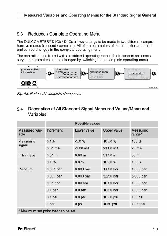
9 Measured Variables and Operating Menus for the Standard Signal General....... 989.1 Explanation of the Standard Signal General................................................ 989.2 Changing the Measured Variable .............................................................. 1009.3 Reduced / Complete Operating Menu ......................................................... 659.4 Description of All Standard Signal Measured Values/Measured
Variables ................................................................................................... 1019.5 Reduced Operating Menu ......................................................................... 1029.6 Complete Operating Menu / Description of All Measured Variables.......... 1049.7 Calibrating the Standard Signal ................................................................. 1049.7.1 Calibration of the Zero Point of the Standard Signal General................. 1069.7.2 Two-Point Calibration of the Standard Signal General............................ 107
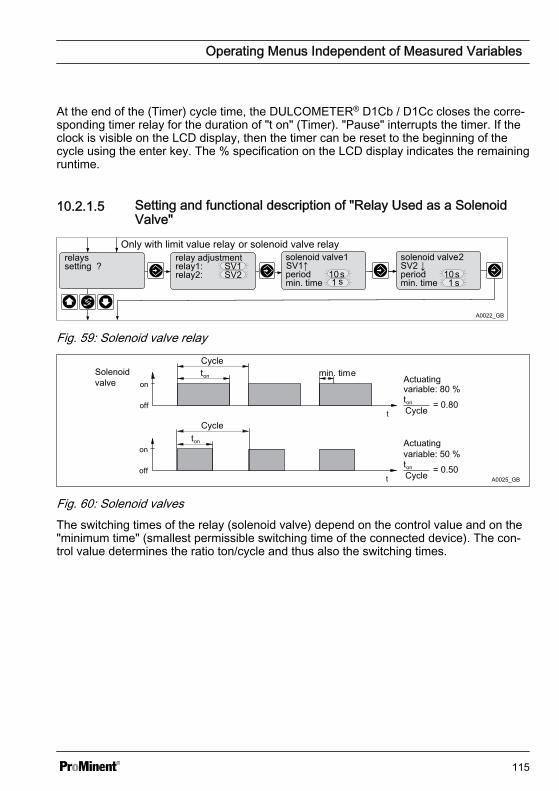
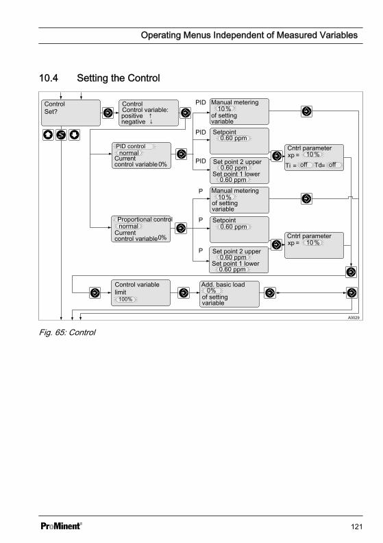
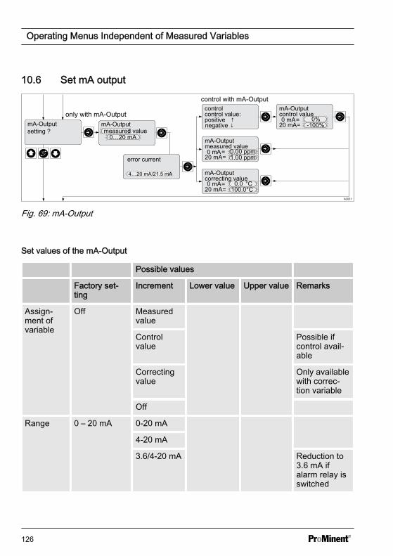
10 Operating Menus Independent of Measured Variables...................................... 10910.1 Pumps ..................................................................................................... 11010.2 Setting the Relays.................................................................................... 11210.2.1 Setting and Functional Description of the Relays.................................. 11310.3 Setting the Limits...................................................................................... 11810.4 Setting the Control.................................................................................... 12110.5 Setting metering control........................................................................... 12310.6 Set mA output........................................................................................... 12610.7 Device configuration................................................................................. 12810.7.1 Setting the Measured Variable/Measuring Range................................. 12810.7.2 Setting the [measured value]................................................................. 12910.7.3 Sub-Functions of the "General Settings" Menu..................................... 130
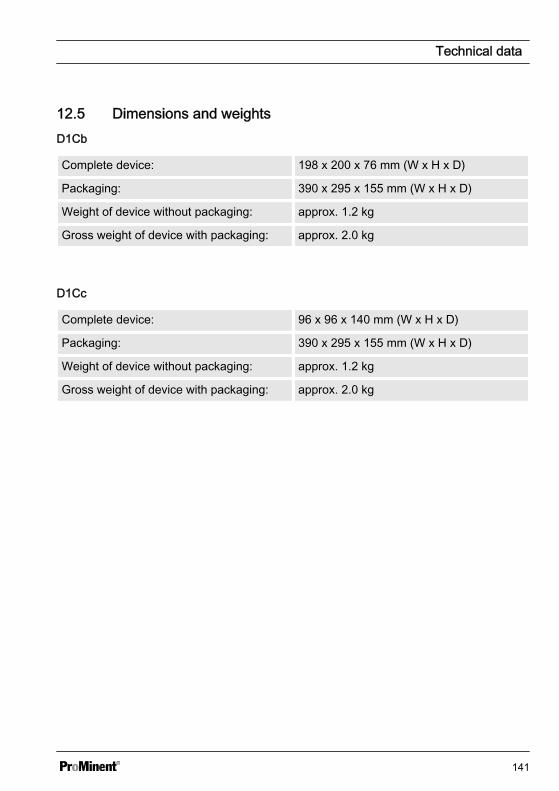
12.4 Chemical Resistance................................................................................ 14012.5 Dimensions and weights.......................................................................... 141
13 Electrical Data .................................................................................................... 142
14 Spare parts and accessories DULCOMETER® D1Cb / D1Cc............................ 146
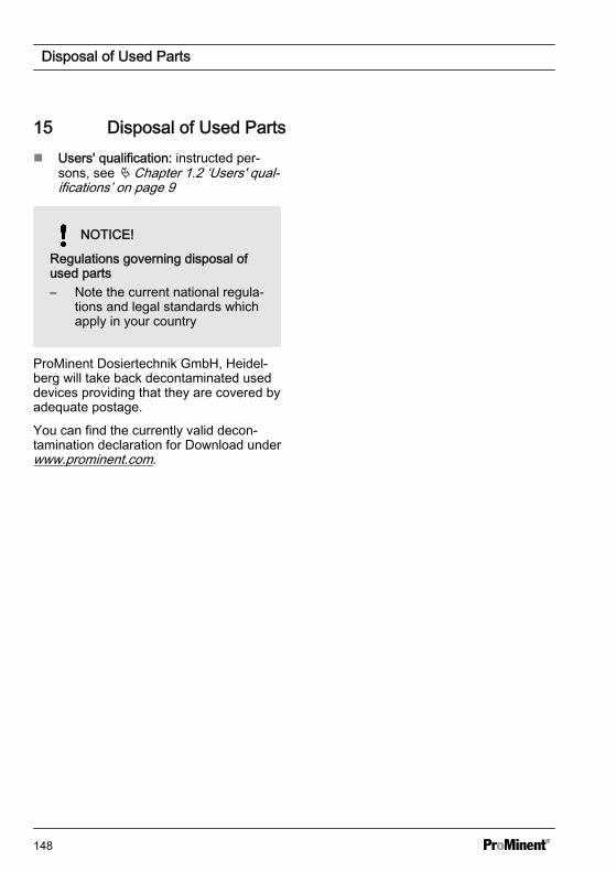
15 Disposal of Used Parts....................................................................................... 148
16 Standards complied with and Declaration of Conformity.................................... 149
1 IntroductionThese operating instructions provide infor‐mation on the technical data and functionsof the DULCOMETER® controllers of theproduct range D1Cb / D1Cc.
These operating instructions are valid forthe following controller software version:D1Cb ⋝ 01.04.01.00 // D1Cc ⋝01.02.01.00. Controllers with older soft‐ware versions must be updated to thelatest software version.
The controllers DULCOMETER®
D1Cb and DULCOMETER® D1Ccdiffer from each other only in theirtype of housing and mounting loca‐tion, not in their functionality.
1.1 Explanation of the safetyinformation
Introduction
These operating instructions provide infor‐mation on the technical data and functionsof the product. These operating instruc‐tions provide detailed safety informationand are provided as clear step-by-stepinstructions.
The safety information and notes are cate‐gorised according to the followingscheme. A number of different symbolsare used to denote different situations.The symbols shown here serve only asexamples.
DANGER!
Nature and source of the dangerConsequence: Fatal or very seriousinjuries.
Measure to be taken to avoid thisdanger
Danger!
– Denotes an immediate threat‐ening danger. If this is disre‐garded, it will result in fatal orvery serious injuries.
WARNING!
Nature and source of the dangerPossible consequence: Fatal or veryserious injuries.
Measure to be taken to avoid thisdanger
Warning!
– Denotes a possibly hazardous sit‐uation. If this is disregarded, itcould result in fatal or veryserious injuries.
Introduction
7
CAUTION!
Nature and source of the dangerPossible consequence: Slight orminor injuries, material damage.
Measure to be taken to avoid thisdanger
Caution!
– Denotes a possibly hazardous sit‐uation. If this is disregarded, itcould result in slight or minor inju‐ries. May also be used as awarning about material damage.
NOTICE!
Nature and source of the dangerDamage to the product or its sur‐roundings
Measure to be taken to avoid thisdanger
Note!
– Denotes a possibly damaging sit‐uation. If this is disregarded, theproduct or an object in its vicinitycould be damaged.
Type of informationHints on use and additional informa‐tionSource of the information, additionalmeasuresInformation!– Denotes hints on use and other
useful information. It does notindicate a hazardous or dam‐aging situation.
Introduction
8
1.2 Users' qualifications
WARNING!
Danger of injury with inadequately qualified personnel!The operator of the plant / device is responsible for ensuring that the qualificationsare fulfilled.
If inadequately qualified personnel work on the unit or loiter in the hazard zone of theunit, this could result in dangers that could cause serious injuries and materialdamage.
– All work on the unit should therefore only be conducted by qualified personnel.– Unqualified personnel should be kept away from the hazard zone
Training Definition
Instructed personnel An instructed person is deemed to be a person who has beeninstructed and, if required, trained in the tasks assigned to him/her and possible dangers that could result from improperbehaviour, as well as having been instructed in the requiredprotective equipment and protective measures.
Trained user A trained user is a person who fulfils the requirements made ofan instructed person and who has also received additionaltraining specific to the system from ProMinent or anotherauthorised distribution partner.
Trained qualified per‐sonnel
A qualified employee is deemed to be a person who is able toassess the tasks assigned to him and recognize possible haz‐ards based on his/her training, knowledge and experience, aswell as knowledge of pertinent regulations. The assessment ofa person's technical training can also be based on severalyears of work in the relevant field.
Introduction
9
Training Definition
Electrician Electricians are deemed to be people, who are able to com‐plete work on electrical systems and recognize and avoid pos‐sible hazards independently based on his/her technical trainingand experience, as well as knowledge of pertinent standardsand regulations.
Electricians should be specifically trained for the working envi‐ronment in which the are employed and know the relevantstandards and regulations.
Electricians must comply with the provisions of the applicablestatutory directives on accident prevention.
Customer Servicedepartment
Customer Service department refers to service technicians,who have received proven training and have been authorisedby ProMinent to work on the system.
Note for the system operatorThe pertinent accident prevention regulations, as well as all other generally acknowl‐edged safety regulations, must be adhered to!
1.3 General Safety Information
WARNING!
Live parts!Possible consequence: Fatal or veryserious injuries
– Measure: Disconnect the mainspower supply prior to opening thehousing
– De-energise damaged, defectiveor manipulated units by discon‐necting the mains plug
WARNING!
Unauthorised access!Possible consequence: Fatal or veryserious injuries
– Measure: Ensure that there canbe no unauthorised access to theunit
Introduction
10
WARNING!
Operating errors!Possible consequence: Fatal or veryserious injuries
– The unit should only be operatedby adequately qualified and tech‐nically expert personnel
– Please also observe the oper‐ating instructions for controllersand fittings and any other compo‐nent groups, such as sensors,measuring water pumps ...
– The operator is responsible forensuring that personnel are quali‐fied
CAUTION!
Electronic malfunctionsPossible consequence: Materialdamage to destruction of the unit
– The mains connection cable anddata cable should not be laidtogether with cables that areprone to interference
– Measure: Take appropriate inter‐ference suppression measures
NOTICE!
Correct and proper useDamage to the product or its sur‐roundings
– The unit is not intended tomeasure or regulate gaseous orsolid media
– The unit may only be used inaccordance with the technicaldetails and specifications pro‐vided in these operating instruc‐tions and in the operating instruc‐tions for the individualcomponents
NOTICE!
Correct sensor operation / Run-intimeDamage to the product or its sur‐roundings
– Correct measuring and dosing isonly possible if the sensor isworking perfectly
– It is imperative that the run-intimes of the sensors are adheredto
– The run-in times should beallowed for when planning initialoperation
– It may take a whole working dayto run-in the sensor
– Please read the operating instruc‐tions for the sensor
Introduction
11
NOTICE!
Correct sensor operationDamage to the product or its sur‐roundings
– Correct measuring and dosing isonly possible if the sensor isworking perfectly
– Check and calibrate the sensorregularly
NOTICE!
Compensation of control deviationsDamage to the product or its sur‐roundings
– This controller cannot be used incontrol circuits which requirerapid compensation (< 30 s)
1.4 Correct and proper use
NOTICE!
Compensation for control deviationsDamage to the product or its sur‐roundings
– The controller can be used in pro‐cesses, which require compensa‐tion of > 30 seconds
NOTICE!
Correct and proper useThe unit is intended to measure andregulate liquid media. The marking ofthe measured variables is located onthe controller and is absolutelybinding.
The unit may only be used in accord‐ance with the technical details andspecifications provided in this oper‐ating manual and in the operatingmanuals for the individual compo‐nents (such as, for example, sensors,fittings, calibration devices, meteringpumps etc.).
Any other uses or modifications areprohibited.
Introduction
12
1.5 ID CodeDevice identification / Identcode
DULCOMETER® controller series D1Cb / D1Cc
D1Cb / D1Cc
Type of mounting
W Wall mounted D1Cb (IP 65)
D Control panel installation D1Cc (IP54)
Version
00 with LCD and keypad / with ProMinent logo
Operating voltage
6 90...253 V, 50/60 Hz (wide voltage power unit)
Certification
01
CE mark
Hardware extension I
0 none
Hardware extension II
0 none
1 Protective RC circuit for power relay
External connection
0 none
Software default setting
U Default setting
V Software preset
Default measured variable
0 Universal I Chlorite
A Peracetic acid P pH
Introduction
13
DULCOMETER® controller series D1Cb / D1Cc
B Bromine R ORP
C Chlorine S 0/4...20 mA standardsignal general
D Chlorinedioxide
X Dissolved oxygen
F Fluoride Z Ozone
H Hydrogen per‐oxide
L Conductivity
Connection of the measured variable
1 mA input (standard signal 0/4-20 mA, allmeasured variables)
5 mV input (pH/ORP)
Correction variable
0 none
2 Temperature Pt 100/PT1000 (forpH, conductivity, fluoride, ClO2 CDPsensor)
4 Manual temperature input (for pH,conductivity, fluoride, ClO2 CDPsensor)
The DULCOMETER® D1Cb / D1Cc 4-wire measuring transducer/controller is a devicedesigned to measure/control a measured variable.
In the mA measuring version, the measured variable can be changed without restrictionsin the device menu. In the mV measurement version, the menu of theDULCOMETER® D1Cb / D1Cc only permits choice between pH and ORP.
Depending on the measured variable, sensors for pH or redox potential (ORP) oramperometric sensors can only be connected to the measured variables in line withÄ ‘Allocation of the measurement inputs of the DULCOMETER® D1Cb / D1Cc’ Tableon page 16. The temperature measurement serves as a correction variable and can bemeasured using a Pt 100/1000. This means that automatic temperature compensation ispossible with pH-value, conductivity and fluoride measured variables. Temperature com‐pensation is performed in the sensor (with the exception of the chlorine dioxide sensortype CDP) with amperometric measured variables (chlorine etc.). Operation of theDULCOMETER® D1Cb / D1Cc takes place via the menu keys. and the data is displayedby means of an illuminated LCD display. The LCD display ensures that the measuredvalue, correction variable, control value and error messages can be clearly read.
Allocation of the measurement inputs of the DULCOMETER® D1Cb / D1Cc
Connection of the measured vari‐able to:
Character Measured variable mV input mA input
0 no default setting
of the measured variable
(pH and redox can be selected)
X
A PES (peracetic acid) X
B Bromine X
C Chlorine X
D Chlorine dioxide X
F Fluoride X
*with measured value transducer
Functional description
16
Connection of the measured vari‐able to:
Character Measured variable mV input mA input
H H2O2 (hydrogen peroxide) X
I Chlorite X
P pH X X*
R ORP X X*
S 0/4...20 mA standard signal general X
X O2 X
Z O3 X
L Conductivity X
*with measured value transducer
Description of the terminal connections for mA and mV: see Fig. 11 and Fig. 12
Description of the operating menu of the measured variables via mV connection:seeÄ Chapter 8 ‘Measured Variables and Operating Menus for Potentiometric Sensors’on page 79Description of the operating menu of the measured variables via mA connection: seeÄ Chapter 7 ‘Measured Variables and Operating Menus for Amperometric Sensors’on page 68Description of the operating menu of the measured variables via mA standard signal: seeÄ Chapter 9 ‘Measured Variables and Operating Menus for the Standard Signal General’on page 982.1 Wall mounting/control panel
installationDULCOMETER® D1Cb
The DULCOMETER® D1Cb W is suitableboth for wall-mounting, as well as forinstallation in a control panel (with addi‐tional control panel mounting kit).
The plastic housing comprises a housingupper section and lower section. The LCDdisplay and membrane keypad areaccommodated in the upper section of thehousing.
The lower section of the housing accom‐modates the processor and power unitsand any optional assemblies. A ribboncable connects to the LCD display and themembrane keypad.
Functional description
17
The electrical connection is made throughoriginally sealed, push-out cable cut-outson the underside of the lower section ofthe housing.
A wall bracket for wall mounting is locatedon the rear of the lower section of thehousing.
DULCOMETER® D1Cc
The DULCOMETER® D1Cc is suitable forcontrol panel installation. In this respect iffulfils the same functions as the D1Cb.However, the D1Cc also has an option forupgrading with a protective RC circuit.When correctly installed, the D1Cc has anIP54 protection rating.
2.2 Electrical constructionThe device does not have a mains switch.It is therefore immediately ready for ope‐ration once connected to the powersupply.
The device processes an input signalwhilst taking into consideration operatorinputs. The result is displayed and madeavailable to other devices via a standardsignal. When equipped with actuators, thedevice can also provide control functions.It is designed to activate metering pumps,solenoid valves, as well as an mAstandard signal output. The activation var‐iable is recalculated every second.
Functional description
18
2.2.1 Block circuit diagram
NOTICE!
Connection of mV or mA sensorsThe DULCOMETER® D1Cb / D1Cc is suitable for the connection of mV or mA sen‐sors. It is not possible to connect mV and mA sensors simultaneously.
extern
er Sp
eiche
r /
EERO
M/Fla
sh
mV Ei
ngan
g /
mA Ei
ngan
g /
Konta
kteing
ang
Netzte
ilTe
mpera
turein
gang
/
Relais
ausga
ng 3
/
Relais
ausg
ang 2
/
Relais
ausga
ng 1
/
Konta
ktausg
ang 1
/
Konta
ktaus
gang
2 /
Strom
ausga
ng /
Fig. 1: Block circuit diagram
Functional description
19
2.2.2 Galvanic Isolation
WARNING!
Protective low voltage/Mains voltagePossible consequence: Fatal or very serious injuries
If relay 1 or 2 is operated with protective low voltage, no mains voltage may be con‐nected to the other relay.
Netzeingang /
Netzanschluss
pH Eingang /
mA Eingang /
Kontakteingang /
Temperatureingang /
Kontaktausgang 2 /
Kontaktausgang 1 /
mA Ausgang /
Alarmausgang /
Relaisausgang 1-2 * /
Fig. 2: Galvanic Isolation* If relay 1 or 2 is operated with protective low voltage, no mains voltage many be con‐
nected to the other relay.** No galvanic isolation between mA and mV input and temperature input.
Proceed as described under "ElectricalInstallation (Wall Mounted)". Refer toÄ Chapter 3.4.2 ‘ Electrical Installation(Wall Mounted) ’ on page 28Only the rear row of threaded holes(M20x1.5) should be used when thedevice is mounted in a control panel. Thefront row (M12x1.5) lies outside of thecontrol panel.
Connect up as per the electrical terminalwiring diagram. Refer to Ä Chapter 3.4.7‘Terminal Wiring Diagram ’ on page 33
D1Cb mounting
29
3.4.4 Installation of Coaxial Cable to Guard Terminal XE1
CAUTION!
Maximum length of the coaxial cable 10 mIncorrect reading due to too long a coaxial cable
Possible consequence: Slight or minor injuries, material damage
The maximum length of the coaxial cable may not exceed 10 m when using redox orpH sensors. The measured signal can otherwise be falsified by the effects of interfer‐ence.
If the gap between the pH/redox measuring point and the DULCOMETER ® D1Cb ismore than 10 metres, then the use of an interposed DULCOTEST ® transducer 4-20mA pH V1, rH V1 is recommended. The connection is then made via terminal XE4 ofthe DULCOMETER ® D1Cb.
The XE4 (mA input) terminal is a chargeable additional function!
When installing the coaxial cable for the guard terminal XE 1, the allowances shown onthe diagram for stripping insulation from the coaxial cable should be adhered to. Fig. 9
The guard terminal should be tightened until "hand-tight".
D1Cb mounting
30
optional
RC-Schutzbeschaltung
Sicherung
Programmierschnittstelle
Schirmklemme
Klemmenanordnung Ausführung Wandgerät
Konfektionierung Koaxialkabel zum Anschluss an D1Cb oder vorkonfektioniert in den Varianten
Detail Anschluss Koaxialkabel D1Cb
Fig. 9: Preparation of coaxial cable
3.4.5 Cable Cross-Sections and Cable End Sleeves
Minimum cross-sec‐tion
Maximum cross-section
Stripped insulationlength
Without cable endsleeve
0.25 mm2 1.5 mm2
Cable end sleevewithout insulation
0.20 mm2 1.0 mm2 8 - 9 mm
Cable end sleevewith insulation
0.20 mm2 1.0 mm2 10 - 11 mm
D1Cb mounting
31
3.4.6 Protective RC Circuit(Optional)
A protective RC circuit is recommendedfor operation with consumers, whichpresent an inductive load (e.g. motormetering pumps or solenoid meteringpumps). In these applications a protectiveRC circuit prevents wear and tear of therelay contacts. Refer to Ä ‘Spare partsand accessories DULCOMETER® D1Cb’ on page 146
D1Cb mounting
32
3.4.7 Terminal Wiring Diagram
Klem
mena
nord
nung
Ausfü
hrun
g: W
andm
ontag
e
Prog
ramm
iersc
hnitts
telle
Schir
mklem
me
Sich
erun
g 5x2
0
Fig. 10: Terminal layout
D1Cb mounting
33
Ne
tzN
etz
Magnetventil 2(senken)
Magnetventil 1(heben)
Ne
tzN
etz
Relais 3 / Alarm
Grenzwertrelais 1
Grenzwertrelais 2
Exte
rn
Be
leg
un
gsva
rian
ten
Va
rian
te 1
Ma
gn
etve
ntil
Gre
nzw
ertre
lais, T
ime
r, Ste
llglie
d(ohne R
C-Schutzbeschaltung)
Va
rian
te 2
Va
rian
te 2
Va
rian
te 1
Fig. 11: Terminal diagram with assignment options 1
D1Cb mounting
34
Netz
Normsignal-Eingang
Temperatur
Digital Eingang "Pause" oder Störgröße
Offen/geschl.
Potenzialfreier Kontakt nötig!
Drahtbrücke
-ProMinent Umformer
Normsignal-Eingang
Stromquelle
Extern Pumpe 2,senken (potenzialfrei)
Extern Pumpe 1,heben (potenzialfrei)
Normsignal-Ausgang1
1
Be
leg
un
gsva
riante
n
Temperatur
Potenzialausgleich
Be
leg
un
gsva
rian
ten
Fig. 12: Terminal diagram with assignment options 2
D1Cb mounting
35
Exte
rn
Ne
tz
Pumpe 2 (senken)
Pumpe 1 (heben)
RC-Schutzbeschaltung(optional)
Fig. 13: Protective RC circuit terminal diagram
D1Cb mounting
36
3.5 Switching of inductive loads
If you connect an inductive load, i.e. aconsumer which uses a coil (e.g. analpha motorised pump), then youmust protect your controller with aprotective circuit. If in doubt, consultan electrical technician for advice.
The RC member protective circuit is asimple, but nevertheless very effective,circuit. This circuit is also referred to as asnubber or Boucherot member. It is pri‐marily used to protect switching contacts.
When switching off, the connection inseries of a resistor and capacitor meansthat the current can fade out in a dampedoscillation.
Also when switching on, the resistor actsas a current limiter for the capacitorcharging process. The RC member pro‐tective circuit is highly suited to ACvoltage supplies.
The magnitude of the resistance R ofthe RC member is determined accordingto the following equation:
R=U/IL(U= Voltage divided by the load // IL =load current)
The magnitude of the capacitor is deter‐mined using the following equation:
Units: R = Ohm; U = Volt; IL = Ampere;C = µF
C=k * ILk=0,1...2 (dependent on the application).
Only use capacitors of class X2.
Units: R = Ohm; U = Volt; IL = Ampere;C = µF
If consumers are connected whichhave a high starting current (e.g. plug-in, switched mains power supplies),then a means of limiting the startingcurrent must be provided.
The switching-off process can be investi‐gated and documented using an oscillo‐scope. The voltage peak at the switchcontact depends on the selected RC com‐bination.
A0842
Fig. 14: Switching-off process shown onthe oscillogram.
D1Cb mounting
37
WARNING!
Mains voltagePossible consequence: Fatal or veryserious injuries
If mains voltage is connected to oneof the terminals XR1-XR3 or XP, thenno protective low voltage may be con‐nected to any other of these terminals(SELV).
A0835
Fig. 15: RC protective circuit for the relaycontactsTypical AC current application with aninductive load:
n 1) Load (e.g. alpha motorised pump)n 2) RC-protective circuit
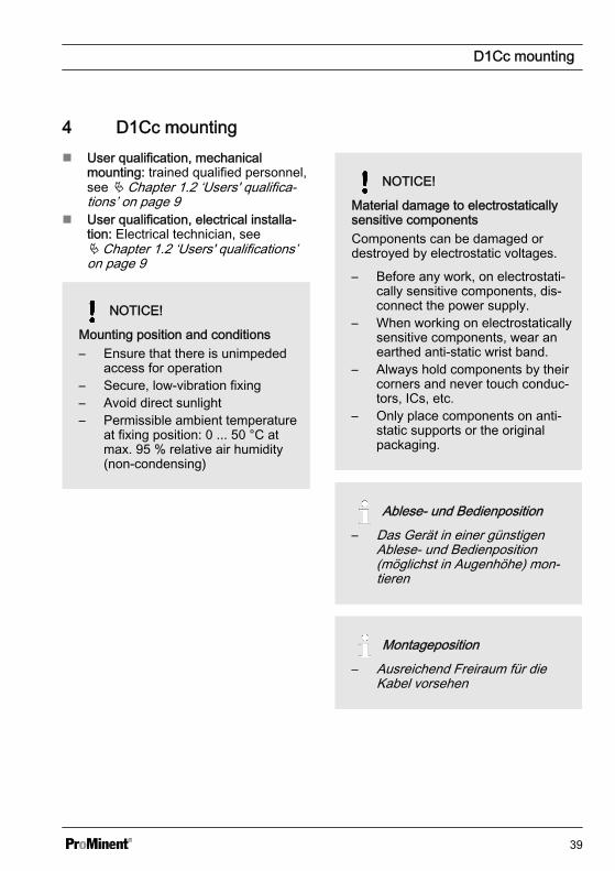
n User qualification, electrical installa‐tion: Electrical technician, seeÄ Chapter 1.2 ‘Users' qualifications’on page 9
NOTICE!
Mounting position and conditions– Ensure that there is unimpeded
access for operation– Secure, low-vibration fixing– Avoid direct sunlight– Permissible ambient temperature
at fixing position: 0 ... 50 °C atmax. 95 % relative air humidity(non-condensing)
NOTICE!
Material damage to electrostaticallysensitive componentsComponents can be damaged ordestroyed by electrostatic voltages.
– Before any work, on electrostati‐cally sensitive components, dis‐connect the power supply.
– When working on electrostaticallysensitive components, wear anearthed anti-static wrist band.
– Always hold components by theircorners and never touch conduc‐tors, ICs, etc.
– Only place components on anti-static supports or the originalpackaging.
Ablese- und Bedienposition– Das Gerät in einer günstigen
Ablese- und Bedienposition(möglichst in Augenhöhe) mon‐tieren
Montageposition– Ausreichend Freiraum für die
Kabel vorsehen
D1Cc mounting
39
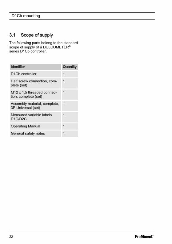
4.1 DULCOMETER® D1Cc scope of supplyThe following parts belong to the standard scope of supply of a DULCOMETER® seriesD1Cc controller.
Identifier Quantity
D1Cc controller 1
Retaining bracket 4
Measured variable labels D1C/D2C 1
Operating Manual 1
General safety notes 1
4.2 Mounting - control panel installation DULCOMETER® D1Cc
CAUTION!
Dimensional variationsPossible consequence: material damage
– Photocopying the punched template can result in dimensional deviations– Use the dimensions according to Fig. 16 and mark on the control panel
CAUTION!
Material thickness of control panelPossible consequence: material damage
– The material thickness of the control panel must be at least 2 mm to ensuresecure fixing
The device is designed for installation in a control panel. The housing corresponds to DIN43700. The control panel opening for installation of the device is specified in DIN 43700.We recommend a smaller opening. Fixing of the device is then better (less sidewaysplay) and the seal is uniformly compressed.
D1Cc mounting
40
92 +0,692
+0,6
90 +0,5
90 +0
,5
I. II.A0696
Fig. 16: Mounting - control panel installation DULCOMETER® D1CcI. DIN 43700 instructionII. ProMinent recommendation
D1Cc mounting
41
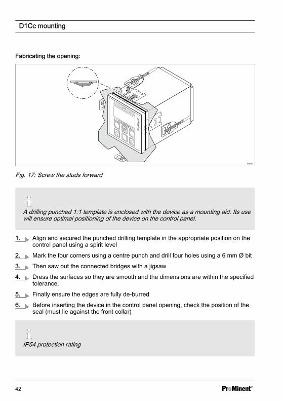
Fabricating the opening:
®®
STOPSTART
DULCOMETER®
D1C
A0697
Fig. 17: Screw the studs forward
A drilling punched 1:1 template is enclosed with the device as a mounting aid. Its usewill ensure optimal positioning of the device on the control panel.
1. Align and secured the punched drilling template in the appropriate position on thecontrol panel using a spirit level
2. Mark the four corners using a centre punch and drill four holes using a 6 mm Ø bit
3. Then saw out the connected bridges with a jigsaw
4. Dress the surfaces so they are smooth and the dimensions are within the specifiedtolerance.
5. Finally ensure the edges are fully de-burred
6. Before inserting the device in the control panel opening, check the position of theseal (must lie against the front collar)
IP54 protection rating
D1Cc mounting
42
7. Insert the device from the outside in the opening, attach the retaining bracket andpush backwards up to the stop
ð All four holes retaining brackets must be attached, as otherwise protectionrating IP54 cannot be adhered to.
8. Using a suitable screw driver, screw the studs forwards, see Fig. 17, until the sealis completely and uniformly compressed
9. Check the correct seating of the seal, as necessary loosen the studs and correctthe position
Connect up as per the electrical terminalwiring diagram. Refer to Ä Chapter 4.3.3‘Terminal diagram ’ on page 47
D1Cc mounting
43
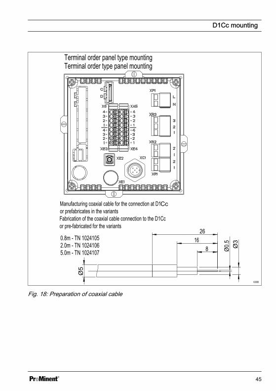
4.3.1 Installation of Coaxial Cable to Guard Terminal XE1
CAUTION!
Maximum length of the coaxial cable 10 mIncorrect measured value due to too long a coaxial cable
Possible consequence: Slight or minor injuries. Material damage.
The maximum length of the coaxial cable may not exceed 10 m when using redox orpH sensors. The measurement signal can otherwise be falsified by the effects ofinterference.
If the distance between the pH/ORP measuring point and the DULCOMETER® D1Ccis more than 10 m, the use of a DULCOTEST® measuring transducer 4-20 mA pHV1, rH V1 is recommended. Connection is then via terminal XE4 of theDULCOMETER® D1Cc
The XE4 (mA input) terminal is an auxiliary function that incurs an extra charge.
When installing the coaxial cable for the guard terminal XE 1, the allowances shown inthe diagram Fig. 18 for stripping insulation from the coaxial cable must be adhered to.The guard terminal should be tightened until "hand-tight".
D1Cc mounting
44
Terminal order panel type mounting
Fabrication of the coaxial cable connection to the D1Cc or pre-fabricated for the variants
A0698
Fig. 18: Preparation of coaxial cable
D1Cc mounting
45
4.3.2 Cable Cross-Sections and Cable End Sleeves
Minimum cross-sec‐tion
Maximum cross-section
Stripped insulationlength
Without cable endsleeve
0.25 mm2 1.5 mm2
Cable end sleevewithout insulation
0.20 mm2 1.0 mm2 8 - 9 mm
Cable end sleevewith insulation
0.20 mm2 1.0 mm2 10 - 11 mm
D1Cc mounting
46
4.3.3 Terminal diagram
Ne
tzN
etz
Magnetventil 2(senken)
Magnetventil 1(heben)
Ne
tzN
etz
Relais 3 / Alarm
Grenzwertrelais 1
Grenzwertrelais 2
Exte
rn
Be
leg
un
gsva
rian
ten
Va
rian
te 1
Ma
gn
etve
ntil
Gre
nzw
ertre
lais, T
imer, S
tellg
lied
(ohne RC
-Schutzbeschaltung)V
aria
nte
2
Va
rian
te 2
Va
rian
te 1
Fig. 19: Terminal diagram with assignment options 1
D1Cc mounting
47
Netz
Normsignal-Eingang
Temperatur
Digital Eingang "Pause" oder Störgröße
Offen/geschl.
Potenzialfreier Kontakt nötig!
Drahtbrücke
-ProMinent Umformer
Normsignal-Eingang
Stromquelle
Extern Pumpe 2,senken (potenzialfrei)
Extern Pumpe 1,heben (potenzialfrei)
Normsignal-Ausgang1
1
Be
leg
un
gsva
riante
n
Temperatur
Potenzialausgleich
Be
leg
un
gsva
rian
ten
Fig. 20: Terminal diagram with assignment options 2
D1Cc mounting
48
4.4 Switching of inductive loads
If you connect an inductive load, i.e. aconsumer which uses a coil (e.g. analpha motorised pump), then youmust protect your controller with aprotective circuit. If in doubt, consultan electrical technician for advice.
The RC member protective circuit is asimple, but nevertheless very effective,circuit. This circuit is also referred to as asnubber or Boucherot member. It is pri‐marily used to protect switching contacts.
When switching off, the connection inseries of a resistor and capacitor meansthat the current can fade out in a dampedoscillation.
Also when switching on, the resistor actsas a current limiter for the capacitorcharging process. The RC member pro‐tective circuit is highly suited to ACvoltage supplies.
The magnitude of the resistance R ofthe RC member is determined accordingto the following equation:
R=U/IL(U= Voltage divided by the load // IL =load current)
The magnitude of the capacitor is deter‐mined using the following equation:
Units: R = Ohm; U = Volt; IL = Ampere;C = µF
C=k * ILk=0,1...2 (dependent on the application).
Only use capacitors of class X2.
Units: R = Ohm; U = Volt; IL = Ampere;C = µF
If consumers are connected whichhave a high starting current (e.g. plug-in, switched mains power supplies),then a means of limiting the startingcurrent must be provided.
The switching-off process can be investi‐gated and documented using an oscillo‐scope. The voltage peak at the switchcontact depends on the selected RC com‐bination.
A0842
Fig. 21: Switching-off process shown onthe oscillogram.
D1Cc mounting
49
WARNING!
Mains voltagePossible consequence: Fatal or veryserious injuries
If mains voltage is connected to oneof the terminals XR1-XR3 or XP, thenno protective low voltage may be con‐nected to any other of these terminals(SELV).
A0835
Fig. 22: RC protective circuit for the relaycontactsTypical AC current application with aninductive load:
n 1) Load (e.g. alpha motorised pump)n 2) RC-protective circuit
5 Commissioningn Users' qualification: Trained user
WARNING!
Sensor run-in periodsThis can result in hazardous incorrectmetering
Take into consideration run in periodswhen commissioning
– Correct measuring and dosing isonly possible if the sensor isworking perfectly
– It is imperative that the run inperiods of the sensors areadhered to
– The run in periods should beallowed for when planning com‐missioning
– It may take a whole working dayto run-in the sensor
– Please read the operating manualfor the sensor
Following completion of mechanical andelectrical assembly, the controller shouldbe integrated into the measuring point.
5.1 Initial commissioning During initial commissioning the device'sdisplay will be in "English". The displaywill show "language english". Exception:the language has been factory-preset tothe customer's requirement.
Start menu during initial commis‐sioningThe "Language setting during initialcommissioning" menu appears onlyonce.Later changes to the operating lan‐guage can then be made via the"General Settings/Information" menuitem.
languageDeutschenglish
A0201_GB
Fig. 23: Initial commissioning displayThis is followed by the selection of themeasured variable and the measuringrange in the "General Settings/Informa‐tion" menu item.
5.1.1 Selection of the OperatingLanguage
With devices, which have not been pre‐configured to the customer's specificrequirement, the operating languagerequired has to be selected in the "Gen‐eral Settings / Operating Menu/" menu.Refer to Ä Chapter 10.7 ‘Device configu‐ration’ on page 128
Commissioning
51
NOTICE!
Resetting the operating languageIn the event that a foreign and thusnon-comprehensible operating lan‐guage has been set, theDULCOMETER® D1Cb / D1Cc canbe reset to the basic "English" setting.
If you find yourself in the continuousdisplay 1, then by simultaneouslypressing the keys , , theDULCOMETER® D1Cb / D1Cc canbe made to ask again for the oper‐ating language. Refer toÄ Chapter 6.3 ‘Permanent Display 1 ’on page 60Should you no longer know whereyou are in the operating menu,because you cannot read the strangeoperating language, then press key 10 times. Then you will definitivelyfind yourself in continuous display 1.
Commissioning
52
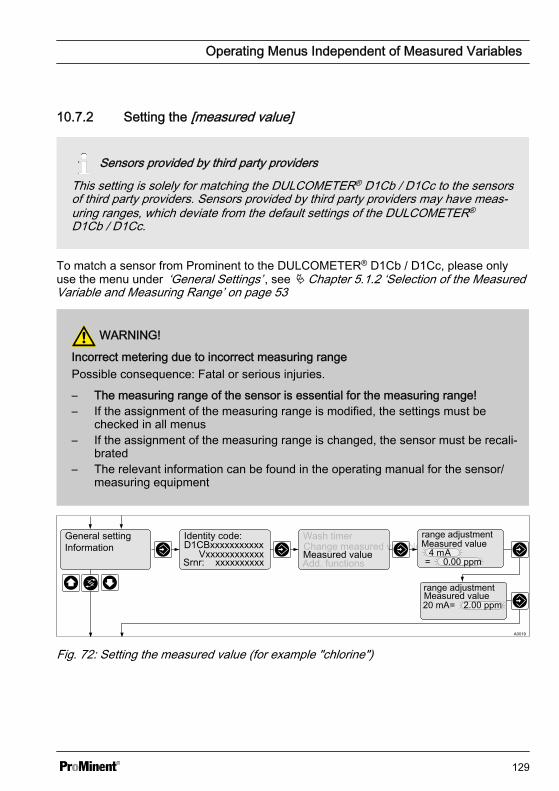
5.1.2 Selection of the Measured Variable and Measuring Range
WARNING!
Incorrect metering due to incorrect measuring rangePossible consequence: Fatal or serious injuries.
– The measuring range of the sensor is essential for the measuring range!– If the assignment of the measuring range is modified, the settings must be
checked in all menus– If the assignment of the measuring range is changed, the sensor must be recali‐
brated
With devices, which have not been preconfigured to the customer's specific requirement,the measured variable required has to be selected in the complete operating menu "Gen‐eral Settings / Change Measured Variable". The DULCOMETER® D1Cb / D1Cc then hasto be labelled with the label corresponding to the measured variable selected. The rele‐vant labels are enclosed with the DULCOMETER® D1Cb / D1Cc.
general setting Information
Identcode:
VxxxxxxxxxxxxD1CBxxxxxxxxxxx
Srnr: xxxxxxxxxxadd. functionsSoftware version
measure changewash timer chlorit
BrO3O2
effective range
A0032
0...2.00ppm
Fig. 24: Selection of measured variable and measuring rangeThe measuring range required has to be selected and set in the complete operatingmenu General Settings / Change Measured Variable, see Ä Chapter 10.7.1 ‘Setting theMeasured Variable/Measuring Range’ on page 128.
Commissioning
53
5.2 Activation Code for Extended Functions
Activation codeAccess to further functions can optionally be provided by means of an activationcode.Should you require additional operating literature for these functions, this can beobtained on the homepage of ProMinent Dosiertechnik, Heidelberg.
general settinginformationen
Identcode:
VxxxxxxxxxxD1CB xxxxxxxxx
Srnr: xxxxxxxxxxadd. functionssoftware version
measure changewach timer
functionunlocking
yes no
Code input:_ _ _ _ - _ _ _ _ -_ _ _ _ - _ _ _ _
A0010_GB
Code ok! wrong code!
Fig. 25: Activation code / Serial numberThe activation code is entered one digit at a time using the and keys. Move to thenext position using the key.
The newly activated functions must be configured or parameterised in the relevantmenu or new measured variables must be calibrated. Information on this can befound in the relevant complete operating menu.
5.2.1 Extended Functions Obtain‐able with the Activation Code
Extended functions
The DULCOMETER® D1Cb / D1Cc con‐troller functionality can be extended ormodified by means of a 16-digit activationcode. Functions can be enabled severaltimes.
D1Cb / D1Cc software upgradeTo provide an activation code, ProMi‐nent requires the 10-digit serialnumber (Srnr) and the required soft‐ware upgrade identity code, whichcan both be found in the table below.
Commissioning
54
NOTICE!
Activation codeWhen ordering the activation code, itis imperative that you ensure that theserial number (Srnr) correspondsexactly to that of the DULCOMETER®
D1Cb / D1Cc. Otherwise a charge‐able activation code will be provided,which will not work.
NOTICE!
"Incorrect code" messageIf the code has been entered incor‐rectly then the "Incorrect code" mes‐sage will appear. You can enter theactivation code as many times as youneed to. If this is still not successful,then check the serial number of thecontroller.
Commissioning
55
DULCOMETER® D1Cb / D1Cc software upgrade
D1Ub
Software default setting
V Software preset
Default setting - measured variable
0 Universal
A Peracetic acid
B Bromine
C Chlorine
D Chlorine dioxide
F Fluoride
H Hydrogen peroxide
I Chlorite
P pH
R ORP
S 0/4-20 mA standard signal general
X Oxygen
Z Ozone
L Conductivity
Connection of the measured variable
1* Standard signal 0/4-20 mA, all measured variables
5 mV input for pH/redox via guard terminal
Correction variable
0 none
2* Temperature Pt100/PT1000 (for pH and conductivity)
4* Manual temperature input (for pH and conductivity)
* = chargeable option
Commissioning
56
DULCOMETER® D1Cb / D1Cc software upgrade
Control input
0 none
1* Pause
Signal output
0 none
1* Analogue signal output 0/4-20 mA
Power activation
G Alarm and 2 limit relays
M* Alarm and 2 solenoid valve relays
Pump activation
0 none
2* 2 pumps via pulse fre‐quency
Control characteristic
0 none
1* Proportional control
2* PID control
Language
00 no defaultsetting
* = chargeable option
Commissioning
57
6 Operating diagram/ Display Symbols
6.1 Overview of equipment/Control elements
Fig. 26: Overview of equipment/Control elements
Function Description
1st respective measured variable Affix the measured variable label here.
2. Display
3. START/STOP key Start/Stop the control and metering functions
4. ENTER key To apply, confirm or save a displayed value orstatus or to acknowledge an alarm
Operating diagram/ Display Symbols
58
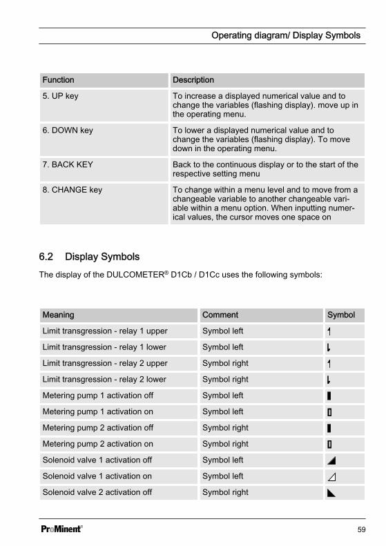
Function Description
5. UP key To increase a displayed numerical value and tochange the variables (flashing display). move up inthe operating menu.
6. DOWN key To lower a displayed numerical value and tochange the variables (flashing display). To movedown in the operating menu.
7. BACK KEY Back to the continuous display or to the start of therespective setting menu
8. CHANGE key To change within a menu level and to move from achangeable variable to another changeable vari‐able within a menu option. When inputting numer‐ical values, the cursor moves one space on
6.2 Display SymbolsThe display of the DULCOMETER® D1Cb / D1Cc uses the following symbols:
Meaning Comment Symbol
Limit transgression - relay 1 upper Symbol left
Limit transgression - relay 1 lower Symbol left
Limit transgression - relay 2 upper Symbol right
Limit transgression - relay 2 lower Symbol right
Metering pump 1 activation off Symbol left
Metering pump 1 activation on Symbol left
Metering pump 2 activation off Symbol right
Metering pump 2 activation on Symbol right
Solenoid valve 1 activation off Symbol left
Solenoid valve 1 activation on Symbol left
Solenoid valve 2 activation off Symbol right
Operating diagram/ Display Symbols
59
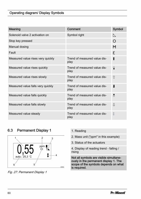
Meaning Comment Symbol
Solenoid valve 2 activation on Symbol right
Stop key pressed
Manual dosing
Fault
Measured value rises very quickly Trend of measured value dis‐play
Measured value rises quickly Trend of measured value dis‐play
Measured value rises slowly Trend of measured value dis‐play
Measured value falls very quickly Trend of measured value dis‐play
Measured value falls quickly Trend of measured value dis‐play
Measured value falls slowly Trend of measured value dis‐play
Measured value steady Trend of measured value dis‐play
6.3 Permanent Display 1
Fig. 27: Permanent Display 1
1. Reading
2. Mass unit ("ppm" in this example)
3. Status of the actuators
4. Display of reading trend - falling /rising
Not all symbols are visible simultane‐ously in the permanent display 1. Thescope of the symbols depends on whatis required.
Operating diagram/ Display Symbols
60
5. Measured variable ("chlorine" in thisexample)
6. Status line
Not all symbols are visible simultane‐ously in the permanent display 1. Thescope of the symbols depends on whatis required.
6.4 Continuous display 2
100%
2.3
A0095_GB
0%mea. valfeedfwd:ctrlout:.w = 5.0 ppm
Fig. 28: Continuous display 2The continuous display 2 shows all thecurrently required information from theDULCOMETER® D1Cb / D1Cc controller.Switch to other displays by pressing or
or .
6.5 Continuous display 3
Fig. 29: Continuous display 31. Current measured value in plain text2. Bar graph display shows the current
measured value in relation to thelower and upper measured valuelimits
3. Displays the upper and lower limit ofthe display
Switch to other displays by pressing or or .
To set the lower and upper value (3) press. The left-hand value will flash and can
be set using the or . Confirm the entrywith . Likewise, switching between theleft- and right-hand values (3) occurs bypressing the key .
This setting only changes the displayrange of the bar graph, as it were"zooming in" to a smaller range to obtain abetter resolution of the display in the maindisplay range of the measurement.
This setting only changes the displayrange of the bar graph! A change tothe measuring range of theDULCOMETER® D1Cb / D1Cc is notpossible using this function.
Operating diagram/ Display Symbols
61
6.6 Operating diagram
Access code– Access to the setting menu can be blocked with an access code– If the access code has been correctly selected for a setting menu, then all of the
other setting menus are also accessibleFundamentally the continuous displays 1 - 3 and the calibration menu are freelyaccessible. All of the other menus can be disabled by the access code in such away that the set values are displayed but cannot be changed. The default valueof the access code is "5000".
– If no key is pressed within 60 seconds, the device will return to the continuousdisplay 1, the access code is re-enabled and access is restricted
Operating diagram/ Display Symbols
62
Access code, correct
Parametersetting
Calibration notes
Permanentdisplay 1
Permanentdisplay 3
Calibrationmenu
Various
Access codeSetting menus
A0001_GB
Permanentdisplay 2
Fig. 30: Access codeThe number and scope of the setting menus depends on the design of the device.
Operating diagram/ Display Symbols
63
You can set and change numerical values as follows:
1
Text 1
Text 2Selection 1
Selection 2
Text 1
Text 2Selection 1
Selection 2
A0007_GB
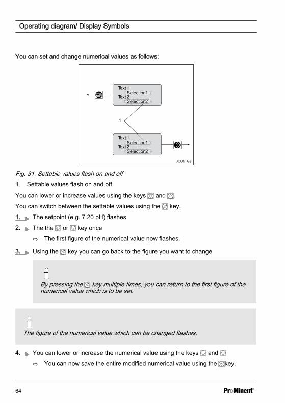
Fig. 31: Settable values flash on and off1. Settable values flash on and off
You can lower or increase values using the keys and .
You can switch between the settable values using the key.
1. The setpoint (e.g. 7.20 pH) flashes
2. The the or key once
ð The first figure of the numerical value now flashes.
3. Using the key you can go back to the figure you want to change
By pressing the key multiple times, you can return to the first figure of thenumerical value which is to be set.
The figure of the numerical value which can be changed flashes.
4. You can lower or increase the numerical value using the keys and
ð You can now save the entire modified numerical value using the key.
Operating diagram/ Display Symbols
64
5. By multiple pressing of the key you access the next menu point
6.7 Reduced / Complete Operating Menu The DULCOMETER® D1Cb / D1Cc allows settings to be made in two different compre‐hensive menus (reduced / complete). All of the parameters of the controller are presetand can be changed in the complete operating menu.
The controller is delivered with a restricted operating menu. If adjustments are neces‐sary, the parameters can be changed by switching to the complete operating menu.
general settinginformation
Identcode:D1CB xxxxxxxxxx
VxxxxxxxxxxSrnr: xxxxxxxxxxx
alarm relay
access c.: 5000
operating menu
englishreduced
A0088_GB
operating menuCalib timerwash timer
_
_
Fig. 32: Reduced / complete changeover
6.8 Fault MessagesAny fault messages and notes which ariseare shown in the bottom line of the perma‐nent display 1. Faults which have to beacknowledged (acknowledging themswitches the alarm relay off) are shown bythe symbol.
Faults/notes, which remain after acknowl‐edgement, will be displayed alternately. Ifa correction variable is being processed,the value will be displayed in the sameline as the faults/notes. Faults, which arerectified automatically by changing oper‐ating situations, are removed from thepermanent display 1 without the need foracknowledgement.
6.8.1 Fault display
Fig. 33: Fault display
1. Stop function
2. Fault
3. Fault in plain text
Operating diagram/ Display Symbols
65
6.9 Device configuration
6.9.1 Access code
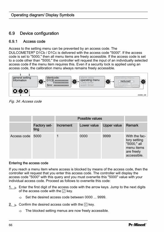
Access to the setting menu can be prevented by an access code. TheDULCOMETER® D1Cb / D1Cc is delivered with the access code "5000". If the accesscode is set to "5000," then all menu items are freely accessible. If the access code is setto a code other than "5000," the controller will request the input of an individually selectedaccess code if the menu item requires this. Even if a security lock is applied using anaccess code, the calibration menu always remains freely accessible.
general settinginformation
Identcode:D1CB xxxxxxxxxx
VxxxxxxxxxxSrnr: xxxxxxxxxxx
alarm relay
access c.: 5000
operating menu
englishreduced
A0088_GB
operating menuCalib timerwash timer
_
_
Fig. 34: Access code
Possible values
Factory set‐ting
Increment Lower value Upper value Remark
Access code 5000 1 0000 9999 With the fac‐tory setting"5000," allmenu itemsare freelyaccessible.
Entering the access code
If you reach a menu item where access is blocked by means of the access code, then thecontroller will request that you enter this access code. The controller will display theaccess code "5000" with this query and you must overwrite this "5000" value with yourindividual access code. Proceed as follows to overwrite this code:
1. Enter the first digit of the access code with the arrow keys. Jump to the next digitsof the access code with the key.
ð Set the desired access code between 0000 ... 9999.
2. Confirm the desired access code with the key.
ð The blocked setting menus are now freely accessible.
Operating diagram/ Display Symbols
66
Changing the access code
1. Select the [Operating menu] menu item with the arrow keys.
2. Press the key in the selected [Operating menu]
ð You are now taken to the sub-chapter of the operating menu.
3. Select the [Access code] menu item with the key in the [Operating menu].
ð The [Access code] menu item will start to flash.
4. Enter the first digit of the access code with the arrow keys. Jump to the next digitsof the access code with the key.
ð Set the desired access code between 0000 ... 9999.
5. Confirm the desired access code with the key.
The access code will start to flash again.
6. Confirm the desired access code with the key.
ð
Individually set access codeAn individually set access code can only be changed if this access code isknown. If this access code is no longer known, the controller can only bereset again via the customer service centre at a charge.
The new access code can now be found in the controller's memory.
Operating diagram/ Display Symbols
67
7 Measured Variables and Operating Menus for Ampero‐metric Sensors
n User qualification: instructed user,see Ä Chapter 1.2 ‘Users' qualifica‐tions’ on page 9
Measured Variables and Operating Menus for Amperometric Sensors
68
7.1 Reduced / Complete Operating Menu The DULCOMETER® D1Cb / D1Cc allows settings to be made in two different compre‐hensive menus (reduced / complete). All of the parameters of the controller are presetand can be changed in the complete operating menu.
The controller is delivered with a restricted operating menu. If adjustments are neces‐sary, the parameters can be changed by switching to the complete operating menu.
general settinginformation
Identcode:D1CB xxxxxxxxxx
VxxxxxxxxxxSrnr: xxxxxxxxxxx
alarm relay
access c.: 5000
operating menu
englishreduced
A0088_GB
operating menuCalib timerwash timer
_
_
Fig. 35: Reduced / complete changeover
7.2 Description of All Amperometric Measured Variables
WARNING!
Danger of incorrect meteringThis can result in hazardous incorrect metering
During initial commissioning, the measured variable and the measuring range of thesensor must be set prior to calibration. Refer to Ä Chapter 5.1.2 ‘Selection of theMeasured Variable and Measuring Range’ on page 53
Measured variable Default measuring range
Chlorine, chlorine dioxide, ozone 2 ppm
Bromine 10 ppm
Oxygen 20 ppm
Peracetic acid 2000 ppm
Hydrogen peroxide 200 ppm
Chlorite 0.5 ppm
Measured Variables and Operating Menus for Amperometric Sensors
69
The measuring ranges can be selected in the following ppm increments: 0.5, 2, 5, 10, 20,50, 100, 200, 1000, 2000, 5000, 10000, 20000.
7.3 Reduced Operating Menu The reduced operating menu allows the key parameters to be set. The following overviewshows the settings that can be selected:
Measured Variables and Operating Menus for Amperometric Sensors
70
Positive values of setting variable: Measured value liftNegative values of setting variable: Measured value lower
auto.: 30.0 °C
Permanent display 1
Permanent display 2only with control(w = setpoint)
Control with dead zone
For normal control
PID Control
Proportional control
Only with control
ppm0.60
mea. val 0.60ppmfeed fwd: 70 %ctrlout: 59 %w= 0.60 ppm
calibration zero p.: 4.00 mAslope:
6.50 mA/ppm
calibration DPD-value:
0.60 ppmtemp.: 30.0 °C
calibration zero p.: 4.00 mAslope:
6.75 mA/ppm
limitssetting ?
controlsetting ?
controlcontrol outputpositive negative
control
control value
set point0.60 ppm
ctrl parameterxp = 10 %
control
control value
set point 2 upper0.80 ppm
set point 1 lower0.60 ppm
controlcontrol value
30 %
manual dosing15 %
regulated range
general settinginformation
identcodeD1CBxxxxxxxxx
VxxxxxxxxxxSrnr: xxxxxxxxxx
alarm relay active
access c.: 5000
operating menu-
English- reduced
Setting incompleteoperating menu
For manual control
or
or
ctrl parameterxp = 10 %Ti = offTd = off
limit 1 lower0.10 ppm
limit 2 upper1.50 ppm
limits fault0.50 ppm
0001shyst.: ∆t off
offcontrol
A0003_GB
0.60 ppm
0.0 10.0
Permanent display 3
normal
normal
30%
30%
control value
control value
p-control
PID-control 30 %
30 %
normal
with dead band
manual
Fig. 36: Reduced operating menu
Measured Variables and Operating Menus for Amperometric Sensors
71
7.4 Complete Operating Menu / Description of All Measured VariablesThe complete operating menu allows all control unit parameters to be set. The followingoverview shows the settings that can be selected:
A0017
Metering control Set?
Continuous display 1
Measured valuedist.varCtrl.varw =
Continuous display 3
Continuous display 2Only with control(w = Setpoint)
Calibration Zero point:Slope
Only using Correcting variable
Correcting value Set?
Pumps Set?
Only with pumps
Relay Set?
Only with limit value,solenoid valve relay
Limit values Set?
Only with standard signal outputmA output Set?
General settings Information
Only with controlControl Set?
Fig. 37: Complete operating menu
Measured Variables and Operating Menus for Amperometric Sensors
72
7.5 Calibration of All Amperometric Measured Variables
WARNING!
Danger of incorrect meteringThis can result in hazardous incorrect metering
During initial commissioning, the measured variable and the measuring range of thesensor must be set prior to calibration. Refer to Ä Chapter 5.1.2 ‘Selection of theMeasured Variable and Measuring Range’ on page 53
calibration zero p.:take over value?
4.00 mA
calibration DPD-value
1.55 ppm
calibration zero p.: 4.00 mAslope
6.50 mA/ppm
calibration zero p.: 4.00 mAslope
6.50 mA/ppm
calibration Zeropoint
4.00 mA
calibration DPD-value
01.55 ppm
A0018_GB
14.00 mA
Fig. 38: Calibration of All Amperometric Measured Variables
Error message Condition Remarks *
Calibration not possible!
Gradient too low
Gradient too low
(< 20 % of standard gra‐dient)
Repeat calibration
Calibration not possible!
Gradient too high
Gradient too high
(> 300 % of standard gra‐dient)
Repeat calibration
DPD value too low
DPD > x.xx ppm
DPD < 2 % of measuringrange
Repeat calibration afteraddition of meteringmedium or fit sensor suit‐able for the process
* Please also note the operation manual for the respective sensor
Measured Variables and Operating Menus for Amperometric Sensors
73
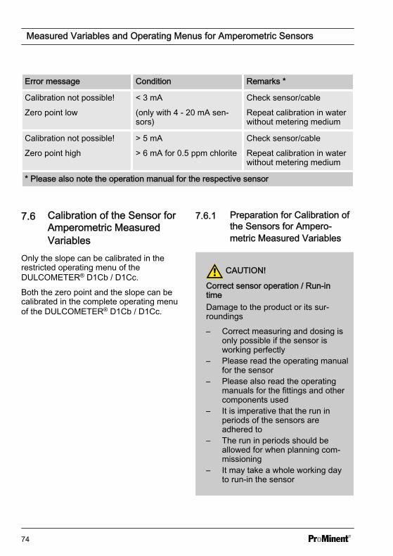
Error message Condition Remarks *
Calibration not possible!
Zero point low
< 3 mA
(only with 4 - 20 mA sen‐sors)
Check sensor/cable
Repeat calibration in waterwithout metering medium
Calibration not possible!
Zero point high
> 5 mA
> 6 mA for 0.5 ppm chlorite
Check sensor/cable
Repeat calibration in waterwithout metering medium
* Please also note the operation manual for the respective sensor
7.6 Calibration of the Sensor forAmperometric MeasuredVariables
Only the slope can be calibrated in therestricted operating menu of theDULCOMETER® D1Cb / D1Cc.
Both the zero point and the slope can becalibrated in the complete operating menuof the DULCOMETER® D1Cb / D1Cc.
7.6.1 Preparation for Calibration ofthe Sensors for Ampero‐metric Measured Variables
CAUTION!
Correct sensor operation / Run-intimeDamage to the product or its sur‐roundings
– Correct measuring and dosing isonly possible if the sensor isworking perfectly
– Please read the operating manualfor the sensor
– Please also read the operatingmanuals for the fittings and othercomponents used
– It is imperative that the run inperiods of the sensors areadhered to
– The run in periods should beallowed for when planning com‐missioning
– It may take a whole working dayto run-in the sensor
Measured Variables and Operating Menus for Amperometric Sensors
74
Necessity of calibrating the zeropointCalibration of the zero point is notgenerally necessary. Calibration ofthe zero point is only necessary if thesensor is operated at the lower limit ofthe measuring range or if the 0.5 ppmsensor version is used.
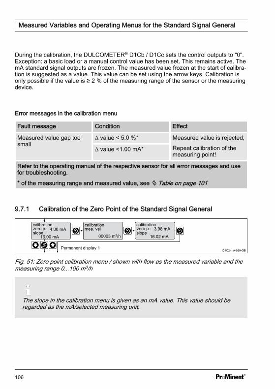
During the calibration, theDULCOMETER® D1Cb / D1Cc sets thecontrol outputs to "0". Exception: a basicload or a manual control value has beenset, this remains active. The mA standardsignal outputs are frozen. The measuredvalue frozen at the start of calibration issuggested as a DPD value. The DPDvalue can be set using the arrow keys.Calibration is only possible if the DPDvalue is ≥ 2 % of the measuring range ofthe sensor.
7.6.2 Calibration of Zero Point andSlope
NOTICE!
Prerequisites for correct calibration ofthe sensor slope– The DPD method required by the
feed chemical employed will beused
– The run in period for the sensorhas been adhered to
– There is permitted and constantflow at the in-line probe housing
– There is temperature balancebetween the sensor and thesample water
– There is a constant pH value inthe permitted range
Measured Variables and Operating Menus for Amperometric Sensors
75
Calibration of amperometric sensors:slope (in the reduced and complete oper‐ating menu)
The sensor is fitted, flushed with samplewater and connected electrically to theDULCOMETER® D1Cb / D1Cc and run-in.
There has to be adequate feed chemicalin the sample water for calibration (> 2%of the measuring range of the sensor).
Remove sample water directly at themeasuring point and determine the con‐tent of metering medium in the samplewater in "ppm" using an appropriate refer‐ence method (e.g. DPD, titration etc.).Enter this value as follows at theDULCOMETER® D1Cb / D1Cc:
1. Select Calibration menu. Thenpress
ð The current measured valuewill now be frozen.
2. Take a sample of water and per‐form a reference measurementwithin 15 minutes
3. Select "DPD value" of unit to becalibrated using the key
4. Continue with
5. If necessary, match the flashingppm value to the value determinedwith the measurement using thekeys, , and
ð The mA value of the sensorshown in this display now cor‐responds to the measuredvalue in "ppm".
6. Then press the following key twice
ð The display now shows thevalue determined for the zeropoint and slope. Refer to theError Message table should anerror be dis‐played.Ä Table on page 73
Necessity of calibrating the zeropointCalibration of the zero point is notgenerally necessary. Calibration ofthe zero point is only necessary if thesensor is operated at the lower limit ofthe measuring range or if the 0.5 ppmsensor version is used.
Measured Variables and Operating Menus for Amperometric Sensors
76
Calibration of amperometric sensors: Zeropoint (only in the complete operatingmenu)
A container with water, which is free ofadditives that could falsify the measuredresult, is needed for calibration. Immersethe dismounted, but still electrically con‐nected to theDULCOMETER® D1Cb / D1Cc, sensor inthis water. Use the sensor to stir the waterfor approx. 5 minutes until the measuredvalue displayed at theDULCOMETER® D1Cb / D1Cc is steadyand close to "0".
1. Select Calibration menu. Thenpress
2. Select "Zero point" of unit to be cali‐brated using the key
3. Continue with
ð A prompt is shown in the dis‐play
4. Confirm prompt with the key
5. Continue with
6. Apply the "zero point" displayedduring calibration using the key
7. Then press
ð Display shows the valuesdetermined.
8. Then press
ð Refer to the Error Messagetable should an error be dis‐played.Ä Table on page 73
NOTICE!
Then definitively calibrate the slopewith a suitable reference method (e.g.DPD. titration etc.).
Measured Variables and Operating Menus for Amperometric Sensors
77
7.7 Correcting value
Only necessary when using the DULCOTEST® CDP sensor for chlorine dioxideClO2.
only with correction valuecorrection valuesetting ?
correcting valuetemperatureautomatic
A0020_GB
Fig. 39: Correcting valueThe correction variable compensates for the effect of the temperature of the medium onthe measured value. The correction variable is the temperature of the medium to bemeasured. The temperature of the medium affects the value to be measured. Foramperometric sensors only necessary when using the DULCOTEST® CDP sensor forchlorine dioxide ClO2.
Operating modes
n Off: No temperature compensation takes place.– For measurements which do not require temperature compensation.
n Automatic: The DULCOMETER® D1Cb / D1Cc evaluates the temperature signal ofthe connected temperature sensor.– For measurements with temperature sensors, which deliver a temperature signal
which can be evaluated by the DULCOMETER® D1Cb / D1Cc (Pt100/Pt1000) (0-100 °C).
n Manual: The temperature of the medium to be measured has to be measured by theuser. The measured value is then entered using the keys: , and into theDULCOMETER® D1Cb / D1Cc and saved by pressing the key .– For measurements where the medium to be measured has a constant tempera‐
ture, which has to be taken into account in the control process.
Measured Variables and Operating Menus for Amperometric Sensors
78
8 Measured Variables and Operating Menus for Potentio‐metric Sensors
n User qualification: instructed user,see Ä Chapter 1.2 ‘Users' qualifica‐tions’ on page 9
Measured variables pH, ORP, fluoride
CAUTION!
Influence of temperature on the pH orfluoride measurementPossible consequence: Slight orminor injuries. Material damage.
Temperature changes in the samplewater lead to a change in the slope ofthe calibration lines (pH, fluoride) andto a displacement of the zero pointwith pH sensors or the standardpotential ES for fluoride sensors.
Measure to be taken to avoid thisdanger:
– The pH or fluoride measurementshould only be carried out in the[Temperature Correction Valueautomatic] setting
– The DULCOMETER® D1Cb /D1Cc then automatically compen‐sates for both effects when con‐necting a temperature sensor(Pt 100/Pt 1000)
Measured Variables and Operating Menus for Potentiometric Sensors
79
8.1 Reduced / Complete Operating Menu The DULCOMETER® D1Cb / D1Cc allows settings to be made in two different compre‐hensive menus (reduced / complete). All of the parameters of the controller are presetand can be changed in the complete operating menu.
The controller is delivered with a restricted operating menu. If adjustments are neces‐sary, the parameters can be changed by switching to the complete operating menu.
general settinginformation
Identcode:D1CB xxxxxxxxxx
VxxxxxxxxxxSrnr: xxxxxxxxxxx
alarm relay
access c.: 5000
operating menu
englishreduced
A0088_GB
operating menuCalib timerwash timer
_
_
Fig. 40: Reduced / complete changeover
8.2 Description of pH, Redox and Fluoride Measured Variables
WARNING!
Danger of incorrect meteringThis can result in hazardous incorrect metering
During initial commissioning, the measured variable and the measuring range of thesensor must be set prior to calibration. Refer to Ä Chapter 5.1.2 ‘Selection of theMeasured Variable and Measuring Range’ on page 53
pH Measured variable Typical measuring range
Measuring range - 500 mV … + 500 mV
Display range At least pH -1.45 … 15.45
Reference temperature +25°C
Resolution 0.01 pH
Measured Variables and Operating Menus for Potentiometric Sensors
80
Redox measured variable Typical measuring range
Measuring range -1000 mV … + 1000 mV
Resolution 1 mV
Fluoride measured variable Measuring range
Measuring range 0....10 ppm
0.... 99.99 ppm
Resolution 0.01 ppm
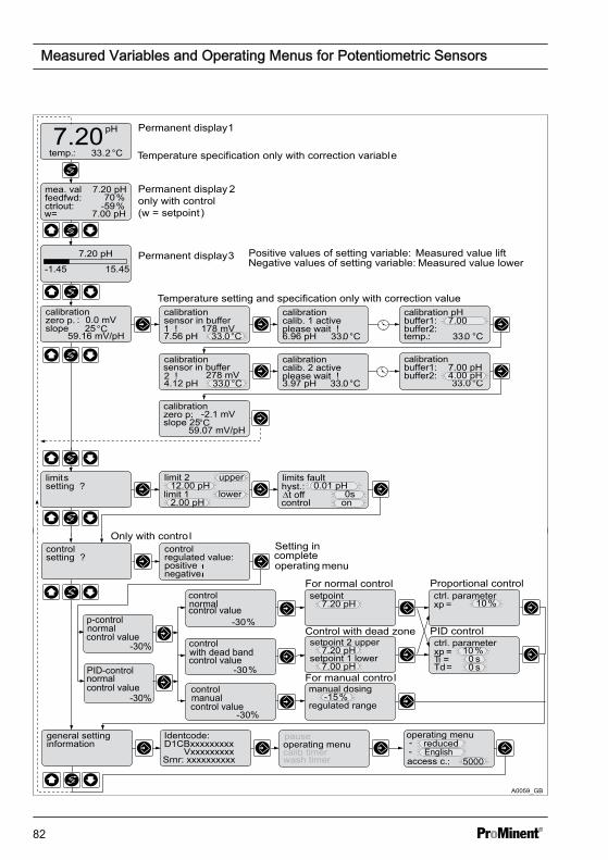
8.3 Reduced pH / Redox / Fluoride Operating Menu The reduced operating menu allows the key parameters to be operated. The followingoverview shows the settings that can be selected (shown here for pH as the measuredvariable):
Measured Variables and Operating Menus for Potentiometric Sensors
81
Permanent display 1
Permanent display 2only with control(w = setpoint )
Temperature specification only with correction variabletemp.: 33.2°C
pH7.20
Temperature setting and specification only with correction valuecalibration zero p. :slope 25°C
Positive values of setting variable:Negative values of setting variable:
w= 7.00 pH
limit 1 lower
limit 212.00 pH
upper
2.00 pH
control
-30 %
control
-30 %
Control with dead zone
For normal control
PID control
Proportional controlsetpoint
7.20 pH
ctrl. parameter
Ti =Td =
xp =
ctrl. parameterxp = 10 %
controlsetting ?
control
positive regulated value:
negative
manual dosing
control
-30 %
-15 %regulated range
general settinginformation
Identcode:
VxxxxxxxxxD1CBxxxxxxxxx
Srnr: xxxxxxxxxx
operating menu
access c.:--operating menupause
5000
For manual control
setpoint 2 upper
setpoint 1 lower7.20 pH
7.00 pH
Setting incompleteoperating menu
Only with contro l
reduced
0 s
10 %0 s
A0059_GB
Measured value liftMeasured value lower
limits fault0.01 pH
0shyst.: ∆t off
oncontrol
7.20 pH
15.45 -1.45Permanent display 3
calib timerwash timer
sensor in buffer
178 mV
278 mV
English
normal
normal
-30%
-30%
control value
control value
p-control
PID-control
control value
control value
control value
with dead band
normal
manual
Measured Variables and Operating Menus for Potentiometric Sensors
82
Fig. 41: Reduced pH / redox / fluoride operating menu (shown with the example of pH)
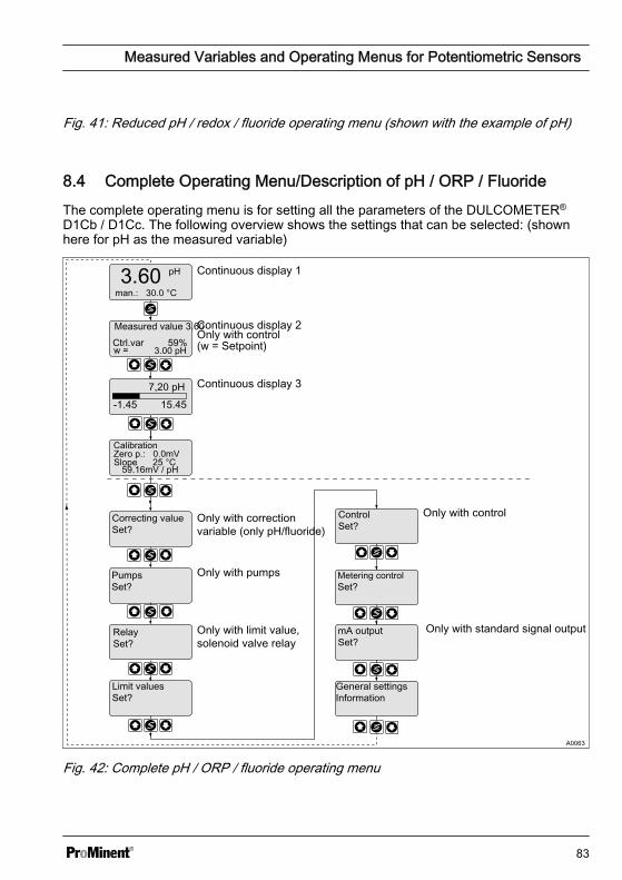
8.4 Complete Operating Menu/Description of pH / ORP / FluorideThe complete operating menu is for setting all the parameters of the DULCOMETER®
D1Cb / D1Cc. The following overview shows the settings that can be selected: (shownhere for pH as the measured variable)
A0063
man.: 30.0 °C
w =
Slope 25 °C59.16mV / pH
Metering control Set?
7,20 pH15.45 -1.45
Only with correction variable (only pH/fluoride)
Continuous display 1
Continuous display 2
Continuous display 3
Only with control(w = Setpoint)
Zero p.: 0.0mV
Correcting value Set?
Only with pumpsPumps Set?
Relay Set?
Only with limit value,solenoid valve relay
Limit values Set?
Only with standard signal outputmA output Set?
General settingsInformation
Measured value 3.60 Ctrl.var 59%
Calibration
Control Set?
Only with control
Fig. 42: Complete pH / ORP / fluoride operating menu
Measured Variables and Operating Menus for Potentiometric Sensors
83
8.5 Calibration of pH, ORP andFluoride Sensors
WARNING!
Incorrect metering due to incorrectmetering rangePossible consequence: Fatal orserious injuries.
– The measuring range of thesensor is essential for the meas‐uring range!
– If the assignment of the meas‐uring range is modified, the set‐tings must be checked in allmenus
– If the assignment of the meas‐uring range is changed, thesensor must be recalibrated
CAUTION!
Correct sensor operation / Run-intimeDamage to the product or its sur‐roundings
– Correct measuring and dosing isonly possible if the sensor isworking perfectly
– Please read the operating manualfor the sensor
– It is imperative that the run inperiods of the sensors areadhered to
– The run in periods should beallowed for when planning com‐missioning
During calibration, the DULCOMETER®
D1Cb / D1Cc, see Ä Chapter 1.2 ‘Users'qualifications’ on page 9 sets the controloutputs to ‘0’ . Exception: a basic load ora manual control value has been set. Thisremains active. The mA standard signaloutputs are frozen.
When calibration/testing has been com‐pleted successfully, all of the error checksrelating to the measured value arerestarted. The DULCOMETER®
D1Cb / D1Cc stores the determined datafor zero point and slope. Refer toÄ Chapter 10.7.3.7 ‘Calibration Logbook ’on page 131
Measured Variables and Operating Menus for Potentiometric Sensors
84
8.5.1 Description of the Calibration of pH Sensors
8.5.1.1 2-Point Calibration
2-Point CalibrationRecommended as the standard method
Calibration of pH sensors with temperature as the correction variableWhen calibrating with temperature as the correction variable, the temperature of thebuffer solution must be set in "manual" operating mode before calibration.In "Automatic" operating mode, the temperature sensor must be immersed in thebuffer solution. The calibration values are then calculated whilst taking into consider‐ation the buffer temperature.
Temperature setting and specification only with correction valuecalibration pHzero p.:slope 25°C
calibration calib. 2 activeplease wait !3.97 pH 33.0 °C
calibration buffer1:buffer2:
33.0 °C
7.00 pH4.00 pH
calibration
2 !4.12 pH 33.0°C
= automatic timing
Permanent display 1
sensor in buffer
A0060_GB
7.00 pH
Fig. 43: Calibration of pH sensors
Measured Variables and Operating Menus for Potentiometric Sensors
85
Two test containers with a buffer solution are required for calibration. The pH value of thebuffer solutions should be at least 2 ph values apart. The sensor should be rinsed thor‐oughly with water when changing the buffer solution.
1. Select Calibration menu
2. Immerse sensor in test container 1 with buffer solution (e.g. pH 7)
3. Move the sensor gently until the pH value displayed no longer changes
4. Then press
ð Calibration is running
A buffer value is suggested once the waiting time has expired.
5. If necessary adjust the pH value displayed using keys , and to the actualvalue of the buffer solution in test container 1
6. Then press
7. Remove the sensor, rinse thoroughly in water and then dry with a cloth (pad dry,don't rub!)
8. Immerse sensor in test container 2 with buffer solution (e.g. pH 4)
9. Move the sensor gently until the pH value displayed no longer changes
10. Then press
ð Calibration is running
A buffer value is suggested once the waiting time has expired.
11. If necessary adjust the pH value displayed using keys , and to the actualvalue of the buffer solution in test container 2
12. Then press
ð The settings recorded will be displayed.
13. If the calibration result is correct, confirm with
ð The new calibration is now applied.
Should the result of the calibration lie outside of the specified error limits, an error mes‐sage will appear, see Ä Chapter 8.5.3 ‘Calibration of pH Sensors. Description of theError Messages ’ on page 88. In this case the current calibration will not be applied.
Measured Variables and Operating Menus for Potentiometric Sensors
86
8.5.1.2 1-Point Calibration
1-Point CalibrationRecommended only for special appli‐cations e.g swimming pool water
Calibration of pH sensors withtemperature as the correction variableWhen calibrating with temperature asthe correction variable, the tempera‐ture of the buffer solution must be setin "manual" operating mode beforecalibration.In "Automatic" operating mode, thetemperature sensor must beimmersed in the buffer solution. Thecalibration values are then calculatedwhilst taking into consideration thebuffer temperature.
One test container with a buffer solution isrequired for calibration.
1. Select Calibration menu
2. Immerse the sensor in the test con‐tainer with buffer solution (e.g. pH7)
3. Move the sensor gently until the pHvalue displayed no longer changes
4. Then press
ð Calibration is running
A buffer value is suggestedonce the waiting time hasexpired.
5. If necessary adjust the pH valuedisplayed using keys , and to the actual value of the buffer sol‐ution in the test container
6. Then press
7. Then press
ð The settings recorded will bedisplayed.
8. If the calibration result is correct,confirm with
ð The new calibration is only nowapplied.
Should the result of the calibration lie out‐side of the specified error limits, an errormessage will appear, see Ä Chapter 8.5.3‘Calibration of pH Sensors. Description ofthe Error Messages ’ on page 88. In thiscase the current calibration will not beapplied.
Measured Variables and Operating Menus for Potentiometric Sensors
87
8.5.2 Calibration of pH Sensors. Description of the Setting Ranges
Setting Possible values
Startingvalue
Increment Lower value Upper value Remarks
Calibrationtemperature
Reading 0.1 0 °C 100
Buffervalues
Reading(whole digitrounded up)
0.01 pH -1.45 pH 15.45 pH Error mes‐sage if thetwo bufferslie too closeto eachother (<2 pHvalues)
8.5.3 Calibration of pH Sensors. Description of the Error Messages
Error message Condition Effect
Buffer gap too small ∆buffer <2 pH During the calibration process: recalibratebuffer 2!
Back to the permanent display
pH zero point low < -60 mV Basic load metering Note: old zero point andgradient remain
pH zero point high > +60 mV Basic load metering Note: old zero point andgradient remain
pH gradient low < 40 mV/pH Basic load metering Note: old zero point andgradient remain
pH gradient high > 65mV/pH Basic load metering Note: old zero point andgradient remain
pH readingunsteady
Note: old zero point andgradient remain
°C readingunsteady
Note: old zero point andgradient remain
The following applies to all error messages: eliminate the source of the error andrepeat calibration.
Measured Variables and Operating Menus for Potentiometric Sensors
88
8.5.4 Testing the Redox Sensor
CAUTION!
Correct sensor operation / Run-in timeDamage to the product or its surroundings
– Correct measuring and metering is only possible if the sensor is working per‐fectly
– Please read the operating manual for the sensor– It is imperative that the run-in times of the sensors are adhered to– The run-in times should be allowed for when planning initial operation
NOTICE!
Testing the Redox SensorWith redox measured variables, the sensor is not calibrated but tested according toits design
– Observe any notification of abnormal behaviour when testing the redox sensor– Should the test not be successful, replace the redox sensor
= automatic timing
check sensorORP
check sensorORPsensor in buffer r460 mV
check sensormeasuremactiveplease wait!
check sensorORPmea. valbuffer
460 mV465 mV
permanent display 1 A0064_GB
460 mV
Fig. 44: Testing redox sensors
8.5.4.1 Description of the Testingof Redox Sensors
A container with a redox buffer solution(e.g. 465 mV) is needed for testing.
1. Select the Test menu
Measured Variables and Operating Menus for Potentiometric Sensors
89
2. Immerse redox sensor in the testcontainer with redox buffer solution(e.g. 465 mV)
3. Start test with
ð Test is running.
A buffer value is suggestedonce the waiting time hasexpired.
4. Adjust displayed value of "buffer"(flashing) using , and to themV value of the redox buffer solu‐tion in the test container and con‐firm the value with
ð The D1Cb displays the statusmessage of the redox sensor inplain text. If the redox sensor isfunctioning correctly, perma‐nent display 1 will be displayeddirectly
5. If the redox sensor is unclean ordefective, the redox sensor shouldbe cleaned, as described in theredox sensor operating manual, oralternatively replaced
Should the result of the calibration lie out‐side of the specified error limits, an errormessage will appear, seeÄ Chapter 8.5.4.3 ‘Testing Redox Sen‐sors. Description of the Error Messages ’on page 91
Measured Variables and Operating Menus for Potentiometric Sensors
8.5.4.3 Testing Redox Sensors. Description of the Error Messages Table: Possible error messages when testing redox sensors
Error message Condition Effect
Reading high Reading
40 mV> buffer
Back to the permanent dis‐play
Basic load metering
Reading low Reading
40 mV< buffer
Back to the permanent dis‐play
Basic load metering
Measured Variables and Operating Menus for Potentiometric Sensors
91
8.5.5 Description of the Calibration of Fluoride Sensors
Temperature setting and specification only with correction valuecalibration
slope 1.00ppm= 184.4mV
59.16 mV/dec
calibration
57.81 mV/dec
calibration sensor insolut. 1mea. val 1.7 ppm170.3 mV
calibration calib. 1 activeplease wait !170.3mV 33.0 °C
calibration solut. 1
33.0 °C
calibration calib. 2 activeplease wait !3.97 mV 33.0 °C
calibration
33. 0 °C
1.7 ppm7.8 ppm
calibration
mea. val 7.8ppm132.0 mV
= automatic timing
Permanent display 1
sensor insolut. 2
A0202 _GB
1.7 ppmsolut. 2
solut. 1solut. 2
slope 1.00ppm= 183.5mV
Fig. 45: Calibrating the fluoride sensor
8.5.5.1 Description of the Calibra‐tion of Fluoride Sensors
Temperature correction variableWhen calibrating with temperature asthe correction variable, the tempera‐ture of the buffer solution has to beset. in "manual" operating modebefore calibration. Refer toÄ Chapter 8.6 ‘Temperature correc‐tion value for pH and fluoride sensors’on page 96In "Automatic" operating mode, thetemperature sensor must beimmersed in the buffer solution. Thecalibration values are then calculatedallowing for the temperature.
8.5.5.1.1 Description of 2-Point Cal‐ibration for Fluoride Sen‐sors
Material required for calibration of fluoridesensors
n Two test containers with calibratingsolution
n A thermometer for measuring in fluids(in "Temperature Correction Valuemanual" operating mode)
Two test containers with calibrating solu‐tion are required for calibration. The fluo‐ride content of the calibrating solutionsshould be at least 0.5 ppm F apart fromeach other. The sensor should be rinsedthoroughly with fluoride-free water whenchanging the calibrating solution.
1. Select Calibration menu
ð In "Temperature CorrectionValue manual" operating mode,the calibration display appearsand the temperature valueflashes.
Measured Variables and Operating Menus for Potentiometric Sensors
92
In "Temperature CorrectionValue automatic" operatingmode the calibration displayappears
2. Measure the temperature of the cal‐ibrating solution 1 using the ther‐mometer (only in "TemperatureCorrection Value manual" operatingmode)
3. Enter the determined value for thecalibration solution temperatureusing the keys , and intothe DULCOMETER® D1Cb / D1Cc
4. Confirm entry with the key
ð The DULCOMETER®
D1Cb / D1Cc allows for theactual temperature of the cali‐bration solution during the cali‐bration.
5. Immerse the fluoride sensor in cali‐bration solution 1 and wait until themV value displayed remains steady(fluctuation of < 0.05 mV/min)
6. Start the calibration process bypressing
ð Calibration is running
7. Using the keys , and enterthe determined concentration forthe calibration solution in ppm intothe DULCOMETER® D1Cb / D1Cc
8. Confirm the ppm value by pressing
ð In "Temperature CorrectionValue manual" operating mode,the calibration display appearsand the temperature valueflashes.
In "Temperature CorrectionValue automatic" operatingmode the calibration displayappears
9. Measure the temperature of the cal‐ibrating solution 2 using the ther‐mometer (only in "TemperatureCorrection Value manual" operatingmode)
10. Prepare for calibration in calibratingsolution 2
11. Enter the determined value for thecalibration solution temperatureusing the keys , and intothe DULCOMETER® D1Cb / D1Cc
12. Confirm entry with the key
ð The DULCOMETER®
D1Cb / D1Cc allows for theactual temperature of the cali‐bration solution during the cali‐bration.
13. The fluoride sensor should berinsed thoroughly with fluoride-freewater when changing the calibratingsolution
14. Immerse the fluoride sensor in cali‐bration solution 2 and wait until themV value displayed remains steady(fluctuation of < 0.05 mV/min)
15. Start the calibration process bypressing
ð Calibration is running.
16. Using the keys , and enterthe determined concentration forthe calibration solution in ppm intothe DULCOMETER® D1Cb / D1Cc
17. Confirm the ppm value by pressing
Measured Variables and Operating Menus for Potentiometric Sensors
93
ð The display of theDULCOMETER® D1Cb / D1Ccshows the result of the calibra‐tion. If the calibration result iscorrect, confirm by pressing .
8.5.5.1.2 1-Point Calibration of theFluoride Sensor
Calibration of fluoride. Description of 1-point calibration
One container with a calibrating solution isrequired for calibration.
1. Select Calibration menu
ð In "Temperature CorrectionValue manual" operating mode,the calibration display appearsand the temperature valueflashes.
In "Temperature CorrectionValue automatic" operatingmode the calibration displayappears
2. Measure the temperature of the cal‐ibrating solution 1 using the ther‐mometer (only in "TemperatureCorrection Value manual" operatingmode)
3. Enter the determined value for thecalibration solution temperatureusing the keys , and intothe DULCOMETER® D1Cb / D1Cc
4. Confirm entry with the key
ð The DULCOMETER®
D1Cb / D1Cc allows for theactual temperature of the cali‐bration solution during the cali‐bration.
5. Immerse the fluoride sensor in cali‐brating solution 1 and wait until themV value displayed remains steady(fluctuation of < 0.05 mV/min)
6. Start the calibration process bypressing
ð Calibration is running
Measured Variables and Operating Menus for Potentiometric Sensors
94
7. Using the keys , and enterthe determined concentration forthe calibration solution in ppm intothe DULCOMETER® D1Cb / D1Cc
8. Confirm the ppm value by pressing
Measured Variables and Operating Menus for Potentiometric Sensors
95
8.6 Temperature correction value for pH and fluoride sensors
CAUTION!
Influence of temperature on the pH or fluoride measurementPossible consequence: Slight or minor injuries. Material damage.
Temperature changes in the sample water lead to a change in the slope of the cali‐bration lines (pH, fluoride) and to a displacement of the zero point with pH sensors orthe standard potential ES for fluoride sensors.
Measure to be taken to avoid this danger:
– The pH or fluoride measurement should only be carried out in the[Temperature Correction Value automatic] setting
– The DULCOMETER® D1Cb / D1Cc then automatically compensates for botheffects when connecting a temperature sensor (Pt 100/Pt 1000)
only with correction valuecorrection valuesetting ?
correcting valuetemperatureautomatic
A0020_GB
Fig. 46: Temperature correction value for pH and fluoride sensors
Temperature correction value for pH and fluoride sensors in line with the identity code:
Possible values
As per identity code Increment Lower value Upper value
0 off
2 off
Manual
Automatic
4 off
Manual
Measured Variables and Operating Menus for Potentiometric Sensors
96
Temperature correction value for pH and fluoride sensors
Possible values
Factory setting Increment Lower value Upper value
Manual temperaturecompensation
25 °C 0.1 °C 0 °C 100 °C
Measured Variables and Operating Menus for Potentiometric Sensors
97
9 Measured Variables and Operating Menus for the StandardSignal General
n User qualification: instructed user,see Ä Chapter 1.2 ‘Users' qualifica‐tions’ on page 9
9.1 Explanation of the StandardSignal General
The measured variable "Standard SignalGeneral" of the DULCOMETER® D1Cb /D1Cc is used to connect sensors fromthird party providers, which send a linearmA signal, to the DULCOMETER® D1Cb /D1Cc. The DULCOMETER® D1Cb / D1Ccis thus preconditioned to be able tomeasure and control a number of physicalmeasured variables, using appropriatesensors, see Ä Table on page 101.
Adjusting the sensor output signal
To match the DULCOMETER® D1Cb /D1Cc to the output signal from the sensoror measuring device you must carry outthe following steps:
NOTICE!
Linear characteristic lineAs the DULCOMETER® D1Cb / D1Cccan only process linear characteristiclines, only sensors/measuring devicescan be connected, which emit a linearsignal.
1. Changing the DULCOMETER®
D1Cb / D1Cc over to the completeoperating menu
2. Set the required physical unit(measured variable)
Display tolerancesWith sensors or with output signals ofmeasuring devices, which do nothave to be calibrated or with whichcalibration has to be done in thesensor/measuring device, the displaytolerances must then be calibratedbetween the sensor or measuringdevice and the DULCOMETER®
D1Cb / D1Cc.
3. To do so, select the menu "Setmeasured value", see .
Measured Variables and Operating Menus for the Standard Signal General
98
4. The measuring range limit of 0/4mA and 20 mA can be adjusted byraising and/or lowering the meas‐ured values
ð The limits of the measuringrange are adjusted in order tocalibrate the display tolerancebetween the sensor or meas‐uring device and theDULCOMETER® D1Cb.
NOTICE!
CalibrationProMinent also offers the possibility ofone-point or two-point calibration ofthe "standard signal general" meas‐ured variable. This calibration optionshould only be used if the manufac‐turer of the sensor or measuringequipment describes or permits this inthe operating manual for the sensoror measuring equipment.
Measured Variables and Operating Menus for the Standard Signal General
99
9.2 Changing the Measured Variable
WARNING!
Incorrect metering due to incorrect measured variablePossible consequence: Fatal or serious injuries
– The measured variable/measuring range of the sensor is essential for the meas‐ured variable/measuring range!
– If the measured variable/measuring range is changed, the sensor must be recali‐brated
– If the measured variable/measuring range is changed, the set points and limitvalues will be changed to the associated starting values!
– If the measured variable/measuring range is changed, the settings in all of themenus must be checked
general settinginformationen
Identcode:
VxxxxxxxxxxD1CBxxxxxxx
Srnr: xxxxxxxxxx
Calib. timer
effective range0...105 %
A0232_GB
wash timermeasure changeadd. functions
PAAH2O2 (PER)mA generalpH over mA
Fig. 47: Changing "Standard signal general" measured variableFor possible measured variables see Ä Table on page 101.
Measured Variables and Operating Menus for the Standard Signal General
100
9.3 Reduced / Complete Operating Menu The DULCOMETER® D1Cb / D1Cc allows settings to be made in two different compre‐hensive menus (reduced / complete). All of the parameters of the controller are presetand can be changed in the complete operating menu.
The controller is delivered with a restricted operating menu. If adjustments are neces‐sary, the parameters can be changed by switching to the complete operating menu.
general settinginformation
Identcode:D1CB xxxxxxxxxx
VxxxxxxxxxxSrnr: xxxxxxxxxxx
alarm relay
access c.: 5000
operating menu
englishreduced
A0088_GB
operating menuCalib timerwash timer
_
_
Fig. 48: Reduced / complete changeover
9.4 Description of All Standard Signal Measured Values/MeasuredVariables
Possible values
Measured vari‐able
Increment Lower value Upper value Measuringrange*
Measuringsignal
0.1% -5,0 % 105,0 % 100 %
0.01 mA -1.00 mA 21.00 mA 20 mA
Filling level 0.01 m 0.00 m 31.50 m 30 m
0.1 % 0.0 % 105,0 % 100 %
Pressure 0.001 bar 0.000 bar 1.050 bar 1.000 bar
0.001 bar 0.000 bar 5.250 bar 5.000 bar
0.01 bar 0.00 bar 10.50 bar 10.00 bar
0.1 bar 0.0 bar 105.0 bar 100.0 bar
0.1 psi 0.0 psi 105.0 psi 100 psi
1 psi 0 psi 1050 psi 1000 psi
* Maximum set point that can be set
Measured Variables and Operating Menus for the Standard Signal General
101
Possible values
Measured vari‐able
Increment Lower value Upper value Measuringrange*
Flow rate 0.001 m 3 /h 0.000 m 3 /h 10.00 m 3 /h 9.999 m 3 /h
0.1 m 3 /h 0.0 m 3 /h 105.0 m 3 /h 100 m 3 /h
1 m 3 /h 0 m 3 /h 1,050 m 3 /h 1,000 m 3 /h
0.1 gal/h 0.0 gal/h 105.0 gal/h 100 gal/h
1 gal/h 0 gal/h 1050 gal/h 1000 gal/h
Concentration 1 ppm 0 ppm 1050 ppm 1000 ppm
Relativehumidity
0.1 % rel.humidity
0.0 % rel.humidity
105.0 % rel.humidity
100 % rel.humidity
mA signal 0.01 mA 0.00 mA 21.00 mA 20 mA
0.01 mA 4.00 mA 21.00 mA 20 mA
Turbidity value 1 NTU 0 NTU 10 NTU 10 NTU
1 NTU 0 NTU 105 NTU 100 NTU
1 NTU 0 NTU 2100 NTU 2000 NTU
* Maximum set point that can be set
9.5 Reduced Operating Menu The reduced operating menu allows the key parameters to be set. The following overviewshows the settings that can be selected:
Measured Variables and Operating Menus for the Standard Signal General
102
Positive values of setting variable: Measured value liftNegative values of setting variable: Measured value lower
auto.: 30.0 °C
Permanent display 1
Permanent display 2only with control(w = setpoint)
Control with dead zone
For normal control
PID Control
Proportional control
Only with control
%0.60
mea. val 0.60feed fwd: 70 %ctrlout: 59 %w= 0.60 ppm
calibration zero p.: 4.00 mAslope:
1.40 mA
calibration mea. val
calibration zero p.: 4.00 mAslope:
0.11 mA
limitssetting ?
controlsetting ?
controlcontrol outputpositive negative
control
control value
set point50 %
ctrl parameterxp = 10 %
control
control value
set point 2 upper30 %
set point 1 lower28%
control
control value30 %
manual dosing15 %
regulated range
general settinginformation
identcodeD1CBxxxxxxxxx
VxxxxxxxxxxSrnr: xxxxxxxxxx
alarm relay active
access c.: 5000
operating menu-
English- reduced
Setting incompleteoperating menu
For manual control
or
or
ctrl parameterxp = 10 %Ti = offTd = off
limit 1 lower21 %
limit 2 upper84 %
limits fault1.50 %
0001shyst.: ∆t off
offcontrol
D1C2-mA-010-GB
0.60 %
0.0 10.0
Permanent display 3
normal
normal
30%
30%
control value
control value
p-control
PID-control 30 %
30 %
normal
with dead band
manual
-21%
Fig. 49: Reduced operating menu / Shown with measured variable % and the measuringrange 0%....100%
Measured Variables and Operating Menus for the Standard Signal General
103
9.6 Complete Operating Menu / Description of All Measured VariablesThe complete operating menu allows all control unit parameters to be set. The followingoverview shows the settings that can be selected:
Slope
Metering control Set?
Only with correction variable (only pH/fluoride)
Continuous display 1
Continuous display 2
Continuous display 3
Only with control(w = Setpoint)
Zero p.: 4.00 mA
Correcting value Set?
Only with pumpsPumps Set?
Relay Set?
Only with limit value,solenoid valve relay
Limit values Set?
Only with control
Only with standard signal outputmA output Set?
General settings Information
Measured valueCtrl.var
Calibration
Control Set?
Fig. 50: Complete operating menu / Shown with measured variable % and the measuringrange 0%....100%
9.7 Calibrating the Standard Signal In the restricted operating menu: The DULCOMETER® D1Cb / D1Cc calibrates the zeropoint.
Measured Variables and Operating Menus for the Standard Signal General
104
In the complete operating menu: The DULCOMETER® D1Cb / D1Cc carries out a two-point calibration.
WARNING!
Incorrect metering due to incorrect metering rangePossible consequence: Fatal or serious injuries
– The measuring range of the sensor or the measuring device is essential for themeasuring range!
– If the assignment of the measuring range is modified, the settings must bechecked in all menus
– If the assignment of the measuring range is changed, the sensor or the meas‐uring device must be recalibrated
CAUTION!
Correct sensor operation / Run-in timeDamage to the product or its surroundings
– Correct measuring and dosing is only possible if the sensor is working perfectly– Please read the operating manual for the sensor or the measuring device– It is imperative that the run in periods of the sensors or the measuring device are
adhered to– The run in periods should be allowed for when planning commissioning– It may take a whole working day to run-in the sensor or the measuring device
Measured Variables and Operating Menus for the Standard Signal General
105
During the calibration, the DULCOMETER® D1Cb / D1Cc sets the control outputs to "0".Exception: a basic load or a manual control value has been set. This remains active. ThemA standard signal outputs are frozen. The measured value frozen at the start of calibra‐tion is suggested as a value. This value can be set using the arrow keys. Calibration isonly possible if the value is ≥ 2 % of the measuring range of the sensor or the measuringdevice.
Error messages in the calibration menu
Fault message Condition Effect
Measured value gap toosmall
∆ value < 5.0 %* Measured value is rejected;
Repeat calibration of themeasuring point!
∆ value <1.00 mA*
Refer to the operating manual of the respective sensor for all error messages and usefor troubleshooting.
* of the measuring range and measured value, see Ä Table on page 101
9.7.1 Calibration of the Zero Point of the Standard Signal General
4.00 mA
16.00 mA 00003 m3/h3.98 mA
16.02 mA
calibrationzero p.:slope
Permanent display 1
calibrationmea. val
calibrationzero p.:slope
D1C2-mA-029-GB
Fig. 51: Zero point calibration menu / shown with flow as the measured variable and themeasuring range 0...100 m3/h
The slope in the calibration menu is given as an mA value. This value should beregarded as the mA/selected measuring unit.
Measured Variables and Operating Menus for the Standard Signal General
106
Calibration in the restricted operating menu
1. Select the calibration menu. Then press
2. Enter the actual value suitable for the respective measured variable determinedusing the measuring method with the keys , and in the DULCOMETER®
D1Cb / D1Cc. Confirm entry with the key
3. Continue with . Should an error be displayed, see Ä ‘Error messages in the cali‐bration menu’ Table on page 106
ð Calibration is completed.
4. Continue with
ð The display now shows the values determined for the zero point and slope.
9.7.2 Two-Point Calibration of the Standard Signal General
mea. val 1
Permanent display 1 D1C2-mA-030-GB
0.16 mA 2m3/h 5.04 mA
2m3/h
80m3/h 13.17 mA
2m3/h80m3/h
3.98 mA
0.11 mA
calibrationzero p.:slope
4.00 mAcalibration
take over value
calibrationvalue1 :value2 :
calibrationmea. val 2take over value
calibrationvalue1 :value2 :
calibrationzero p.:slope
Fig. 52: Two point calibration menu / shown with flow as the measured variable and themeasuring range 0...100 m3/h
Measured Variables and Operating Menus for the Standard Signal General
107
Calibration in the complete operating menu
1. Select the calibration menu. Then press
2. Confirm prompt with the key
3. Enter the actual value 1 suitable for the respective measured variable determinedusing the measuring method with the keys , and in the DULCOMETER®
D1Cb / D1Cc. Confirm entry with the key . The value flashes
4. Continue with
5. Confirm prompt with the key
6. Enter the actual value 2 suitable for the respective measured variable determinedusing the measuring method with the keys , and in the DULCOMETER®
D1Cb / D1Cc. Confirm entry with the key . The value flashes
7. Continue with
ð The display now shows the values determined for the zero point and slope.Should an error be displayed, see Ä ‘Error messages in the calibrationmenu’ Table on page 106
Measured Variables and Operating Menus for the Standard Signal General
108
10 Operating Menus Independent of Measured Variablesn User qualification: instructed user,
see Ä Chapter 1.2 ‘Users' qualifica‐tions’ on page 9
Operating Menus Independentof Measured VariablesThis section describes of the DULC‐OMETER® D1Cb / D1Cc operatinginstructions describes the operatingmenus, which are independent of themeasured variable.
Operating Menus Independent of Measured Variables
109
10.1 Pumps
CAUTION!
Observe the operating manual for the pumpPossibility of damage to the pump. Faults in the process.
– The pump must be set to "External Control" operating mode– Observe the maximum stroke rate for the pump– Possibly switch off any stroke memories in the pump controller– The maximum stoke rate for the pump can be found in the operating manual for
the pump– Setting a stroke rate on the controller, which is higher than the actual pos‐
sible maximum stroke rate of the pump, can lead to hazardous operatingconditions
NOTICE!
Maximum pump frequencyThe pumps are activated in accordance with the actuating variable up to the respec‐tive maximum frequency of the pump.
Only with pumps for controlpumpssetting ?
control
pump 1 pump 2
dosing pump max.pump 1: 180pump 2: 180
pulse/minute
A0021_GB
Fig. 53: Pumps
Operating Menus Independent of Measured Variables
110
Possible values
Factory setting Increment Lower value Upper value Remarks
Strokes 180 1 0 500
Critical when setting the stroke rate is the flow rate of the pump in relation to therespective process. Observe the maximum pump frequency
Operating Menus Independent of Measured Variables
111
10.2 Setting the Relays
Relay combinationRelay 1 and relay 2 can be configured independently of each other. Thus any combi‐nation of "Off / Limit / Actuator / SV / Timer" is possible.
Possible values
Factory setting Increment Lower value Uppervalue
Remarks
Relayassign‐ment
As per identitycode
Solenoidvalve (SV1,SV2)
Limit value(limit 1/2)*
Actuator 1/2
Timer 1/2
Off
*At the limit,the relaysremain acti‐vated evenin the eventof a malfunc‐tion.
Cycle 10 s 1 s 10 s 9999 s For solenoidvalve
Min. time 1 s 1 s 1 s Cycle/2 For solenoidvalves: thesmallest per‐missibleswitch-onperiod of theconnecteddeviceshould beset here
Cycle Off 1 h 1 h/off 240 h For timer
T On 1 minute 1 minute 1 minute 240 min. For timer
Operating Menus Independent of Measured Variables
112
10.2.1 Setting and Functional Description of the Relays
10.2.1.1 Setting and Functional Description of "Relay Off" only with realy „off“
relaysetting ?
relay adjustmentrelay1relay2
offoff
A0224_GB
Fig. 54: Relay offThe functionality of the relays is switched off.
10.2.1.2 Setting and Functional Description of "Relay Used as a LimitRelay"
only with limit value relayrelayssetting ?
relay adjustmentrelay1relay2
limit1limit2
A0222_GB
Fig. 55: Limit relayRelay 1 and/or relay 2 can be configured as limit relays. The limit values can be set in themenu Ä Chapter 10.3 ‘Setting the Limits’ on page 118 .
10.2.1.3 Setting and Functional Description of "Relay Used as an Actuator"
relay1relay2
actuat1actuat2
A0223_GB
relayssetting ?
relay adjustmentonly with actuator
Fig. 56: Relay used as an actuator
Operating Menus Independent of Measured Variables
113
Limit relay used as an actuatorExtended functions– The limit relays can also be defined in such a way that they react like an
actuator. If, for example, a limit relay is activated, then it is deactivated if thepause contact is closed and for a subsequent time delay t d (if t d > 0 min is setunder "General Settings").
10.2.1.4 Setting and Functional Description of the Timer Relay
CAUTION!
The timer is reset when there is no supply voltagePossible consequence: slight or minor injuries. Material damage.
– Configure the power supply in such a way that it cannot be interrupted– With critical processes, the possible failure of the timer should be practically
addressed
with timerrelayssetting ?
control timer 1 relay 1period 1ht on: 1 min
relay 2period 1ht on: 1 min
relay adjustmentrelay1: Timer1relay2: Timer2
A0023_GB
control timer 2
Fig. 57: Timer relay
CycleTimer relay
off
on
t
t on
A0024_GB
Fig. 58: Timer relay
Operating Menus Independent of Measured Variables
114
At the end of the (Timer) cycle time, the DULCOMETER® D1Cb / D1Cc closes the corre‐sponding timer relay for the duration of "t on" (Timer). "Pause" interrupts the timer. If theclock is visible on the LCD display, then the timer can be reset to the beginning of thecycle using the enter key. The % specification on the LCD display indicates the remainingruntime.
10.2.1.5 Setting and functional description of "Relay Used as a SolenoidValve"
Only with limit value relay or solenoid valve relay relayssetting ?
solenoid valve 1SV1↑period 10 smin. time 1 s
solenoid valve 2SV2 ↓period 10 smin. time 1 s
relay adjustmentrelay1: SV1relay2: SV2
A0022_GB
Fig. 59: Solenoid valve relayCycle
min. timeSolenoidvalve
off
on
t
ton
off
on
t
ton
Cycle
Actuatingvariable: 50 %ton
Cycle = 0.50
Actuatingvariable: 80 %ton
Cycle = 0.80
A0025_GB
Fig. 60: Solenoid valvesThe switching times of the relay (solenoid valve) depend on the control value and on the"minimum time" (smallest permissible switching time of the connected device). The con‐trol value determines the ratio ton/cycle and thus also the switching times.
Operating Menus Independent of Measured Variables
115
10.2.1.5.1 Switching Times of theSolenoid Valves
The switching times of the DULCOM‐ETER® D1Cb / D1Cc (solenoid valve)depend on the cycle time and the "min‐imum time" (smallest permissibleswitching time of the connected device).The control value determines the ratio ton/cycle and thus also the switching times.The "min. time" affects the switching timesin two situations:
Operating Menus Independent of Measured Variables
116
First theoretical switching time < min. time
off
on
t
off
on
t
Cycle Cycle Cycle
Cycle Cycle Cycle
min. time
min. time
theoretical
actual
A0026_GB
Fig. 61: Theoretical switching time < min. timeThe DULCOMETER® D1Cb / D1Cc does not switch on for a certain number of cyclesuntil the sum of the theoretical switching times exceeds the "min. time". Then it switchesfor the duration of this total time.
Second theoretical switching time > (cycle - min. time):
Cycle
min. time
off
on
t
off
on
t
Cycle Cycle
Cycle Cycle Cycle
min. time
theoretical
actual
A0027_GB
Fig. 62: Theoretical switching time > (cycle - min. time) and calculated switching time <cycleThe DULCOMETER® D1Cb / D1Cc does not switch off for a certain number of cyclesuntil the differences between the cycle and the theoretical switching time exceed the"min. time".
Operating Menus Independent of Measured Variables
117
10.3 Setting the Limits
limits faulthyst.: 4.0 ppm∆t on: offcontrol: on
relay 2 LV2- active closed∆t on 0 s∆t off 0 s
relay 1 LV1- active closed∆ t on 0 s∆t off 0 s
limitssetting ?
limit 2 upper 150.0 ppmlimit 1 lower 10.0 ppm
A0028_GB
Fig. 63: LimitsThe lower display row in the diagram A0028 is only visible if the relays have been definedas limit relays or as actuators in the menu Ä Chapter 10.2 ‘Setting the Relays’on page 112.
Off 1 s 1 s 9999 s Results inmessageand alarm,Off = 0 s,functionswitchedoff Nomessage,no alarm
Control On On
Off
Limit value1 (GW1)
Active closed Active closed /Active open
Acts as N/O
Limit value2 (GW2)
Active closed
Switch-ondelay ∆ton
0 s 1 s 0 s 9999 s 0 s = off
If the limit is exceeded for longer than the "Checkout time limits (∆t on)", then a fault mes‐sage will be triggered that has to be acknowledged and the alarm relay is deactivated. Ifthe "controller" is also set to "Off" then the control process is stopped.
"Lower limit" means that the limit criterion has been undercut.
"Upper limit" means that the limit criterion has been exceeded.
The DULCOMETER® D1Cb / D1Cc has an option for defining "Hysteresis limits".
The "hysteresis" works towards rectifying the limit transgression, i.e. if the "limit 1 upper"of, for example, pH 7.5 has been exceeded at a set hysteresis limit of, for example, pH0.20, then the criterion for limit transgression is redundant when the value drops belowthe lower limit of pH 7.3. The hysteresis behaviour for a "lower limit" functions in a similarway (the hysteresis value is added to the limit). In this way it is possible to forego anexternal relay in self-retaining mode.
If the limit is exceeded for longer than the "Delay period limits∆t on", then an acknowl‐edgeable fault message will be triggered and the alarm relay is deactivated. If the "con‐troller" is also set to "Off" then the control process is stopped.
Operating Menus Independent of Measured Variables
119
Measured value
Limit valuetransgression
Upperlimit value
"Hysteresis"
t
t
"Hysteresis“
Lowerlimit value
A0009_GB
Fig. 64: HysteresisIf the relays are defined as limit relays, they will also switch to the alarm relay when alimit is transgressed and the direction of the limit transgression will be shown on the dis‐play by the symbols or .
Different on-delays (∆t On) and fall-delays (∆t Off) can be set for the limit relays for limit 1and limit 2. These prevent the limit relay from switching back and forward if the limit isonly exceeded for a short time (damping function).
If there are no limit relays, the limits can nevertheless be entered. The DULCOMETER®
D1Cb / D1Cc shows the reactions described when a limit is transgressed
Limit relay used as an actuator
If the relays are defined as actuators, then they react like actuating outputs. Example: inthe event of Pause being activated or in the event of an alarm, an activated limit relay willbe deactivated.
Operating Menus Independent of Measured Variables
120
10.4 Setting the Control
Ti = Td =xp =
Control Set?
Control Control variable:positive ↑negative ↓
off
A0029
Manual metering
Setpoint
Set point 2 upper
Setpoint
PID
PID
PID
P
P
Pxp =
Cntrl parameter
Cntrl parameter
Set point 1 lower
Control variable limit
Set point 2 upper
Set point 1 lower
Manual metering
of settingvariable
normalProportional control
Current control variable
normalPID control
off
Current control variable
of settingvariable
of settingvariable
Add. basic load
Fig. 65: Control
Operating Menus Independent of Measured Variables
121
With control with a dead zone, the control variable does not change with readings withinthe dead zone. The setting ranges are specified by the DULCOMETER® D1Cb / D1Cc.
Setting values of the control
Possible values
Factory set‐ting
Increment Lower value Upper value Remark
Control normal normal
with deadzone
Manual
With controlwith a deadzone, onlythe additivebasic load isgiven as thecontrol vari‐able forreadingswithin thedead zone.
Setpoint 0.5 * meas‐uring range
dependingon themeasuredvariable andmeasuringrange
lower limit ofmeasuringrange
Upper limitof meas‐uring range
During con‐trol with adead band,2 setpointsare neces‐sary.
Setpoint 1 >setpoint 2
Controlparameterxp
10 % of themeasuringrange
dependingon themeasuredvariable andmeasuringrange
1 % of themeasuringrange
120 % of themeasuringrange
ControlparameterTn
off 1 s 1 s 9999 s Function off= 0 s
ControlparameterTv
off 1 s 1 s 2500 s Function off= 0 s
Operating Menus Independent of Measured Variables
122
Possible values
Factory set‐ting
Increment Lower value Upper value Remark
Additivebasic load
0 % 1 % -100 % +100 %
Manualmetering
0 % 1 % - 100 % +100 %
↑ checkouttime
off 1 min 1 min 999 min
↑ checkouttime
off 1 min 1 min 999 min
Threshold 90 % 1 % 0 % 100 %
10.5 Setting metering control
A1758
Metering control Set?
Checkout time↑
Checkout time↓10min
15min
Triggering threshold Control variable (±)
Fig. 66: Metering time: Adjusting the checkout time and control variable triggeringthreshold.
Operating Menus Independent of Measured Variables
123
Setting values of the control
Possible values
Factory set‐ting
Increment Lower value Upper value Remark
↑ checkouttime
off 1 min 1 min 999 min
↑ checkouttime
off 1 min 1 min 999 min
Threshold 90 % 1 % 0 % 100 %
Declaration: What effect do the checkouttime and threshold have?
↑ Checkout timeoff
↓ Checkout timeoff A0745
Fig. 67: Checkout timeThe [checkout time] of the control shouldprevent over dosing with chemicals in theevent of a fault.
Example: Sample water flows past thesensor in such a way that in spite ofdosing, no chemicals reach the sensor.The sensor cannot detect any change inthe measured value. There are nowenough chemicals in the sample water butthe controller continues dosing because itdoes not detect any change in the meas‐ured value. Here the [checkout time] pro‐tects the control process. The controllerstops the control and thus also the dosingof chemicals.
Control is stopped if during a settable time(= [checkout time]) the control value liesabove a control value threshold(=[threshold]). The [checkout time] can beset differently for the control directions[raise↑] and [lower↓]. This makes sensefor a two-sided pH control, if the concen‐tration of the acids and alkalis used aredifferent.
Triggering threshold Control variable (±)
Fig. 68: ThresholdThe maximum permitted control value[Threshold] must be set = maximumallowed control value.
Operating Menus Independent of Measured Variables
124
The control of your processThe values for [checkout time] and[threshold] depend on the process, inwhich the measurement and controlare taking place. These values can bevery individual and depend on manyfactors (such as the chemicals usedetc.). Hence we cannot specify anyvalues for you. You will have to deter‐mine these values for yourselves.
Before you can specify the[checkout times] and [threshold], you mustmonitor the control of your process over arepresentative period and determine thenecessary dosing times and controlvalues.
You must select the [checkout times] andthe [threshold] so that in normal operationthey are not exceeded. If the[checkout time] of the control is trans‐gressed, the control is stopped and anerror message is displayed. You mustacknowledge this error message to restartthe control.
Transgression of the checkouttimeIf a transgression of the[checkout time] repeatedly occurs,then you must clear the error in theprocess or redetermine and reset thevalues for the [checkout times] andthe [threshold].
1. Acknowledge the error messagewith the [Enter] key
2. Reset the controller into normaloperation with the [Start/Stop] key
Operating Menus Independent of Measured Variables
125
10.6 Set mA output
control with mA-Output
mA-Output measured value
mA-Output setting ?
only with mA-OutputmA-Output measured value
0…20 mA
control control value:positive ↑negative ↓
1.00 ppm0.00 ppm 0 mA =
20 mA =
mA-Output control value
0% 0 mA=20 mA = -100%
mA-Output correcting value
100.0 °C0.0 °C 0 mA=
20 mA =A0031
error current
4…20 mA/21.5 mA
Fig. 69: mA-Output
Set values of the mA-Output
Possible values
Factory set‐ting
Increment Lower value Upper value Remarks
Assign‐ment ofvariable
Off Measuredvalue
Controlvalue
Possible ifcontrol avail‐able
Correctingvalue
Only availablewith correc‐tion variable
Off
Range 0 – 20 mA 0-20 mA
4-20 mA
3.6/4-20 mA Reduction to3.6 mA ifalarm relay isswitched
Operating Menus Independent of Measured Variables
126
Possible values
Factory set‐ting
Increment Lower value Upper value Remarks
Measuredvaluerange
0 ppm ...max.Measuringrange
0.01 ppm 0 ppm Upper limitof meas‐uring range
Minimumrange 0.1ppm
- 1 pH...max.Measuringrange
0.01 pH -1 pH
0 mV...max.Measuringrange
1 mV - 1200 mV
0.0 °C...max.Measuringrange
0.1 °C 0.0 °C
mA 0.01 mA - 1 mA
Controlvariablerange
-100 % - 0 % 1 % -100 % 100% Minimumrange 1 %
Correctionvaluerange
0 – 100 0.1 °C 0 °C 100 °C Minimumrange 1
Fault cur‐rent
4...20mA/21,5mA
off
3.6/4 ... 20mA
4...20mA/21,5mA
Operating Menus Independent of Measured Variables
127
10.7 Device configuration
general settinginformation
identcodeD1CBxxxxxxxxxx
VxxxxxxxxxxxSrnr: xxxxxxxxxx
alarm relay
Calib timer access c.: 5000
operating menu
- English- reduced
A0016_GB
pause operating menu
Fig. 70: Device configurationThe functions described below can be selected in this menu.
10.7.1 Setting the Measured Variable/Measuring Range
WARNING!
Incorrect metering due to incorrect metering rangePossible consequence: Fatal or very serious injuries
– If the assignment of the measuring range is modified, the settings must bechecked in all menus
– If the assignment of the measuring range is changed, the sensor or the meas‐uring device must be recalibrated
– The measuring range of the sensor or the measuring device is essential for themeasuring range!
general setting Information
Identcode:
VxxxxxxxxxxxxD1CBxxxxxxxxxxx
Srnr: xxxxxxxxxxadd. functionsSoftware version
measure changewash timer chlorit
BrO3O2
effective range
A0032
0...2.00ppm
Fig. 71: Measuring rangeIn the "Change measured variable" setting range, it is possible to select the measuredvariable required for the respective process and suitable for the sensor or measuringdevice. Depending on the measured variable, different setting windows must be pro‐cessed, which are provided by the software of the DULCOMETER® D1Cb / D1Cc. Thevalues are set, selected and confirmed using keys , , and .
Operating Menus Independent of Measured Variables
128
10.7.2 Setting the [measured value]
Sensors provided by third party providers
This setting is solely for matching the DULCOMETER® D1Cb / D1Cc to the sensorsof third party providers. Sensors provided by third party providers may have meas‐uring ranges, which deviate from the default settings of the DULCOMETER®
D1Cb / D1Cc.
To match a sensor from Prominent to the DULCOMETER® D1Cb / D1Cc, please onlyuse the menu under ‘General Settings’ , see Ä Chapter 5.1.2 ‘Selection of the MeasuredVariable and Measuring Range’ on page 53
WARNING!
Incorrect metering due to incorrect measuring rangePossible consequence: Fatal or serious injuries.
– The measuring range of the sensor is essential for the measuring range!– If the assignment of the measuring range is modified, the settings must be
checked in all menus– If the assignment of the measuring range is changed, the sensor must be recali‐
brated– The relevant information can be found in the operating manual for the sensor/
measuring equipment
General setting Information
Identity code:
Add. functionsChange measured variableMeasured value
Wash timer
A0019
Measured valuerange adjustment
Measured valuerange adjustment
Fig. 72: Setting the measured value (for example "chlorine")
Operating Menus Independent of Measured Variables
129
10.7.3 Sub-Functions of the"General Settings" Menu
The following sub-functions can be foundin the "General Settings" menu item.
10.7.3.1 Operating Menu In the "Operating Menu" menu item, thelanguage in which the operating menu isdisplayed can be selected and it is alsopossible to select between a "reduced"and "complete" operating menu.
10.7.3.2 Calibration TimerThe calibration timer reminds the user of aroutinely necessary calibration. The cali‐bration timer is activated by inputting anumber of days. Recalibration is neces‐sary at the end of this period.
The calibration timer serves to remind thedevice operator that the connected sen‐sors need to be recalibrated. The time isthus not based directly on the state of thesensors but on the expiry of a period oftime set by the operator. If the calibrationtimer is enabled, an interval of between 1and 100 days can be entered. If the cali‐bration timer is activated and if the menuis called up again, the remaining period oftime until the timer runs out is shown byway of information. A remaining time ofless than one day is shown in "hours".
Resetting the timer: The calibration timeris automatically reset to its initial value fol‐lowing a successful calibration. Any pos‐sible display message disappears.
"Snooze" mode: If the calibration timerhas expired, the message on the displaycan be acknowledged for a period of 15minutes by pressing the button. Themessage "Calibration timer" will reappear.The key has to be pressed for as long
as the "Calibration timer" message isvisible. If another message is shown alter‐nately, it is necessary to wait until the"Calibration timer" message reappears.Any fault messages have priority.
10.7.3.3 Wash TimerThe wash timer is used to remind theoperator of the DULCOMETER® D1Cb /D1Cc than cleaning of the connected sen‐sors is necessary. The time is thus notbased directly on the state of the sensorsbut on the expiry of a period of time set bythe operator.
The "Wash timer" entry can be found inthe system menu. The washing timer canbe enabled and disabled in this menu. Ifthe washing timer is enabled, an intervalof between 1 and 100 days can beentered. If the washing timer is enabledand if the menu is called up again, theremaining period of time until the timerruns out is shown for information. Aremaining time of less than one day isshown in "hours".
Resetting the timer: once the washingtimer period has expired, it can be reset inthe associated menu.
"Snooze" mode: If the wash timer hasexpired, the message on the display canbe acknowledged for a period of 15minutes by pressing the key. The mes‐sage "Wash timer" will then reappear.Pressing the key must be carried outfor as long as the "Wash timer" messageis visible. If another message is shownalternately, it is necessary to wait until the"Wash timer" message reappears. Anyfault messages have priority.
Operating Menus Independent of Measured Variables
130
10.7.3.4 Change Measured Vari‐able
Change Measured Variable
In the "Change Measured Variable" menuitem are listed all of the measured varia‐bles which can be enabled by the ena‐bling code. Ä Chapter 10.7.1 ‘Setting theMeasured Variable/Measuring Range’on page 128
10.7.3.5 Additional FunctionsIn the "Additional Functions" menu item,the range of functions of theDULCOMETER® D1Cb / D1Cc can bechanged by inputting an optionally avail‐able enabling code. Ä ‘Extended func‐tions’ on page 54
"Operating hours" menu item: The oper‐ating hour counter has a resolution of oneminute and a maximum fault in the eventof power failure of 5 minutes. The oper‐ating hour counter cannot be reset.
10.7.3.7 Calibration Logbook The data on the successfully completedsensor calibrations are stored in theinternal calibration logbook. Up to 30 cali‐brations can be stored. Thereafter theoldest entry is overwritten with the mostrecent entry.
The following data is stored:
n Time of calibration (as per the oper‐ating hour counter)
– d = day– h = hour– m = minute
n Zero point (without unit)n Gradient (without unit)
10.7.3.8 Software VersionThe version of the software currentlyinstalled and the hardware revision areshown under the menu item[Software version] for theDULCOMETER® D1Cb / D1Cc.
10.7.3.9 Alarm Relay The alarm relay signals, together with the
and an error message, that there is anerror. This may consist of a:
n General device errorn Power failure: The relay is activated if
voltage is supplied to the control unitand there is no error. If the voltage isdisconnected, then the relay is deacti‐vated
n Upper and lower limits of measuringrange breached
n Limit transgression, even without limitrelay, if the control time is set to "Limitvalue > 0 s" and is exceeded
n Sensor failure with pH (short circuit orno sensor connected)
n Overload/short circuit at mA sensorinput
n If alarm relay "active" has beenselected in the "Pause" menu itemand pause is active
Operating Menus Independent of Measured Variables
131
10.7.3.10 Sensor Monitoring (pHSensor mV Only)
With configured pH measured variables, itis possible to monitor a sensor connectedto the potentiometric input for fault states.This check is disabled as standard.
Monitoring for sensor breakage: Thesensor breakage check (broken probe)can identify a defective sensor by meansof its low internal resistance. Correctlyfunctioning pH sensors have very highresistances with internal resistances in thehigh MΩ range. The DULCOMETER®
D1Cb / D1Cc is capable of recognisingbroken sensors from their internal resist‐ance. This function should be deactivatedif very low resistance sensors are used.
Refer also to: Ä Table on page 144Check for presence: The "Check for avail‐ability" identifies a disconnected sensor ora broken cable. This function should bedisabled if pH sensors are used, whichhave a high internal resistance acrosstheir entire operating range.
10.7.3.11 Pause"Normal" Pause function
If the pause contact is closed, the con‐troller sets the control outputs to ‘ 0 ’ , aslong as the pause contact is closed or fora subsequent delay period ‘ td ’ (if a min.‘ td > 0 ’ is set). While the Pause contactis closed, the controller records the ‘ P ’term in the background.
PID controlAn I term is generally only present if,in the setting menu ‘ set control? ’ ‘Tn > 0 ’ has been set.Exception: The mA-Outputs for themeasured value or correcting valueare unaffected by the Pause.
For PID control: An I term present whenclosing the Pause contact is saved. Oncethe Pause contact has been opened, thecontrol outputs ‘ td ’ remain ‘ 0 ’ for thelength of the delay period. The delayperiod ‘ td ’ must be set in such a waythat, for example, during this period thesample water, which contains sufficientfeed chemical (e.g. chlorine), for the typ‐ical process, flows to the sensor.
For PID control: The control variableissued following the Pause and the expiryof the delay period ‘ td ’ consists of thecurrent P term and ( ‘ Tn> 0 ’ ) the stored Iterm.
"Hold" Pause function
If the pause contact is closed, the con‐troller sets the control outputs to the lastvalue, as long as the pause contact isclosed or for a subsequent delay period ‘td ’ (if a min. ‘ td > 0 ’ is set).
While the Pause contact is closed, thecontroller records the P term in the back‐ground.
For PID control: The standard mA signaloutputs (measured value or correctingvalue) are also frozen. After the Pausecontact has been opened, the controloutput remain frozen for the delay period ‘
Operating Menus Independent of Measured Variables
132
td ’ . The delay period ‘ td ’ must be set insuch a way that, for example, during thisperiod the sample water, which containssufficient feed chemical (e.g. chlorine), forthe typical process, flows to the sensor.
For PID control: The control value issuedfollowing the Pause and the expiry of thedelay period ‘ td ’ consists of the currentP term and (if ‘ Tn> 0 ’ is set) the newlydetermined I term.
10.7.3.12 TemperatureIn the "Temperature" menu item, the unitin which the temperature is displayed canbe switched between °C and °F.
Operating Menus Independent of Measured Variables
133
11 Maintenancen Users' qualification: trained user, see
Ä Chapter 1.2 ‘Users' qualifications’on page 9
The DULCOMETER® D1Cb / D1Cc ismaintenance free.
11.1 Fuse replacement DULC‐OMETER® D1Cb / D1Cc
WARNING!
Danger from electrical voltagePossible consequence: Fatal or veryserious injuries.
– The DULCOMETER® D1Cb /D1Cc does not have a mainsswitch
– When working inside the con‐troller, disconnect the controllerfrom the mains power via anexternal switch or by removingthe external fuse
WARNING!
Danger from electrical voltagePossible consequence: Fatal or veryserious injuries.
– There may still be mains voltageon terminals XR 1 - 3 even afterdisconnection of the powersupply
– These can be separately suppliedexternally with mains voltage
– Terminals XR 1 - 3 should be dis‐connected separately from themains voltage
NOTICE!
Use only 5 x 20 mm micro-fusesPossible consequence: Damage tothe product or its surroundings
– 100 – 240 VÄ Table on page 146
Maintenance
134
Fuse change
The mains fuse is located in a sealed fuseholder inside of the device, see Fig. 10.
1. Disconnect the controller from themains power
2. Open the controller and put theupper section of the housing into its"parked position"
3. Remove cap of micro-fuse
4. Remove the micro-fuse using asuitable tool
5. Fit the micro-fuse using a suitabletool
6. Fit cap of micro-fuse
7. Replace upper section of housingand close the controller
Maintenance
135
11.2 Summary of Error Texts
Error Error text Symbol Effect onactuatingvariable
Effect oncontrol
Alarm withacknowl‐edgement
Remarks
Actuatingvariableexceedscontroltime ofreading
Checksensor
Basic load Stop Yes Functioncan beswitchedoff
Upper andlowerlimits ofsignalbreached
(only withmA input)
Input Basic load Stop Yes Signal<3.0 ±0.2mA or >23±0.2 mA
Calibrationsensorhas a fault
Compen‐sationdefective
Basic load Stop No Meteringcontinueswith faultwithunsteadyreadings
Maintenance
136
Error Error text Symbol Effect onactuatingvariable
Angle bracket and screws Galvanically galvanised steel
M5 screws Stainless steel A2
12.4 Chemical ResistanceThe device is resistant to normal atmos‐pheres in plant rooms
Technical data
140
12.5 Dimensions and weightsD1Cb
Complete device: 198 x 200 x 76 mm (W x H x D)
Packaging: 390 x 295 x 155 mm (W x H x D)
Weight of device without packaging: approx. 1.2 kg
Gross weight of device with packaging: approx. 2.0 kg
D1Cc
Complete device: 96 x 96 x 140 mm (W x H x D)
Packaging: 390 x 295 x 155 mm (W x H x D)
Weight of device without packaging: approx. 1.2 kg
Gross weight of device with packaging: approx. 2.0 kg
Technical data
141
13 Electrical Data
Mains connection
Nominal voltage range: 100 – 230 VAC ± 10 %
Frequency 50 – 60 Hz
Current consumption 95 – 250 mA
The mains connection is isolated from other switching parts by reinforced insulation. Thedevice has no mains switch; a fuse is fitted.
Power relay
Loading of switching contacts: 5 A; no inductive loads
Use protective RC circuit (optional) withinductive loads
Alarm Relay
Loading of switching contacts: 5 A; no inductive loads
Use protective RC circuit (optional) withinductive loads
Outputs galvanically isolated from other switching parts by reinforced insulation.
Digital input
Open circuit voltage: 6 V DC max.
Short circuit current: approx. 0.6 mA
Max.switching frequency: 500 Hz at 50% filling factor
Electrical Data
142
NOTICE!
Do not supply with voltage
For the connection of an external semi-conductor or mechanical switch.
mA Output
Current range: 0/3.8 – 23 mA
In the event of a fault: 3.6 or 21.5 mA
Max. apparent ohmic resistance: 450 W at 20.5 mA
Max. output voltage: 18 V DC
Overvoltage-resistant up to: ± 30 V
Output accuracy: ± 0.25 % of range
Galvanically isolated from all other connections (500 V)
Pump activation
Max. switching voltage: 50 V (protective low voltage)
Max. switching current: 50 mA
Max. residual current (open): 10 m A
Max. resistance (closed): 60 W
Max. switching frequency (HW) at 50%filling factor
500 Hz
Electrical Data
143
2 digital outputs isolated galvanically from each other and from all other connections viaOptoMos relays.
mA Input
Current measuring range 0...24 mA
Voltage output for passive transmitters: approx. 21 V/max. 35 mA/ Ri min. 50 W
Measuring accuracy: ± 0.25 % of range up to 22 mA *
Overvoltage-resistant up to: ± 50 V
Short circuit-resistant Yes
* Values above 22 mA only have an informative character
For the connection of active and passive power transmitters in 2- and 3-wire systems.Not galvanically isolated from the temperature and mV inputs.
Do not connect mV input and mA input simultaneously. Values will be falsified and thesensors and measuring devices connected will be damaged.
Switch off supply and current measuring resistance in the event of a fault; reactivatecyclically by means of software.
mV Input
Measuring range: -1 V...+1 V
Measuring accuracy: ± 0.25 % of range
Sensor monitoring of input (low ohmicthreshold) (can be switched off):
< approx. 500 k W (short circuit)
Sensor monitoring of input (high ohmicthreshold) (can be switched off):
> approx. 1.2 G W
Overvoltage-resistant up to: ± 5 V
For the connection of potentiometric sensors. Short circuit monitoring provided by soft‐ware.
Do not connect mV and mA simultaneously. Values will be falsified.
Electrical Data
144
Not galvanically isolated from the mA and temperature inputs. Terminal for the connec‐tion of an electrode for compensating for the potential of the measuring liquid
Temperature input
Temperature measuring range: 0...100 °C
Measuring flow: approx. 0.96 mA
Measuring accuracy: ± 0.5 % of measuring range
Overvoltage-resistant up to: ± 5 V
Short circuit-resistant Yes
For the connection of Pt100 or Pt1000 temperature sensors in 2-wire systems. A switchis automatically made between Pt100 / Pt1000. Not galvanically isolated from the mA andmV inputs.
Electrical Data
145
14 Spare parts and accessories DULCOMETER® D1Cb /D1Cc
Spare parts and accessories DULCOMETER® D1Cb
Spare parts Part number
Fine fuse 5x20 T 1.6A 732411
Threaded connection M12x1.5 compl. metric 1032245
Half screw connection compl. metric 1031506
Wall bracket 792713
Guard terminal top part 733389
D1C/D2C measured variable labels 1030506
Accessories Part number
Control panel assembly set 792908
Protective RC Circuit retrofit kit for D1Cb 1034238
SN6 input retrofit kit 1036885
Spare parts and accessories DULCOMETER® D1Cb / D1Cc
146
Spare parts and accessories DULCOMETER® D1Cc
Spare parts Part number
Fine fuse 5x20 T 1.6A 732411
Guard terminal top part 733389
D1C/D2C measured variable labels 1030506
Accessories Part number
2 pole female multipoint connector for relays and powersupply
731043
3 pole female multipoint connector for alarm relays 731044
8 pole female multipoint connector, black 733562
8 pole female multipoint connector, red 733563
Spare parts and accessories DULCOMETER® D1Cb / D1Cc
147
15 Disposal of Used Partsn Users' qualification: instructed per‐
sons, see Ä Chapter 1.2 ‘Users' qual‐ifications’ on page 9
NOTICE!
Regulations governing disposal ofused parts– Note the current national regula‐
tions and legal standards whichapply in your country
ProMinent Dosiertechnik GmbH, Heidel‐berg will take back decontaminated useddevices providing that they are covered byadequate postage.
You can find the currently valid decon‐tamination declaration for Download underwww.prominent.com.
Disposal of Used Parts
148
16 Standards complied with and Declaration of ConformityYou can find the EC Declaration of Con‐formity for the controller as a downloadunderhttp://www.prominent.de/Service/Download-Service.aspx
EC Low Voltage Directive (2006/95/EC)for the characteristic value X = 6
EC EMC Directive (2004/108/EC) for thecharacteristic value X = 4 or 6
DIN EN 61010 Safety requirements forelectrical units for measuring, control, reg‐ulating and laboratory devices
DIN EN 61326 Electrical equipment formeasuring, control and laboratory use -EMC requirements (for class A and Bdevices)
DIN EN 55014-1 EMC Requirements ofhousehold appliances Part 1 Disturbancesignal emissions
DIN EN 55014-2 EMC Requirements ofhousehold appliances Part 2 Interferenceresistance
Standards complied with and Declaration of Conformity
PParameter........................ 65, 69, 80, 101Parked position.................................... 27plant rooms........................................ 140Polyester PET membrane.................. 140PPE-GF10.......................................... 140PPE-GF20.......................................... 140Pressure ring ....................................... 28Projection of device ............................. 26Protective low voltage ......................... 20Punched template ............................... 24QQuestion: How do I adjust thecheckout time?................................... 123Question: How do I adjust the con‐trol variable triggering threshold?....... 123Question: How do I adjust themetering control?............................... 123Question: Where do I find the Dec‐laration of Conformity?....................... 149Question: Which standards arecomplied with?................................... 149RRibbon cable........................................ 18Run-in times................................... 75, 84SSafety information.................................. 7Seal ..................................................... 28