Dump Truck Model Code : EH1100-3 Nominal Payload with Standard Equipment : 60.3 tonnes (66.4 tons) Target Gross Machine Operating Weight : 104 541 kg Engine : MTU Detroit Diesel 12V Series 2000 Rated Power 567 kW (760 HP) EH series
Transcript
Dump TruckModel Code : EH1100-3
Nominal Payload with Standard Equipment : 60.3 tonnes (66.4 tons)Target Gross Machine Operating Weight : 104 541 kgEngine : MTU Detroit Diesel 12V Series 2000 Rated Power 567 kW (760 HP)
EH series
� 3
Hitachi Trucks, like Hitachi Excavators are designed and manufactured using cutting edge technology. Trucks designed by Hitachi using Hitachi Electronic devices result in great electrical system reliability, efficiency and control.
Hitachi Technology
Strong, reliable power is provided by the MTU Detroit Diesel 1�V Series �000 diesel engine. This U.S. EPA Tier � and EU Stage II emission certi-fied engine maintains a low fuel consumption level.
High-Powered Engine
Frame rails are tapered from front to rear to distribute the load evenly over the entire length of the chassis. In place of castings, cold rolled steel is used as it is known to be more homogeneous and easier to repair. Weld joints are oriented longitudinally to the principal flow of stress for strength and long life. Proven design and manufacturing methods with state-of-the-art ultrasonic testing ensure a quality product.
Long Frame Life
The single sloped floor evenly distributes material shedding during dump-ing. A continuously exhaust-heated body reduces carry-back of material, and muffles exhaust. Horizontal floor and side rail stiffeners distribute load shocks evenly over the entire body length, minimizing stress concentra-tions in any one area. Closely spaced floor stiffeners reduce wear due to impact loading.
Full fabricated box section main rails with section height tapered from front to rear. Narrow at the rear to support the load and wider at the front allowing truck stability and excellent engine access for servicing. One piece top and bottom flanges that eliminate cross member tie in joints and provide a large exposed center area for access to major compo-nents. Large radii at frame junctions are blended and ground to minimize stress concentrations. Weld joints are oriented longitudinally to the principal flow of stress for greater durability and more strength. Frame utilizes 345 MPa yield high strength low alloy steel that is ro-botically welded to ensure consistently high quality welds.
Rugged Construction
Technologically Advanced
The EH1100-3 is designed to develop low cycle times and extra efficiency in the heavy duty applications of quarrying and mining. This truck provides low op-erating costs, unparalleled productivity and overall quality through its superior structure and systems design.
Reinforced Body
Built for quarry and mining applications, the EH1100-3 body uses an 18 mm floor plate and 8 mm side plates made of 400 BHN high-tensile steel. This provides high resistance to wear and impact. A low loading height and large target area allow easy, quick loading by a variety of loading tools.
400 BRINELL STEELHydraulic Brake
The hydraulic brakes feature high reli-ability, durability and serviceability. The brake force yields maximum available braking under tough ground conditions for best control. Unique variable front to rear brake proportioning maximizes stopping performance under slippery road conditions.
6 7
Ease of OperationSuperior Suspension
The Hitachi ACCU-TRAC suspension system delivers excellent maneuverabil-ity, even at higher speeds. The trailing arm layout offers greater ease of servic-ing while improving truck performance compared to suspended king-pin de-signs. The pivot mounting of the trailing arm design allows only axial input to the strut and allows wheel movement in the vertical plane only.
Features:Lateral forces that act on the front
wheels are minimized, resulting in reduced tire scuffing.
Dynamic friction (side-wall force) within the strut is low due to the fea-tures of the ACCU-TRAC design, allowing the use of a lighter strut engineered to a smaller diameter and longer stroke.
The necessary frame bulk (horse-collar structure) needed to mount a sus-pended king-pin is non-existent.
The elimination of the “horse-collar” member provides greater engine access.
The NEOCON strut used with the ACCU-TRAC suspension, improves operator and component isolation, provides better hauler stability and predictable operational control.
Locating the king-pin close to the wheel assembly and at a slight angle results in low “Dry Park Steering” effort.
Development of the compressible media, NEOCON-E™ fluid (proprietary, silicone based, environmentally friendly) for use in the suspension strut with Helium gas, results in an improved energy absorption (isolation) system and an improved energy release (stabil-ity) system that responds favorably whether traveling empty or with payload in a wide range of ambient tempera-tures.
Auto Lubricator(Groeneveld)
Hi-Tech ROPS / FOPS Cab
The new Hi-TECH (Hitachi Technology) ROPS/FOPS Cab features a center integrated, “flat panel” style dashboard that positions the display and controls within close view of the road ahead. The cab uses double-wall construction and a 3-point rubber isolation-mount to absorb shocks and noise. The new high powered heater provides ample BTU's for all enviroments and working conditions. The new controller, built by Hitachi and also used in excavators, will perform its function of processing input and output information with reliability during the most rigorous haul cycle.
Auto-Lubrication System (Optional)
A pump fed system automatically ap-plies grease to lube points via plumbing. The lubricant is automatically delivered in time controlled and metered quanti-ties to all connected lube points in the system.A choice between the Groeneveld or the Lincoln lubrication system is available.
Both Struts at normal height
Both struts in compression
Drivers Side Strut in compression,other strut in extension
With no horizontal deflection
Trailing Arm Suspension (Front)
NEOCON Strut (Front/Rear)
Helium gas
NEOCON-ETM fluid
Impact
The ACCU-TRAC suspension design allows the front struts to be removed and installed without removing the trail-ing arms, brakes or tires. This relates to fewer tools and less labour required to perform the repair, which aims to reduce the amount of hauler downtime, increasing productivity.
Spindle
Each spindle is controlled by a hydraulic steering cylinder, rotates around the king-pin and the outer end of the trailing arm to position the wheels for steering. The spindles are attached by one tie-rod.
King-Pin
Retains the spindle to the trailing arm. Spindle rotates around the king-pin, which is locked in position. The Neocon-E strut attaches to the top.
Trailing Arm
Main suspension member to which other suspension components are attached. The trailing arms hinge on a torque tube that is clamped to the front of the frame.
Neocon Strut
The energy absorption and release com-ponent of the ACCU-TRAC suspension system. Pinned to ball bushings at the frame and at the top of the king-pin to pre-vent bending movements from transferring to the strut. Receives only axial input.
Operation and Error Indicator(Groeneveld)
8 9
ENGINEModel ������������������������� MTU Detroit Diesel 12V Series 2000Type ��������������������������� 4 Cycle, V12, diesel injectionEmission Certification � U�S� E�P�A Tier 2, E�U� Stage IIAspiration ������������������� Turbocharged / AftercooledRated Power
SAE J1995, gross ��SAE J1349, net ������
567 kW (760 HP) at 2 100 min-1(rpm)520 kW (698 HP) at 2 100 min-1(rpm)
ISO 9249, net ���������EEC 80/1269, net ��
520 kW (698 HP) at 2 100 min-1(rpm)520 kW (698 HP) at 2 100 min-1(rpm)
Maximum Torque ������� 3 091 N·m (315 kgf·m) at 1 350 min-1(rpm)Piston Displacement ��� 23�9 LBore and Stroke ��������� 130 x 150 mmTorque Rise ���������������� 20 %Starting ���������������������� Electric
TRANSMISSION The transmission employs Shift Energy Management (SEM) which reduces engine torque during transmission shifts resulting in longer drivetrain life and increased operator comfort�
Model �������������������������� Allison H6610ADesign ������������������������� Fully automatic, planetary type with integral
lock-up converterMounting/Position ������� Remote f rom engine and rear ax le for
serviceabilityRanges ����������������������� 6 forward, 2 reverseControl ������������������������ Allison CEC2 electronics shift system with
DRIVE AXLEModel Differential ��������� 2354Axle Design ����������������� Full floating axle shafts using a model 2354
differential and single reduction planetaries at each wheel
Traction Control ���������� An optional electronic feature that includes the Electronic Downhill Speed Control feature
Differential and Final Drive RatiosRatiosDifferential 3�64 : 1Planetary 5�80 : 1Total Reduction 21�11 : 1Maximum Speeds with 24�00R35 tires 58�2 km/h
TIRESFront ��������������������������� 24�00 R35(**) E4 (Radial) [Standard]Rear ���������������������������� 24�00 R35(**) E4 (Radial) [Standard]Rim Width ������������������� 432 mm (17 in)Optional tires and tread patterns may be available�
Note: Certain job conditions may require higher rated TKPH (TMPH) tires in order to maintain maximum production� Hitachi recommends evaluating the job conditions and consulting the tire manufacturer to make proper tire selection�
ELECTRICAL SYSTEM
24 volt starting, lighting and accessories system� 75 ampere alternator with integral transistorized voltage regulator� Two 12 V heavy duty batteries capable of 1300 cold cranking amps, each, at -18 degree C (0 degree F)� A Hitachi solid state reprogrammable controller controls and monitors hauler systems, provides output information to control gauges and lights and incorporates connections for diagnostic tools�
Body capacity and payload subject to change based on customer specific material density, options and application�
WEIGHTS (Approximate)
Net machine weight stated below includes standard equipment�Net machine weight changes will directly affect the Nominal Payload�
Chassis with Hoist 33 248 kg Body 11 012 kg Net Machine Weight 44 260 kg
The Net Machine Weight specification includes operator and 100 % fuel�
Nominal Payload 60�3 tonnes
Target GMOW 104 541 kg
The Nominal Payload specification is calculated using the Hitachi Loading Policy� Specific job site requirements may result in an adjustment to the Nominal Payload weight� Consult your Hitachi dealer for a truck configuration which will match your haulage application� Major Options
The following list of options are examples which will change the Nominal Payload�
Automatic Fire Suppression Body Liner, heavy duty and partial Deck Mounted Muffler
Weight Distribution Front RearEmpty 50 % 50 %Loaded 34 % 66 %
STEERING SYSTEMClosed-center, full-time hydrostatic steering system using two double-acting cylinders, pressure limit with unload piston pump and brake actuation/steering system reservoir� An accumulator provides supplementary steering in accordance with ISO 5010 (SAE J1511)� The Operators steering wheel offers 35 degrees of tilt and 47�7 mm of telescopic travel�
Two 2-stage, double-acting cylinders, with cushioning in retraction, inverted and outboard mounted� Separate Hoist/Brake Cooling reservoir and independent tandem gear pump� Control valve mounted on reservoir�
Body Raise Travel 60 degreesBody Raise Time (at 2100 min-1(rpm)) 12�0 secondsBody Down Time (at idle) 16�0 secondsBrake Cooling Pump Output (at 2100 min-1(rpm)) 176 L/minHoist Pump Output (at 2100 min-1(rpm)) 468 L/minSystem Relief Pressure (Hoist) 17�2 MPa
BRAKE SYSTEM
Brake system complies with ISO 3450 (SAE J1473)�
All-hydraulic actuated braking system providing precise braking control and quick system response� The Hitachi brake controller has a unique variable front to rear brake proportioning that maximizes the stopping performance under all road conditions�
ServiceAll-hydraulic actuated front dry disc brakes and rear oil-cooled wet disc brakes are equipped�
Wet Disc BrakeThe Hitachi wet disc brake is engineered for long service life even in the most extreme environments� The wet disc brakes are located on the rear axle and provide service braking, secondary braking, and retarding� The brakes are a multi-plate design, and continuously oil-cooled� The sealed design protects against environmental contamination for prolonged service life� The wet disc brake is designed with automatic retraction to prevent drag� Separate pedals activate the service braking and retarding functions�
Front Axle - Dry DiscDisc diameter each (2 discs/axle) 686 mmBrake surface area per axle 7 316 cm2
Lining area per axle 2 787 cm2
Brake pressure (Max�) 15�9 MPa
Rear Axle - Oil-Cooled Wet DiscBrake surface area per axle 58 732 cm2
Brake pressure (Max�) 4�8 MPa
SecondaryTwo independent circuits within the service brake system provide back-up stopping capability� System is manually or automatically applied to stop machine within prescribed braking distance�
ParkingThe parking brake is a dry disc mounted on differential input shaft and controlled by a toggle switch on the dash� Brakes apply automatically if hydraulic pressure is lost�
Disc Diameter 597 mm
RetarderFoot-operated valve controls all-hydraulic actuation of oil-cooled wet disc brakes on rear axle� System provides modulated pressure to rear brakes for constant speed control�
Load/Dump Brake ApplyThrough activation of a switch by the operator, a solenoid is energized, sending full brake pressure to apply the rear Wet Disc brakes� For use during the load and dump cycles�
HI-TECH ROPS / FOPS CAB
Hi-Tech ROPS / FOPS Cab ROPS complies with ISO 3471 and SAE J1040-May 94� FOPS complies with ISO 3449� Double wall construction of 11 gauge inner and outer steel panels, lends itself to a more structurally sound cab� Multiple layered floor mats act to absorb sound and control interior temperature� A properly maintained cab from Hitachi, tested with doors and windows closed per work cycle procedures in ISO 6394: 1998 (dBA), results in an operator sound exposure Leq (Equivalent Sound Level) of 81 dB(A)�A three-point rubber iso-mount arrangement to the deck surface minimizes vibration to the operator compartment�
Excellent ServiceabilityA removable front panel allows easy access to service brake valves, retarder valve and heater assembly� A removable cover located behind the operators’ seat provides easy access to the Transmission Contoller (TCU), Central Controller (CCU) and all electrical junction points�
Comfort and Ease of OperationA flat panel style dashboard positions controls within easy reach and visual contact� A full complement of easy-to-read gauges, automobile type monitor with warning system, a spacious environment, multiple position adjustable seat, tilt/telescopic steering wheel, filtered cab ventilation and door locks all contribute to operator convenience, control and comfort�
SPECIFICATIONS
SUSPENSION
Front and Rear Suspension For years, Hitachi haulers have enjoyed an industry-wide reputation for superior suspension systems� That experience and knowledge has now been pushed to the next level, to develop the truly advanced ACCU-TRAC suspension for the EH1100-3� To make sure it was fine tuned to the limit, Lotus Engineering, a world leader in suspension design, was contracted to review the entire system to assure optimized ride and handling performance�
The ACCU-TRAC suspension system features independent trailing arms for each front wheel with NEOCON struts, containing energy absorbing gas and compressible NEOCON-E™ fluid, mounted between the king pins and the frame� This arrangement allows a wider front track that provides a better ride, improved stability and a reduced turning circle� The rear axle housing has an A-frame mounting� The rear NEOCON struts are mounted in a more vertical position which allows a more pure axial loading and reduces the tractive and braking forces transmitted to the nose cone�
NEOCON struts outperform competitive strut designs by improving isolation, stability, and control� Improved isolation means reduced impact loading on the structural members of the machine and greater operator comfort, resulting in longer equipment life and increased productivity� Improved stability means more consistent dynamic response of the machine to fluctuating load energy, resulting in predictable machine performance� Improved control means better machine maneuverability�
The Hitachi frame and ACCU-TRAC suspension system are designed to work in unison to provide maximum structural integrity and operator comfort� The fabricated rectangular frame rail construction provides superior resistance to bending and torsional loads while eliminating unnecessary weight� The unique ACCU-TRAC independent trailing arm suspension absorbs haul road input, minimizing suspension-induced frame twisting while providing independent tire action�NEOCON ride struts are mounted with spherical bushings, eliminating extreme sidewall forces by ensuring a purely axial input to the ride strut� The wide track stance of the ACCU-TRAC suspension system and the long wheel base assure a more stable, comfortable ride�
4 62
0
4 14
0
2 310
610
4 320
2 690
3 050
3 76
0
740
8 89
0
9 450
6 830
1 600
4 420
4 980
4 450
7902 790
3 530
4 240
3 940
635
1 450
3 050
4 440
4 240
52
10 11
BODY
The body has been made to the flat floor, sloped tail chute design� The rear hinge has been designed to allow the hinge pin to float when the body is in the fully lowered position� The weight of the body and payload is distributed across rubber body pads that are evenly spread across the length of the body rail-box that rests on the truck frame�
Plate Thickness (Standard Body):
mm (in) Floor 18 (0�69)Front 10 (0�38)Sides 8 (0�31)Canopy 6 (0�25)Valley 12 (0�50) Options for Standard Body:
Body Liners (Medium Duty) Floor & Valley 10 (0�38) Sides & Front 6 (0�25) End Protection 10 (0�38)Body Liners (Heavy Duty) Floor & Valley 13 (0�50) Sides & Front 8 (0�31) End Protection 10 (0�38)Partial Liner (Heavy Duty) Floor & Valley 13 (0�50) End Protection 10 (0�38)Rock Cap Top of the Body Side Plate 10 (0�38)
The horizontal stiffener design of the Hitachi body minimizes stress concentrations in any one area� Load shocks are dissipated over the entire body length� The closely spaced floor stiffeners provide additional protection by minimizing distance between unsupported areas�
SERVICE CAPACITIES
LCrankcase (includes filters) 83�3Transmission, Cooler and Lines 93�3Cooling System 215�8Fuel Tank 700Hydraulics Hoist Tank and System 265 Steering Tank and System 112Drive Axle (2 wheels and differential) 103Windshield Washer Fluid 5�7
headlights, LED marker lights)Quarry Body (Heap 2:1, SAE 42 m3),
made using heavier plate for large fragmented rock,
includes load monitoring systemRear driveline guard Rock capService center with fast fuel Service center without fast fuelSide extensionsSide Mudguards, mounted to cab
Extra operators manualExtra parts manual - CD Extra parts manual - hardcopy
Service Manual - CDService Manual - hardcopy
Standard and optional equipment may vary from country to country� Special options provided on request� All specifications are subject to change without notice�
* Features Parking brake alarm: Audible when parking brake not applied and
operator is not seated Seat belt alarm: Audible and visible when truck is running and seat belt
(operator and trainer)Seat, mechanical, 3” lap belt *SunvisorTilt/telescoping steering wheelTinted glass, all windowsTrainers seat12 volt accessory connectionWindshield washerWindshield wiper, intermittent
Lights with lSO symbolsActive Traction Control (optional)Battery chargeBody upBrake system oil pressureCentral warning (stop)Central warning (yellow caution)Electronic downhill speed
control (optional)Engine coolant levelEngine oil pressureFilter restrictionsHigh beamParking brakePayload red (optional)Payload yellow (optional)Retarder temperatureSeat belt disconnectedSteering oil pressureTransmission oil pressureTransmission oil temperatureTurn signal/ hazard
LCD (Liquid Crystal Display)Adjustable units of measureBrake oil pressureBrake oil temperatureCumulative payload weightDate and timeEngine coolant temperatureEngine oil pressureFilter restrictionsHourmeterLoad CountOdometerParking brake applierSpeedometerSteering oil pressureSteering oil temperatureSystem diagnosticsTachometerTransmission oil pressureTransmission oil temperatureTransmission range selectionTrip OdometerVoltmeter
kgLHS arm guard 60 Body liners (400BHN) plates, medium 2 776 Body liners (400BHN) plates, heavy duty 3 582 Body liners (400BHN) plates, partial 2 461 Lube system, Groeneveld 120 Lube system, Lincoln 100 Quarry Body (additional weight to the standard body) 4 151 Rock Cap 277 Side Extensions 487 Canopy spill guard extension 99
OPTIONAL EQUIPMENT WEIGHT
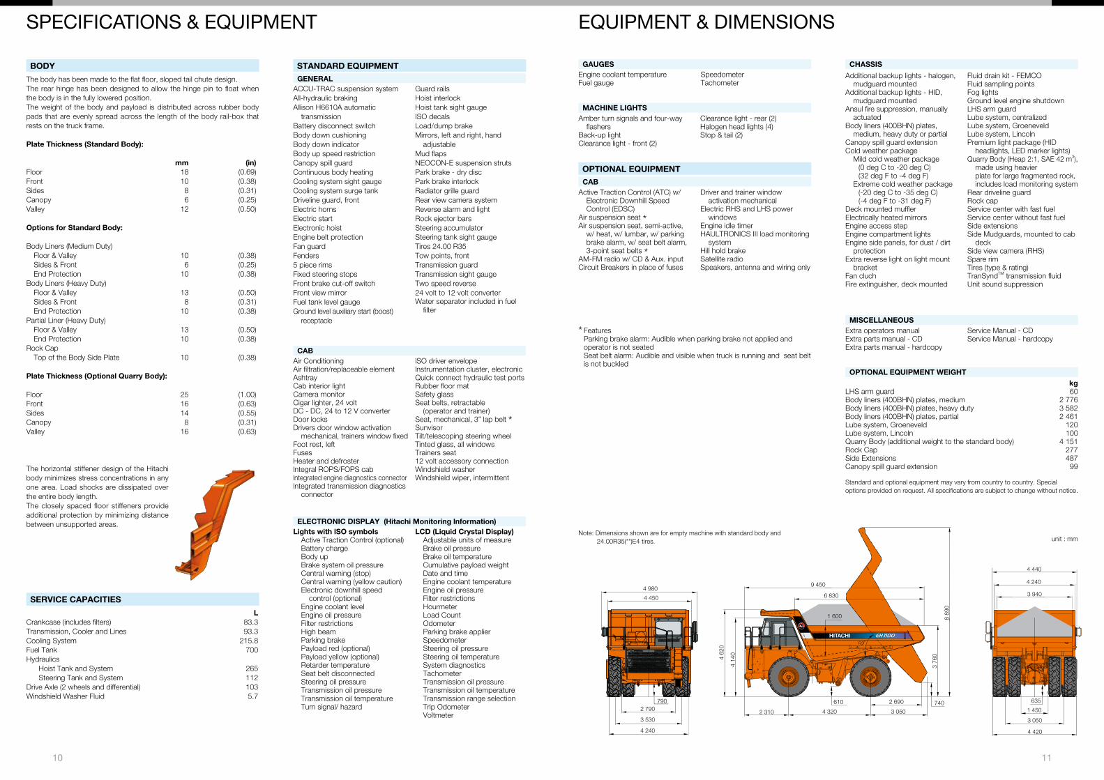
Note: Dimensions shown are for empty machine with standard body and 24�00R35(**)E4 tires�
KR-EN001R 10.0� (KA / KA, FT3)
Printed in Japan
Hitachi Construction Machinery Co., Ltd.www.hitachi-c-m.com
These specifications are subject to change without notice�Illustrations and photos show the standard models, and may or may not include optional equipment, accessories, and all standard equipment with some differences in color and features�Before use, read and understand the Operator’s Manual for proper operation�