15
• • •

Durham Research Online
Deposited in DRO:
15 April 2016
Version of attached �le:
Published Version
Peer-review status of attached �le:
Peer-reviewed
Citation for published item:
Chambers, P. and Augarde, C.E. and Reed, S. and Dobbins, A. (2016) 'Temporary propping at CrossrailPaddington station.', Geotechnical research., 3 (1). pp. 3-16.
Further information on publisher's website:
http://dx.doi.org/10.1680/jgere.15.00009
Publisher's copyright statement:
This is an open-access article distributed under the terms of the Creative Commons Attribution License, which permits
unrestricted use, distribution, and reproduction in any medium, provided the original work is properly cited.
Additional information:
Use policy
The full-text may be used and/or reproduced, and given to third parties in any format or medium, without prior permission or charge, forpersonal research or study, educational, or not-for-pro�t purposes provided that:
• a full bibliographic reference is made to the original source
• a link is made to the metadata record in DRO
• the full-text is not changed in any way
The full-text must not be sold in any format or medium without the formal permission of the copyright holders.
Please consult the full DRO policy for further details.
Durham University Library, Stockton Road, Durham DH1 3LY, United KingdomTel : +44 (0)191 334 3042 | Fax : +44 (0)191 334 2971
http://dro.dur.ac.uk
Temporary propping atCrossrail Paddington stationPaul Chambers MEngGraduate Engineer, Skanska UK, Rickmansworth, UK (correspondingauthor: [email protected])
Charles Augarde BSc, MSc, DPhil, CEng, FICEProfessor, School of Engineering and Computing Sciences, DurhamUniversity, Durham, UK
Sam Reed MEng, CEng, MICEConstruction Manager, Skanska UK, Rickmansworth, UK
Adrian Dobbins BSc, CEng, MICEEngineering Manager, Skanska UK, Rickmansworth, UK
The construction of Crossrail Paddington station in London (between 2011 and 2018) required a large temporary
propping system, which contained one of the most comprehensive monitoring schemes to date. This paper explores
the design and operation of this system through the analysis of a data set collected during the construction period
and the numerical modelling undertaken at Durham University. The effects of temperature variation on the partially
exposed propping system are quantified, as well as the impact of events in the construction sequence including slab
casting, adjacent prop removal and excavation. Several lessons were learned during the construction, in terms of
prop installation and removal and the management of the monitoring system. These are discussed for the benefit
of future projects using temporary propping and monitoring schemes. The findings from this research have led to a
greater understanding of the behaviour of propping systems under different environmental conditions, and may
therefore lead to more efficient and safer designs in the future.
NotationA cross-sectional area of the propE Young’s modulus of the prop materialE50 secant stiffnessEoed odeometer stiffnessEur un-/reloading stiffnessG0 reference shear modulusIp plasticity indexK0nc normally consolidated in situ earth pressurePref reference pressurep0o confining pressureROC overconsolidation ratioSu shear strengthSuinc incremental shear strengthSuref shear strength referencea thermal coefficient of the prop materialb system stiffnessg unit weightg0·7 shear strain at 0·7G0
DP change in thermal loaddT change in temperaturenur un-/reloading loading Poisson’s ratio
IntroductionCrossrail is a £14·8 billion underground rail project running fromReading and Heathrow to the west of London to Shenfield andAbbey Wood to the east. Ten new stations are being constructedas part of the project, of which the station at Paddington is uniquein terms of construction method. The station is constructed insidea single ‘box’ bounded by 1 m thick diaphragm walls, the
construction of which was completed in 2014. The box is 260 mlong, 25 m wide and 23 m deep and was built using a top-downmethod with temporary shoring and permanent slabs providingpropping to the walls. The site is located close to several surfacestructures, including the Grade 1-listed MacMillan House and the16-storey 20 Eastbourne Terrace. As a result, deformation controlduring construction was of extreme importance to the client. Tothis end, the principal contractor (Costain–Skanska Joint Venture(CJSV)) employed a rigorous monitoring system from which avaluable set of data was obtained.
It is widely accepted that greater understanding of the underlyingbehaviour of propping systems for large excavations, and theirresponse to variables such as temperature and constructionsequence, is needed to permit more economic designs. It mayalso lead to contractors being able to work in a safer and moreefficient manner. Poor understanding of temporary works for largeexcavations can have catastrophic results. In 2012 the New CivilEngineer magazine considered the Nicoll Highway collapse inSingapore to be the ‘greatest civil engineering disaster of the lastdecade’ (Hansford, 2012), highlighting some of the failings of thisproject as the incorrect choice and use of soil constitutive modelsin finite-element analyses (FEAs), the poor design of connectionsin the propping system and the omission of some structuralelements of temporary works (Browning, 2012).
To develop improved designs for propping schemes for largeexcavations, there must be a culture of evaluating the present stateof affairs and sharing experience gained from existing projects,both successful and unsuccessful. This is part of the philosophy
3
Geotechnical ResearchVolume 3 Issue 1
Temporary propping at CrossrailPaddington stationChambers, Augarde, Reed and Dobbins
Geotechnical Research, 2016, 3(1), 3–16http://dx.doi.org/10.1680/jgere.15.00009Paper 15.00009Received 05/11/2015; accepted 27/01/2016Published online 04/03/2016Keywords: diaphragm & in situ walls/ground improvement/temporary works
Published with permission by the ICE under the CC-BY license.(http://creativecommons.org/licenses/by/4.0/)
Downloaded by [ UNIVERSITY OF DURHAM] on [15/04/16]. Copyright © ICE Publishing, all rights reserved.
behind the Construction Industry Research and InformationAssociation (Ciria) design guide Ciria C580, Embedded RetainingWalls – Guidance for Economic Design (Gaba et al., 2003). Aconsultation workshop for the review of C580 in May 2014 foundthat many industry professionals would like to see more casestudies that compare design predictions with measurements duringthe construction phase (Ciria, 2014). The contractor at Paddingtonhad considerable experience with the propping of deep excavationsfrom projects such as the Channel Tunnel rail link (CTRL) andthe Crossrail Royal Oak portal, and wished to consolidate thisknowledge base along with that gained at Paddington for futurecontracts.
The works at Paddington involved one of the largest temporarypropping schemes of recent years, and the monitoring systememployed during the works appears to have been morecomprehensive than any to date. The aim of this paper is topresent selected conclusions drawn from the analysis of a largedata set obtained from this monitoring campaign and thenumerical modelling undertaken at Durham University during thefinal year of author Paul Chambers’ MEng studies. Four areasare focused on: (a) the effects of temperature variation on thepropping system, (b) the variation in prop loads with events inthe construction process and their sequence, (c) the effect ofprestressing the props and (d) the behaviour of the props in thecorner of the excavation. With upcoming projects such as HighSpeed 2 and Thames Tideway using the technology consideredin this research, the update of C580 becomes quite timely(Ciria, 2014), as does the presentation of recent findings frommonitoring data.
Previous research in open excavationmonitoringThere are several previous studies of large propped excavations inthe UK (mainly London), in which it is clear from the monitoringdata that a degree of overconservatism exists in design procedures.Loveridge (2001) used vibrating wire strain gauges andthermistors to analyse the effect of temperature variation on anexposed propping system monitored as part of the CTRL worksand found that the prop loads with ‘moderately conservative’design were up to twice the corresponding measured loads, afinding independent of the number of props and dewateringschemes. This indicated significant inefficiencies and a lackof understanding of the soil–structure interaction. In 2012, aninvestigation into the propping system at the Crossrail Royal Oakportal analysed load data from nine props (Ivanova, 2012). Thiswork found that thermal effects accounted for up to 30% of theload measured. Some attempts were also made to quantify theeffects of the casting of the base slab on the prop loadings, and,again, the loads measured on site were well below those expectedfrom the design. This was largely attributed to an overestimationof thermal loads.
These previous studies indicate that design assessments of theeffects of temperature, system restraint and construction sequence
on propped deep excavations could be overconservative, a findingthat is backed up by the data obtained at Paddington.
Considerable research into the physics that governs the behaviourof propped retaining walls has been undertaken over the last halfcentury. In the 2001 Perspective Lecture for the InternationalConference on Soil Mechanics and Geotechnical Engineering(Simpson and Powrie, 2001), the authors expressed some concernat the ‘considerable assumptions’ required for two-dimensional(2D) FEA. They also noted that there is still a ‘considerabledebate’ over how earth pressures are distributed. They state thatthe installation of a retaining wall might cause a drop in thelateral earth pressure coefficient of 10–20%. It is this lateral earthpressure that has the dominant effect on the geotechnical load inpropping systems. Furthermore, the authors state that prestressingprops or anchors can lead to higher wall bending moments. Thisimplies that there is an optimum level of prestressing, beyondwhich it is detrimental to the overall system. In an earlier work,Fourie and Potts (1985) found that prop forces will increase withboth the in situ lateral earth pressure coefficient K0 and the wallstiffness. Simic and French (1998) observed that temporarypropping is costly in terms of both time and money and providesa risk to site operatives during installation and removal. It istherefore ‘considerably advantageous’ to minimise the number ofprops in a scheme.
Monitoring of construction schemes and existing structures hasprovided significant knowledge in this field of research. In astudy of three different basement excavations, Marchand (1997)suggests that predicting ground movements is difficult due tothe range of soil stiffnesses that can be encountered over arelatively small area. In the investigation of Stothard Place inLondon, it was found that surfaces not in direct sunlight werenear ambient air temperature, despite a peak prop surfacetemperature of 480°C. On a similar note, in the investigation oftemporary propping at Canada Water, Powrie and Batten (2000)reported that the lower level of props had a higher averagetemperature than the upper level, indicating some degree ofthermal damping. Marchand (1997) found that during the winterthe raked props in the corner of the excavation recorded noload, which was attributed as ‘probably due to corner effects’.Marchand (1997) also suggested that prestress ‘dominates’ propbehaviour because prestress does not permit the soil to displaceand mobilise its maximum support. This finding is echoed byStroud et al. (1994), who concluded that across all of the sitesinvestigated, prop loads were almost always lower than the designvalues. This is attributed to an underestimation of short-term soilstrength, inaccurate assessment of soil stiffness and assumptionsin numerical models.
The effect of temperature variation in a propping system is largelygoverned by the degree of restraint in the system. The degree ofrestraint is expressed as a percentage and quantifies the ability ofstructural members to expand as they get warmer. If the systemis totally free to expand, the degree of restraint will be 0%.
4
Geotechnical ResearchVolume 3 Issue 1
Temporary propping at CrossrailPaddington stationChambers, Augarde, Reed and Dobbins
Downloaded by [ UNIVERSITY OF DURHAM] on [15/04/16]. Copyright © ICE Publishing, all rights reserved.

However, if the system cannot expand at all, then it is 100%restrained. This level of restraint in a system is affected by thestiffness of the retained soil and the connections between theprop, the wall and the soil mass. Gaba et al. (2003) suggested avalue of 70% for a stiff wall in stiff soil and 50% for a stiff wallin weak soil. Richards et al. (2007) found that the degree ofrestraint varied between 34% and 47% in an investigation ofa car park construction in Mayfair, London. In a paper inGéotechnique, Powrie and Batten (2000) found that a value of50% would have been more appropriate for the construction ofthe Canada Water station. Skanska’s internal research on theRoyal Oak portal presented the same conclusion (Ivanova,2012). In the investigation of another Mayfair car park (Richardset al., 1999), it was found that prop loads in the corners of theexcavation were lower than those near the middle. This was againattributed to ‘corner effects’. It appears that the term ‘cornereffects’ has been used in a number of cases as a blanket term forlower than expected prop loads near the corners of an excavation.However, none of the papers reviewed as part of this project gointo any great detail as to what corner effects actually are.
Several papers present the results of investigations of retainingwalls and propping systems using numerical modelling. Powrieand Batten (2000) compared the measurements taken fromconstruction with those from a FEA using the software Crisp.The authors chose to use a linear elastic/perfectly plastic(Mohr–Coulomb) constitutive model for the soil. This does notmodel the inherent non-linearity of soil but was justified based onan earlier paper by Burland and Kalra (1986). The slab/wallinteractions were modelled as pinned joints, based on the earlierfindings of Powrie and Li (1991). Following a parametric study,the authors reported that soil stiffness has the largest effect on walldisplacements. Gourvenec et al. (2002) compared displacementsfound at a wall retained by a berm in two and three dimensions toexplore the effect of the assumption that a 2D section will providean accurate representation of the system. The paper states thathorizontal ground movement during wall installation is reduced by83% when modelling in three dimensions. In the paper of Powrieand Li (1991), the effect of varying soil, wall and prop stiffnesses,along with the pre-excavation earth pressure coefficient, wasexplored. The paper suggests that the bending moments in thewalls are mainly dominated by the in situ lateral earth pressure.Furthermore, it reports that small variations in stress distributionscan cause comparatively large changes in the prop load. A keytheme across all of the papers discussing numerical modelling thatwere reviewed as part of this project is the importance of statingclearly the assumptions used in an analysis.
Site conditions and monitoring at Paddington
Ground conditionsThe underlying geology at Paddington is typical of a centralLondon excavation. The site is partially underlain by Pleistoceneriver terrace deposits (Lynch Hill gravel), over Eocene LondonClay and Harwich formation underlain by the Lambeth Group,
Thanet sand formation and Cretaceous Upper Chalk (BGS, 1994).Figure 1 illustrates the typical soil stratigraphy across the site.
Although there are two known aquifers below the site, nogroundwater was recorded during the geotechnical investigationsprior to excavation. This is likely a result of London Clay’s lowpermeability. The site has a long history of rail-related industry,and, therefore, some contamination in the made ground and riverterrace deposits was expected; indeed, 5% of the made groundand 3% of the river terrace deposits excavated were classified ashazardous under waste acceptance criteria. As expected with sucha densely populated brownfield site, several services had to bediverted before excavation could begin.
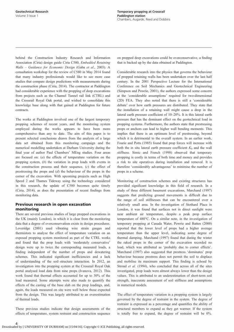
The propping systemFifty props were required for the construction of the box forCrossrail Paddington. The chosen props were sourced fromGroundforce Shorco and were thought at that time to be thelargest proprietary props available in the UK. Forty-two MP500props spanned the width of the excavation, while two MP250props were used in a raking configuration in each corner(Figure 2). All of the props were connected to 900 mm × 600 mmfabricated plate girder walers, which in turn were connected to the1 m thick diaphragm walls that bounded the construction. Theprops were designed for a factored ultimate limit state designgeotechnical load of 7790 kN and a temperature change of+30°C, creating a characteristic design load of 3203 kN. This
Madeground
River terracedeposits
LondonClay
GL
3·0 m
6·5 m
Lambeth group
59·1 m
~73·0 m
Figure 1. Ground profile at Crossrail Paddington
5
Geotechnical ResearchVolume 3 Issue 1
Temporary propping at CrossrailPaddington stationChambers, Augarde, Reed and Dobbins
Downloaded by [ UNIVERSITY OF DURHAM] on [15/04/16]. Copyright © ICE Publishing, all rights reserved.
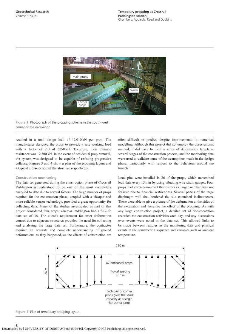
resulted in a total design load of 12 010 kN per prop. Themanufacturer designed the props to provide a safe working loadwith a factor of 2·0 of 6250 kN. Therefore, their ultimateresistance was 12 500 kN. In the event of accidental prop removal,the system was designed to be capable of resisting progressivecollapse. Figures 3 and 4 show a plan of the propping layout anda typical cross-section of the structure respectively.
Construction monitoringThe data set generated during the construction phase of CrossrailPaddington is understood to be one of the most completelyanalysed to date due to several factors. The large number of propsrequired for the construction phase, coupled with a cheaper andmore reliable sensor technology, provided a great opportunity forcollecting data. Many of the studies investigated as part of thisproject considered four props, whereas Paddington had a full-lifedata set of 36. The client’s requirement for strict deformationcontrol due to adjacent structures provided the need for collectingand analysing the large data set. Furthermore, the contractorrequired an accurate and complete understanding of grounddeformations as they happened, as the effects of construction are
often difficult to predict, despite improvements in numericalmodelling. Although this project did not employ the observationalmethod, it did have to meet a series of deformation targets atseveral stages of the construction process, and the monitoring datawere used to validate some of the assumptions made in the designphase, particularly with respect to the behaviour around thetunnels.
Load pins were installed in 36 of the props, which transmittedload data every 15 min by using vibrating wire strain gauges. Fourprops had surface-mounted thermistors (a larger number was notfeasible due to financial restrictions). Several panels of the largediaphragm wall that bordered the site contained inclinometers.These were able to give a picture of the deformation at the sides ofthe excavation and therefore the effect of the propping. As withany large construction project, a detailed set of documentationrecorded the construction activities each day, and any discussionsover events were noted in the data set. This allowed links tobe made between features in the monitoring data and physicalevents in the construction sequence and variables such as ambienttemperature.
Main props
Cornerprops
Waler
Figure 2. Photograph of the propping scheme in the south-westcorner of the excavation
250 m
42 horizontal props
Typical spacing6·11 m
Each pair of cornerprops gives the samecapacity as a single
horizontal prop
24 m
Figure 3. Plan of temporary propping layout
6
Geotechnical ResearchVolume 3 Issue 1
Temporary propping at CrossrailPaddington stationChambers, Augarde, Reed and Dobbins
Downloaded by [ UNIVERSITY OF DURHAM] on [15/04/16]. Copyright © ICE Publishing, all rights reserved.

The following steps illustrate the flow of load and temperaturedata from the props to the site team.
■ The prop load pin measures axial load every 15 min.■ The load pin wirelessly transmits data to two recording
stations situated at either end of the excavation.■ Recording stations transmit the load data to a remote server
using the 3G mobile network.
In most cases the time bases used in sampling at the tworecording stations were not consistent, which convenientlyallowed the data streams to be merged for a higher data densityover a given time period.
Before any conclusions could be drawn from the data, they had tobe validated. Plots of load against time were produced on a scattergraph for each recording station on all of the props. This allowedcomparison between the props and made it easier to identifyanomalies visually. A number of errors were found and theseare detailed in Table 1 along with the event that is understood tohave caused them. The sources for these errors were foundthrough meetings with the CSJV site team and consultation withGroundforce Shorco.
Temperature effects
Temperature variation in a partially exposed excavationAlthough there is guidance on considering temperature effectson exposed structures, such as bridge decks, few studies haveexplored the response of partially covered temporary propping toambient temperature changes. Due to its top-down constructionmethod, most of Paddington’s propping system was covered bya partially complete roof slab (with access holes to the worksbelow) and the tall structures on the site’s boundary providedadditional shade. Temperature on site was measured in three ways
■ steel surface temperature thermistors on four of the props■ ambient air temperature taken from the two recording stations
below the roof
Top of D-wall
Roof slab
Intermediate slab
Temporary props
Concourse slab
Base slab
Trainlevel
D-Wall toe 85·500
102·560
104·310
111·430
112·850
114·500
117·050
118·050
122·175
123·175124·000
Figure 4. Section through structure including temporary propping.All levels are given in metres above tunnel datum
Error Cause
Short gap in data stream for station A Tracked vehicle damaged data cable for receiver stationShort gap in data stream for both stations in January Vodafone updated mobile network mast to 4GClipping of load data at 600 t Failure of vibrating wire strain gauge7 d gaps in data for each site at different times Recording station battery failure at both sites (not concurrent)Inconsistencies in CSV data sheet Technician reassigned channel numbers on one station,
possibly affecting data on the datum websiteOne recording station lagging the other by8 d 20min
Technician rebooted site A with site B start-up file after battery failure
Table 1. Errors and causes in load monitoring
7
Geotechnical ResearchVolume 3 Issue 1
Temporary propping at CrossrailPaddington stationChambers, Augarde, Reed and Dobbins
Downloaded by [ UNIVERSITY OF DURHAM] on [15/04/16]. Copyright © ICE Publishing, all rights reserved.
■ external ambient temperature taken from total stationsmounted on external buildings.
The readings from the total stations were collated for the nearestthree to the works over the period from November 2013 toAugust 2014. Once plotted, it was clear that there was a goodcorrelation between the total stations, so their data were merged.This allowed comparisons of the temperature measured aboveground with the temperature measured below the roof slab and thesurface temperature of the props. This information is shown inTable 2.
The prop surface temperature follows the same trends as theinternal and external temperatures, but with a much smalleramplitude. As can be seen in Table 2, the prop experiences amuch smaller temperature variation during its lifespan (16°C)compared with the design value (30°C), suggesting thatthis parameter was overconservative for a partially coveredexcavation.
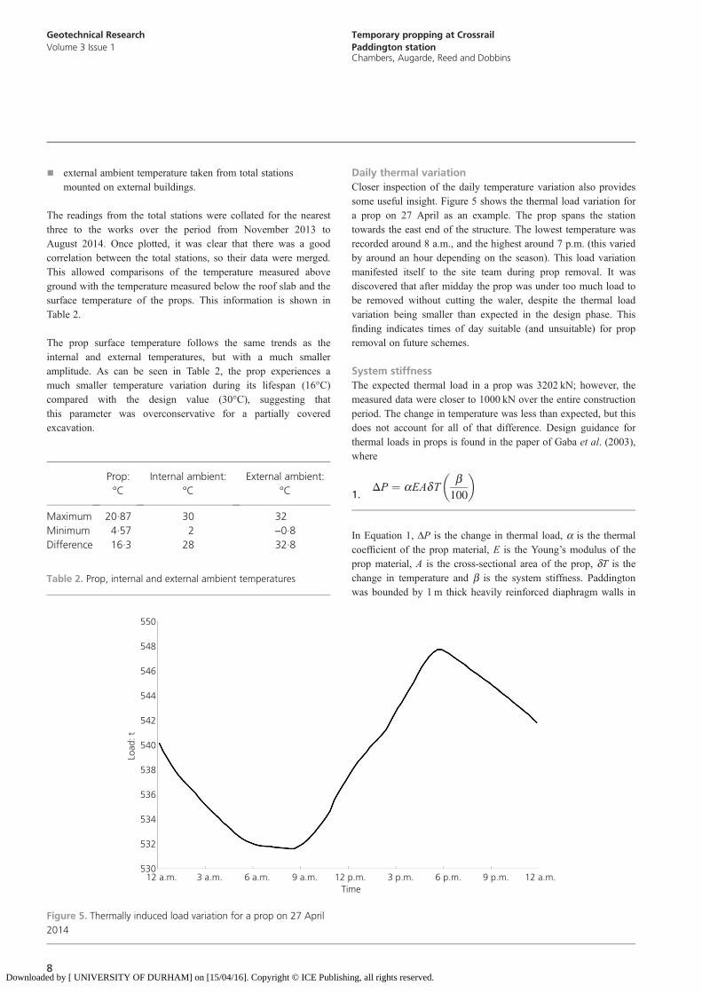
Daily thermal variationCloser inspection of the daily temperature variation also providessome useful insight. Figure 5 shows the thermal load variation fora prop on 27 April as an example. The prop spans the stationtowards the east end of the structure. The lowest temperature wasrecorded around 8 a.m., and the highest around 7 p.m. (this variedby around an hour depending on the season). This load variationmanifested itself to the site team during prop removal. It wasdiscovered that after midday the prop was under too much load tobe removed without cutting the waler, despite the thermal loadvariation being smaller than expected in the design phase. Thisfinding indicates times of day suitable (and unsuitable) for propremoval on future schemes.
System stiffnessThe expected thermal load in a prop was 3202 kN; however, themeasured data were closer to 1000 kN over the entire constructionperiod. The change in temperature was less than expected, but thisdoes not account for all of that difference. Design guidance forthermal loads in props is found in the paper of Gaba et al. (2003),where
ΔP ¼ aEAdTb100
� �1.
In Equation 1, DP is the change in thermal load, a is the thermalcoefficient of the prop material, E is the Young’s modulus of theprop material, A is the cross-sectional area of the prop, dT is thechange in temperature and b is the system stiffness. Paddingtonwas bounded by 1 m thick heavily reinforced diaphragm walls in
Prop:°C
Internal ambient:°C
External ambient:°C
Maximum 20·87 30 32Minimum 4·57 2 −0·8Difference 16·3 28 32·8
Table 2. Prop, internal and external ambient temperatures
530
532
534
536
538
540
542
544
546
548
550
12 a.m. 3 a.m. 6 a.m. 9 a.m. 12 p.m. 3 p.m. 6 p.m. 9 p.m. 12 a.m.
Load
: t
Time
Figure 5. Thermally induced load variation for a prop on 27 April2014
8
Geotechnical ResearchVolume 3 Issue 1
Temporary propping at CrossrailPaddington stationChambers, Augarde, Reed and Dobbins
Downloaded by [ UNIVERSITY OF DURHAM] on [15/04/16]. Copyright © ICE Publishing, all rights reserved.
stiff London Clay, and so a value of b = 70 was chosen duringthe design. dT was specified by the designer as +30°C. Thematerial parameters for steel are well understood and have littlevariation, so it was decided that the system stiffness, or the degreeof restraint, warranted further investigation.
The thermally induced loads and the surface temperatures wereused to back-analyse the system stiffness for all of the props withsurface temperature monitoring. Thirty-six daily cycles weresampled. The results of this are shown in Table 3. These resultsare similar to those presented in a study conducted at CrossrailRoyal Oak portal (Ivanova, 2012) and suggest that the b value forstiff walls in stiff clay is better set to 50 rather than 70.
The overall effect of the combination of a lower than expectedsystem stiffness and a lower temperature variation is considerable.The design thermal load was 3202 kN, and the largest thermalload using the maximum observed system stiffness andtemperature variation was 1136 kN – that is, 35% of the expectedvalue. The largest daily variation was 167 kN. Based on currentlyaccepted procedures used in the industry, it appears that there ispotential for considerable economy in propping works of thisnature.
Construction sequenceA better understanding of the effects of different events in theconstruction process can not only highlight potential economies tobe gained but also lead to the design of safer systems. The prop loaddata at Paddington were compared with information from the sitediaries to explore the effect of different items of construction work.
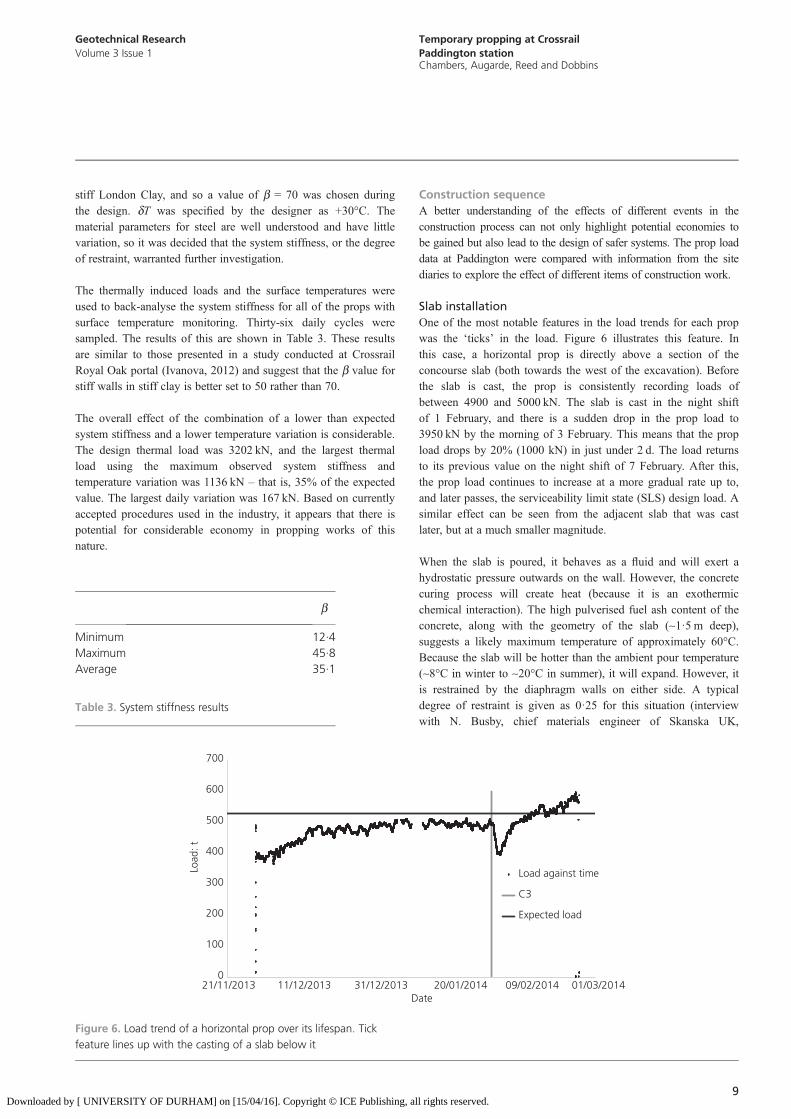
Slab installationOne of the most notable features in the load trends for each propwas the ‘ticks’ in the load. Figure 6 illustrates this feature. Inthis case, a horizontal prop is directly above a section of theconcourse slab (both towards the west of the excavation). Beforethe slab is cast, the prop is consistently recording loads ofbetween 4900 and 5000 kN. The slab is cast in the night shiftof 1 February, and there is a sudden drop in the prop load to3950 kN by the morning of 3 February. This means that the propload drops by 20% (1000 kN) in just under 2 d. The load returnsto its previous value on the night shift of 7 February. After this,the prop load continues to increase at a more gradual rate up to,and later passes, the serviceability limit state (SLS) design load. Asimilar effect can be seen from the adjacent slab that was castlater, but at a much smaller magnitude.
When the slab is poured, it behaves as a fluid and will exert ahydrostatic pressure outwards on the wall. However, the concretecuring process will create heat (because it is an exothermicchemical interaction). The high pulverised fuel ash content of theconcrete, along with the geometry of the slab (~1·5 m deep),suggests a likely maximum temperature of approximately 60°C.Because the slab will be hotter than the ambient pour temperature(~8°C in winter to ~20°C in summer), it will expand. However, itis restrained by the diaphragm walls on either side. A typicaldegree of restraint is given as 0·25 for this situation (interviewwith N. Busby, chief materials engineer of Skanska UK,
b
Minimum 12·4Maximum 45·8Average 35·1
Table 3. System stiffness results
0
100
200
300
400
500
600
700
21/11/2013 11/12/2013 31/12/2013 20/01/2014 09/02/2014 01/03/2014
Load
: t
Date
Load against time
C3
Expected load
Figure 6. Load trend of a horizontal prop over its lifespan. Tickfeature lines up with the casting of a slab below it
9
Geotechnical ResearchVolume 3 Issue 1
Temporary propping at CrossrailPaddington stationChambers, Augarde, Reed and Dobbins
Downloaded by [ UNIVERSITY OF DURHAM] on [15/04/16]. Copyright © ICE Publishing, all rights reserved.

28 August 2014). It is hypothesised that as the slab expands, itpushes the diaphragm walls out of the excavation and, thus,relieves load from the props. As the slab cures further, it willcontract and pull the diaphragm walls back into the excavation,increasing the prop loads to their earlier level or more. In manycases this behaviour appears to have loaded a prop over its SLSload value. Strain gauges and thermistors in the slab would permitfurther investigation of this behaviour.
Prop removalRemoving adjacent props caused a load redistribution in thepropping system. However, as a slab had been cast and curedbelow the props, it is likely that the majority of the load they werecarrying was transferred to the slab below them. This resulted in asmall change in prop load compared with the total load. Therefore,in the case of Paddington, removing adjacent props did not haveany great impact on the prop loads or the construction process.
ExcavationAfter a prop was installed on a day shift, excavation proceededtowards the south-east in the night shift. This excavation loweredthe passive earth resistance in front of the wall and therefore isexpected to have increased the prop load. It is possible that thisis represented by the rate of prop load increase, illustrated inFigure 7. The overlain curve shows how the rate of load increasevaries with time. The rate of load gain decreases as the excavationprogresses. This trend was not significant in all props.
Prestressing the props
Establishing the modelAll of the props used in the construction of Paddington werepreloaded to 70% of their design value. This meant that the load
data could not show how deflections varied with prestress. Anumerical model was required in order to do a parametric studyof the effect of varying prestress. It was decided that a 2D planestrain analysis would be suitable for this task, in part due to thelinear nature of the site and also due to software availability. Boththe finite-element software Plaxis and the spring stiffness softwareWallap were used by the designers (Scott Wilson). However, theoptions for soil models and the availability of support at Durhammade Plaxis more suitable for this study. The model was based ona section through the excavation that had reliable results for loadand deflections from inclinometers installed in the diaphragmwall. Once the deflected profile of the model matched the profilemeasured by the inclinometer, an analysis of the sensitivity ofdifferent parameters was undertaken. The results of this werethen compared with those of previous studies. When the modelmimicked the results measured on site, the prop preload could bevaried to see its impact on wall deflections. Unfortunately, due totime constraints, this experiment was conducted on only onesection of the works. The data for future evaluation of sections arein existence and controlled by the principal contractor for theworks.
An important consideration is the choice of soil constitutivemodel. Plaxis provides a number of in-built models as well as theoption of creating a user-defined model. It was decided thatdeveloping a user-defined model was beyond the scope of thisproject (again due to time limitations). Previous studies on thesuitability of material models in Plaxis 2D to different purposesindicated that the hardening soil (HS) model is appropriate forexcavations (Xu and Wang, 2010). The HS model simulates non-linear soil behaviour with shear hardening (Schanz et al., 1999).With a small modification, the hardening soil model becomes theHS small model, which also considers the small elastic region for
350
400
450
500
550
600
650
700
750
800
02/11/2013 22/11/2013 12/12/2013 01/01/2014 21/01/2014 10/02/2014 02/03/2014
Load
: t
Time
Figure 7. The rate of load gain decreases after the beginning ofthe prop’s lifespan due to excavation, becoming steady until a slabis cast below it
10
Geotechnical ResearchVolume 3 Issue 1
Temporary propping at CrossrailPaddington stationChambers, Augarde, Reed and Dobbins
Downloaded by [ UNIVERSITY OF DURHAM] on [15/04/16]. Copyright © ICE Publishing, all rights reserved.
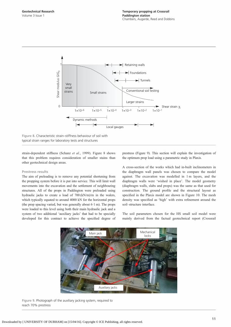
strain-dependent stiffness (Schanz et al., 1999). Figure 8 showsthat this problem requires consideration of smaller stains thanother geotechnical design areas.
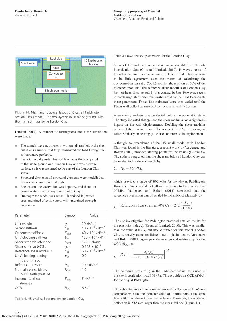
Prestress resultsThe aim of preloading is to remove any potential shortening fromthe propping system before it is put into service. This will limit wallmovements into the excavation and the settlement of neighbouringstructures. All of the props in Paddington were preloaded usinghydraulic jacks to create a load of 700 (kN/m)/m in the walers,which typically equated to around 4000 kN for the horizontal props(the prop spacing varied, but was generally about 6·1 m). The propswere loaded to this level using both their main hydraulic jack and asystem of two additional ‘auxiliary jacks’ that had to be speciallydeveloped for this contract to achieve the specified degree of
prestress (Figure 9). This section will explain the investigation ofthe optimum prop load using a parametric study in Plaxis.
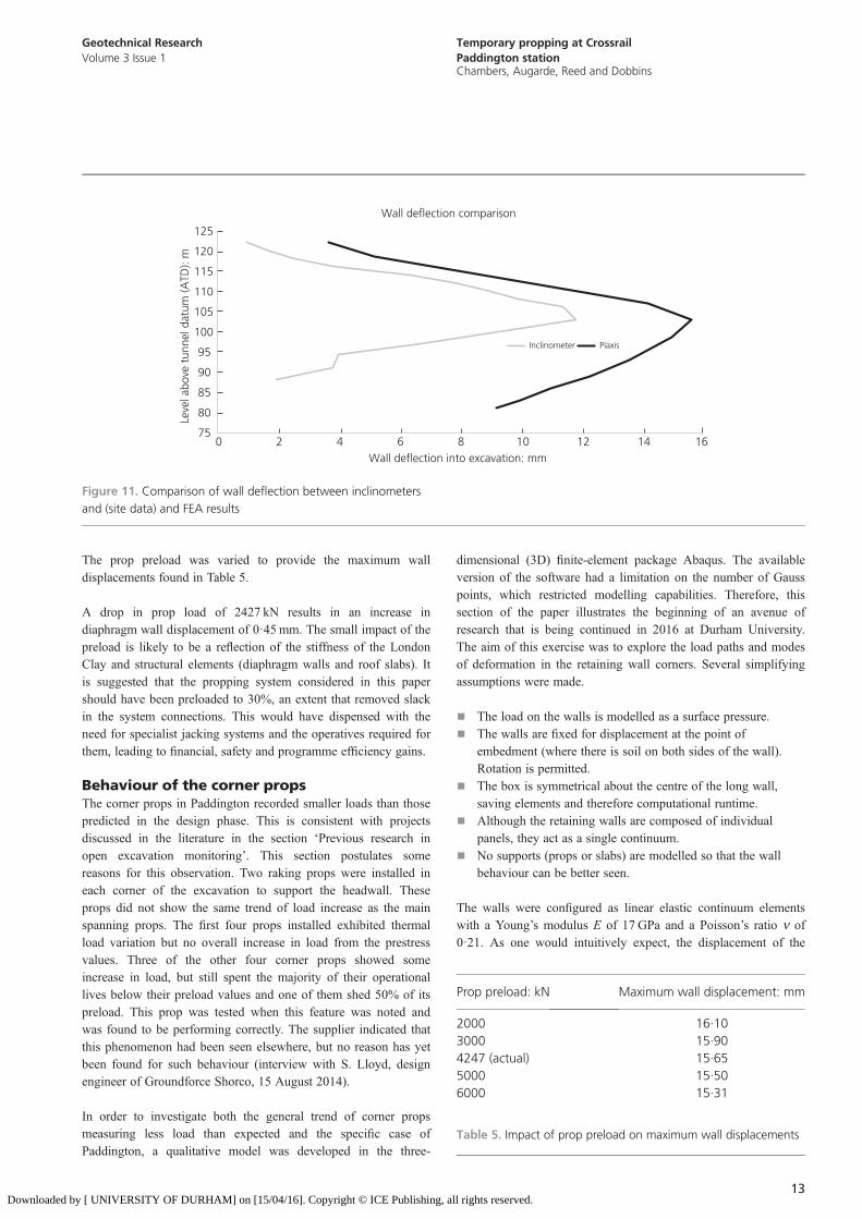
A cross-section of the works which had in-built inclinometers inthe diaphragm wall panels was chosen to compare the modelagainst. The excavation was modelled in 1 m layers, and thediaphragm walls were ‘wished in place’. The model geometry(diaphragm walls, slabs and props) was the same as that used forconstruction. The ground profile and the structural layout asspecified in the Plaxis model are shown in Figure 10. The meshdensity was specified as ‘high’ with extra refinement around thesoil–structure interface.
The soil parameters chosen for the HS small soil model weremainly derived from the factual geotechnical report (Crossrail
Retaining walls
Foundations
Tunnels
Conventional soil testing
Larger strains
Small strains
Shear strain γs
Dynamic methods
Local gauges
1×10⁻⁶ 1×10⁻⁵ 1×10⁻⁴ 1×10⁻³ 1×10⁻² 1×10⁻¹
Verysmallstrains
1
0
Shea
r m
odul
us G
/G0
Figure 8. Characteristic strain–stiffness behaviour of soil withtypical strain ranges for laboratory tests and structures
Main jack Mechanicallocks
Auxiliary jacks
Figure 9. Photograph of the auxiliary jacking system, required toreach 70% prestress
11
Geotechnical ResearchVolume 3 Issue 1
Temporary propping at CrossrailPaddington stationChambers, Augarde, Reed and Dobbins
Downloaded by [ UNIVERSITY OF DURHAM] on [15/04/16]. Copyright © ICE Publishing, all rights reserved.
Limited, 2010). A number of assumptions about the simulationwere made.
■ The tunnels were not present: two tunnels ran below the site,but it was assumed that they transmitted the load through thesoil structure perfectly.
■ River terrace deposits: this soil layer was thin comparedto the made ground and London Clay and was near thesurface, so it was assumed to be part of the London Claystrata.
■ Structural elements: all structural elements were modelled aslinear elastic isotropic materials.
■ Excavation: the excavation was kept dry, and there is nogroundwater flow through the London Clay.
■ Drainage: the model was set as ‘Undrained B’, whichuses undrained effective stress with undrained strengthparameters.
Table 4 shows the soil parameters for the London Clay.
Some of the soil parameters were taken straight from the siteinvestigation data (Crossrail Limited, 2010). However, some ofthe other material parameters were trickier to find. There appearsto be little agreement over the means of calculating theoverconsolidation ratio (OCR) and the shear strain at 70% of thereference modulus. The reference shear modulus of London Clayhas not been documented in this context before. However, recentresearch suggested some relationships that can be used to calculatethese parameters. These ‘first estimates’ were then varied until thePlaxis wall deflection matched the measured wall deflection.
A sensitivity analysis was conducted before the parametric study.The study indicated that g0·7 and the shear modulus had a significantimpact on the wall displacements. Doubling the shear modulusdecreased the maximum wall displacement to 75% of its originalvalue. Similarly, increasing g0·7 caused an increase in displacement.
Although no precedence of the HS small model with LondonClay was found in the literature, a recent work by Vardenega andBolton (2011) provided starting points for the values g0·7 and G0.The authors suggested that the shear modulus of London Clay canbe related to the shear strength by
G0 ¼ 320 �7Su2.
which provides a value of 39·3MPa for the clay at Paddington.However, Plaxis would not allow this value to be smaller than50MPa. Vardenega and Bolton (2013) suggested that thereference shear strain can be related to the index of plasticity by
Reference shear strain at 50%G0 ¼ 2 �2 Ip1000
� �3.
The site investigation for Paddington provided detailed results forthe plasticity index Ip (Crossrail Limited, 2010). This was smallerthan the value at 0·7G0 but should suffice for this model. LondonClay is heavily overconsolidated due to glacial action. Vardenegaand Bolton (2013) again provide an empirical relationship for theOCR (ROC) as
ROC ¼ su=p0o0 �11þ 0 �0037 ðIpÞ
� �1�254.
The confining pressure p0o in the undrained triaxial tests used inthe site investigation was 100 kPa. This provides an OCR of 6·54for the clay at Paddington.
The calibrated model had a maximum wall deflection of 15·65 mmcompared with the inclinometer value of 13 mm, both at the samelevel (103·5m above tunnel datum level). Therefore, the modelleddeflection is 2·65 mm larger than the measured one (Figure 11).
Mac House
Roof slab40 Eastbourne
TerraceProp
Concourseslab
Diaphragm walls
Figure 10. Mesh and structural layout of Crossrail Paddingtonsection (Plaxis model). The top layer of soil is made ground, withthe main soil mass being London Clay
Parameter Symbol Value
Unit weight g 20 kN/m3
Secant stiffness E50 40 × 103 kN/m2
Odeometer stiffness Eoed 40 × 103 kN/m2
Un-/reloading stiffness Eur 120 × 103 kN/m2
Shear strength reference Suref 122·5 kN/m2
Shear strain at 0·7G0 g0·7 0·968 × 10−3
Reference shear modulus G0 50 × 103 kN/m2
Un-/reloading loadingPoisson’s ratio
nur 0·2
Reference pressure Pref 100 kN/m2
Normally consolidatedin-situ earth pressure
K0nc 1·0
Incremental shearstrength
Suinc 5 kN/m2
OCR ROC 6·54
Table 4. HS small soil parameters for London Clay
12
Geotechnical ResearchVolume 3 Issue 1
Temporary propping at CrossrailPaddington stationChambers, Augarde, Reed and Dobbins
Downloaded by [ UNIVERSITY OF DURHAM] on [15/04/16]. Copyright © ICE Publishing, all rights reserved.
The prop preload was varied to provide the maximum walldisplacements found in Table 5.
A drop in prop load of 2427 kN results in an increase indiaphragm wall displacement of 0·45 mm. The small impact of thepreload is likely to be a reflection of the stiffness of the LondonClay and structural elements (diaphragm walls and roof slabs). Itis suggested that the propping system considered in this papershould have been preloaded to 30%, an extent that removed slackin the system connections. This would have dispensed with theneed for specialist jacking systems and the operatives required forthem, leading to financial, safety and programme efficiency gains.
Behaviour of the corner propsThe corner props in Paddington recorded smaller loads than thosepredicted in the design phase. This is consistent with projectsdiscussed in the literature in the section ‘Previous research inopen excavation monitoring’. This section postulates somereasons for this observation. Two raking props were installed ineach corner of the excavation to support the headwall. Theseprops did not show the same trend of load increase as the mainspanning props. The first four props installed exhibited thermalload variation but no overall increase in load from the prestressvalues. Three of the other four corner props showed someincrease in load, but still spent the majority of their operationallives below their preload values and one of them shed 50% of itspreload. This prop was tested when this feature was noted andwas found to be performing correctly. The supplier indicated thatthis phenomenon had been seen elsewhere, but no reason has yetbeen found for such behaviour (interview with S. Lloyd, designengineer of Groundforce Shorco, 15 August 2014).
In order to investigate both the general trend of corner propsmeasuring less load than expected and the specific case ofPaddington, a qualitative model was developed in the three-
dimensional (3D) finite-element package Abaqus. The availableversion of the software had a limitation on the number of Gausspoints, which restricted modelling capabilities. Therefore, thissection of the paper illustrates the beginning of an avenue ofresearch that is being continued in 2016 at Durham University.The aim of this exercise was to explore the load paths and modesof deformation in the retaining wall corners. Several simplifyingassumptions were made.
■ The load on the walls is modelled as a surface pressure.■ The walls are fixed for displacement at the point of
embedment (where there is soil on both sides of the wall).Rotation is permitted.
■ The box is symmetrical about the centre of the long wall,saving elements and therefore computational runtime.
■ Although the retaining walls are composed of individualpanels, they act as a single continuum.
■ No supports (props or slabs) are modelled so that the wallbehaviour can be better seen.
The walls were configured as linear elastic continuum elementswith a Young’s modulus E of 17 GPa and a Poisson’s ratio n of0·21. As one would intuitively expect, the displacement of the
75
80
85
90
95
100
105
110
115
120
125
0 2 4 6 8 10 12 14 16
Leve
l abo
ve t
unne
l dat
um (A
TD):
m
Wall deflection into excavation: mm
Wall deflection comparison
Inclinometer Plaxis
Figure 11. Comparison of wall deflection between inclinometersand (site data) and FEA results
Prop preload: kN Maximum wall displacement: mm
2000 16·103000 15·904247 (actual) 15·655000 15·506000 15·31
Table 5. Impact of prop preload on maximum wall displacements
13
Geotechnical ResearchVolume 3 Issue 1
Temporary propping at CrossrailPaddington stationChambers, Augarde, Reed and Dobbins
Downloaded by [ UNIVERSITY OF DURHAM] on [15/04/16]. Copyright © ICE Publishing, all rights reserved.
long wall sections was significantly greater than that of theheadwalls. One method of exploring the 3D behaviour of the wallis to assign the corners of the box different values of stiffness.This artificially separates the walls, which is how the system isdesigned in industry (Figure 12). Table 6 shows the impact ofassuming that the walls act independently. Positive displacementsare into the excavation.
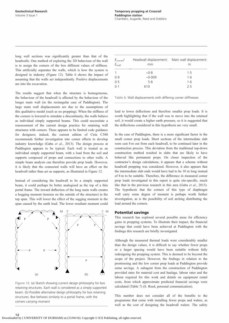
The results suggest that when the structure is homogeneous,the behaviour of the headwall is affected by the behaviour of thelonger main wall (in the rectangular case of Paddington). Thelarge main wall displacements are due to the assumptions ofthis qualitative model (such as no propping). When the stiffness ofthe corners is lowered to simulate a discontinuity, the walls behaveas individual simply supported beams. This could necessitate areassessment of the current design practice for retaining wallstructures with corners. There appears to be limited code guidancefor designers; indeed, the current edition of Ciria C580recommends further investigation into corner effects to developindustry knowledge (Gaba et al., 2013). The design process atPaddington appears to be typical. Each wall is treated as anindividual simply supported beam, with a load from the soil andsupports composed of props and connections to other walls. Asimple beam analysis can therefore provide prop loads. However,it is likely that the connected walls will have an effect on theheadwall rather than act as supports, as illustrated in Figure 12.
Instead of considering the headwall to be a simply supportedbeam, it could perhaps be better analogised as the top of a thinportal frame. The inward deflection of the long main walls createsa hogging moment (tension on the outside of the structure) in thetop span. This will lower the effect of the sagging moment in thespan caused by the earth load. The lower resultant moment could
lead to lower deflections and therefore smaller prop loads. It isworth highlighting that if the wall was to move into the retainedsoil, it would create a higher earth pressure, so it is suggested thatthe deflections considered in this hypothesis are very small.
In the case of Paddington, there is a more significant factor in thesmall corner prop loads. Short sections of the intermediate slabwere cast 8 m out from each headwall, to be continued later in theconstruction process. This deviation from the traditional top-downconstruction method resulted in slabs that are likely to havebehaved like permanent props. On closer inspection of thecontractor’s design calculations, it appears that a scheme withoutheadwall propping was considered. However, it also appears thatthe intermediate slab ends would have had to be 10 m long insteadof 8 m to be suitable. Therefore, the difference in measured cornerprop loads investigated in this report is quite site-specific, muchlike that in the previous research in this area (Gaba et al., 2013).The hypothesis that the corners of this type of diaphragmwall carry some degree of moment is perhaps worth furtherinvestigation, as is the possibility of soil arching distributing theload around the corners.
Potential savingsThis research has explored several possible areas for efficiencygains in propping systems. To illustrate their impact, the financialsavings that could have been achieved at Paddington with thefindings this research are briefly investigated.
Although the measured thermal loads were considerably smallerthan the design values, it is difficult to say whether fewer propsor a larger spacing would have been suitable without fullyredesigning the propping system. This is deemed to be beyond thescope of the project. However, the findings in relation to theprestressing and the low corner prop loads at Paddington providesome savings. A subagent from the construction of Paddingtonprovided rates for material cost and haulage, labour rates and thelabour required for this work and details on equipment rentalcosts, from which approximate predicted financial savings werecalculated (Table 7) (S. Reed, personal communication).
This number does not consider all of the benefits to theprogramme that come with installing fewer props and walers, aswell as the cost of designing the headwall walers. The safety
P
P P
P
(a)
M M
P P
P
(b)
Figure 12. (a) Sketch showing current design philosophy for boxretaining structures. Each wall is considered as a simply supportedbeam. (b) Possible alternative design philosophy for box retainingstructures. Box behaves similarly to a portal frame, with thecorners carrying moment
Ecorner/Ewall
Headwall displacement:mm
Main wall displacement:m
1 −0·8 1·50·9 −0·009 1·60·5 5·8 1·60·1 610 2·5
Table 6. Wall displacements with differing corner stiffnesses
14
Geotechnical ResearchVolume 3 Issue 1
Temporary propping at CrossrailPaddington stationChambers, Augarde, Reed and Dobbins
Downloaded by [ UNIVERSITY OF DURHAM] on [15/04/16]. Copyright © ICE Publishing, all rights reserved.
benefits of installing fewer props cannot be quantified. However,considering these possible savings alone account for around 15%of total cost for the propping system.
Although approximate, these results indicate that there aresignificant economies to be made in the design of proppingsystems.
ConclusionsThis paper records the investigation and analysis of the temporarypropping system used in the construction of Crossrail Paddingtonstation while also considering the wider industry design oftemporary propping systems. The measured temperature variation onthe prop surfaces was approximately half of that specified at thedesign stage, indicating considerable thermal damping in partiallyexposed systems. The stiffness of the propping system was back-calculated and compared with the design value. It was found that thesystem stiffness averaged 35%, compared to the 70% recommendedin the design guide, Ciria C580. The combination of these factorsresulted in a maximum measured thermal load of approximately1000 kN, compared with a design thermal load of 3202 kN.
A parametric study using the finite-element software Plaxis wasundertaken to explore the impact of different levels of prestress in thepropping system. While the system at Paddington was prestressed to70% of its SLS design value, the results of the study indicate thatthis was not necessary. A preload of 30% resulted in wall deflectionswell within the trigger values. Therefore, the additional jackingsystem that had to be developed for the 70% preload could havebeen avoided. This has fiscal and programme benefits.
The corner props at Paddington measured significantly lower loadsthan expected. Some possible reasons for this are considered. Theexistence of a section of intermediate slab and the roof slab abovethe corners are likely to have accounted for the majority of this.However, a qualitative study in the 3D finite-element packageAbaqus indicates that there is a potential weakness in the currentdesign philosophy for 3D retaining walls. Instead of designingeach side of a retaining wall as an individual simply supportedbeam, it could perhaps be more realistically considered as a portalframe. The measured prop loads and comments from designersindicate that the corner props, and therefore the headwall walers,
could potentially have been avoided at Paddington. Again, thisbrings significant fiscal and programme savings. These savingswere roughly quantified, suggesting that the findings of thisresearch could have saved the client over £100 000.
AcknowledgementsThe authors wish to thank Costain-Skanska Joint Venture andGroundforce Shorco for making the data used in this researchavailable and Crossrail Limited for permission to conduct thisresearch. The engineering department at Skanska contributed agreat deal of knowledge and enthusiasm to this work. Paul Cole,Dimitrios Selementas and Luke Carolan are thanked for theiradvice and support.
REFERENCES
BGS (British Geological Survey) (1994) 1:50,000 Series GeologicalMap, Solid and Drift – London Sheet 256. BGS, London, UK.
Burland J and Kalra J (1986) Queen Elizabeth II conferencecentre: geotechnical aspects. Proceedings of the Institution ofCivil Engineers, Part 1 – Design and Construction 80(6):1479–1503, http://dx.doi.org/10.1680/iicep.1986.527.
Ciria (Construction Industry Research and Information Association)
(2014) C580 Update: Collaborative Industry Workshop Heldwith Arup. Ciria, London, UK. See http://www.ciria.org/News/blog/c580_update.aspx (accessed 06/01/2015).
Crossrail Limited (2010) Geotechnical Design Report: Part 2,Geotechnical Design Summary Report. Crossrail Limited,London, UK.
Fourie A and Potts D (1985) The effect of wall stiffness on thebehaviour of a propped retaining wall. Géotechnique 35(3):347–352.
Gaba A, Simpson B, Powrie W and Beadman D (2003) C580:Embedded Retaining Walls – Guidance for Economic Design.Ciria, London, UK.
Gourvenec S, Powrie W and De Moor W (2002) Threedimensional effects in the construction of a long retainingwall. Proceedings of the Institution of Civil Engineers –Geotechnical Engineering 155(3): 163–173, http://dx.doi.org/10.1680/geng.155.3.163.38682.
Hansford M (2012) No. 11 Nicoll Highway collapse. New CivilEngineer, 2 May. See http://www.nce.co.uk/features/nce-40-years/no11-nicoll-highway-collapse/8629881.article (accessed06/01/2014).
Ivanova K (2012) Monitoring and Analysis of TemporaryProp Loads at Crossrail Royal Oak Portal. Skanska UK,London, UK.
Loveridge F (2001) Evaluation of Prop Loads at Channel TunnelRail Link Contract 430 – Ashford Tunnels. BritishGeotechnical Association, London, UK.
Marchand S (1997) Temporary support to basement excavationsand strut load monitoring. Proceedings of the Institution ofCivil Engineers – Geotechnical Engineering 125(3): 141–154,http://dx.doi.org/10.1680/igeng.1997.29465.
Powrie W and Batten M (2000) Comparison of measured andcalculated temporary prop loads at Canada Water station.
Saving Value: £
Jacking system 34 200Walers 38 100Prop rental 45 340Risk of delay (10 d) 7200Total 124 800
Table 7. Approximate potential cost savings (excluding value-added tax)
15
Geotechnical ResearchVolume 3 Issue 1
Temporary propping at CrossrailPaddington stationChambers, Augarde, Reed and Dobbins
Downloaded by [ UNIVERSITY OF DURHAM] on [15/04/16]. Copyright © ICE Publishing, all rights reserved.

Géotechnique 50(2): 127–140, http://dx.doi.org/10.1680/geot.2000.50.2.127.
Powrie W and Li E (1991) Analysis of in-situ retaining wallspropped at formation level. Proceedings of the Institution ofCivil Engineers, Part 2 91(4): 853–873, http://dx.doi.org/10.1680/iicep.1991.17493.
Richards D, Holmes G and Beadman D (1999) Measurementof temporary prop loads at Mayfair car park. Proceedingsof the Institution of Civil Engineers – GeotechnicalEngineering 137(3): 165–174, http://dx.doi.org/10.1680/gt.1999.370305.
Richards D, Powrie W, Roscoe H and Clark J (2007) Pore waterpressure and horizontal stress changes measured duringconstruction of a contiguous bored pile multi-proppedretaining wall in Lower Cretaceous clays. Géotechnique 57(2):197–205.
Schanz T, Vermeer P and Bonnier P (1999) The hardening soilmodel: formulation and verification. In Beyond 2000 inComputational Geotechnics (Brinkgreve RBJ (ed.)). Plaxis.Amsterdam, the Netherlands, pp. 281–296.
Simic M and French D (1998) Three-dimensional analysis of deepunderground stations. In The Value of Geotechnics inConstruction: Proceedings from the Seminar, Institution ofCivil Engineers, London, 4 November 1998. ConstructionResearch Communications, London, UK, pp. 93–100.
Simpson B and Powrie W (2001) Embedded retaining walls:theory, practice and understanding. In Proceedings of the 15thInternational Conference on Soil Mechanics and GeotechnicalEngineering, Istanbul, Turkey. International Society for SoilMechanics and Geotechnical Engineering, London, UK,pp. 2505–2524.
Stroud M, Hutchinson M, St-John H and Yarwood N (1994)Loads on struts in excavations. Proceedings of the Institutionof Civil Engineers – Geotechnical Engineering 107(4):241–246, http://dx.doi.org/10.1680/igeng.1994.26965.
Vardenega P and Bolton M (2011) Predicting shear strengthmobilisation of London clay. In Proceedings of the 15thEuropean Conference on Soil Mechanics and GeotechnicalEngineering: Geotechnics of Hard Soils – Weak Rocks, Athens,Greece. IOS Press, Amsterdam, the Netherlands, vol. 1,pp. 487–492.
Vardenega P and Bolton M (2013) Stiffness of clays and silts:normalising shear modulus and shear strain. Journal ofGeotechnical and Geoenvironmental Engineering 139(9):1575–1589, http://dx.doi.org/10.1061/(ASCE)GT.1943-5606.0000887.
Xu W and Wang W (2010) Selection of soil constitutive modelsfor numerical analysis of deep excavations in close proximityto sensitive properties. Chinese Journal of Rock and SoilMechanics 31(1): 258–264.
WHAT DO YOU THINK?
To discuss this paper, please submit up to 500 words tothe editor at [email protected]. Your contributionwill be forwarded to the author(s) for a reply and, ifconsidered appropriate by the editorial panel, will bepublished as a discussion in a future issue of the journal.
16
Geotechnical ResearchVolume 3 Issue 1
Temporary propping at CrossrailPaddington stationChambers, Augarde, Reed and Dobbins
Downloaded by [ UNIVERSITY OF DURHAM] on [15/04/16]. Copyright © ICE Publishing, all rights reserved.


