197
Honeywell Digital Video Manager User Guide
| Date post: | 28-Dec-2015 |
| Category: |
Documents |
| Upload: | leonardlapatrat |
| View: | 42 times |
| Download: | 1 times |
Honeywell Digital Video ManagerUser Guide
ii
NoticeThis document contains Honeywell proprietary information. Information contained herein is to be used solely for the purpose submitted, and no part of this document or its contents shall be reproduced, published, or disclosed to a third party without the express permission of Honeywell Limited Australia.
While this information is presented in good faith and believed to be accurate, Honeywell disclaims the implied warranties of merchantability and fitness for a purpose and makes no express warranties except as may be stated in its written agreement with and for its customer.
In no event is Honeywell liable to anyone for any direct, special, or consequential damages. The information and specifications in this document are subject to change without notice.
Honeywell suggests the user of this product satisfy themselves that their intended use does not contravene any national or local law. Honeywell accepts no responsibility for any loss occasioned to any person acting or refraining from action as a result of the customer using this product in a manner contrary to governing laws.
Copyright 2003 – Honeywell Limited Australia
Honeywell TrademarksExperion PKS®, PlantScape®, SafeBrowse®, TotalPlant® and TDC 3000® are U.S. registered trademarks of Honeywell International Inc.
Honeywell Digital Video Manager™, and Honeywell Enterprise Buildings Integrator™ are trademarks of Honeywell International Inc.
Other TrademarksMicrosoft and SQL Server are either registered trademarks or trademarks of Microsoft Corporation in the United States and/or other countries.
Trademarks that appear in this document are used only to the benefit of the trademark owner, with no intention of trademark infringement.
Digital Signatures Introduction/DisclaimerHoneywell DVM R160 provides the ability to digitally sign exported video and audit logs to help verify that the files have not been tampered with after export. The main use for these digitally signed files is use as evidence in court.
Document Release Issue DateZD36-003-160 160 0 September 2003
iii
A digital signature is not a requirement for submitting digital video as evidence and having a digital signature will not automatically guarantee that a court will accept the signed video as evidence.
The default signature provided with Honeywell DVM will provide the court with an assurance that the video and associated audit log has not been altered in any way after it was exported. The use of a third party signature will provide the same guarantee of authenticity as the default signature but as the signature will be unique to one DVM system a third party signature can also provide a guarantee of origin - the video and audit log can only have come from that one system. Both of these may cause the court to assign more weight to the evidence if they accept it but will in no way guarantee that the evidence will be accepted, as acceptance of evidence is always a matter for the court to decide.
A detailed description of the legal rules of evidence is beyond the scope of this manual and any commentary here may not be applicable to your local legal system. If you require further advice on the use of video as evidence, please contact you local Honeywell representative or seek advice from a legal professional.

iv
Honeywell Digital Video Manager User Guide v
Contents
1 About this guide2 Overview
Basic architecture . . . . . . . . . . . . . . . . . . . . . . . . . . . . . . . . . . . . . . . . . . . . . . . . . . . . . . . . . . . . . 4Integration with EBI, PlantScape, or Experion PKS. . . . . . . . . . . . . . . . . . . . . . . . . . . . . . . . . . . 6
3 PlanningNetwork design . . . . . . . . . . . . . . . . . . . . . . . . . . . . . . . . . . . . . . . . . . . . . . . . . . . . . . . . . . . . . . 10Network architecture options . . . . . . . . . . . . . . . . . . . . . . . . . . . . . . . . . . . . . . . . . . . . . . . . . . . 11
Conventional design . . . . . . . . . . . . . . . . . . . . . . . . . . . . . . . . . . . . . . . . . . . . . . . . . . . . 11VLAN . . . . . . . . . . . . . . . . . . . . . . . . . . . . . . . . . . . . . . . . . . . . . . . . . . . . . . . . . . . . . . . 12Dedicated network. . . . . . . . . . . . . . . . . . . . . . . . . . . . . . . . . . . . . . . . . . . . . . . . . . . . . . 12
Estimating storage and bandwidth requirements. . . . . . . . . . . . . . . . . . . . . . . . . . . . . . . . . . . . . 13Typical storage and bandwidth requirements . . . . . . . . . . . . . . . . . . . . . . . . . . . . . . . . . . . . . . . 14
Axis 2100. . . . . . . . . . . . . . . . . . . . . . . . . . . . . . . . . . . . . . . . . . . . . . . . . . . . . . . . . . . . . 16Axis 2120, 2400 1.x, 2400 2.x, 2400+ 3.01, 2401 1.x, 2401 2.x, 2401+ 3.01, and 2420 17MegaChips OpennetView . . . . . . . . . . . . . . . . . . . . . . . . . . . . . . . . . . . . . . . . . . . . . . . . 20MegaChips MD-100 . . . . . . . . . . . . . . . . . . . . . . . . . . . . . . . . . . . . . . . . . . . . . . . . . . . . 21CamStation CS100 . . . . . . . . . . . . . . . . . . . . . . . . . . . . . . . . . . . . . . . . . . . . . . . . . . . . . 22Typical network bandwidths . . . . . . . . . . . . . . . . . . . . . . . . . . . . . . . . . . . . . . . . . . . . . . 23Calculating disk storage requirements. . . . . . . . . . . . . . . . . . . . . . . . . . . . . . . . . . . . . . . 23
Network design tips. . . . . . . . . . . . . . . . . . . . . . . . . . . . . . . . . . . . . . . . . . . . . . . . . . . . . . . . . . . 25Understanding multicasting and unicasting . . . . . . . . . . . . . . . . . . . . . . . . . . . . . . . . . . . . . . . . 26Network management . . . . . . . . . . . . . . . . . . . . . . . . . . . . . . . . . . . . . . . . . . . . . . . . . . . . . . . . . 27EBI, PlantScape, or Experion PKS integration . . . . . . . . . . . . . . . . . . . . . . . . . . . . . . . . . . . . . . 28
Accounts and passwords . . . . . . . . . . . . . . . . . . . . . . . . . . . . . . . . . . . . . . . . . . . . . . . . . 29Stations . . . . . . . . . . . . . . . . . . . . . . . . . . . . . . . . . . . . . . . . . . . . . . . . . . . . . . . . . . . . . . 29Areas . . . . . . . . . . . . . . . . . . . . . . . . . . . . . . . . . . . . . . . . . . . . . . . . . . . . . . . . . . . . . . . . 29Security . . . . . . . . . . . . . . . . . . . . . . . . . . . . . . . . . . . . . . . . . . . . . . . . . . . . . . . . . . . . . . 30
Honeywell DVM Database and Camera Servers . . . . . . . . . . . . . . . . . . . . . . . . . . . . . . . . . . . . 36Database server redundancy . . . . . . . . . . . . . . . . . . . . . . . . . . . . . . . . . . . . . . . . . . . . . . . . . . . . 37
About redundancy . . . . . . . . . . . . . . . . . . . . . . . . . . . . . . . . . . . . . . . . . . . . . . . . . . . . . . 37Video motion detection . . . . . . . . . . . . . . . . . . . . . . . . . . . . . . . . . . . . . . . . . . . . . . . . . . . . . . . . 39
Standard algorithm . . . . . . . . . . . . . . . . . . . . . . . . . . . . . . . . . . . . . . . . . . . . . . . . . . . . . 39Premium algorithm . . . . . . . . . . . . . . . . . . . . . . . . . . . . . . . . . . . . . . . . . . . . . . . . . . . . . 40Algorithm/supported streamer matrix . . . . . . . . . . . . . . . . . . . . . . . . . . . . . . . . . . . . . . . 41
Camera and video requirements . . . . . . . . . . . . . . . . . . . . . . . . . . . . . . . . . . . . . . . . . . . . . . . . . 42Camera types . . . . . . . . . . . . . . . . . . . . . . . . . . . . . . . . . . . . . . . . . . . . . . . . . . . . . . . . . . 42
Contents
vi Release 160
Camera streamers . . . . . . . . . . . . . . . . . . . . . . . . . . . . . . . . . . . . . . . . . . . . . . . . . . . . . . 43Hardware and software requirements . . . . . . . . . . . . . . . . . . . . . . . . . . . . . . . . . . . . . . . . . . . . . 44
4 Installation and upgradeUpgrading from Honeywell DVM R150 to R160. . . . . . . . . . . . . . . . . . . . . . . . . . . . . . . . . . . . 48Installing Honeywell DVM R160 . . . . . . . . . . . . . . . . . . . . . . . . . . . . . . . . . . . . . . . . . . . . . . . . 51Configuring Station . . . . . . . . . . . . . . . . . . . . . . . . . . . . . . . . . . . . . . . . . . . . . . . . . . . . . . . . . . . 53Configuring PTZ cameras . . . . . . . . . . . . . . . . . . . . . . . . . . . . . . . . . . . . . . . . . . . . . . . . . . . . . . 55
Pelco cameras . . . . . . . . . . . . . . . . . . . . . . . . . . . . . . . . . . . . . . . . . . . . . . . . . . . . . . . . . 55Sensomatic cameras . . . . . . . . . . . . . . . . . . . . . . . . . . . . . . . . . . . . . . . . . . . . . . . . . . . . 55VCL cameras. . . . . . . . . . . . . . . . . . . . . . . . . . . . . . . . . . . . . . . . . . . . . . . . . . . . . . . . . . 55Hernis Industrial cameras . . . . . . . . . . . . . . . . . . . . . . . . . . . . . . . . . . . . . . . . . . . . . . . . 56
Installing a non-redundant Honeywell DVM Database Server. . . . . . . . . . . . . . . . . . . . . . . . . . 57Synchronizing the date and time on the servers . . . . . . . . . . . . . . . . . . . . . . . . . . . . . . . . . . . . . 59Installing redundant Honeywell DVM Database Servers . . . . . . . . . . . . . . . . . . . . . . . . . . . . . . 61
Installing the first Honeywell DVM Database Server of a redundant pair . . . . . . . . . . . 62Creating a redundant pair with an existing Honeywell DVM Database Server . . . . . . . 63
Installing a Honeywell DVM Camera Server . . . . . . . . . . . . . . . . . . . . . . . . . . . . . . . . . . . . . . . 65Installing Honeywell DVM Host components on the EBI, PlantScape, or Experion PKS server67Installing Honeywell DVM Client components on a Station computer . . . . . . . . . . . . . . . . . . . 69Installing the Honeywell DVM client for Internet Explorer . . . . . . . . . . . . . . . . . . . . . . . . . . . . 71Installing and configuring camera streamers. . . . . . . . . . . . . . . . . . . . . . . . . . . . . . . . . . . . . . . . 73
Axis 2100, 2120 and 2420. . . . . . . . . . . . . . . . . . . . . . . . . . . . . . . . . . . . . . . . . . . . . . . . 74Axis 2400 x.x and Axis 2401 x.x . . . . . . . . . . . . . . . . . . . . . . . . . . . . . . . . . . . . . . . . . . 75OpennetView . . . . . . . . . . . . . . . . . . . . . . . . . . . . . . . . . . . . . . . . . . . . . . . . . . . . . . . . . . 79MegaChips MD-100 . . . . . . . . . . . . . . . . . . . . . . . . . . . . . . . . . . . . . . . . . . . . . . . . . . . . 82CamStation CS100 . . . . . . . . . . . . . . . . . . . . . . . . . . . . . . . . . . . . . . . . . . . . . . . . . . . . . 83
5 ConfigurationAdding and configuring a camera . . . . . . . . . . . . . . . . . . . . . . . . . . . . . . . . . . . . . . . . . . . . . . . . 90
Camera Definition . . . . . . . . . . . . . . . . . . . . . . . . . . . . . . . . . . . . . . . . . . . . . . . . . . . . . . 90Record Settings . . . . . . . . . . . . . . . . . . . . . . . . . . . . . . . . . . . . . . . . . . . . . . . . . . . . . . . . 94Camera Control . . . . . . . . . . . . . . . . . . . . . . . . . . . . . . . . . . . . . . . . . . . . . . . . . . . . . . . . 95
Creating a schedule . . . . . . . . . . . . . . . . . . . . . . . . . . . . . . . . . . . . . . . . . . . . . . . . . . . . . . . . . . 100Deleting schedules. . . . . . . . . . . . . . . . . . . . . . . . . . . . . . . . . . . . . . . . . . . . . . . . . . . . . . . . . . . 102Creating a quad view. . . . . . . . . . . . . . . . . . . . . . . . . . . . . . . . . . . . . . . . . . . . . . . . . . . . . . . . . 103Creating a sequence. . . . . . . . . . . . . . . . . . . . . . . . . . . . . . . . . . . . . . . . . . . . . . . . . . . . . . . . . . 104Configuring snapshots. . . . . . . . . . . . . . . . . . . . . . . . . . . . . . . . . . . . . . . . . . . . . . . . . . . . . . . . 105Motion detection . . . . . . . . . . . . . . . . . . . . . . . . . . . . . . . . . . . . . . . . . . . . . . . . . . . . . . . . . . . . 106
Configuring the tuning settings . . . . . . . . . . . . . . . . . . . . . . . . . . . . . . . . . . . . . . . . . . . 109Including video in custom displays . . . . . . . . . . . . . . . . . . . . . . . . . . . . . . . . . . . . . . . . . . . . . . .117
Displays created using Display Builder . . . . . . . . . . . . . . . . . . . . . . . . . . . . . . . . . . . . .117Displays created using HMI Web Display Builder . . . . . . . . . . . . . . . . . . . . . . . . . . . . .118Methods . . . . . . . . . . . . . . . . . . . . . . . . . . . . . . . . . . . . . . . . . . . . . . . . . . . . . . . . . . . . . 120ConnectLiveByNumber method . . . . . . . . . . . . . . . . . . . . . . . . . . . . . . . . . . . . . . . . . . 120ConnectLiveByName method . . . . . . . . . . . . . . . . . . . . . . . . . . . . . . . . . . . . . . . . . . . . 121
Contents
Honeywell Digital Video Manager User Guide vii
DisconnectLive method. . . . . . . . . . . . . . . . . . . . . . . . . . . . . . . . . . . . . . . . . . . . . . . . . 122SetPreset method . . . . . . . . . . . . . . . . . . . . . . . . . . . . . . . . . . . . . . . . . . . . . . . . . . . . . . 122PlayLastestRecording method . . . . . . . . . . . . . . . . . . . . . . . . . . . . . . . . . . . . . . . . . . . . 123PlayRecordingByDate method . . . . . . . . . . . . . . . . . . . . . . . . . . . . . . . . . . . . . . . . . . . 124DisconnectPlayback method . . . . . . . . . . . . . . . . . . . . . . . . . . . . . . . . . . . . . . . . . . . . . 125
Configuring event-activated recording . . . . . . . . . . . . . . . . . . . . . . . . . . . . . . . . . . . . . . . . . . . 126Access Points. . . . . . . . . . . . . . . . . . . . . . . . . . . . . . . . . . . . . . . . . . . . . . . . . . . . . . . . . 126Status Points . . . . . . . . . . . . . . . . . . . . . . . . . . . . . . . . . . . . . . . . . . . . . . . . . . . . . . . . . 127
Configuring dual network cards . . . . . . . . . . . . . . . . . . . . . . . . . . . . . . . . . . . . . . . . . . . . . . . . 129Dual network cards on the Honeywell DVM Camera Server . . . . . . . . . . . . . . . . . . . . 129Dual network cards on the Honeywell DVM Client . . . . . . . . . . . . . . . . . . . . . . . . . . . 130
Configuring Multi-Monitors . . . . . . . . . . . . . . . . . . . . . . . . . . . . . . . . . . . . . . . . . . . . . . . . . . . 131Editing tblMonitor . . . . . . . . . . . . . . . . . . . . . . . . . . . . . . . . . . . . . . . . . . . . . . . . . . . . . 132Editing tblStnMonitor . . . . . . . . . . . . . . . . . . . . . . . . . . . . . . . . . . . . . . . . . . . . . . . . . . 133
Configuring the audit log . . . . . . . . . . . . . . . . . . . . . . . . . . . . . . . . . . . . . . . . . . . . . . . . . . . . . 135Configuring the digital certificate for signing. . . . . . . . . . . . . . . . . . . . . . . . . . . . . . . . . . . . . . 136
Changing the digital certificate for signing . . . . . . . . . . . . . . . . . . . . . . . . . . . . . . . . . . 136Obtaining a digital certificate . . . . . . . . . . . . . . . . . . . . . . . . . . . . . . . . . . . . . . . . . . . . 137Installing a digital certificate from a third party:. . . . . . . . . . . . . . . . . . . . . . . . . . . . . . 137Confirming the digital certificate has been installed correctly . . . . . . . . . . . . . . . . . . . 137Configuring Honeywell DVM to use the third party digital certificate . . . . . . . . . . . . 138
6 OperationUsing Station to view video . . . . . . . . . . . . . . . . . . . . . . . . . . . . . . . . . . . . . . . . . . . . . . . . . . . 140Using Internet Explorer to view video . . . . . . . . . . . . . . . . . . . . . . . . . . . . . . . . . . . . . . . . . . . 141Live video controls and indicators . . . . . . . . . . . . . . . . . . . . . . . . . . . . . . . . . . . . . . . . . . . . . . 142
Live video mouse PTZ controls. . . . . . . . . . . . . . . . . . . . . . . . . . . . . . . . . . . . . . . . . . . 144Viewing a quad view . . . . . . . . . . . . . . . . . . . . . . . . . . . . . . . . . . . . . . . . . . . . . . . . . . . . . . . . . 146Viewing a sequence . . . . . . . . . . . . . . . . . . . . . . . . . . . . . . . . . . . . . . . . . . . . . . . . . . . . . . . . . . 147Viewing recorded video. . . . . . . . . . . . . . . . . . . . . . . . . . . . . . . . . . . . . . . . . . . . . . . . . . . . . . . 148Searching for recorded video . . . . . . . . . . . . . . . . . . . . . . . . . . . . . . . . . . . . . . . . . . . . . . . . . . 150
Doing a simple search . . . . . . . . . . . . . . . . . . . . . . . . . . . . . . . . . . . . . . . . . . . . . . . . . . 150Doing an advanced search . . . . . . . . . . . . . . . . . . . . . . . . . . . . . . . . . . . . . . . . . . . . . . . 151Viewing the search results . . . . . . . . . . . . . . . . . . . . . . . . . . . . . . . . . . . . . . . . . . . . . . . 154
Using the numeric keypad. . . . . . . . . . . . . . . . . . . . . . . . . . . . . . . . . . . . . . . . . . . . . . . . . . . . . 155
7 AdministrationSecurity . . . . . . . . . . . . . . . . . . . . . . . . . . . . . . . . . . . . . . . . . . . . . . . . . . . . . . . . . . . . . . . . . . . 158
Operator-based security. . . . . . . . . . . . . . . . . . . . . . . . . . . . . . . . . . . . . . . . . . . . . . . . . 158Station-based security . . . . . . . . . . . . . . . . . . . . . . . . . . . . . . . . . . . . . . . . . . . . . . . . . . 159Internet Explorer security . . . . . . . . . . . . . . . . . . . . . . . . . . . . . . . . . . . . . . . . . . . . . . . 160Creating user accounts. . . . . . . . . . . . . . . . . . . . . . . . . . . . . . . . . . . . . . . . . . . . . . . . . . 161Adding user accounts to DVM_Users group. . . . . . . . . . . . . . . . . . . . . . . . . . . . . . . . . 162Editing tblOper . . . . . . . . . . . . . . . . . . . . . . . . . . . . . . . . . . . . . . . . . . . . . . . . . . . . . . . 162Editing tblOperArea . . . . . . . . . . . . . . . . . . . . . . . . . . . . . . . . . . . . . . . . . . . . . . . . . . . 163
Exporting video and audit logs . . . . . . . . . . . . . . . . . . . . . . . . . . . . . . . . . . . . . . . . . . . . . . . . . 165
Contents
viii Release 160
Digital signatures. . . . . . . . . . . . . . . . . . . . . . . . . . . . . . . . . . . . . . . . . . . . . . . . . . . . . . 165Video export . . . . . . . . . . . . . . . . . . . . . . . . . . . . . . . . . . . . . . . . . . . . . . . . . . . . . . . . . 165Audit log export. . . . . . . . . . . . . . . . . . . . . . . . . . . . . . . . . . . . . . . . . . . . . . . . . . . . . . . 166Exporting the audit log with a video clip . . . . . . . . . . . . . . . . . . . . . . . . . . . . . . . . . . . 168Packaging the exported files into a zip file . . . . . . . . . . . . . . . . . . . . . . . . . . . . . . . . . . 169Verifying the exported Honeywell DVM files . . . . . . . . . . . . . . . . . . . . . . . . . . . . . . . 170
Off-line storage and archiving. . . . . . . . . . . . . . . . . . . . . . . . . . . . . . . . . . . . . . . . . . . . . . . . . . 171Archiving clips . . . . . . . . . . . . . . . . . . . . . . . . . . . . . . . . . . . . . . . . . . . . . . . . . . . . . . . 171Restoring clips . . . . . . . . . . . . . . . . . . . . . . . . . . . . . . . . . . . . . . . . . . . . . . . . . . . . . . . . 172
Honeywell DVM Database Server status . . . . . . . . . . . . . . . . . . . . . . . . . . . . . . . . . . . . . . . . . 173Changing the Honeywell DVM licence . . . . . . . . . . . . . . . . . . . . . . . . . . . . . . . . . . . . . . . . . . 174
8 TroubleshootingUsing the Performance Monitor . . . . . . . . . . . . . . . . . . . . . . . . . . . . . . . . . . . . . . . . . . . . . . . . 176Configuring the Engineering Log . . . . . . . . . . . . . . . . . . . . . . . . . . . . . . . . . . . . . . . . . . . . . . . 179Common problems . . . . . . . . . . . . . . . . . . . . . . . . . . . . . . . . . . . . . . . . . . . . . . . . . . . . . . . . . . 181
Honeywell Digital Video Manager User Guide 1
1About this guide
This guide describes how to set up and use Honeywell Digital Video Manager (Honeywell DVM), and contains the following chapters:
• Overview. Describes Honeywell DVM’s main features and basic architecture.
• Planning. Provides planning and design guidelines.
• Installation and upgrade. Describes how to install Honeywell DVM.
• Configuration. Describes how to configure cameras and video displays, and how to integrate with Honeywell Enterprise Buildings Integrator (EBI), PlantScape, or Experion PKS.
• Operation. Describe how to use Honeywell DVM on a day-to-day basis.
• Administration. Describes tasks which need to completed by the system administrator.
• Troubleshooting. Describes how to solve common problems.

1 – About this guide
2 Release 160
Honeywell Digital Video Manager User Guide 3
2Overview
Honeywell Digital Video Manager (Honeywell DVM) combines the advantages of digital video with the latest Web and networking products to provide a flexible and scalable Closed Circuit Television (CCTV) system.
Major features and benefits of Honeywell DVM include:
• Flexibility. Use of standard hardware and software makes it easier and less costly to expand and modify your system.
• Integration with EBI, PlantScape, or Experion PKS. Integration means, for example, that EBI, PlantScape, or Experion PKS alarms and events can initiate recordings.
• Ease of viewing. No special monitors are required because videos are viewed on standard Windows-based computers.
• Video management. Operators can search for recordings based on numerous criteria including camera name, time, event and operator notes.
To learn about: Go to:The basic Honeywell DVM architecture page 4
Integration with EBI page 6
Integration with PlantScape page 6
Integration with Experion PKS page 6
2 – Overview
4 Release 160
Basic architecture
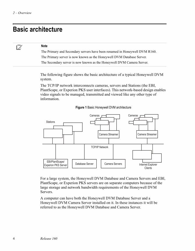
The following figure shows the basic architecture of a typical Honeywell DVM system.
The TCP/IP network interconnects cameras, servers and Stations (the EBI, PlantScape, or Experion PKS user interfaces). This network-based design enables video signals to be managed, transmitted and viewed like any other type of information.
For a large system, the Honeywell DVM Database and Camera Servers and EBI, PlantScape, or Experion PKS servers are on separate computers because of the large storage and network bandwidth requirements of the Honeywell DVM Servers.
A computer can have both the Honeywell DVM Database Server and a Honeywell DVM Camera Server installed on it. In these instances it will be referred to as the Honeywell DVM Database and Camera Server.
NoteThe Primary and Secondary servers have been renamed in Honeywell DVM R160.The Primary server is now known as the Honeywell DVM Database Server.The Secondary server is now known as the Honeywell DVM Camera Server.
Figure 1 Basic Honeywell DVM architecture
Stations
EBI/PlantScape/Experion PKS Server
TCP/IP Network
Cameras
Camera Streamer
Cameras
Camera Streamer
Database Server Camera Servers Internet ExplorerClients
Basic architecture
Honeywell Digital Video Manager User Guide 5
The Honeywell DVM Database and Camera Servers:
• Requests and receives live video from cameras
• Transmits live and recorded video to Stations and Honeywell DVM clients
• Receives camera control commands from operators (Station users) and sends them to cameras and Honeywell DVM clients
• Stores live video on hard disk
• Archives recorded video to off-line storage media
The camera streamers:
• Convert analog video output to digital format
• Stream digital video to the camera server
• Receive camera control commands from the Honeywell DVM Camera Servers and outputs them via serial connections to the camera PTZ heads
2 – Overview
6 Release 160
Integration with EBI, PlantScape, or Experion PKSHoneywell DVM is tightly integrated with three other Honeywell products:
• Honeywell Enterprise Buildings Integrator (EBI)—for building management and security-related applications.
• PlantScape—for industrial applications.
• Experion PKS—for industrial applications.
Integration with these Honeywell products provides the following benefits:
• Alarms and events can initiate recordings. These recordings can even show what happened before an alarm/event occurred, so that operators can see what preceded the incident as well as its consequences.
• Honeywell DVM shares the EBI, PlantScape, or Experion PKS user interface (Station), which means that operators do not need to learn two applications.
• Users can view Honeywell DVM videos on any Station on the network.
• Honeywell DVM uses EBI, PlantScape, or Experion PKS security features that, for example, allow you to define each operator’s viewing rights.
• Honeywell DVM system alarms and events are automatically sent to EBI, PlantScape, or Experion PKS for inclusion in the Alarm and Event Summaries.
• Recordings associated with EBI, PlantScape, or Experion PKS alarms and/or events can be viewed directly from the EBI, PlantScape, or Experion PKS Alarm or Event Summary.
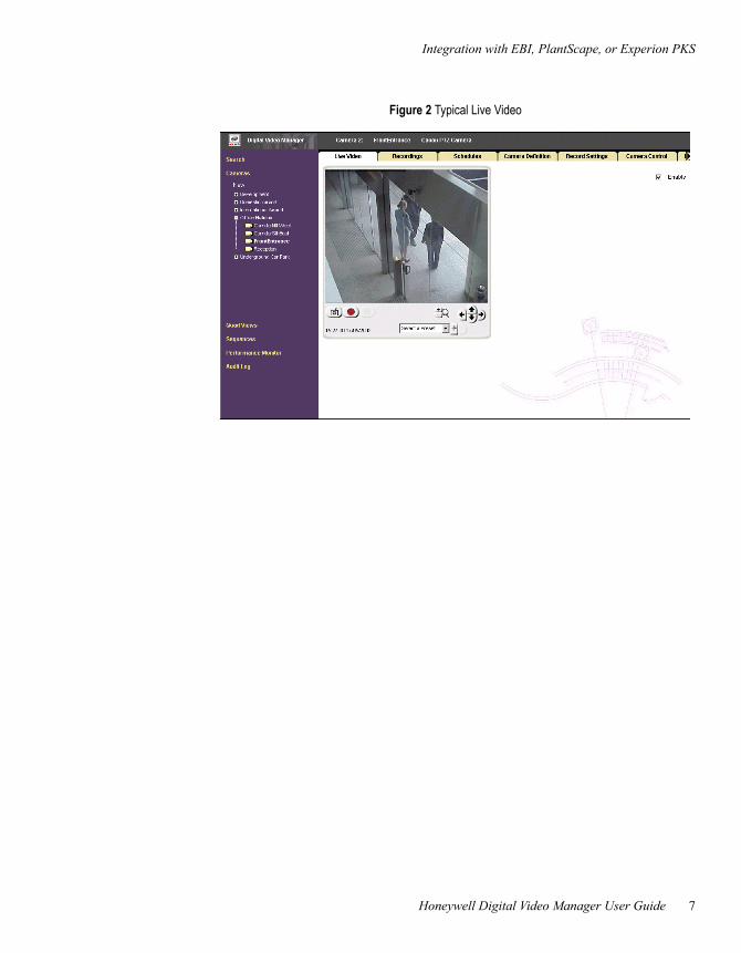
The following figure is an example of a typical live video display.
Integration with EBI, PlantScape, or Experion PKS
Honeywell Digital Video Manager User Guide 7
Figure 2 Typical Live Video

2 – Overview
8 Release 160
Honeywell Digital Video Manager User Guide 9
3Planning
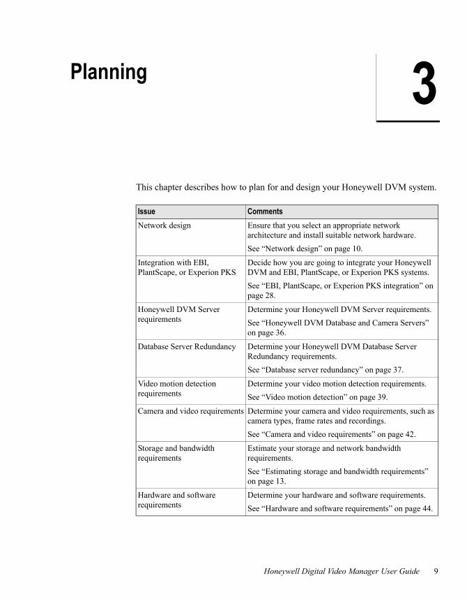
This chapter describes how to plan for and design your Honeywell DVM system.
Issue CommentsNetwork design Ensure that you select an appropriate network
architecture and install suitable network hardware.See “Network design” on page 10.
Integration with EBI, PlantScape, or Experion PKS
Decide how you are going to integrate your Honeywell DVM and EBI, PlantScape, or Experion PKS systems.See “EBI, PlantScape, or Experion PKS integration” on page 28.
Honeywell DVM Server requirements
Determine your Honeywell DVM Server requirements.See “Honeywell DVM Database and Camera Servers” on page 36.
Database Server Redundancy Determine your Honeywell DVM Database Server Redundancy requirements.See “Database server redundancy” on page 37.
Video motion detection requirements
Determine your video motion detection requirements.See “Video motion detection” on page 39.
Camera and video requirements Determine your camera and video requirements, such as camera types, frame rates and recordings.See “Camera and video requirements” on page 42.
Storage and bandwidth requirements
Estimate your storage and network bandwidth requirements.See “Estimating storage and bandwidth requirements” on page 13.
Hardware and software requirements
Determine your hardware and software requirements.See “Hardware and software requirements” on page 44.
3 – Planning
10 Release 160
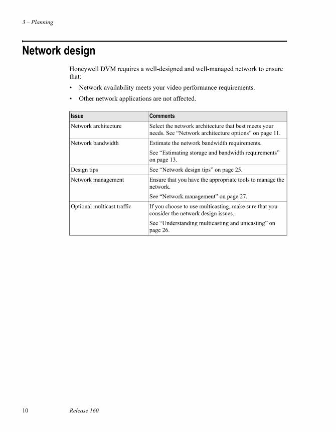
Network designHoneywell DVM requires a well-designed and well-managed network to ensure that:
• Network availability meets your video performance requirements.
• Other network applications are not affected.
Issue CommentsNetwork architecture Select the network architecture that best meets your
needs. See “Network architecture options” on page 11.
Network bandwidth Estimate the network bandwidth requirements.See “Estimating storage and bandwidth requirements” on page 13.
Design tips See “Network design tips” on page 25.
Network management Ensure that you have the appropriate tools to manage the network.See “Network management” on page 27.
Optional multicast traffic If you choose to use multicasting, make sure that you consider the network design issues.See “Understanding multicasting and unicasting” on page 26.
Network architecture options
Honeywell Digital Video Manager User Guide 11
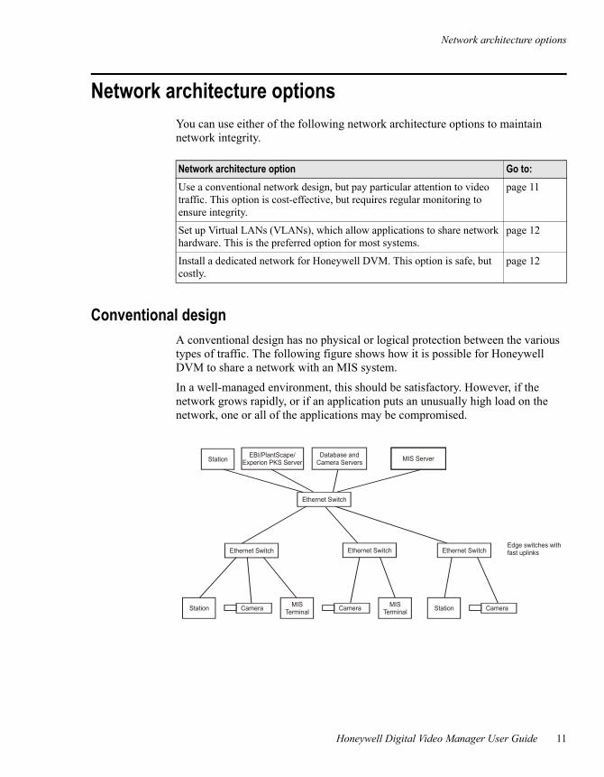
Network architecture optionsYou can use either of the following network architecture options to maintain network integrity.
Conventional designA conventional design has no physical or logical protection between the various types of traffic. The following figure shows how it is possible for Honeywell DVM to share a network with an MIS system.
In a well-managed environment, this should be satisfactory. However, if the network grows rapidly, or if an application puts an unusually high load on the network, one or all of the applications may be compromised.
Network architecture option Go to:Use a conventional network design, but pay particular attention to video traffic. This option is cost-effective, but requires regular monitoring to ensure integrity.
page 11
Set up Virtual LANs (VLANs), which allow applications to share network hardware. This is the preferred option for most systems.
page 12
Install a dedicated network for Honeywell DVM. This option is safe, but costly.
page 12
EBI/PlantScape/Experion PKS Server
Ethernet Switch Ethernet SwitchEthernet Switch
Ethernet Switch
Station
Station MISTerminal
MISTerminal StationCamera CameraCamera
MIS ServerDatabase andCamera Servers
Edge switches withfast uplinks
3 – Planning
12 Release 160
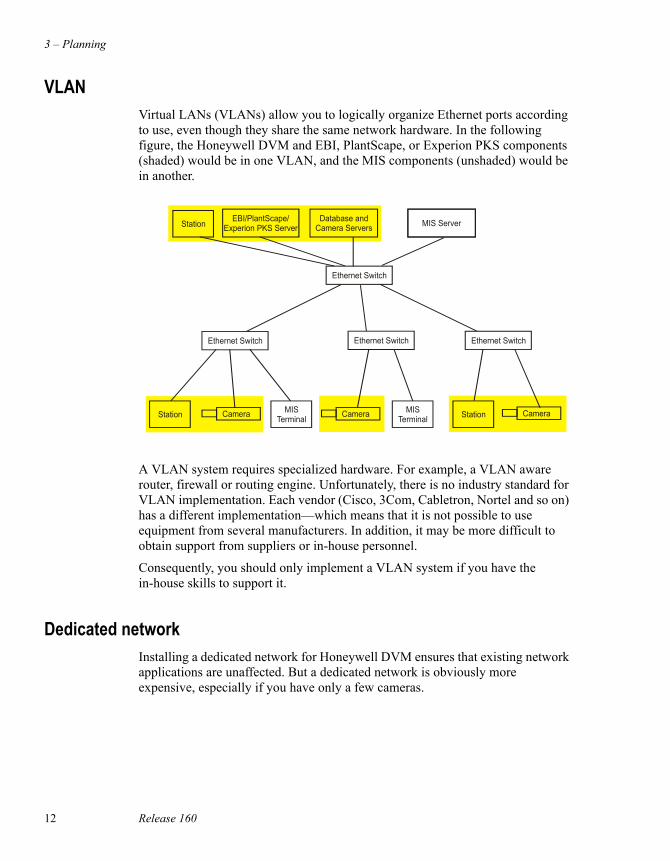
VLANVirtual LANs (VLANs) allow you to logically organize Ethernet ports according to use, even though they share the same network hardware. In the following figure, the Honeywell DVM and EBI, PlantScape, or Experion PKS components (shaded) would be in one VLAN, and the MIS components (unshaded) would be in another.
A VLAN system requires specialized hardware. For example, a VLAN aware router, firewall or routing engine. Unfortunately, there is no industry standard for VLAN implementation. Each vendor (Cisco, 3Com, Cabletron, Nortel and so on) has a different implementation—which means that it is not possible to use equipment from several manufacturers. In addition, it may be more difficult to obtain support from suppliers or in-house personnel.
Consequently, you should only implement a VLAN system if you have the in-house skills to support it.
Dedicated networkInstalling a dedicated network for Honeywell DVM ensures that existing network applications are unaffected. But a dedicated network is obviously more expensive, especially if you have only a few cameras.
EBI/PlantScape/Experion PKS Server
Ethernet Switch Ethernet SwitchEthernet Switch
Ethernet Switch
Station
Station MISTerminal
MISTerminal StationCamera
MIS ServerDatabase andCamera Servers
Camera Camera
Estimating storage and bandwidth requirements
Honeywell Digital Video Manager User Guide 13
Estimating storage and bandwidth requirementsBecause of the potentially large storage and bandwidth requirements of digital video, you need to carefully determine the image requirements on a camera-by-camera or camera group basis—in practice, you probably only need high-quality video for a few cameras.
Storage and bandwidth requirements depend on:
• Image size. For example, a 640x480 image is four times larger than a 320x240 one.
• Frame rate. The standard frame rate for smooth video is 25 fps (PAL) or 30 fps (NTSC), but much lower frame rates—even 1 fps—may be acceptable.
• Bandwidth. The greater the bandwidth, the higher the frames per second.
• Compression level. The greater the compression, the smaller the file size, but the lower the image quality.
• Image complexity. Visually complex images produce larger file sizes than visually simple images.
• Image type (color or black and white). A color image is slightly larger than its black and white equivalent.
For typical figures, see “Typical storage and bandwidth requirements” on page 14.
3 – Planning
14 Release 160
Typical storage and bandwidth requirementsThe following tables give typical storage and bandwidth requirements for different types of camera streamer.
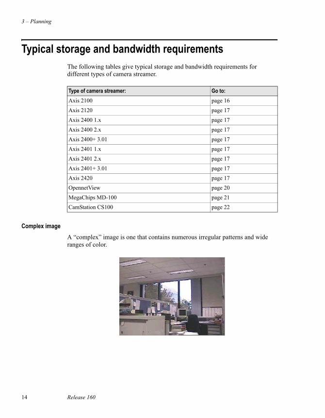
Complex imageA “complex” image is one that contains numerous irregular patterns and wide ranges of color.
Type of camera streamer: Go to:Axis 2100 page 16
Axis 2120 page 17
Axis 2400 1.x page 17
Axis 2400 2.x page 17
Axis 2400+ 3.01 page 17
Axis 2401 1.x page 17
Axis 2401 2.x page 17
Axis 2401+ 3.01 page 17
Axis 2420 page 17
OpennetView page 20
MegaChips MD-100 page 21
CamStation CS100 page 22
Typical storage and bandwidth requirements
Honeywell Digital Video Manager User Guide 15
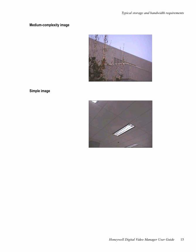
Medium-complexity image
Simple image
3 – Planning
16 Release 160
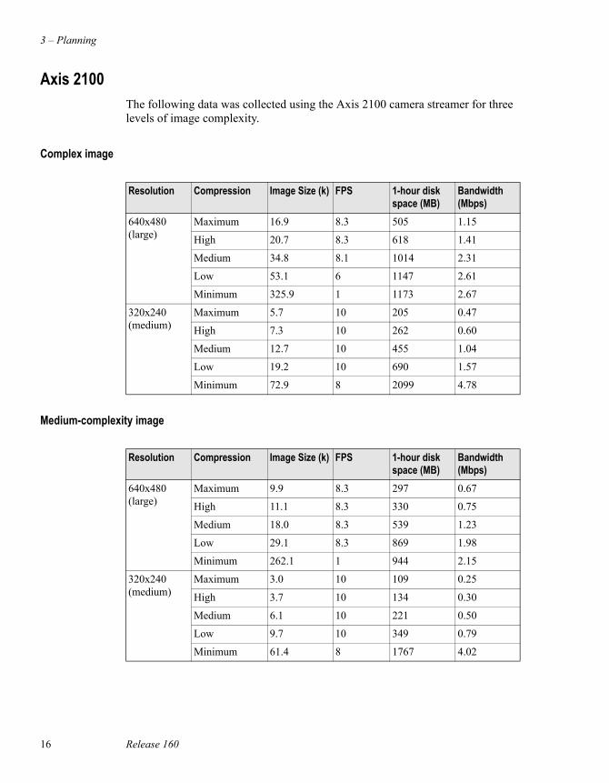
Axis 2100The following data was collected using the Axis 2100 camera streamer for three levels of image complexity.
Complex image
Medium-complexity image
Resolution Compression Image Size (k) FPS 1-hour disk space (MB)
Bandwidth (Mbps)
640x480 (large)
Maximum 16.9 8.3 505 1.15
High 20.7 8.3 618 1.41
Medium 34.8 8.1 1014 2.31
Low 53.1 6 1147 2.61
Minimum 325.9 1 1173 2.67
320x240 (medium)
Maximum 5.7 10 205 0.47
High 7.3 10 262 0.60
Medium 12.7 10 455 1.04
Low 19.2 10 690 1.57
Minimum 72.9 8 2099 4.78
Resolution Compression Image Size (k) FPS 1-hour disk space (MB)
Bandwidth (Mbps)
640x480 (large)
Maximum 9.9 8.3 297 0.67
High 11.1 8.3 330 0.75
Medium 18.0 8.3 539 1.23
Low 29.1 8.3 869 1.98
Minimum 262.1 1 944 2.15
320x240 (medium)
Maximum 3.0 10 109 0.25
High 3.7 10 134 0.30
Medium 6.1 10 221 0.50
Low 9.7 10 349 0.79
Minimum 61.4 8 1767 4.02
Typical storage and bandwidth requirements
Honeywell Digital Video Manager User Guide 17
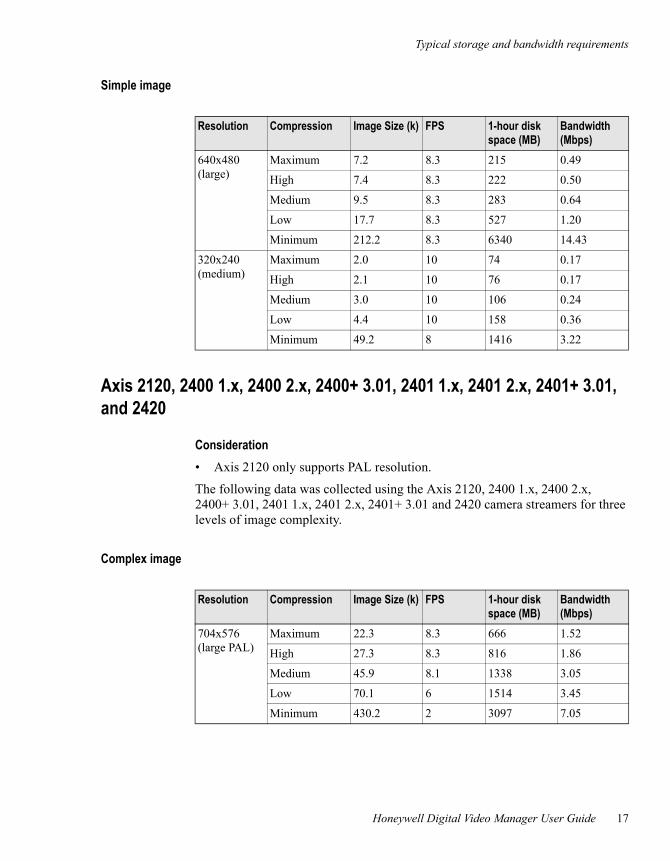
Simple image
Axis 2120, 2400 1.x, 2400 2.x, 2400+ 3.01, 2401 1.x, 2401 2.x, 2401+ 3.01, and 2420
Consideration• Axis 2120 only supports PAL resolution.
The following data was collected using the Axis 2120, 2400 1.x, 2400 2.x, 2400+ 3.01, 2401 1.x, 2401 2.x, 2401+ 3.01 and 2420 camera streamers for three levels of image complexity.
Complex image
Resolution Compression Image Size (k) FPS 1-hour disk space (MB)
Bandwidth (Mbps)
640x480 (large)
Maximum 7.2 8.3 215 0.49
High 7.4 8.3 222 0.50
Medium 9.5 8.3 283 0.64
Low 17.7 8.3 527 1.20
Minimum 212.2 8.3 6340 14.43
320x240 (medium)
Maximum 2.0 10 74 0.17
High 2.1 10 76 0.17
Medium 3.0 10 106 0.24
Low 4.4 10 158 0.36
Minimum 49.2 8 1416 3.22
Resolution Compression Image Size (k) FPS 1-hour disk space (MB)
Bandwidth (Mbps)
704x576 (large PAL)
Maximum 22.3 8.3 666 1.52
High 27.3 8.3 816 1.86
Medium 45.9 8.1 1338 3.05
Low 70.1 6 1514 3.45
Minimum 430.2 2 3097 7.05
3 – Planning
18 Release 160
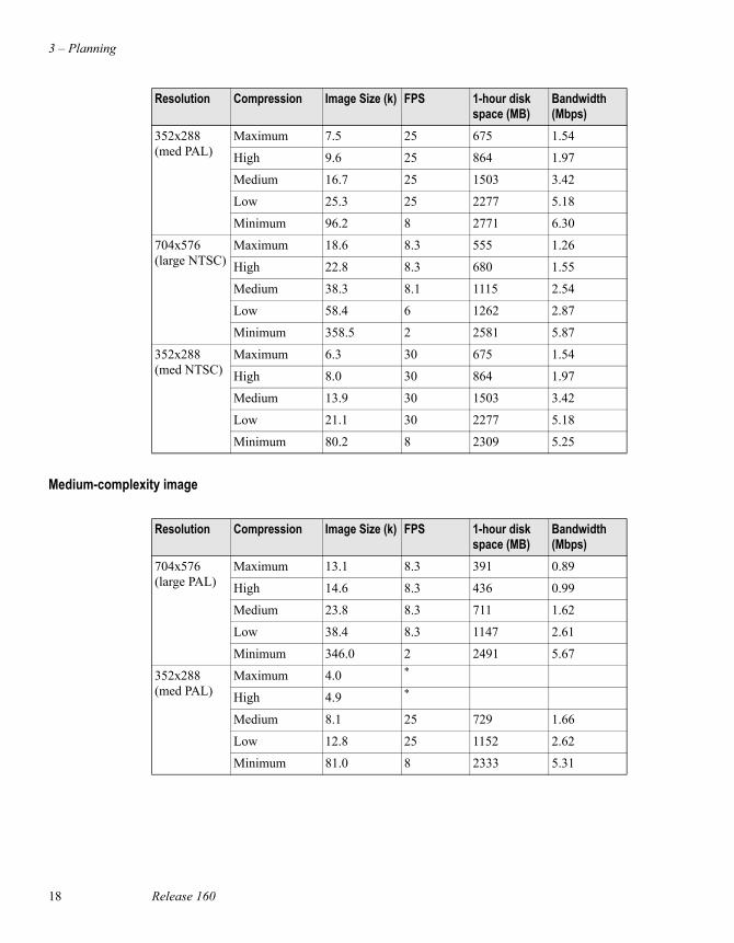
Medium-complexity image
352x288 (med PAL)
Maximum 7.5 25 675 1.54
High 9.6 25 864 1.97
Medium 16.7 25 1503 3.42
Low 25.3 25 2277 5.18
Minimum 96.2 8 2771 6.30
704x576 (large NTSC)
Maximum 18.6 8.3 555 1.26
High 22.8 8.3 680 1.55
Medium 38.3 8.1 1115 2.54
Low 58.4 6 1262 2.87
Minimum 358.5 2 2581 5.87
352x288 (med NTSC)
Maximum 6.3 30 675 1.54
High 8.0 30 864 1.97
Medium 13.9 30 1503 3.42
Low 21.1 30 2277 5.18
Minimum 80.2 8 2309 5.25
Resolution Compression Image Size (k) FPS 1-hour disk space (MB)
Bandwidth (Mbps)
Resolution Compression Image Size (k) FPS 1-hour disk space (MB)
Bandwidth (Mbps)
704x576 (large PAL)
Maximum 13.1 8.3 391 0.89
High 14.6 8.3 436 0.99
Medium 23.8 8.3 711 1.62
Low 38.4 8.3 1147 2.61
Minimum 346.0 2 2491 5.67
352x288 (med PAL)
Maximum 4.0 *
High 4.9 *
Medium 8.1 25 729 1.66
Low 12.8 25 1152 2.62
Minimum 81.0 8 2333 5.31
Typical storage and bandwidth requirements
Honeywell Digital Video Manager User Guide 19
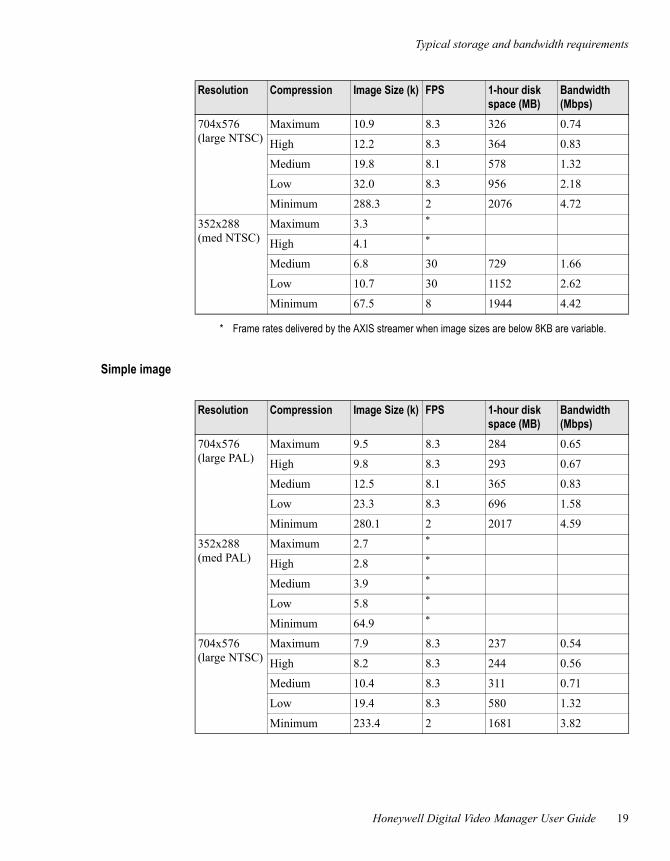
Simple image
704x576 (large NTSC)
Maximum 10.9 8.3 326 0.74
High 12.2 8.3 364 0.83
Medium 19.8 8.1 578 1.32
Low 32.0 8.3 956 2.18
Minimum 288.3 2 2076 4.72
352x288 (med NTSC)
Maximum 3.3 *
High 4.1 *
Medium 6.8 30 729 1.66
Low 10.7 30 1152 2.62
Minimum 67.5 8 1944 4.42
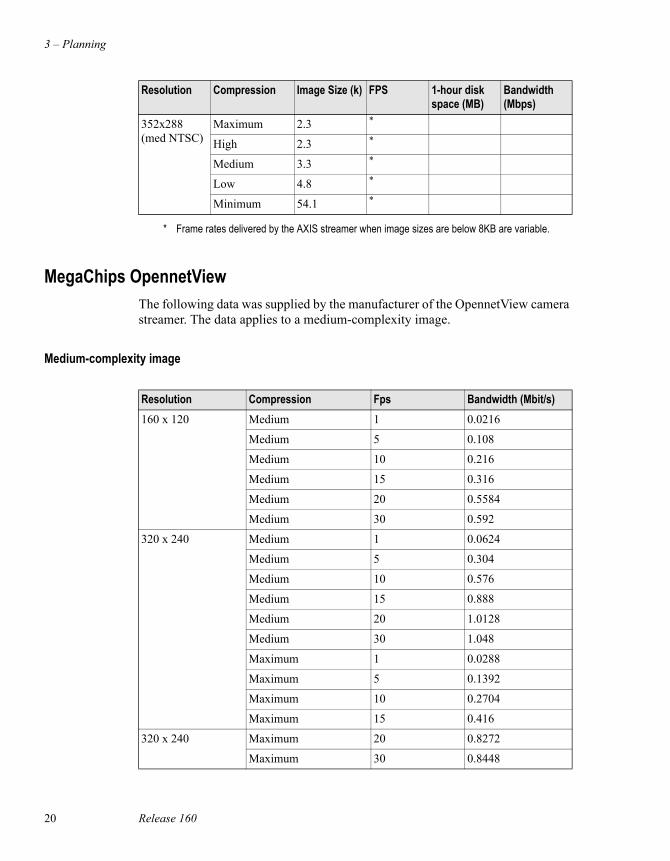
* Frame rates delivered by the AXIS streamer when image sizes are below 8KB are variable.
Resolution Compression Image Size (k) FPS 1-hour disk space (MB)
Bandwidth (Mbps)
Resolution Compression Image Size (k) FPS 1-hour disk space (MB)
Bandwidth (Mbps)
704x576 (large PAL)
Maximum 9.5 8.3 284 0.65
High 9.8 8.3 293 0.67
Medium 12.5 8.1 365 0.83
Low 23.3 8.3 696 1.58
Minimum 280.1 2 2017 4.59
352x288 (med PAL)
Maximum 2.7 *
High 2.8 *
Medium 3.9 *
Low 5.8 *
Minimum 64.9 *
704x576 (large NTSC)
Maximum 7.9 8.3 237 0.54
High 8.2 8.3 244 0.56
Medium 10.4 8.3 311 0.71
Low 19.4 8.3 580 1.32
Minimum 233.4 2 1681 3.82
3 – Planning
20 Release 160
MegaChips OpennetViewThe following data was supplied by the manufacturer of the OpennetView camera streamer. The data applies to a medium-complexity image.
Medium-complexity image
352x288 (med NTSC)
Maximum 2.3 *
High 2.3 *
Medium 3.3 *
Low 4.8 *
Minimum 54.1 *
* Frame rates delivered by the AXIS streamer when image sizes are below 8KB are variable.
Resolution Compression Image Size (k) FPS 1-hour disk space (MB)
Bandwidth (Mbps)
Resolution Compression Fps Bandwidth (Mbit/s)160 x 120 Medium 1 0.0216
Medium 5 0.108
Medium 10 0.216
Medium 15 0.316
Medium 20 0.5584
Medium 30 0.592
320 x 240 Medium 1 0.0624
Medium 5 0.304
Medium 10 0.576
Medium 15 0.888
Medium 20 1.0128
Medium 30 1.048
Maximum 1 0.0288
Maximum 5 0.1392
Maximum 10 0.2704
Maximum 15 0.416
320 x 240 Maximum 20 0.8272
Maximum 30 0.8448
Typical storage and bandwidth requirements
Honeywell Digital Video Manager User Guide 21
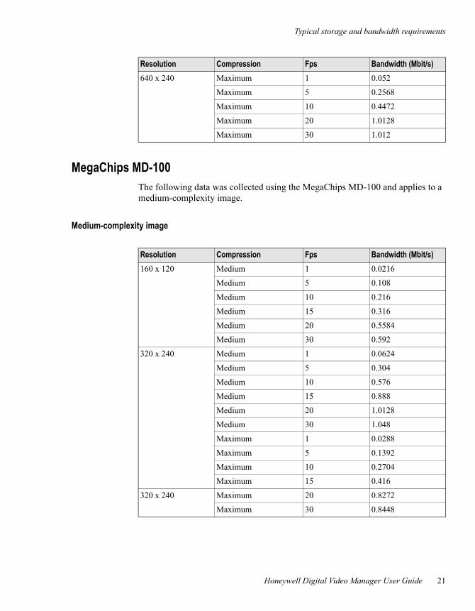
MegaChips MD-100The following data was collected using the MegaChips MD-100 and applies to a medium-complexity image.
Medium-complexity image
640 x 240 Maximum 1 0.052
Maximum 5 0.2568
Maximum 10 0.4472
Maximum 20 1.0128
Maximum 30 1.012
Resolution Compression Fps Bandwidth (Mbit/s)
Resolution Compression Fps Bandwidth (Mbit/s)160 x 120 Medium 1 0.0216
Medium 5 0.108
Medium 10 0.216
Medium 15 0.316
Medium 20 0.5584
Medium 30 0.592
320 x 240 Medium 1 0.0624
Medium 5 0.304
Medium 10 0.576
Medium 15 0.888
Medium 20 1.0128
Medium 30 1.048
Maximum 1 0.0288
Maximum 5 0.1392
Maximum 10 0.2704
Maximum 15 0.416
320 x 240 Maximum 20 0.8272
Maximum 30 0.8448
3 – Planning
22 Release 160
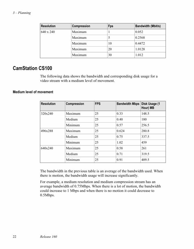
CamStation CS100The following data shows the bandwidth and corresponding disk usage for a video stream with a medium level of movement.
Medium level of movement
The bandwidth in the previous table is an average of the bandwidth used. When there is motion, the bandwidth usage will increase significantly.
For example, a medium resolution and medium compression stream has an average bandwidth of 0.75Mbps. When there is a lot of motion, the bandwidth could increase to 1 Mbps and when there is no motion it could decrease to 0.5Mbps.
640 x 240 Maximum 1 0.052
Maximum 5 0.2568
Maximum 10 0.4472
Maximum 20 1.0128
Maximum 30 1.012
Resolution Compression Fps Bandwidth (Mbit/s)
Resolution Compression FPS Bandwidth Mbps Disk Usage (1 Hour) MB
320x240 Maximum 25 0.33 148.5
Medium 25 0.40 180
Minimum 25 0.57 256.5
496x288 Maximum 25 0.624 280.8
Medium 25 0.75 337.5
Minimum 25 1.02 459
640x240 Maximum 25 0.58 261
Medium 25 0.71 319.5
Minimum 25 0.91 409.5
Typical storage and bandwidth requirements
Honeywell Digital Video Manager User Guide 23
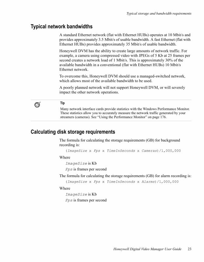
Typical network bandwidthsA standard Ethernet network (flat with Ethernet HUBs) operates at 10 Mbit/s and provides approximately 3.5 Mbit/s of usable bandwidth. A fast Ethernet (flat with Ethernet HUBs) provides approximately 35 Mbit/s of usable bandwidth.
Honeywell DVM has the ability to create large amounts of network traffic. For example, a camera using compressed video with JPEGs of 5 Kb at 25 frames per second creates a network load of 1 Mbit/s. This is approximately 30% of the available bandwidth in a conventional (flat with Ethernet HUBs) 10 Mbit/s Ethernet network.
To overcome this, Honeywell DVM should use a managed-switched network, which allows most of the available bandwidth to be used.
A poorly planned network will not support Honeywell DVM, or will severely impact the other network operations.
Calculating disk storage requirementsThe formula for calculating the storage requirements (GB) for background recording is:
(ImageSize x Fps x TimeInSeconds x Cameras)/1,000,000
WhereImageSize is KbFps is frames per second
The formula for calculating the storage requirements (GB) for alarm recording is:(ImageSize x Fps x TimeInSeconds x Alarms)/1,000,000
WhereImageSize is KbFps is frames per second
TipMany network interface cards provide statistics with the Windows Performance Monitor. These statistics allow you to accurately measure the network traffic generated by your streamers (cameras). See “Using the Performance Monitor” on page 176.
3 – Planning
24 Release 160
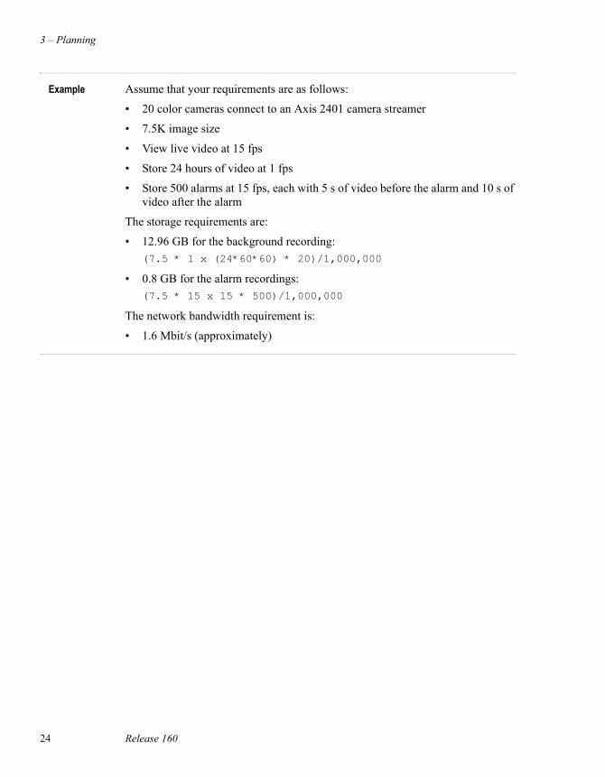
Example Assume that your requirements are as follows:
• 20 color cameras connect to an Axis 2401 camera streamer
• 7.5K image size
• View live video at 15 fps
• Store 24 hours of video at 1 fps
• Store 500 alarms at 15 fps, each with 5 s of video before the alarm and 10 s of video after the alarm
The storage requirements are:
• 12.96 GB for the background recording:(7.5 * 1 x (24*60*60) * 20)/1,000,000
• 0.8 GB for the alarm recordings:(7.5 * 15 x 15 * 500)/1,000,000
The network bandwidth requirement is:
• 1.6 Mbit/s (approximately)
Network design tips
Honeywell Digital Video Manager User Guide 25
Network design tips• Use ATM, Gigabit or Fast Ethernet.
• Minimize the number of switches.
• Use switches, not hubs.
• Minimize the number of routers.
• Do not use 10 Mbit/s hubs. 100 Mbit/s hubs may be acceptable, depending on the rest of the network equipment.
• Isolate, as far as possible, video traffic for individual Honeywell DVM Camera Servers.
• Isolate, as far as possible, EBI, PlantScape, or Experion PKS from traffic between camera streamers and Honeywell DVM Camera Servers.
• Place camera streamer traffic and Station traffic on different LANs or VLANs.
• Consider placing multiple network cards in the Honeywell DVM Servers. Camera streamers can reside on more than one VLAN.
• Consider using full-duplex Ethernet.
• Consider using load-sharing network cards in the Honeywell DVM Database and Camera Servers.
3 – Planning
26 Release 160
Understanding multicasting and unicastingHoneywell DVM uses two transmission techniques:
• Multicasting. This involves sending information from one device to multiple devices. For example, from the Honeywell DVM Server(s) to two Stations.
• Unicasting. This involves sending information to only one device.
Although multicasting is a very useful transmission technique, it can have very significant effects on the network. Without special configuration, most equipment sends multicast traffic to all devices in the network, resulting in high network utilization across the whole network, rather than in only the relevant segments.
Honeywell DVM uses multicasting and unicasting as follows:
• Transmission from the camera streamer to the Honeywell DVM Camera Server is unicast.
• Transmission from the Honeywell DVM Camera Server to Station(s) can be either unicast or multicast:
- Unicast is always used for playing back recorded video.
- Live video viewing can be configured on a camera-by-camera basis to be either multicast or unicast. Multicast is more efficient because several Stations can view the same live video without increasing the network usage. Unicast is less efficient because it requires a separate network stream for every Station.
Sophisticated network switches are required to correctly handle multicast traffic. Note that some network switches, such as LANE1 ATM, turn a multicast message in to a broadcast one, which may quickly overload the network.
Routers have special configuration requirements to enable them to handle multicast traffic. Contact your vendor for these configuration requirements.
Network management
Honeywell Digital Video Manager User Guide 27
Network managementNetwork management is a complex topic that is beyond the scope of this guide. However, Honeywell DVM requires an appropriate set of network management tools that provide information such as:
• Network utilization, including real-time and history reports.
• Warning if utilization reaches a user-defined threshold.
• Notification if a switch or camera fails.
3 – Planning
28 Release 160
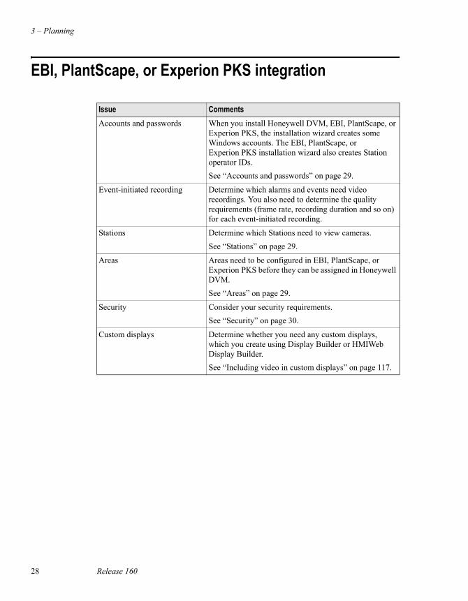
EBI, PlantScape, or Experion PKS integration
Issue CommentsAccounts and passwords When you install Honeywell DVM, EBI, PlantScape, or
Experion PKS, the installation wizard creates some Windows accounts. The EBI, PlantScape, or Experion PKS installation wizard also creates Station operator IDs.See “Accounts and passwords” on page 29.
Event-initiated recording Determine which alarms and events need video recordings. You also need to determine the quality requirements (frame rate, recording duration and so on) for each event-initiated recording.
Stations Determine which Stations need to view cameras.See “Stations” on page 29.
Areas Areas need to be configured in EBI, PlantScape, or Experion PKS before they can be assigned in Honeywell DVM.See “Areas” on page 29.
Security Consider your security requirements.See “Security” on page 30.
Custom displays Determine whether you need any custom displays, which you create using Display Builder or HMIWeb Display Builder. See “Including video in custom displays” on page 117.
EBI, PlantScape, or Experion PKS integration
Honeywell Digital Video Manager User Guide 29
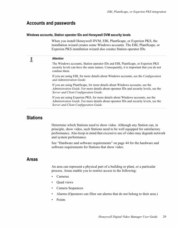
Accounts and passwords
Windows accounts, Station operator IDs and Honeywell DVM security levelsWhen you install Honeywell DVM, EBI, PlantScape, or Experion PKS, the installation wizard creates some Windows accounts. The EBI, PlantScape, or Experion PKS installation wizard also creates Station operator IDs.
StationsDetermine which Stations need to show video. Although any Station can, in principle, show video, such Stations need to be well equipped for satisfactory performance. Also keep in mind that excessive use of video may degrade network and system performance.
See “Hardware and software requirements” on page 44 for the hardware and software requirements for Stations that show video.
AreasAn area can represent a physical part of a building or plant, or a particular process. Areas enable you to restrict access to the following:
• Cameras
• Quad views
• Camera Sequences
• Alarms (Operators can filter out alarms that do not belong to their area.)
• Points
AttentionThe Windows accounts, Station operator IDs and EBI, PlantScape, or Experion PKS security levels can have the same names. Consequently, it is important that you do not confuse them.If you are using EBI, for more details about Windows accounts, see the Configuration and Administration Guide. If you are using PlantScape, for more details about Windows accounts, see the Administration Guide. For more details about operator IDs and security levels, see the Server and Client Configuration Guide.If you are using Experion PKS, for more details about Windows accounts, see the Administration Guide. For more details about operator IDs and security levels, see the Server and Client Configuration Guide.
3 – Planning
30 Release 160
• Stations (A Station assigned to a particular area can only access points, custom displays and reports that are assigned to the same area.)
• Operators, providing you use operator-based security
• Custom displays
• Reports
Areas must be configured within EBI, PlantScape, or Experion PKS before you can assign them in Honeywell DVM.
For more information about areas, refer to the EBI, PlantScape, or Experion PKS Configuration Guide.
SecurityHoneywell DVM supports three types of security methods. They are:
• Operator-based (page 31)
• Station-based (page 33)
• Internet Explorer security (page 35)
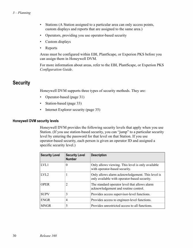
Honeywell DVM security levelsHoneywell DVM provides the following security levels that apply when you use Station. (If you use station-based security, you can “jump” to a particular security level by entering the password for that level on that Station. If you use operator-based security, each person is given an operator ID and assigned a specific security level.)
Security Level Security Level Number
Description
LVL1 0 Only allows viewing. This level is only available with operator-based security.
LVL2 1 Only allows alarm acknowledgement. This level is only available with operator-based security.
OPER 2 The standard operator level that allows alarm acknowledgement and routine control.
SUPV 3 Provides access supervisor-level functions.
ENGR 4 Provides access to engineer-level functions.
MNGR 5 Provides unrestricted access to all functions.
EBI, PlantScape, or Experion PKS integration
Honeywell Digital Video Manager User Guide 31
Operator-based security
Prerequisites• Operator-based security must be configured within EBI, PlantScape, or
Experion PKS, before you can configure security for Honeywell DVM.
If you use operator-based security, each user is assigned an ID and password (as well as an appropriate security level). Each user must log on to Station before being able to use it.
If you are using EBI with Honeywell DVM, refer to the EBI Configuration and Administration Guide for more information about operator-based security.
If you are using PlantScape with Honeywell DVM, refer to the PlantScape Administration and Startup Guide for more information about operator-based security.
If you are using Experion PKS with Honeywell DVM, refer to the Experion PKS Administration and Startup Guide for more information about operator-based security.
3 – Planning
32 Release 160
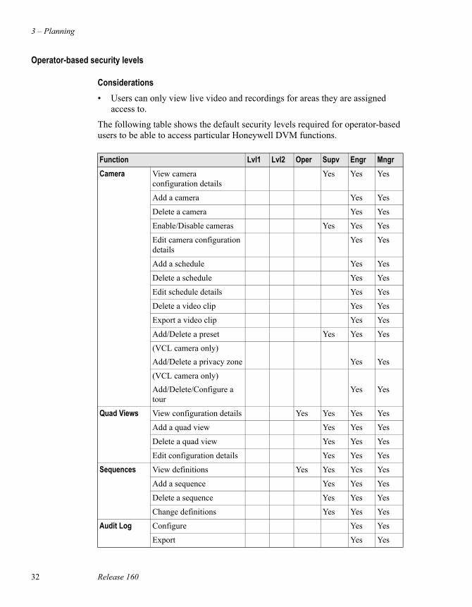
Operator-based security levels
Considerations• Users can only view live video and recordings for areas they are assigned
access to.
The following table shows the default security levels required for operator-based users to be able to access particular Honeywell DVM functions.
Function Lvl1 Lvl2 Oper Supv Engr MngrCamera View camera
configuration detailsYes Yes Yes
Add a camera Yes Yes
Delete a camera Yes Yes
Enable/Disable cameras Yes Yes Yes
Edit camera configuration details
Yes Yes
Add a schedule Yes Yes
Delete a schedule Yes Yes
Edit schedule details Yes Yes
Delete a video clip Yes Yes
Export a video clip Yes Yes
Add/Delete a preset Yes Yes Yes
(VCL camera only)Add/Delete a privacy zone Yes Yes
(VCL camera only)Add/Delete/Configure a tour
Yes Yes
Quad Views View configuration details Yes Yes Yes Yes
Add a quad view Yes Yes Yes
Delete a quad view Yes Yes Yes
Edit configuration details Yes Yes Yes
Sequences View definitions Yes Yes Yes Yes
Add a sequence Yes Yes Yes
Delete a sequence Yes Yes Yes
Change definitions Yes Yes Yes
Audit Log Configure Yes Yes
Export Yes Yes
EBI, PlantScape, or Experion PKS integration
Honeywell Digital Video Manager User Guide 33
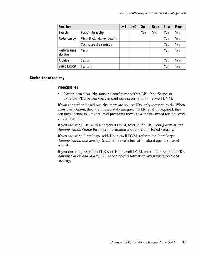
Station-based security
Prerequisites• Station-based security must be configured within EBI, PlantScape, or
Experion PKS before you can configure security in Honeywell DVM.
If you use station-based security, there are no user IDs, only security levels. When users start station, they are immediately assigned OPER level. If required, they can then change to a higher level providing they know the password for that level on that Station.
If you are using EBI with Honeywell DVM, refer to the EBI Configuration and Administration Guide for more information about operator-based security.
If you are using PlantScape with Honeywell DVM, refer to the PlantScape Administration and Startup Guide for more information about operator-based security.
If you are using Experion PKS with Honeywell DVM, refer to the Experion PKS Administration and Startup Guide for more information about operator-based security.
Search Search for a clip Yes Yes Yes Yes
Redundancy View Redundancy details Yes Yes
Configure the settings Yes Yes
Performance Monitor
View Yes Yes
Archive Perform Yes Yes
Video Export Perform Yes Yes
Function Lvl1 Lvl2 Oper Supv Engr Mngr
3 – Planning
34 Release 160
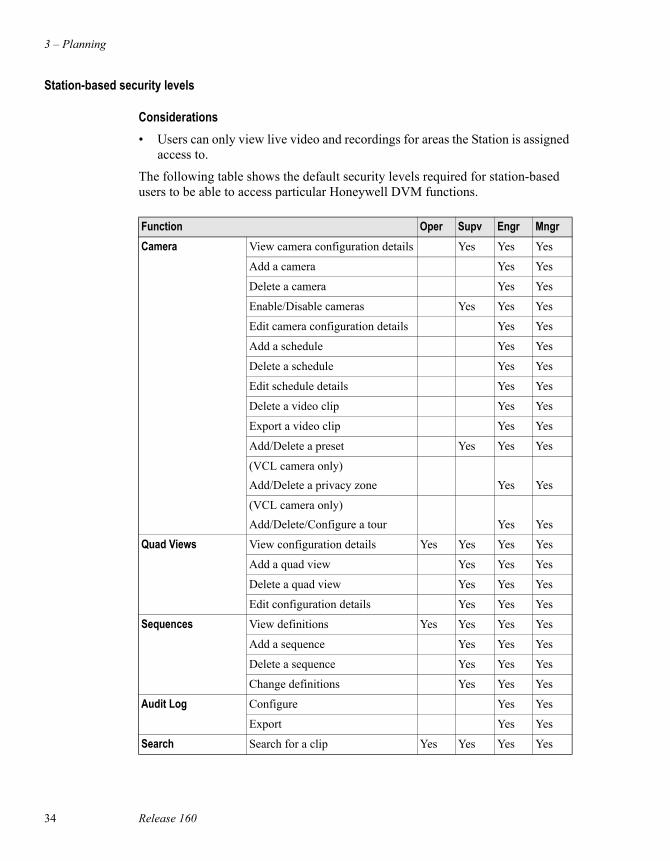
Station-based security levels
Considerations• Users can only view live video and recordings for areas the Station is assigned
access to.
The following table shows the default security levels required for station-based users to be able to access particular Honeywell DVM functions.
Function Oper Supv Engr MngrCamera View camera configuration details Yes Yes Yes
Add a camera Yes Yes
Delete a camera Yes Yes
Enable/Disable cameras Yes Yes Yes
Edit camera configuration details Yes Yes
Add a schedule Yes Yes
Delete a schedule Yes Yes
Edit schedule details Yes Yes
Delete a video clip Yes Yes
Export a video clip Yes Yes
Add/Delete a preset Yes Yes Yes
(VCL camera only)Add/Delete a privacy zone Yes Yes
(VCL camera only)Add/Delete/Configure a tour Yes Yes
Quad Views View configuration details Yes Yes Yes Yes
Add a quad view Yes Yes Yes
Delete a quad view Yes Yes Yes
Edit configuration details Yes Yes Yes
Sequences View definitions Yes Yes Yes Yes
Add a sequence Yes Yes Yes
Delete a sequence Yes Yes Yes
Change definitions Yes Yes Yes
Audit Log Configure Yes Yes
Export Yes Yes
Search Search for a clip Yes Yes Yes Yes
EBI, PlantScape, or Experion PKS integration
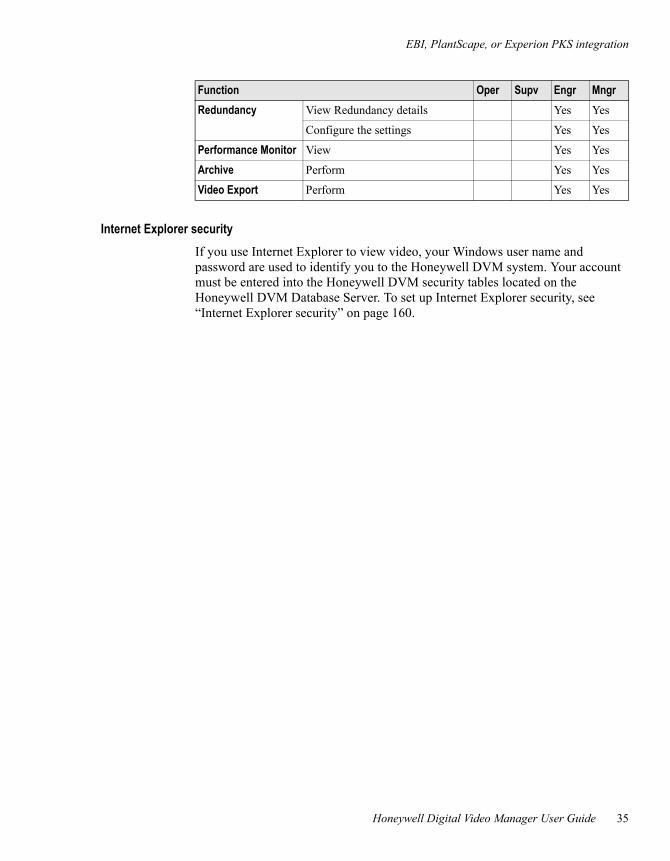
Honeywell Digital Video Manager User Guide 35
Internet Explorer securityIf you use Internet Explorer to view video, your Windows user name and password are used to identify you to the Honeywell DVM system. Your account must be entered into the Honeywell DVM security tables located on the Honeywell DVM Database Server. To set up Internet Explorer security, see “Internet Explorer security” on page 160.
Redundancy View Redundancy details Yes Yes
Configure the settings Yes Yes
Performance Monitor View Yes Yes
Archive Perform Yes Yes
Video Export Perform Yes Yes
Function Oper Supv Engr Mngr
3 – Planning
36 Release 160
Honeywell DVM Database and Camera ServersA computer can have both the Honeywell DVM Database Server and a Honeywell DVM Camera Server installed. In these instances it will be referred to as the Honeywell DVM Database and Camera Server.
Honeywell DVM Database ServersThe Honeywell DVM Database Server is responsible for:
• Storing the configuration and runtime information of the Honeywell DVM system.
• Distributing state information to the clients.
• Accepting requests from Honeywell DVM clients to view video.
Honeywell DVM Camera ServersThe Honeywell DVM Camera Servers are responsible for communications with the cameras, including:
• Connecting to the video source
• Transmitting video from the cameras to the Honeywell DVM clients
• Recording video
• Video motion detection
• Notifying the Honeywell DVM Database Server of the system state
To estimate the requirements for each Honeywell DVM Server, use the figures provided in “Typical storage and bandwidth requirements” on page 14.
For information about determining the storage requirements for each Honeywell DVM Camera Server, see “Estimating storage and bandwidth requirements” on page 13.
Database server redundancy
Honeywell Digital Video Manager User Guide 37
Database server redundancy
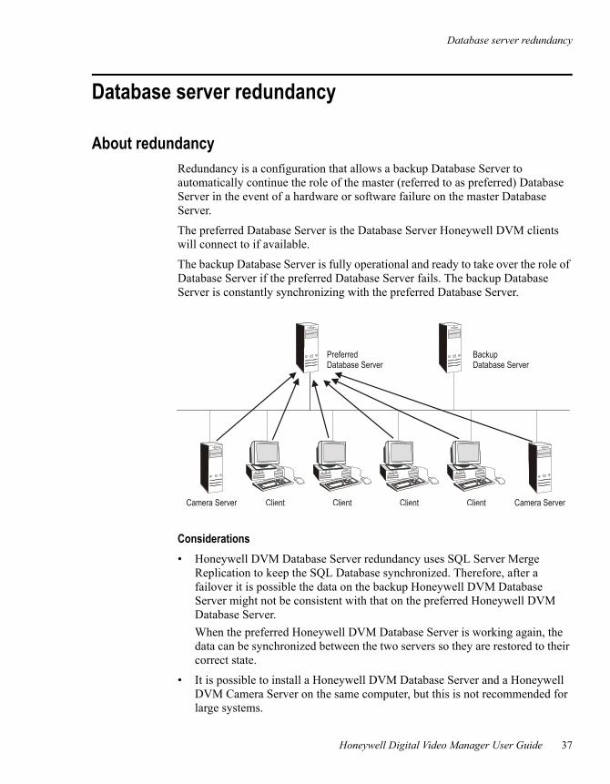
About redundancyRedundancy is a configuration that allows a backup Database Server to automatically continue the role of the master (referred to as preferred) Database Server in the event of a hardware or software failure on the master Database Server.
The preferred Database Server is the Database Server Honeywell DVM clients will connect to if available.
The backup Database Server is fully operational and ready to take over the role of Database Server if the preferred Database Server fails. The backup Database Server is constantly synchronizing with the preferred Database Server.
Considerations• Honeywell DVM Database Server redundancy uses SQL Server Merge
Replication to keep the SQL Database synchronized. Therefore, after a failover it is possible the data on the backup Honeywell DVM Database Server might not be consistent with that on the preferred Honeywell DVM Database Server.When the preferred Honeywell DVM Database Server is working again, the data can be synchronized between the two servers so they are restored to their correct state.
• It is possible to install a Honeywell DVM Database Server and a Honeywell DVM Camera Server on the same computer, but this is not recommended for large systems.
ClientCamera Server Client Client Camera ServerClient
PreferredDatabase Server
BackupDatabase Server
3 – Planning
38 Release 160
• For disaster prevention, consider having your redundant Honeywell DVM Database Server in a different geographical location.
• After failover, it is very important that the connection between the Honeywell DVM Database Servers is restored as soon as possible. While only one Honeywell DVM Database Server is running, it buffers information which is to be published to the other Honeywell DVM Database Server. After 14 days, the Merge Agent will stop running and the Honeywell DVM Database Server will need to be re-initialized.
• The date and time on all servers need to be synchronized to ensure that all dates and/or times associated with events in the database are consistent between servers.
Video motion detection
Honeywell Digital Video Manager User Guide 39
Video motion detectionConsiderations• Server-side motion detection is not supported for the CamStation CS100
streamer.
Video motion detection is performed on either the Honeywell DVM Camera Servers or the camera streamers.
When it is performed by the Honeywell DVM Camera Servers it is known as server-side motion detection and when it is performed by the camera streamer it is known as streamer-side motion detection.
Server-side motion detection requires the video to be streamed from the streamer to the Honeywell DVM Camera Server. The Honeywell DVM Camera Server then decompresses the video and performs motion detection on each frame. This process may use significant systems resources.
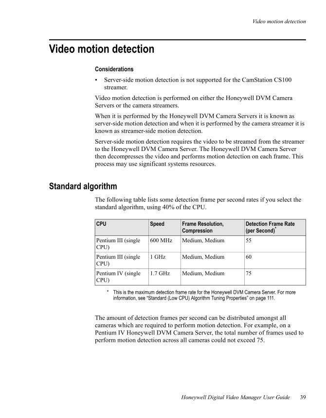
Standard algorithmThe following table lists some detection frame per second rates if you select the standard algorithm, using 40% of the CPU.
The amount of detection frames per second can be distributed amongst all cameras which are required to perform motion detection. For example, on a Pentium IV Honeywell DVM Camera Server, the total number of frames used to perform motion detection across all cameras could not exceed 75.
CPU Speed Frame Resolution, Compression
Detection Frame Rate (per Second)*
Pentium III (single CPU)
600 MHz Medium, Medium 55
Pentium III (single CPU)
1 GHz Medium, Medium 60
Pentium IV (single CPU)
1.7 GHz Medium, Medium 75
* This is the maximum detection frame rate for the Honeywell DVM Camera Server. For more information, see “Standard (Low CPU) Algorithm Tuning Properties” on page 111.
3 – Planning
40 Release 160
Example If your server is a Pentium IV 1.7 GHz, there can be 25 cameras doing 3 detection frames per second each, or 15 cameras doing 5 detection frames per second. So long as the total sum of detection frames per second does not exceed 75.
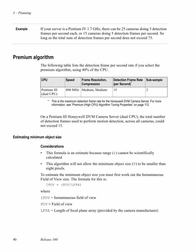
Premium algorithmThe following table lists the detection frame per second rate if you select the premium algorithm, using 40% of the CPU.
On a Pentium III Honeywell DVM Camera Server (dual CPU), the total number of detection frames used to perform motion detection, across all cameras, could not exceed 15.
Estimating minimum object size
Considerations• This formula is an estimate because range (r) cannot be scientifically
calculated.
• This algorithm will not allow the minimum object size (P) to be smaller than eight pixels.
To estimate the minimum object size you must first work out the Instantaneous Field of View size. The formula for this is:
IFOV = (FOV/LFPA)
where
IFOV = Instantaneous field of view
FOV = Field of view
LFPA = Length of focal plane array (provided by the camera manufacturer)
CPU Speed Frame Resolution, Compression
Detection Frame Rate (per Second)*
Sub-sample
Pentium III (dual CPU)
800 MHz Medium, Medium 15 2
* This is the maximum detection frame rate for the Honeywell DVM Camera Server. For more information, see “Premium (High CPU) Algorithm Tuning Properties” on page 112.
Video motion detection
Honeywell Digital Video Manager User Guide 41
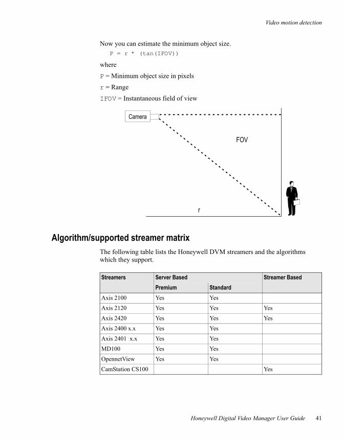
Now you can estimate the minimum object size.P = r * (tan(IFOV))
where
P = Minimum object size in pixels
r = Range
IFOV = Instantaneous field of view
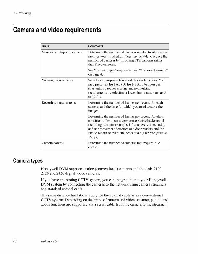
Algorithm/supported streamer matrixThe following table lists the Honeywell DVM streamers and the algorithms which they support.
Camera
FOV
r
Streamers Server Based Streamer BasedPremium Standard
Axis 2100 Yes Yes
Axis 2120 Yes Yes Yes
Axis 2420 Yes Yes Yes
Axis 2400 x.x Yes Yes
Axis 2401 x.x Yes Yes
MD100 Yes Yes
OpennetView Yes Yes
CamStation CS100 Yes
3 – Planning
42 Release 160
Camera and video requirements
Camera typesHoneywell DVM supports analog (conventional) cameras and the Axis 2100, 2120 and 2420 digital video cameras.
If you have an existing CCTV system, you can integrate it into your Honeywell DVM system by connecting the cameras to the network using camera streamers and standard coaxial cable.
The same distance limitations apply for the coaxial cable as in a conventional CCTV system. Depending on the brand of camera and video streamer, pan tilt and zoom functions are supported via a serial cable from the camera to the streamer.
Issue CommentsNumber and types of camera Determine the number of cameras needed to adequately
monitor your installation. You may be able to reduce the number of cameras by installing PTZ cameras rather than fixed cameras.See “Camera types” on page 42 and “Camera streamers” on page 43.
Viewing requirements Select an appropriate frame rate for each camera. You may prefer 25 fps PAL (30 fps NTSC), but you can substantially reduce storage and networking requirements by selecting a lower frame rate, such as 5 or 15 fps.
Recording requirements Determine the number of frames per second for each camera, and the time for which you need to store the images.Determine the number of frames per second for alarm conditions. Try to set a very conservative background recording rate (for example, 1 frame every 2 seconds), and use movement detectors and door readers and the like to record relevant incidents at a higher rate (such as 15 fps).
Camera control Determine the number of cameras that require PTZ control.
Camera and video requirements
Honeywell Digital Video Manager User Guide 43
Camera streamersHoneywell DVM supports several types of camera streamers (see “Camera streamers” on page 46), and all supported types of camera streamers can co-exist on the same system.
These camera streamers have an RJ45 network connector that supports 10 Mbit/s or 100 Mbit/s Ethernet.
3 – Planning
44 Release 160
Hardware and software requirements
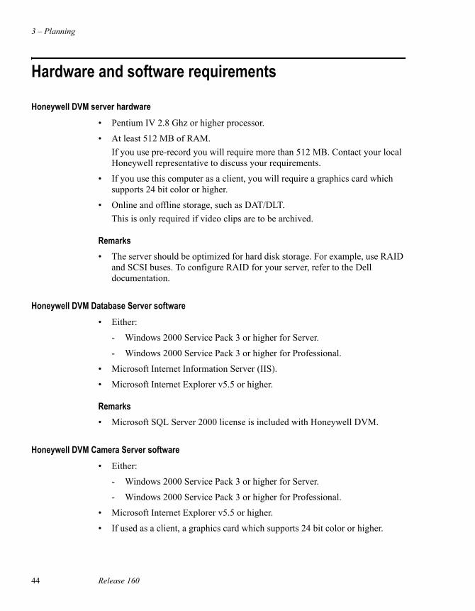
Honeywell DVM server hardware• Pentium IV 2.8 Ghz or higher processor.
• At least 512 MB of RAM.If you use pre-record you will require more than 512 MB. Contact your local Honeywell representative to discuss your requirements.
• If you use this computer as a client, you will require a graphics card which supports 24 bit color or higher.
• Online and offline storage, such as DAT/DLT.This is only required if video clips are to be archived.
Remarks• The server should be optimized for hard disk storage. For example, use RAID
and SCSI buses. To configure RAID for your server, refer to the Dell documentation.
Honeywell DVM Database Server software• Either:
- Windows 2000 Service Pack 3 or higher for Server.
- Windows 2000 Service Pack 3 or higher for Professional.
• Microsoft Internet Information Server (IIS).
• Microsoft Internet Explorer v5.5 or higher.
Remarks• Microsoft SQL Server 2000 license is included with Honeywell DVM.
Honeywell DVM Camera Server software• Either:
- Windows 2000 Service Pack 3 or higher for Server.
- Windows 2000 Service Pack 3 or higher for Professional.
• Microsoft Internet Explorer v5.5 or higher.
• If used as a client, a graphics card which supports 24 bit color or higher.
Hardware and software requirements
Honeywell Digital Video Manager User Guide 45
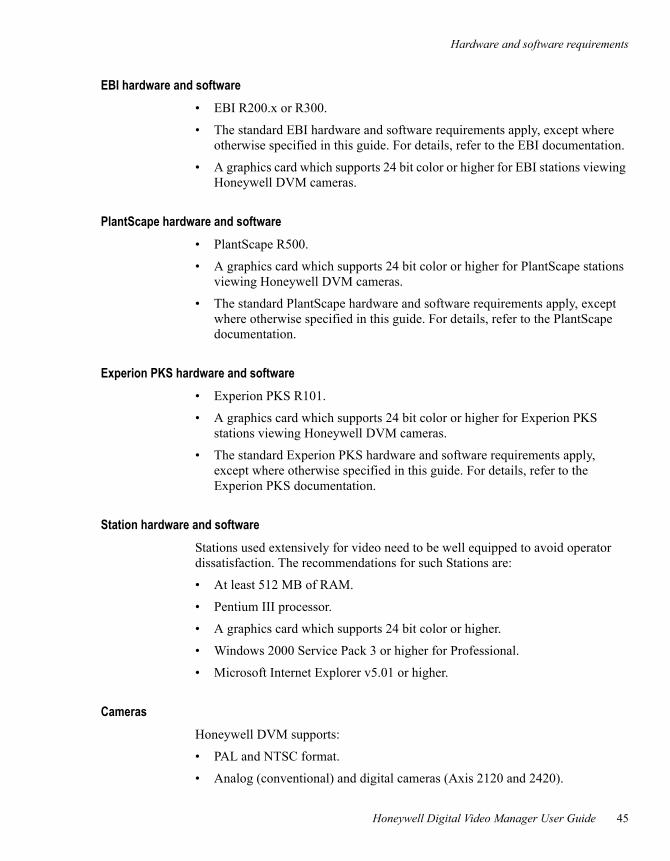
EBI hardware and software• EBI R200.x or R300.
• The standard EBI hardware and software requirements apply, except where otherwise specified in this guide. For details, refer to the EBI documentation.
• A graphics card which supports 24 bit color or higher for EBI stations viewing Honeywell DVM cameras.
PlantScape hardware and software• PlantScape R500.
• A graphics card which supports 24 bit color or higher for PlantScape stations viewing Honeywell DVM cameras.
• The standard PlantScape hardware and software requirements apply, except where otherwise specified in this guide. For details, refer to the PlantScape documentation.
Experion PKS hardware and software• Experion PKS R101.
• A graphics card which supports 24 bit color or higher for Experion PKS stations viewing Honeywell DVM cameras.
• The standard Experion PKS hardware and software requirements apply, except where otherwise specified in this guide. For details, refer to the Experion PKS documentation.
Station hardware and softwareStations used extensively for video need to be well equipped to avoid operator dissatisfaction. The recommendations for such Stations are:
• At least 512 MB of RAM.
• Pentium III processor.
• A graphics card which supports 24 bit color or higher.
• Windows 2000 Service Pack 3 or higher for Professional.
• Microsoft Internet Explorer v5.01 or higher.
CamerasHoneywell DVM supports:
• PAL and NTSC format.
• Analog (conventional) and digital cameras (Axis 2120 and 2420).
3 – Planning
46 Release 160
Camera streamersHoneywell DVM supports the following types of camera streamer:
• Axis Communications 2100
• Axis Communications 2110
• Axis Communications 2120
• Axis Communications 2130 (without preset support)
• Axis Communications 2400 1.x
• Axis Communications 2400 2.x
• Axis Communications 2400+ 3.01 (uses the Axis 2400 2.x setting)
• Axis Communications 2401 1.x
• Axis Communications 2401 2.x
• Axis Communications 2401+ 3.01 (uses the Axis 2401 2.x setting)
• Axis Communications 2420
• MegaChips OpennetView
• MegaChips MD-100
• CS100
Honeywell Digital Video Manager User Guide 47
4Installation and upgrade
This chapter describes how to upgrade or install the hardware and software components for Honeywell DVM R160.
Task Go to: Done?Upgrading from Honeywell DVM R150 to R160 page 48
Installing Honeywell DVM R160 page 51
4 – Installation and upgrade
48 Release 160
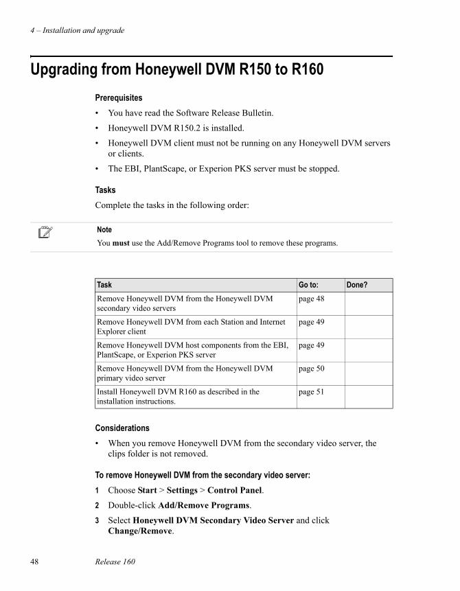
Upgrading from Honeywell DVM R150 to R160Prerequisites• You have read the Software Release Bulletin.
• Honeywell DVM R150.2 is installed.
• Honeywell DVM client must not be running on any Honeywell DVM servers or clients.
• The EBI, PlantScape, or Experion PKS server must be stopped.
TasksComplete the tasks in the following order:
Considerations• When you remove Honeywell DVM from the secondary video server, the
clips folder is not removed.
To remove Honeywell DVM from the secondary video server:1 Choose Start > Settings > Control Panel.
2 Double-click Add/Remove Programs.
3 Select Honeywell DVM Secondary Video Server and click Change/Remove.
NoteYou must use the Add/Remove Programs tool to remove these programs.
Task Go to: Done?Remove Honeywell DVM from the Honeywell DVM secondary video servers
page 48
Remove Honeywell DVM from each Station and Internet Explorer client
page 49
Remove Honeywell DVM host components from the EBI, PlantScape, or Experion PKS server
page 49
Remove Honeywell DVM from the Honeywell DVM primary video server
page 50
Install Honeywell DVM R160 as described in the installation instructions.
page 51
Upgrading from Honeywell DVM R150 to R160
Honeywell Digital Video Manager User Guide 49
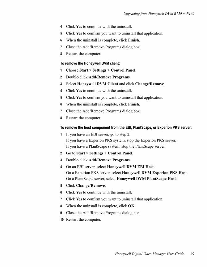
4 Click Yes to continue with the uninstall.
5 Click Yes to confirm you want to uninstall that application.
6 When the uninstall is complete, click Finish.
7 Close the Add/Remove Programs dialog box.
8 Restart the computer.
To remove the Honeywell DVM client:1 Choose Start > Settings > Control Panel.
2 Double-click Add/Remove Programs.
3 Select Honeywell DVM Client and click Change/Remove.
4 Click Yes to continue with the uninstall.
5 Click Yes to confirm you want to uninstall that application.
6 When the uninstall is complete, click Finish.
7 Close the Add/Remove Programs dialog box.
8 Restart the computer.
To remove the host component from the EBI, PlantScape, or Experion PKS server: 1 If you have an EBI server, go to step 2.
If you have a Experion PKS system, stop the Experion PKS server.If you have a PlantScape system, stop the PlantScape server.
2 Go to Start > Settings > Control Panel.
3 Double-click Add/Remove Programs.
4 On an EBI server, select Honeywell DVM EBI Host.On a Experion PKS server, select Honeywell DVM Experion PKS Host.On a PlantScape server, select Honeywell DVM PlantScape Host.
5 Click Change/Remove.
6 Click Yes to continue with the uninstall.
7 Click Yes to confirm you want to uninstall that application.
8 When the uninstall is complete, click OK.
9 Close the Add/Remove Programs dialog box.
10 Restart the computer.
4 – Installation and upgrade
50 Release 160
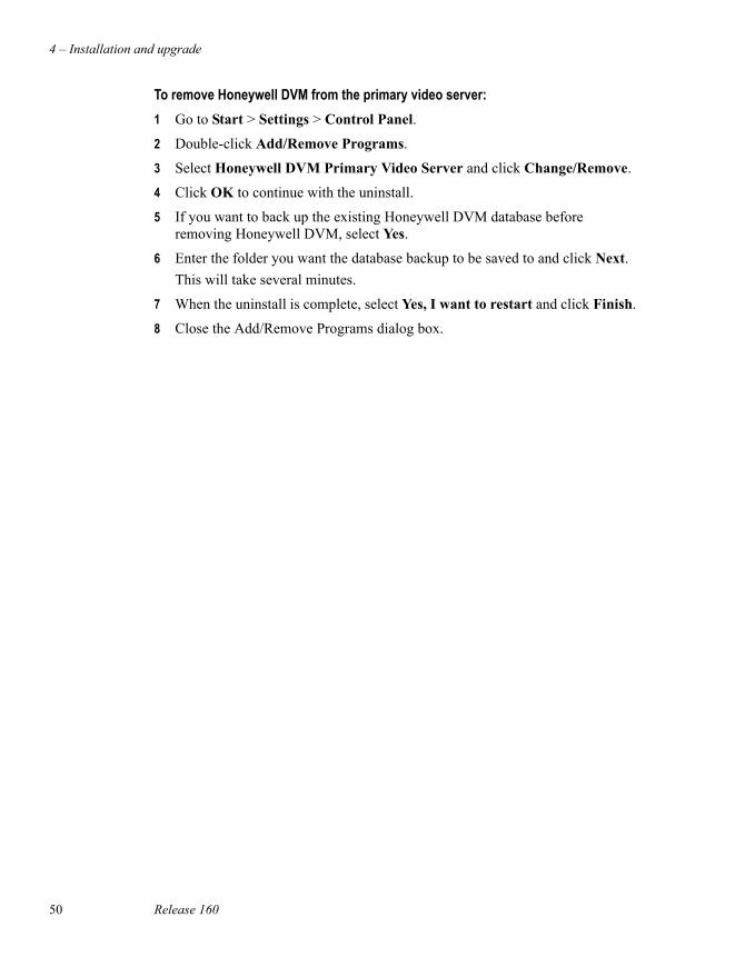
To remove Honeywell DVM from the primary video server:1 Go to Start > Settings > Control Panel.
2 Double-click Add/Remove Programs.
3 Select Honeywell DVM Primary Video Server and click Change/Remove.
4 Click OK to continue with the uninstall.
5 If you want to back up the existing Honeywell DVM database before removing Honeywell DVM, select Yes.
6 Enter the folder you want the database backup to be saved to and click Next.This will take several minutes.
7 When the uninstall is complete, select Yes, I want to restart and click Finish.
8 Close the Add/Remove Programs dialog box.
Installing Honeywell DVM R160
Honeywell Digital Video Manager User Guide 51
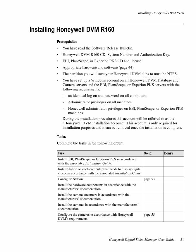
Installing Honeywell DVM R160Prerequisites• You have read the Software Release Bulletin.
• Honeywell DVM R160 CD, System Number and Authorization Key.
• EBI, PlantScape, or Experion PKS CD and license.
• Appropriate hardware and software (page 44).
• The partition you will save your Honeywell DVM clips to must be NTFS.
• You have set up a Windows account on all Honeywell DVM Database and Camera servers and the EBI, PlantScape, or Experion PKS servers with the following requirements:
- an identical log on and password on all computers
- Administrator privileges on all machines
- Honeywell administrator privileges on EBI, PlantScape, or Experion PKS machines.
During the installation procedures this account will be referred to as the “Honeywell DVM installation account”. This account is only required for installation purposes and it can be removed once the installation is complete.
TasksComplete the tasks in the following order:
Task Go to: Done?Install EBI, PlantScape, or Experion PKS in accordance with the associated Installation Guide.
Install Station on each computer that needs to display digital video, in accordance with the associated Installation Guide.
Configure Station page 53
Install the hardware components in accordance with the manufacturers’ documentation.
Install the camera streamers in accordance with the manufacturers’ documentation.
Install the cameras in accordance with the manufacturers’ documentation.
Configure the cameras in accordance with Honeywell DVM’s requirements.
page 55
4 – Installation and upgrade
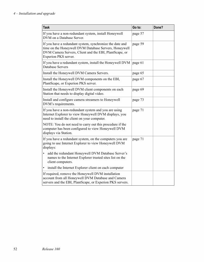
52 Release 160
If you have a non-redundant system, install Honeywell DVM on a Database Server.
page 57
If you have a redundant system, synchronize the date and time on the Honeywell DVM Database Servers, Honeywell DVM Camera Servers, Client and the EBI, PlantScape, or Experion PKS server.
page 59
If you have a redundant system, install the Honeywell DVM Database Servers
page 61
Install the Honeywell DVM Camera Servers. page 65
Install the Honeywell DVM components on the EBI, PlantScape, or Experion PKS server.
page 67
Install the Honeywell DVM client components on each Station that needs to display digital video.
page 69
Install and configure camera streamers to Honeywell DVM’s requirements.
page 73
If you have a non-redundant system and you are using Internet Explorer to view Honeywell DVM displays, you need to install the client on your computer.NOTE: You do not need to carry out this procedure if the computer has been configured to view Honeywell DVM displays via Station.
page 71
If you have a redundant system, on the computers you are going to use Internet Explorer to view Honeywell DVM displays:• add the redundant Honeywell DVM Database Server’s
names to the Internet Explorer trusted sites list on the client computers.
• install the Internet Explorer client on each computer
page 71
If required, remove the Honeywell DVM installation account from all Honeywell DVM Database and Camera servers and the EBI, PlantScape, or Experion PKS servers.
Task Go to: Done?
Configuring Station
Honeywell Digital Video Manager User Guide 53
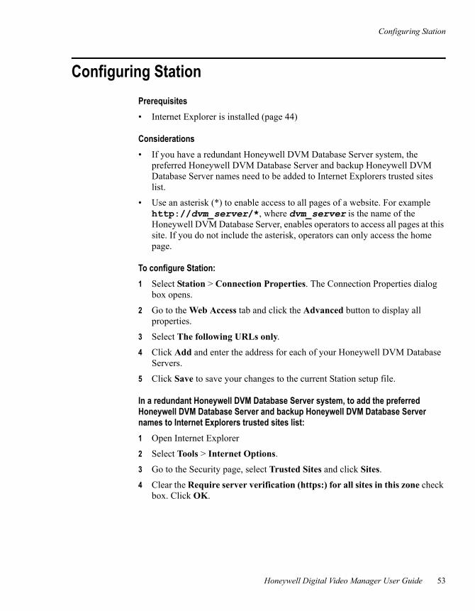
Configuring StationPrerequisites• Internet Explorer is installed (page 44)
Considerations• If you have a redundant Honeywell DVM Database Server system, the
preferred Honeywell DVM Database Server and backup Honeywell DVM Database Server names need to be added to Internet Explorers trusted sites list.
• Use an asterisk (*) to enable access to all pages of a website. For example http://dvm_server/*, where dvm_server is the name of the Honeywell DVM Database Server, enables operators to access all pages at this site. If you do not include the asterisk, operators can only access the home page.
To configure Station:1 Select Station > Connection Properties. The Connection Properties dialog
box opens.
2 Go to the Web Access tab and click the Advanced button to display all properties.
3 Select The following URLs only.
4 Click Add and enter the address for each of your Honeywell DVM Database Servers.
5 Click Save to save your changes to the current Station setup file.
In a redundant Honeywell DVM Database Server system, to add the preferred Honeywell DVM Database Server and backup Honeywell DVM Database Server names to Internet Explorers trusted sites list:1 Open Internet Explorer
2 Select Tools > Internet Options.
3 Go to the Security page, select Trusted Sites and click Sites.
4 Clear the Require server verification (https:) for all sites in this zone check box. Click OK.
4 – Installation and upgrade
54 Release 160
5 In the Add to this Web site to this zone: field, enter:
a. http://DVM_ServerA/* . Click Add.where DVM_ServerA is the name of the preferred Honeywell DVM Database Server.
b. http://DVM_ServerB/* . Click Add.where DVM_ServerB is the name of the backup Honeywell DVM Database Server.
6 Click OK to close the Trusted Sites dialog box.
7 Click OK to close the Internet Options dialog box.
8 Close Internet Explorer.
Configuring PTZ cameras
Honeywell Digital Video Manager User Guide 55
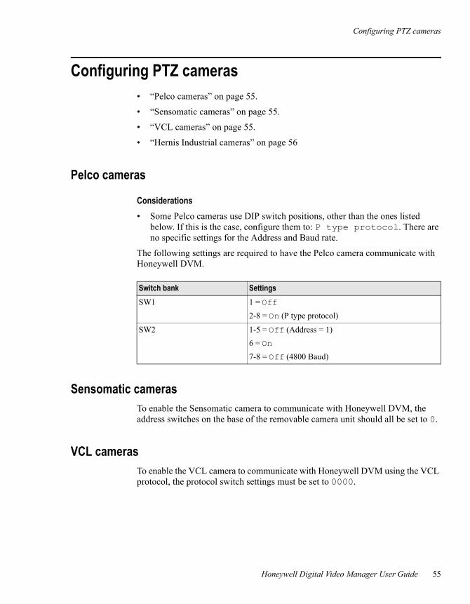
Configuring PTZ cameras• “Pelco cameras” on page 55.
• “Sensomatic cameras” on page 55.
• “VCL cameras” on page 55.
• “Hernis Industrial cameras” on page 56
Pelco cameras
Considerations• Some Pelco cameras use DIP switch positions, other than the ones listed
below. If this is the case, configure them to: P type protocol. There are no specific settings for the Address and Baud rate.
The following settings are required to have the Pelco camera communicate with Honeywell DVM.
Sensomatic camerasTo enable the Sensomatic camera to communicate with Honeywell DVM, the address switches on the base of the removable camera unit should all be set to 0.
VCL camerasTo enable the VCL camera to communicate with Honeywell DVM using the VCL protocol, the protocol switch settings must be set to 0000.
Switch bank SettingsSW1 1 = Off
2-8 = On (P type protocol)
SW2 1-5 = Off (Address = 1)6 = On7-8 = Off (4800 Baud)

4 – Installation and upgrade
56 Release 160
Hernis Industrial camerasTo enable the Hernis Industrial camera (www.hernis.com) to communicate with Honeywell DVM, the camera needs to be configured as a Pelco Dome (Pelco P protocol) on the Honeywell DVM Camera Definition page. No other software configuration is required.
Installing a non-redundant Honeywell DVM Database Server
Honeywell Digital Video Manager User Guide 57
Installing a non-redundant Honeywell DVM Database Server
Prerequisites• The server meets the hardware/software requirements (page 44).
• The log on and password for the Honeywell DVM installation account (page 51).
Considerations• A Honeywell DVM Database Server can also be installed with the Honeywell
DVM Camera Server.
• If SQL Server 2000 and SQL Server 2000 Service Pack 3 are not installed on your computer, during the installation you will be asked to reboot your computer for each of these installations. When your computer reboots, log on using the Honeywell DVM installation account and Honeywell DVM will continue the installation.
To install Honeywell DVM on a non-redundant Database Server:1 Log on using the Honeywell DVM installation account.
2 Insert the Honeywell DVM CD ROM into the computer. The “autorun” setup wizard starts. (If the wizard doesn’t start, open Windows Explorer, navigate to the Server folder on the CD ROM and double-click setup.exe.)
3 If requested, click restart to upgrade the version of Windows Installer.When the computer restarts, log on using the Honeywell DVM installation account.
4 When the Welcome screen appears, click Next.
5 Read the installation notes. Click Next.
6 Enter your name and your company name. Click Next.
NoteThis installation procedure is for a non-redundant Honeywell DVM system. To install a redundant Honeywell DVM system see, “Installing redundant Honeywell DVM Database Servers” on page 61.
4 – Installation and upgrade
58 Release 160
7 If you are only installing a Honeywell DVM Database Server, select Database Server.If you are installing a Honeywell DVM Database Server and a Honeywell DVM Camera Server, select Database Server and Camera Server.
8 Click Next.
9 Enter the Honeywell DVM System Number and Authorization Key from your Honeywell DVM software license. Click Next.
10 Select a folder for the Honeywell DVM software. Click Next.
11 If you are only installing a Honeywell DVM Database Server, go to step 12.If you are installing a Honeywell DVM Database Server and a Honeywell DVM Camera Server:
a. Select a folder where the video clips are to be stored. Click Next.
b. Select a folder where the video is to be archived. Click Next.
12 If Microsoft SQL Server 2000 is not already installed, select a folder to install the software. Click Next.
13 Enter and confirm the mngr password (this is the same password as the mngr account for the EBI, PlantScape, or Experion PKS server). Click Next.
14 Confirm the details. Click Next to begin the installation.
15 Agree to restart the computer and click Finish.
The installation of the Honeywell DVM Database Server is now complete.
Synchronizing the date and time on the servers
Honeywell Digital Video Manager User Guide 59
Synchronizing the date and time on the serversThe date and time on all servers need to be synchronized to ensure that all dates and/or times associated with events in the database are consistent between servers.
If you are using Honeywell DVM with EBI, PlantScape, or Experion PKS, it is recommended that the EBI, PlantScape, or Experion PKS server is used as the preferred time source and all other Honeywell DVM Database and Camera Servers are configured to synchronize with that server.
If you are not using Honeywell DVM with EBI, PlantScape, or Experion PKS, in a redundant server system, your preferred time source server can be the preferred Honeywell DVM Database Server, the backup Honeywell DVM Database Server or a network time source. Once your preferred time source has been selected, configure all Honeywell DVM Database and Camera Servers to synchronize with the preferred time source server.
To configure all other servers to synchronize with the preferred time source server, you need to set up a time service on the preferred time source server and then synchronize all other servers with the preferred time source server.
To set up a time service on the preferred time source:1 Select Start > Run and run settimesource.vbs, which is located in the
server\run folder. This program is silent if successful.
2 Select Start > Settings > Control Panel > Administrative Tools > Services.
3 Right-click Windows Time service and select Properties.
4 Set the startup type to Automatic.
5 If the Windows Time service is running, stop it.
6 Restart the Windows Time service.
Considerations• Before starting the Time Service, ensure that the EBI, PlantScape, or
Experion PKS server and all Honeywell DVM Database and Camera Servers are configured to be in the same time zone. The time zone setting can be checked by opening Date/Time in the Windows Control Panel.
NoteIf the Honeywell DVM Database Server is a member of a Windows 2000 domain then time synchronization is already configured. You do not need to complete this procedure.
4 – Installation and upgrade
60 Release 160
To synchronize the time on the other computers:1 On the other computers, open a Command Prompt window and type
net time /setsntp:preferredtimesource where preferredtimesource is the machine name of the preferred time source server.
2 Select Start > Settings > Control Panel > Administrative Tools > Services.
3 Right-click Windows Time service and select Properties.
4 Set the startup type to Automatic.
5 If the Windows Time service is running, stop it.
6 Restart the Windows Time service.
Re-synchronizing the date and time on the serversThe Time Service synchronizes the system time with the preferred time source server every hour.
If you change the time on the preferred time source server (or the preferred time source server is down for some period of time) and you want all other computers to synchronize immediately, you need to stop and restart the Time Service on each computer.
To re-synchronize the time: 1 Start > Setting > Control Panel.
2 Double-click Administrative Tools and open Services.
3 Stop and start the Windows Time service.
Installing redundant Honeywell DVM Database Servers
Honeywell Digital Video Manager User Guide 61
Installing redundant Honeywell DVM Database Servers
Redundancy is a configuration that allows a backup Honeywell DVM Database Server (the second server) to automatically continue the role of the preferred Honeywell DVM Database Server (master server) in the event of a hardware or software failure on the preferred Honeywell DVM Database Server.
The preferred Honeywell DVM Database Server is the server that is performing all the Honeywell DVM Database Server roles at a given time. A backup Honeywell DVM Database Server is idle, waiting to take over the master role if needed.
Prerequisites• Both servers meets the hardware/software requirements (page 44)
• The log on and password for the Honeywell DVM installation account (page 51)
• Honeywell DVM installation account log on and password must be set and exist on all Honeywell DVM Database Servers.
• mngr password for EBI, PlantScape, or Experion PKS server
• The backup Honeywell DVM Database Server must be able to ping the preferred Honeywell DVM Database Server by computer name.
Considerations• By default, the first Honeywell DVM Database Server of a redundant pair
installed becomes the preferred Honeywell DVM Database Server.
• Honeywell DVM Camera Servers can be installed on redundant Honeywell DVM Database Servers, however, it is not recommended if you have a large system with multiple Honeywell DVM Camera Servers. For large systems we recommend that you create standalone redundant Honeywell DVM Database Servers.
• If SQL Server 2000 and SQL Server 2000 Service Pack 3 are not installed on your computer, during the installation you will be asked to reboot your computer for each of these installations. When your computer reboots, log on using the Honeywell DVM installation account and Honeywell DVM will continue the installation.
NoteHoneywell DVM supports redundancy of the Honeywell DVM Database Servers only. Redundancy of Honeywell DVM Camera Servers is not supported.
4 – Installation and upgrade
62 Release 160
Installing the first Honeywell DVM Database Server of a redundant pair
Considerations• By default, once the installation is complete this machine will become the
preferred Honeywell DVM Database Server.
To install the first Honeywell DVM Database Server of a redundant pair:1 Log on using the Honeywell DVM installation account.
2 Insert the Honeywell DVM CD ROM into the computer. The “autorun” setup wizard starts. (If the wizard doesn’t start, open Windows Explorer, navigate to the Server folder on the CD ROM and double-click setup.exe.)
3 If requested, click restart to upgrade the version of Windows Installer.When the computer restarts, log on using the Honeywell DVM installation account.
4 When the Welcome screen appears, click Next.
5 Read the installation notes. Click Next.
6 Enter your name and your company name. Click Next.
7 If you are only installing a Honeywell DVM Database Server, select Database Server. If you want to install a Honeywell DVM Camera Server as well as a Honeywell DVM Database Server, select Database Server and Camera Server.
8 Click Next.
9 Enter the Honeywell DVM System Number and Authorization Key from your Honeywell DVM software license. Click Next.
10 Select I wish to install the first Database Server of a redundant pair.
11 Select a folder for the Honeywell DVM software. Click Next.
12 If you are only installing a Honeywell DVM Database Server, go to step 13.If you are installing a Honeywell DVM Database Server and a Honeywell DVM Camera Server:
a. Select a folder where the video clips are to be stored. Click Next.
b. Select a folder where the video is to be archived. Click Next.
13 If Microsoft SQL Server 2000 is not already installed, select a folder to install the software. Click Next.
14 Enter and confirm the mngr password (this is the same password as the mngr account for the EBI, PlantScape, or Experion PKS server). Click Next.
15 Confirm the details. Click Next to begin the installation.
Installing redundant Honeywell DVM Database Servers
Honeywell Digital Video Manager User Guide 63
16 If requested, agree to restart the computer and log on using the Honeywell DVM installation account.
17 When the Installation Wizard Complete screen appears, agree to restart the computer and click Finish.
The installation of the first Honeywell DVM Database Server of a redundant pair is now complete.
Creating a redundant pair with an existing Honeywell DVM Database Server
Prerequisites• The name of the existing Honeywell DVM Database Server.
• The existing Honeywell DVM Database Server can be contacted and SQL Server is running on it.
• The mngr password for the EBI, PlantScape, or Experion PKS server.
Considerations• If SQL Server 2000 and SQL Server 2000 Service Pack 3 are not installed on
your computer, during the installation you will be asked to reboot your computer for each of these installations. When your computer reboots, log on using the Honeywell DVM installation account and Honeywell DVM will continue the installation.
To create a redundant pair with an existing Honeywell DVM Database Server:1 Log on using the Honeywell DVM installation account.
2 Insert the Honeywell DVM CD ROM into the computer. The “autorun” setup wizard starts. (If the wizard doesn’t start, open Windows Explorer, navigate to the Server folder on the CD ROM and double-click setup.exe.)
3 If requested, click restart to upgrade the version of Windows Installer.When the computer restarts, log on using the Honeywell DVM installation account.
4 When the Welcome screen appears, click Next.
5 Read the installation notes. Click Next.
6 Enter your name and your company name. Click Next.
4 – Installation and upgrade
64 Release 160
7 If you are only installing a Honeywell DVM Database Server, select Database Server. If you are installing a Honeywell DVM Database Server and a Honeywell DVM Camera Server, select Database Server and Camera Server.
8 Click Next.
9 Enter the Honeywell DVM System Number and Authorization Key from your Honeywell DVM software license. Click Next.
10 Select I wish to create a redundant pair with an existing Database Server. Click Next.
11 Enter the computer name of the existing Honeywell DVM Database Server computer. Click Next.
12 Select a folder for the Honeywell DVM software. Click Next.
13 If Microsoft SQL Server 2000 is not already installed, select a folder to install the software. Click Next.
14 Enter and confirm the mngr password (this is the same password as the mngr account for the EBI, PlantScape, or Experion PKS server). Click Next.
15 Confirm the details. Click Next to begin the installation.
16 If requested, agree to restart the computer and log on using the Honeywell DVM installation account.
17 When the Installation Wizard Complete screen appears, agree to restart the computer and click Finish. The installation of the backup Honeywell DVM Database Server is now complete.
18 Restart the existing Honeywell DVM Database Server.
19 Restart Event Activation on your EBI, PlantScape, or Experion PKS computers. For more information, see the Configuration Guide for your system.
Installing a Honeywell DVM Camera Server
Honeywell Digital Video Manager User Guide 65
Installing a Honeywell DVM Camera ServerPrerequisites• The server meets the hardware/software requirements (page 44)
• The log on and password for the Honeywell DVM installation account (page 51)
• Honeywell DVM has been installed on the Database Server (page 57) and is running
• In a redundant Database Server system, the name of the preferred Honeywell DVM Database Server
• Honeywell DVM Camera Server must be able to ping the Honeywell DVM Database Server by computer name
To install Honeywell DVM:1 Log on using the Honeywell DVM installation account.
2 Insert the Honeywell DVM CD ROM into the computer. The “auto run” setup wizard starts. (If the wizard doesn’t start, open Windows Explorer and double click setup.exe on the CD ROM.)
3 If requested, click restart to upgrade the version of Windows Installer.When the computer restarts, log on using the Honeywell DVM installation account.
4 When the Welcome screen appears, click Next.
5 Read the installation notes. Click Next.
6 Enter your name and your company name. Click Next.
7 Select Camera Server. Click Next.
8 Select a folder for the Honeywell DVM software. Click Next.
9 Select a folder where the video clips are to be stored. Click Next.
10 Select a folder where the video is to be archived. Click Next.
11 Enter and confirm the mngr password (this is the same password as the mngr account for the EBI, PlantScape, or Experion PKS server). Click Next.
12 Enter the name of the Honeywell DVM Database Server. Click Next.In a redundant Database Server system, this is the name of the preferred Honeywell DVM Database Server.

4 – Installation and upgrade
66 Release 160
13 Confirm the details. Click Next to begin the installation.
14 Agree to restart the computer if requested.
The installation of the Honeywell DVM Camera Server is now complete.
Installing Honeywell DVM Host components on the EBI, PlantScape, or Experion PKS server
Honeywell Digital Video Manager User Guide 67
Installing Honeywell DVM Host components on the EBI, PlantScape, or Experion PKS server
This procedure installs the required Honeywell DVM components on the EBI, PlantScape, or Experion PKS server to allow:
• Honeywell DVM system alarms to be sent to EBI, PlantScape, or Experion PKS
• EBI, PlantScape, or Experion PKS alarm/event activation of recordings
Prerequisites• The log on and password for the Honeywell DVM installation account
(page 51)
• mngr account and password
• Honeywell DVM has been installed on the Database Server (page 57).
• EBI, PlantScape, or Experion PKS has been installed.
• Honeywell DVM Database Server computer name. (In a redundant system, the name of the preferred Honeywell DVM Database Server.)This is required so that Stations can access the SQL Server data on the Honeywell DVM Database Server.
• EBI, PlantScape, or Experion PKS server must be able to ping the Honeywell DVM Database Server (in a redundant system, the preferred Honeywell DVM Database Server) by computer name.
• EBI, PlantScape, or Experion PKS is running.
• The Honeywell DVM client is not already installed.
Considerations• When you look up the name of the Honeywell DVM Database Server it will
end with a full stop. This full stop is not part of the computer name and should not be entered as part of the computer name in these procedures.
• To enable alarms to be sent to the EBI, PlantScape, or Experion PKS server after installing the Honeywell DVM host components, you must restart the DVM Camera Service on all Honeywell DVM Database and Camera Servers.
• If your EBI, PlantScape, or Experion PKS servers are part of a redundant pair, you need to install the host components on both of the servers.
4 – Installation and upgrade
68 Release 160
To install the EBI, PlantScape, or Experion PKS server host components:1 Log on using the Honeywell DVM installation account.
2 Ensure that EBI, PlantScape, or Experion PKS is running.
3 Insert the Honeywell DVM CD ROM into the computer. The “auto run” setup wizard starts. (If the wizard doesn’t start, open Windows Explorer and double click setup.exe on the CD ROM.)
4 If requested, click restart to upgrade the version of Windows Installer.When the computer restarts, log on using the Honeywell DVM installation account.
5 When the Welcome screen appears, click Next.
6 Read the installation notes. Click Next.
7 Enter your name and your company name. Click Next.
8 Select Host Components and click Next.
9 Enter and confirm the Windows mngr account password used by EBI, PlantScape, or Experion PKS. Click Next.
10 Enter the computer name of the Honeywell DVM Database Server. (In a redundant system enter the name of the preferred Honeywell DVM Database Server.) Click Next.This is required so that Stations can access the SQL Server data on the Honeywell DVM Database Server.
11 Confirm the installation details. Click Next to begin the installation.
12 Click Finish.
The installation of the host component is now complete.
Installing Honeywell DVM Client components on a Station computer
Honeywell Digital Video Manager User Guide 69
Installing Honeywell DVM Client components on a Station computer
This procedure installs the required Honeywell DVM components on Station computers so that users can view video.
You must perform this procedure for each Station that needs to view video.
Prerequisites• Operator-based or station-based security is enabled. For more information,
refer to the EBI, PlantScape, or Experion PKS Configuration Guide.
• Honeywell DVM has been installed on the Database Server (page 57).
• Honeywell DVM host components have been installed on the EBI, PlantScape, or Experion PKS server.
• The Windows user logged into Station has the appropriate security permissions. For more information, see “Security” on page 158.
• Station computers must be able to ping all Honeywell DVM Database and Camera Servers by their computer name.
• Station and your display have been configured (page 53).
Considerations• If you have a redundant system, the preferred Honeywell DVM Database
Server and backup Honeywell DVM Database Server names must be listed in the Internet Explorer trusted sites list.
To install the Station components:1 Log on as Windows Administrator.
2 Log on to Station with mngr security level.
3 Click the button to call up the System Menu.
4 Click the Honeywell Digital Video Manager icon. The Station connects to the Honeywell DVM system.In EBI, the Honeywell Digital Video Manager icon appears under Access Control and Security.In PlantScape and Experion PKS, the Honeywell Digital Video Manager icon appears under Options.
5 If requested, agree to trust information from Honeywell.
6 The Digital Video Client setup screen appears. Click Next.
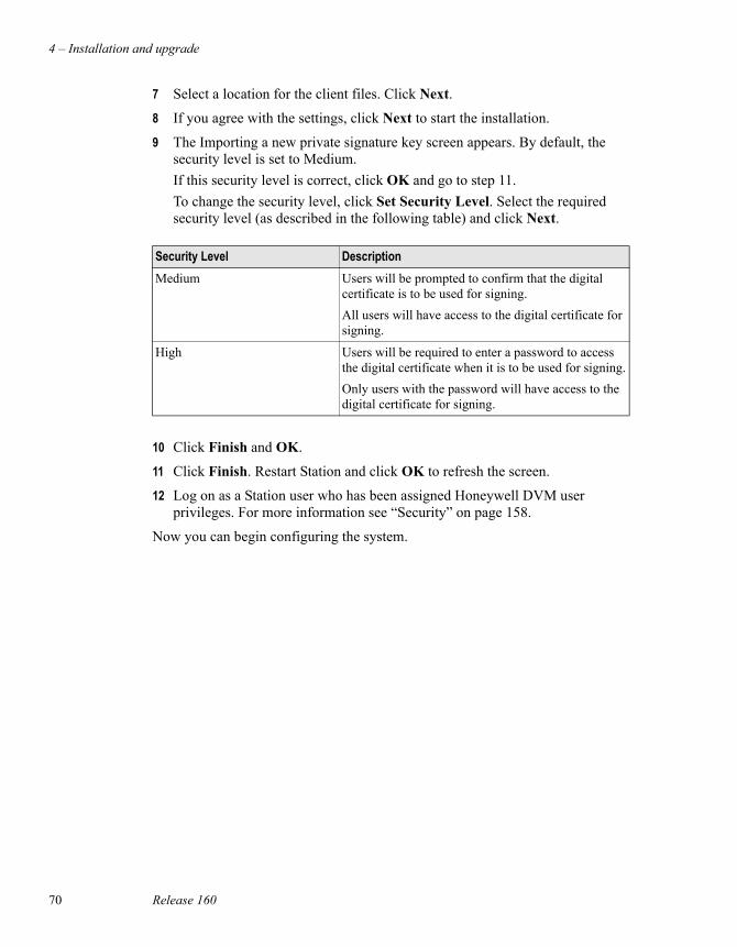
4 – Installation and upgrade
70 Release 160
7 Select a location for the client files. Click Next.
8 If you agree with the settings, click Next to start the installation.
9 The Importing a new private signature key screen appears. By default, the security level is set to Medium. If this security level is correct, click OK and go to step 11.To change the security level, click Set Security Level. Select the required security level (as described in the following table) and click Next.
10 Click Finish and OK.
11 Click Finish. Restart Station and click OK to refresh the screen.
12 Log on as a Station user who has been assigned Honeywell DVM user privileges. For more information see “Security” on page 158.
Now you can begin configuring the system.
Security Level DescriptionMedium Users will be prompted to confirm that the digital
certificate is to be used for signing.All users will have access to the digital certificate for signing.
High Users will be required to enter a password to access the digital certificate when it is to be used for signing.Only users with the password will have access to the digital certificate for signing.
Installing the Honeywell DVM client for Internet Explorer
Honeywell Digital Video Manager User Guide 71
Installing the Honeywell DVM client for Internet ExplorerThis procedure installs the required Honeywell DVM components on computers which will use Internet Explorer to view video.
Prerequisites• The computer meets the software requirements (page 44).
• You have a Honeywell DVM licence for each client.
• The user has the appropriate security permissions. For more information, see “Security” on page 158.
• Client computers must be able to ping all Honeywell DVM Database and Camera Servers by their computer name.
Considerations• If you have a redundant system, the preferred Honeywell DVM Database
Server and backup Honeywell DVM Database Servers names must be listed in the Internet Explorer trusted sites list. For more information, see “In a redundant system, to add the preferred Honeywell DVM Database Server and the backup Honeywell DVM Database Server names to Internet Explorers trusted sites list:” on page 71
In a redundant system, to add the preferred Honeywell DVM Database Server and the backup Honeywell DVM Database Server names to Internet Explorers trusted sites list:1 Open Internet Explorer.
2 Select Tools > Internet Options.
3 Go to the Security page, select Trusted Sites and click Sites.
4 Clear the Require server verification (https:) for all sites in this zone check box.
5 In the Add to this Web site to this zone: field, enter:
a. http://ServerA . Click Add.where ServerA is the name of the preferred Honeywell DVM Database Server.
NoteYou do not need to carry out this procedure if the computer has been configured to view Honeywell DVM displays via Station.
4 – Installation and upgrade
72 Release 160
b. http://ServerB . Click Add.where ServerB is the name of the backup Honeywell DVM Database Server.
c. Click OK.
6 Click OK to close the Internet Options dialog box.
To install the Internet Explorer components:1 Log on to your computer as Windows Administrator.
2 Start Internet Explorer and enter the URL http://machinename/DVM Where machinename is the name of the Honeywell DVM Database Server (in a redundant server system, the name of the preferred Honeywell DVM Database Server).
3 Agree to trust information from Honeywell.
4 The Digital Video Client setup screen appears. Click Next.
5 Select a location for the client files. Click Next.
6 If you agree with the current setting, click Next to start the installation.
7 The Importing a new private signature key screen appears. By default, the security level is set to Medium. If this security level is correct click OK and go to step 9. To change the security level, click Set Security Level. Select the required security level (as described in the following table) and click Next.
8 Click Finish and OK.
9 Click Finish and agree to restart your system if requested.
The installation of the Internet Explorer client is now complete.
Security Level DescriptionMedium Users will be prompted to confirm that the digital
certificate is to be used for signing.All users will have access to the digital certificate for signing.
High Users will be required to enter a password to access the digital certificate when it is to be used for signing.Only users with the password will have access to the digital certificate for signing.
Installing and configuring camera streamers
Honeywell Digital Video Manager User Guide 73
Installing and configuring camera streamers
This section only contains installation and configuration information that is specific to Honeywell DVM. For detailed information about installing a particular camera streamer, refer to the manufacturer’s documentation.
NoteThe Axis documentation, refers to the Axis 2100, 2120, 2400, 2401 and 2420 as camera servers. In the Honeywell DVM documentation these are referred to as camera streamers.
To install and configure: Go to:Axis 2100 page 74
Axis 2120 page 74
Axis 2400 x.x page 75
Axis 2401 x.x page 75
Axis 2420 page 74
OpennetView page 79
MegaChips MD-100 page 82
CamStation CS100 page 83
4 – Installation and upgrade
74 Release 160
Axis 2100, 2120 and 2420
Considerations• Use the Axis-supplied tools to configure the streamer.
• Test the video viewing capability of the streamer using the Axis web pages before connecting to Honeywell DVM.
• There are no Honeywell DVM-specific setup instructions required for fixed camera operation.
• Configuring the Axis through the Axis web pages often requires a user name and password, these are set by Axis and are often root and pass, respectively.To change the user name and password, refer to the Axis documentation for your streamer. If you change the user name and password on the Axis web page, you must set the new user name and password in the Honeywell DVM Database Server. For more information, see “To set the new Axis user name and password in the Honeywell DVM Database Server” on page 74.
To set the new Axis user name and password in the Honeywell DVM Database Server 1 On the Honeywell DVM Database Server, select Start > Programs >
Microsoft SQL Server > Enterprise Manager.
2 In the Console Tree, double-click Microsoft SQL Servers > SQL Server Group.
3 Double-click the name of the Honeywell DVM Database Server > Databases > DVM > Tables.
4 Right-click tblCamera > Open Table > Return All Rows.
5 In the StreamerUsername field for the camera, enter the user name that you entered on the Axis web page.
6 In the StreamerPassword field for the camera, enter the password that you entered on the Axis web page.
Installing and configuring camera streamers
Honeywell Digital Video Manager User Guide 75
Axis 2400 x.x and Axis 2401 x.x
Considerations• Use the Axis-supplied tools to configure the streamer.
• Test the video viewing capability of the streamer using the Axis web pages before connecting to Honeywell DVM.
• There are no Honeywell DVM-specific setup instructions required for fixed camera operation.
• There are no specific baud rates.
• Configuring the Axis through the Axis web pages often requires a user name and password, these are set by Axis and are often root and pass, respectively.To change the user name and password, refer to the Axis documentation for your streamer. If you change the user name and password on the Axis web page, you must set the new user name and password in the Honeywell DVM Database Server. For more information, see “To set the new Axis user name and password in the Honeywell DVM Database Server” on page 75.
• For optimum PTZ performance for Pelco and Sensormatic cameras, wire them for duplex communication.
To set the new Axis user name and password in the Honeywell DVM Database Server1 On the Honeywell DVM Database Server, select Start > Programs >
Microsoft SQL Server > Enterprise Manager.
2 In the Console Tree, double-click Microsoft SQL Servers > SQL Server Group.
3 Double-click the name of the Honeywell DVM Database Server > Databases > DVM > Tables.
4 Right-click tblCamera > Open Table > Return All Rows.
5 In the StreamerUsername field for the camera, enter the user name that you entered on the Axis web page.
6 In the StreamerPassword field for the camera, enter the password that you entered on the Axis web page.
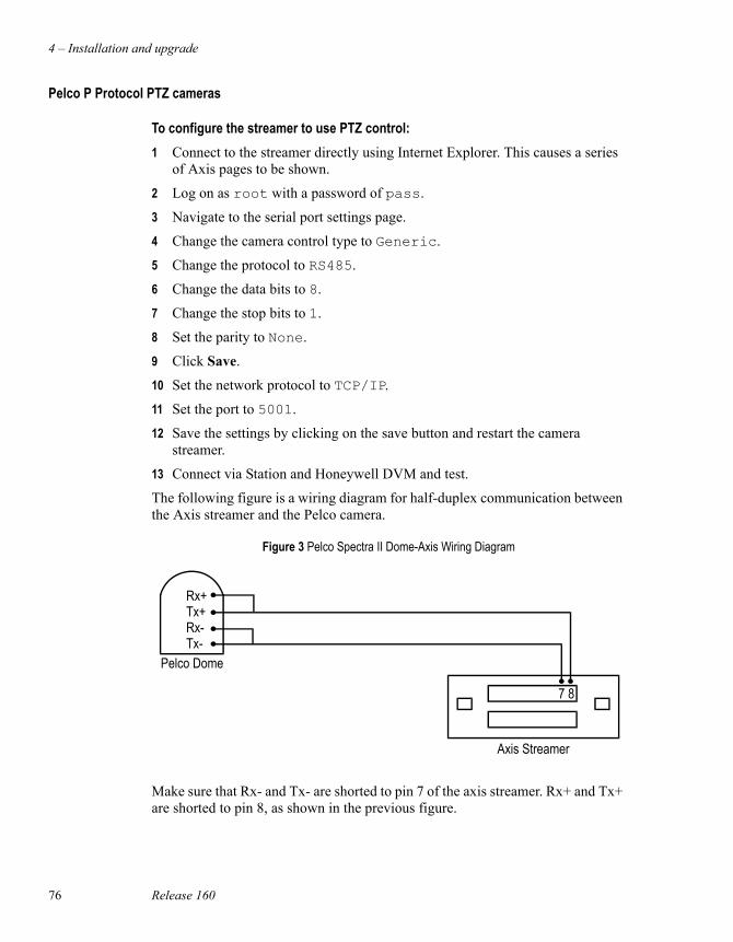
4 – Installation and upgrade
76 Release 160
Pelco P Protocol PTZ cameras
To configure the streamer to use PTZ control:1 Connect to the streamer directly using Internet Explorer. This causes a series
of Axis pages to be shown.
2 Log on as root with a password of pass.
3 Navigate to the serial port settings page.
4 Change the camera control type to Generic.
5 Change the protocol to RS485.
6 Change the data bits to 8.
7 Change the stop bits to 1.
8 Set the parity to None.
9 Click Save.
10 Set the network protocol to TCP/IP.
11 Set the port to 5001.
12 Save the settings by clicking on the save button and restart the camera streamer.
13 Connect via Station and Honeywell DVM and test.
The following figure is a wiring diagram for half-duplex communication between the Axis streamer and the Pelco camera.
Make sure that Rx- and Tx- are shorted to pin 7 of the axis streamer. Rx+ and Tx+ are shorted to pin 8, as shown in the previous figure.
Figure 3 Pelco Spectra II Dome-Axis Wiring Diagram
7 8
Rx+Tx+Rx-Tx-
Pelco Dome
Axis Streamer
Installing and configuring camera streamers
Honeywell Digital Video Manager User Guide 77
After performing the above procedure, you will not be able to control the camera using the Axis web pages because Axis and Honeywell DVM uses a different mechanism for camera control.
Sensomatic PTZ cameras
To configure the streamer to use PTZ control:1 Connect to the streamer directly using Internet Explorer. This causes a series
of Axis pages to be shown.
2 Log on as root with a password of pass.
3 Navigate to the serial port settings page.
4 Change the camera control type to Generic.
5 Change the protocol to RS485.
6 Change the data bits to 8.
7 Change the stop bits to 1.
8 Set the parity to None.
9 Click Save.
10 Set the network protocol to TCP/IP.
11 Set the port to 5001.
12 Save the settings and restart the camera streamer.
13 Connect via Station and Honeywell DVM and test.
After performing the above procedure, you will not be able to control the camera using the Axis web pages because Axis camera control of Sensomatic PTZ cameras is not natively supported by Axis web pages.
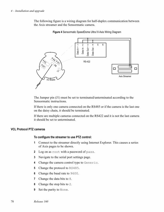
4 – Installation and upgrade
78 Release 160
The following figure is a wiring diagram for half-duplex communication between the Axis streamer and the Sensormatic camera.
The Jumper pin (J1) must be set to terminated/unterminated according to the Sensormatic instructions.
If there is only one camera connected on the RS485 or if the camera is the last one on the daisy chain, it should be terminated.
If there are multiple cameras connected on the RS422 and it is not the last camera it should be set to unterminated.
VCL Protocol PTZ cameras
To configure the streamer to use PTZ control:1 Connect to the streamer directly using Internet Explorer. This causes a series
of Axis pages to be shown.
2 Log on as root with a password of pass.
3 Navigate to the serial port settings page.
4 Change the camera control type to Generic.
5 Change the protocol to RS485.
6 Change the baud rate to 9600.
7 Change the data bits to 8.
8 Change the stop bits to 2.
9 Set the parity to None.
Figure 4 Sensormatic SpeedDome Ultra IV-Axis Wiring Diagram
RS-422
1 2 3 4 5 6
Data
In +
Data
In -
Data
Out +
Data
Out -
P7
P3P8
J1
I/O Board
7 8
Axis Streamer
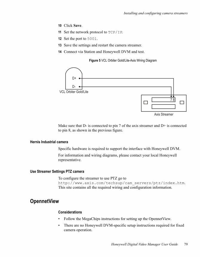
Installing and configuring camera streamers
Honeywell Digital Video Manager User Guide 79
10 Click Save.
11 Set the network protocol to TCP/IP.
12 Set the port to 5001.
13 Save the settings and restart the camera streamer.
14 Connect via Station and Honeywell DVM and test.
Make sure that D- is connected to pin 7 of the axis streamer and D+ is connected to pin 8, as shown in the previous figure.
Hernis Industrial cameraSpecific hardware is required to support the interface with Honeywell DVM.
For information and wiring diagrams, please contact your local Honeywell representative.
Use Streamer Settings PTZ cameraTo configure the streamer to use PTZ go to http://www.axis.com/techsup/cam_servers/ptz/index.htm. This site contains all the required wiring and configuration information.
OpennetView
Considerations• Follow the MegaChips instructions for setting up the OpennetView.
• There are no Honeywell DVM-specific setup instructions required for fixed camera operation.
Figure 5 VCL Orbiter Gold/Lite-Axis Wiring Diagram
7 8
D+
D-VCL Orbiter Gold/Lite
Axis Streamer
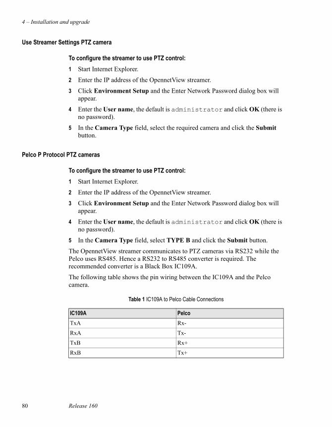
4 – Installation and upgrade
80 Release 160
Use Streamer Settings PTZ camera
To configure the streamer to use PTZ control:1 Start Internet Explorer.
2 Enter the IP address of the OpennetView streamer.
3 Click Environment Setup and the Enter Network Password dialog box will appear.
4 Enter the User name, the default is administrator and click OK (there is no password).
5 In the Camera Type field, select the required camera and click the Submit button.
Pelco P Protocol PTZ cameras
To configure the streamer to use PTZ control:1 Start Internet Explorer.
2 Enter the IP address of the OpennetView streamer.
3 Click Environment Setup and the Enter Network Password dialog box will appear.
4 Enter the User name, the default is administrator and click OK (there is no password).
5 In the Camera Type field, select TYPE B and click the Submit button.
The OpennetView streamer communicates to PTZ cameras via RS232 while the Pelco uses RS485. Hence a RS232 to RS485 converter is required. The recommended converter is a Black Box IC109A.
The following table shows the pin wiring between the IC109A and the Pelco camera.
Table 1 IC109A to Pelco Cable Connections
IC109A PelcoTxA Rx-
RxA Tx-
TxB Rx+
RxB Tx+
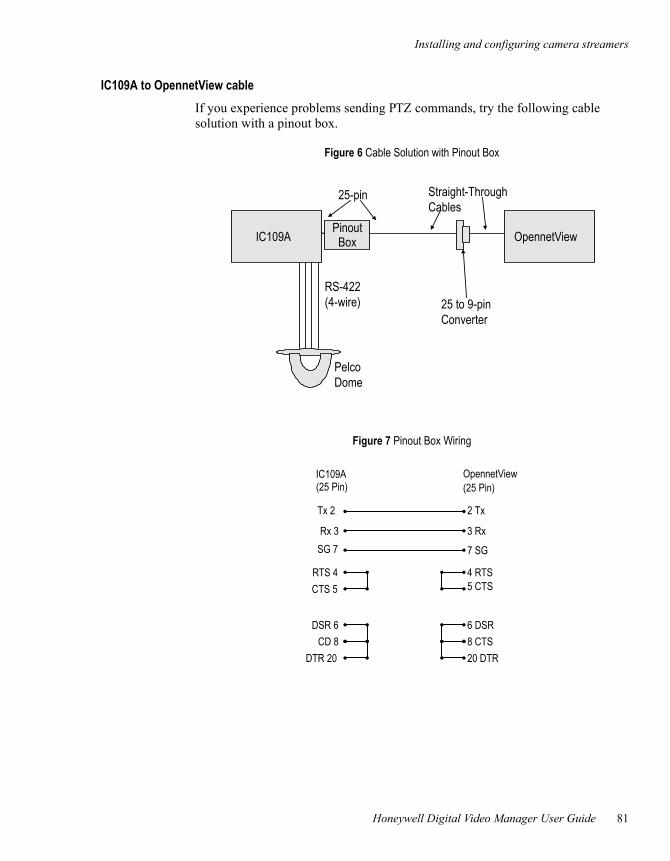
Installing and configuring camera streamers
Honeywell Digital Video Manager User Guide 81
IC109A to OpennetView cableIf you experience problems sending PTZ commands, try the following cable solution with a pinout box.
Figure 6 Cable Solution with Pinout Box
OpennetViewIC109APinoutBox
25-pin
25 to 9-pinConverter
Straight-ThroughCables
PelcoDome
RS-422(4-wire)
Figure 7 Pinout Box Wiring
(25 Pin) (25 Pin)
Tx 2 2 Tx
Rx 3 3 RxSG 7 7 SG
RTS 4CTS 5
DSR 6CD 8
DTR 20 20 DTR8 CTS6 DSR
5 CTS4 RTS
IC109A OpennetView
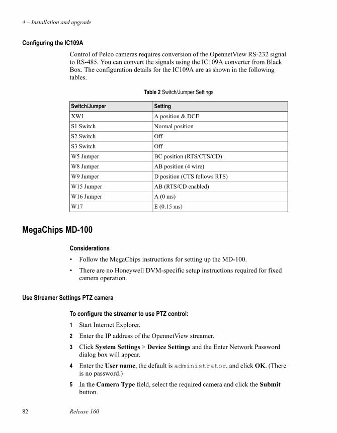
4 – Installation and upgrade
82 Release 160
Configuring the IC109AControl of Pelco cameras requires conversion of the OpennetView RS-232 signal to RS-485. You can convert the signals using the IC109A converter from Black Box. The configuration details for the IC109A are as shown in the following tables.
MegaChips MD-100
Considerations• Follow the MegaChips instructions for setting up the MD-100.
• There are no Honeywell DVM-specific setup instructions required for fixed camera operation.
Use Streamer Settings PTZ camera
To configure the streamer to use PTZ control:1 Start Internet Explorer.
2 Enter the IP address of the OpennetView streamer.
3 Click System Settings > Device Settings and the Enter Network Password dialog box will appear.
4 Enter the User name, the default is administrator, and click OK. (There is no password.)
5 In the Camera Type field, select the required camera and click the Submit button.
Table 2 Switch/Jumper Settings
Switch/Jumper SettingXW1 A position & DCE
S1 Switch Normal position
S2 Switch Off
S3 Switch Off
W5 Jumper BC position (RTS/CTS/CD)
W8 Jumper AB position (4 wire)
W9 Jumper D position (CTS follows RTS)
W15 Jumper AB (RTS/CD enabled)
W16 Jumper A (0 ms)
W17 E (0.15 ms)
Installing and configuring camera streamers
Honeywell Digital Video Manager User Guide 83
Pelco P Protocol PTZ cameras
To configure the streamer to use PTZ control:1 Start Internet Explorer.
2 Enter the IP address of the OpennetView streamer.
3 Click System Settings > Device Settings and the Enter Network Password dialog box will appear.
4 Enter the User name, the default is administrator, and click OK. (There is no password.)
5 In the Camera Type field, select TYPE B and click the Submit button.
CamStation CS100
Prerequisites• Setup the IP address of the CamStation CS100 device, using the CamStation
CS100 software supplied with the device. For more information, see the CamStation CS100 User Manual.
Considerations• No Honeywell DVM-specific setup operations are required on the CamStation
CS100 device unless you are using camera control. Defining camera control is done when you add and configure the cameras.For more information, see “Camera Control” on page 95.
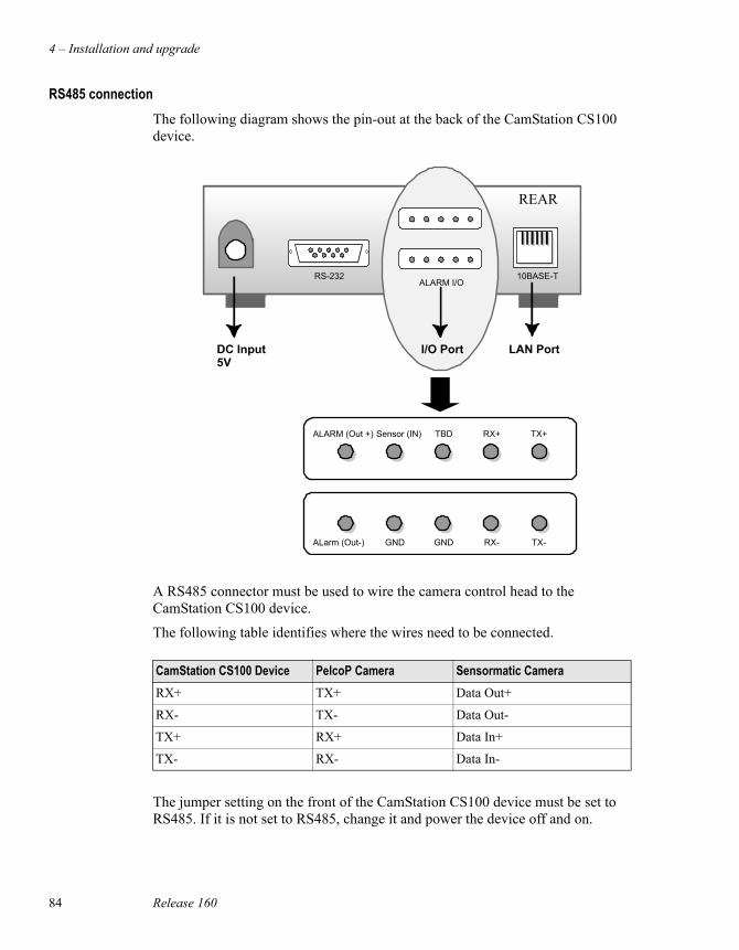
4 – Installation and upgrade
84 Release 160
RS485 connectionThe following diagram shows the pin-out at the back of the CamStation CS100 device.
A RS485 connector must be used to wire the camera control head to the CamStation CS100 device.
The following table identifies where the wires need to be connected.
The jumper setting on the front of the CamStation CS100 device must be set to RS485. If it is not set to RS485, change it and power the device off and on.
RS-232 10BASE-TALARM I/O
ALarm (Out-) GND GND TX-
ALARM (Out +) Sensor (IN) TBD RX+
RX-
TX+
LAN PortI/O PortDC Input5V
REAR
CamStation CS100 Device PelcoP Camera Sensormatic CameraRX+ TX+ Data Out+
RX- TX- Data Out-
TX+ RX+ Data In+
TX- RX- Data In-
Installing and configuring camera streamers
Honeywell Digital Video Manager User Guide 85
To check if the device has been wired correctly, use the CamStation CS100 software to see if the video is streaming and can be viewed. If it is, the wiring is correct.
Pelco P or Sensormatic
Considerations• When you configure the Camera Control settings, you must define the
Camera Control Type as either Pelco Dome or Sensormatic.
To configure the Pelco P or Sensormatic:1 Select Start > Run to open the Run dialog box.
2 Type telnet a.b.c.d and click OK, where a.b.c.d is the IP address of the CamStation CS100 device.
3 At the login: prompt, type CamStation and press <Enter>.
4 At the Password: prompt, type CamStation and press <Enter>.
5 At the CamStation> prompt, type set generic and press <Enter>.
6 Select the same baud rate setting which is configured on the camera head and press <Enter>.
7 Do not change the default printing mode. Press <Enter>.
8 Select the honeywell PTZ Control Mode setting and press <Enter>.
9 For the Generic PTZ Port Number, type 5001 and press <Enter>.
10 When you have finished, type exit to end the Telnet session.
Example Following is an example of what the telnet session could look like.CamStation> set generic
The command of this field is only for honewell company.
Baud Rate Setting
Current Baud Rate : 4800
Choose Baud Rate(1.2400, 2.4800, 3.9600, 4.19200, 5.38400) : 2
Printing Mode Setting.
Current Printing Mode : printing
Choose printing mode(1.printing, 2.no printing):
PTZ Control Mode Setting.
Current PTZ Control: sjcnc ptz
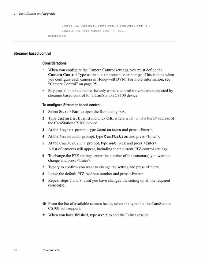
4 – Installation and upgrade
86 Release 160
Choose PTZ Control(1.sjcnc ptz, 2.honeywell ptz) : 2
Generic PTZ Port Number[5001] : 5001
CamStation>
Streamer based control
Considerations• When you configure the Camera Control settings, you must define the
Camera Control Type as Use streamer settings. This is done when you configure each camera in Honeywell DVM. For more information, see “Camera Control” on page 95.
• Step pan, tilt and zoom are the only camera control movements supported by streamer based control for a CamStation CS100 device.
To configure Streamer based control:1 Select Start > Run to open the Run dialog box.
2 Type telnet a.b.c.d and click OK, where a.b.c.d is the IP address of the CamStation CS100 device.
3 At the login: prompt, type CamStation and press <Enter>.
4 At the Password: prompt, type CamStation and press <Enter>.
5 At the CamStation> prompt, type set ptz and press <Enter>.A list of cameras will appear, including their current PTZ control settings.
6 To change the PTZ settings, enter the number of the camera(s) you want to change and press <Enter>.
7 Type y to confirm you want to change the setting and press <Enter>.
8 Leave the default PTZ Address number and press <Enter>.
9 Repeat steps 7 and 8, until you have changed the setting on all the required camera(s).
10 From the list of available camera heads, select the type that the CamStation CS100 will support.
11 When you have finished, type exit to end the Telnet session.
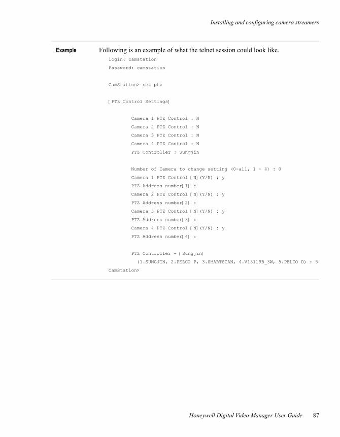
Installing and configuring camera streamers
Honeywell Digital Video Manager User Guide 87
Example Following is an example of what the telnet session could look like.login: camstation
Password: camstation
CamStation> set ptz
[PTZ Control Settings]
Camera 1 PTZ Control : N
Camera 2 PTZ Control : N
Camera 3 PTZ Control : N
Camera 4 PTZ Control : N
PTZ Controller : Sungjin
Number of Camera to change setting (0-all, 1 - 4) : 0
Camera 1 PTZ Control [N](Y/N) : y
PTZ Address number[1] :
Camera 2 PTZ Control [N](Y/N) : y
PTZ Address number[2] :
Camera 3 PTZ Control [N](Y/N) : y
PTZ Address number[3] :
Camera 4 PTZ Control [N](Y/N) : y
PTZ Address number[4] :
PTZ Controller - [Sungjin]
(1.SUNGJIN, 2.PELCO P, 3.SMARTSCAN, 4.V1311RB_3W, 5.PELCO D) : 5
CamStation>

4 – Installation and upgrade
88 Release 160
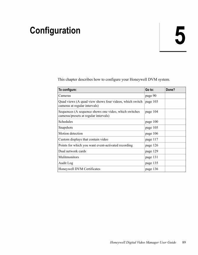
Honeywell Digital Video Manager User Guide 89
5Configuration
This chapter describes how to configure your Honeywell DVM system.
To configure: Go to: Done?Cameras page 90
Quad views (A quad view shows four videos, which switch cameras at regular intervals)
page 103
Sequences (A sequence shows one video, which switches cameras/presets at regular intervals)
page 104
Schedules page 100
Snapshots page 105
Motion detection page 106
Custom displays that contain video page 117
Points for which you want event-activated recording page 126
Dual network cards page 129
Mulitmonitors page 131
Audit Log page 135
Honeywell DVM Certificates page 136
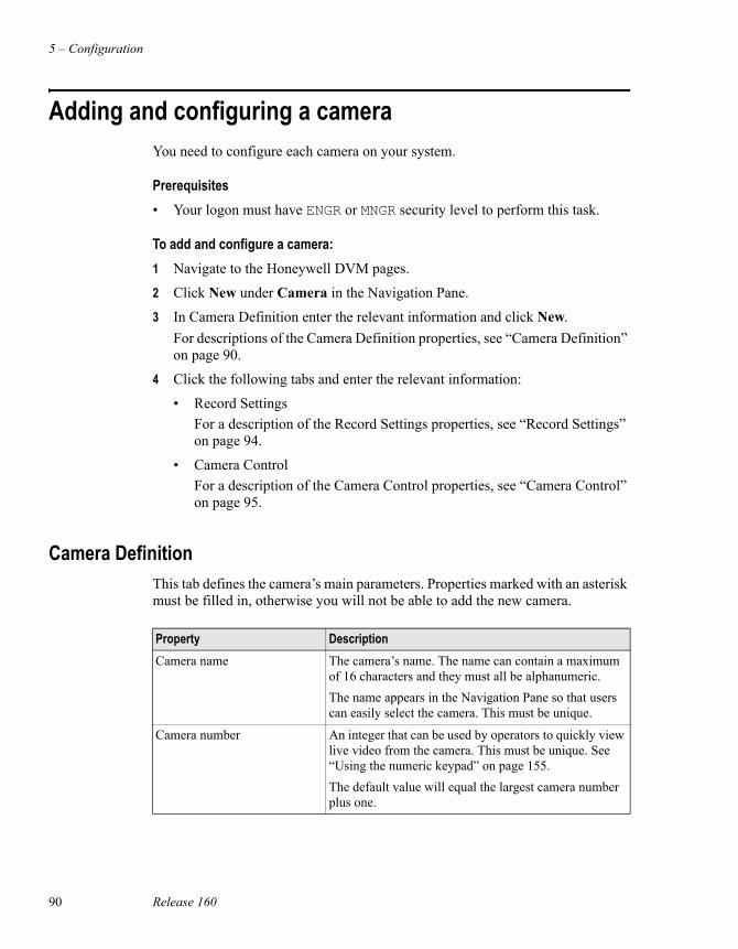
5 – Configuration
90 Release 160
Adding and configuring a cameraYou need to configure each camera on your system.
Prerequisites• Your logon must have ENGR or MNGR security level to perform this task.
To add and configure a camera:1 Navigate to the Honeywell DVM pages.
2 Click New under Camera in the Navigation Pane.
3 In Camera Definition enter the relevant information and click New. For descriptions of the Camera Definition properties, see “Camera Definition” on page 90.
4 Click the following tabs and enter the relevant information:
• Record Settings For a description of the Record Settings properties, see “Record Settings” on page 94.
• Camera ControlFor a description of the Camera Control properties, see “Camera Control” on page 95.
Camera Definition This tab defines the camera’s main parameters. Properties marked with an asterisk must be filled in, otherwise you will not be able to add the new camera.
Property DescriptionCamera name The camera’s name. The name can contain a maximum
of 16 characters and they must all be alphanumeric.The name appears in the Navigation Pane so that users can easily select the camera. This must be unique.
Camera number An integer that can be used by operators to quickly view live video from the camera. This must be unique. See “Using the numeric keypad” on page 155.The default value will equal the largest camera number plus one.
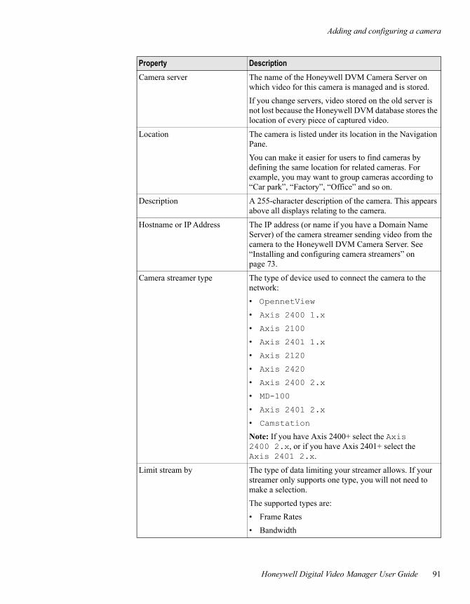
Adding and configuring a camera
Honeywell Digital Video Manager User Guide 91
Camera server The name of the Honeywell DVM Camera Server on which video for this camera is managed and is stored.If you change servers, video stored on the old server is not lost because the Honeywell DVM database stores the location of every piece of captured video.
Location The camera is listed under its location in the Navigation Pane.You can make it easier for users to find cameras by defining the same location for related cameras. For example, you may want to group cameras according to “Car park”, “Factory”, “Office” and so on.
Description A 255-character description of the camera. This appears above all displays relating to the camera.
Hostname or IP Address The IP address (or name if you have a Domain Name Server) of the camera streamer sending video from the camera to the Honeywell DVM Camera Server. See “Installing and configuring camera streamers” on page 73.
Camera streamer type The type of device used to connect the camera to the network:• OpennetView • Axis 2400 1.x • Axis 2100 • Axis 2401 1.x • Axis 2120 • Axis 2420 • Axis 2400 2.x • MD-100 • Axis 2401 2.x • Camstation Note: If you have Axis 2400+ select the Axis 2400 2.x, or if you have Axis 2401+ select the Axis 2401 2.x.
Limit stream by The type of data limiting your streamer allows. If your streamer only supports one type, you will not need to make a selection.The supported types are:• Frame Rates• Bandwidth
Property Description
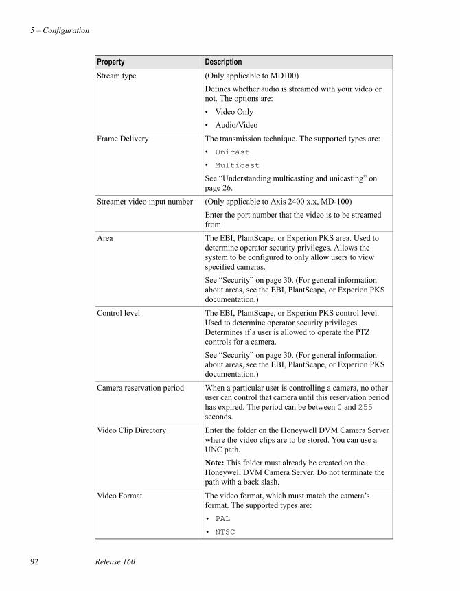
5 – Configuration
92 Release 160
Stream type (Only applicable to MD100) Defines whether audio is streamed with your video or not. The options are:• Video Only• Audio/Video
Frame Delivery The transmission technique. The supported types are:• Unicast • Multicast See “Understanding multicasting and unicasting” on page 26.
Streamer video input number (Only applicable to Axis 2400 x.x, MD-100)Enter the port number that the video is to be streamed from.
Area The EBI, PlantScape, or Experion PKS area. Used to determine operator security privileges. Allows the system to be configured to only allow users to view specified cameras.See “Security” on page 30. (For general information about areas, see the EBI, PlantScape, or Experion PKS documentation.)
Control level The EBI, PlantScape, or Experion PKS control level. Used to determine operator security privileges. Determines if a user is allowed to operate the PTZ controls for a camera. See “Security” on page 30. (For general information about areas, see the EBI, PlantScape, or Experion PKS documentation.)
Camera reservation period When a particular user is controlling a camera, no other user can control that camera until this reservation period has expired. The period can be between 0 and 255 seconds.
Video Clip Directory Enter the folder on the Honeywell DVM Camera Server where the video clips are to be stored. You can use a UNC path.Note: This folder must already be created on the Honeywell DVM Camera Server. Do not terminate the path with a back slash.
Video Format The video format, which must match the camera’s format. The supported types are:• PAL
• NTSC
Property Description
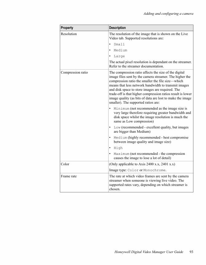
Adding and configuring a camera
Honeywell Digital Video Manager User Guide 93
Resolution The resolution of the image that is shown on the Live Video tab. Supported resolutions are:• Small • Medium • Large The actual pixel resolution is dependant on the streamer. Refer to the streamer documentation.
Compression ratio The compression ratio affects the size of the digital image files sent by the camera streamer. The higher the compression ratio the smaller the file size—which means that less network bandwidth to transmit images and disk space to store images are required. The trade-off is that higher compression ratios result is lower image quality (as bits of data are lost to make the image smaller). The supported ratios are:• Minimum (not recommended as the image size is
very large therefore requiring greater bandwidth and disk space whilst the image resolution is much the same as Low compression)
• Low (recommended - excellent quality, but images are bigger than Medium)
• Medium (highly recommended - best compromise between image quality and image size)
• High • Maximum (not recommended - the compression
causes the image to lose a lot of detail)
Color (Only applicable to Axis 2400 x.x, 2401 x.x)Image type: Color or Monochrome.
Frame rate The rate at which video frames are sent by the camera streamer when someone is viewing live video. The supported rates vary, depending on which streamer is chosen.
Property Description
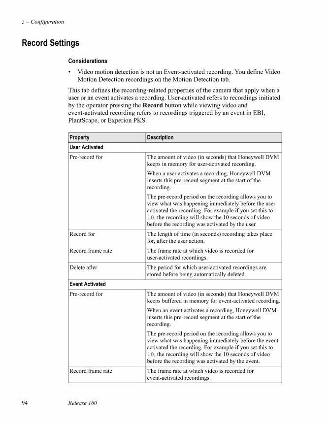
5 – Configuration
94 Release 160
Record Settings
Considerations• Video motion detection is not an Event-activated recording. You define Video
Motion Detection recordings on the Motion Detection tab.
This tab defines the recording-related properties of the camera that apply when a user or an event activates a recording. User-activated refers to recordings initiated by the operator pressing the Record button while viewing video and event-activated recording refers to recordings triggered by an event in EBI, PlantScape, or Experion PKS.
Property DescriptionUser ActivatedPre-record for The amount of video (in seconds) that Honeywell DVM
keeps in memory for user-activated recording.When a user activates a recording, Honeywell DVM inserts this pre-record segment at the start of the recording. The pre-record period on the recording allows you to view what was happening immediately before the user activated the recording. For example if you set this to 10, the recording will show the 10 seconds of video before the recording was activated by the user.
Record for The length of time (in seconds) recording takes place for, after the user action.
Record frame rate The frame rate at which video is recorded for user-activated recordings.
Delete after The period for which user-activated recordings are stored before being automatically deleted.
Event ActivatedPre-record for The amount of video (in seconds) that Honeywell DVM
keeps buffered in memory for event-activated recording.When an event activates a recording, Honeywell DVM inserts this pre-record segment at the start of the recording. The pre-record period on the recording allows you to view what was happening immediately before the event activated the recording. For example if you set this to 10, the recording will show the 10 seconds of video before the recording was activated by the event.
Record frame rate The frame rate at which video is recorded for event-activated recordings.
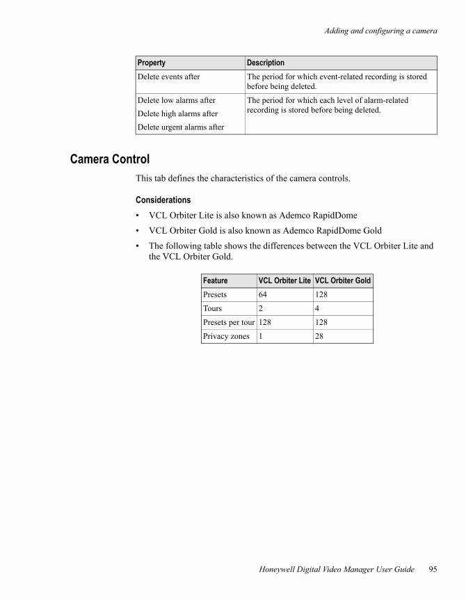
Adding and configuring a camera
Honeywell Digital Video Manager User Guide 95
Camera ControlThis tab defines the characteristics of the camera controls.
Considerations• VCL Orbiter Lite is also known as Ademco RapidDome
• VCL Orbiter Gold is also known as Ademco RapidDome Gold
• The following table shows the differences between the VCL Orbiter Lite and the VCL Orbiter Gold.
Delete events after The period for which event-related recording is stored before being deleted.
Delete low alarms afterDelete high alarms afterDelete urgent alarms after
The period for which each level of alarm-related recording is stored before being deleted.
Property Description
Feature VCL Orbiter Lite VCL Orbiter GoldPresets 64 128
Tours 2 4
Presets per tour 128 128
Privacy zones 1 28
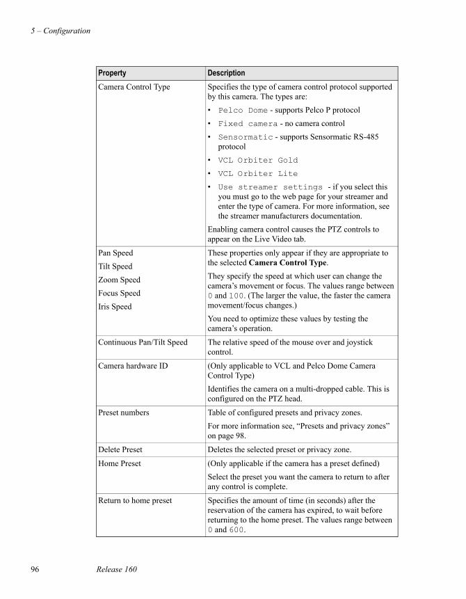
5 – Configuration
96 Release 160
Property DescriptionCamera Control Type Specifies the type of camera control protocol supported
by this camera. The types are:• Pelco Dome - supports Pelco P protocol • Fixed camera - no camera control • Sensormatic - supports Sensormatic RS-485
protocol• VCL Orbiter Gold • VCL Orbiter Lite • Use streamer settings - if you select this
you must go to the web page for your streamer and enter the type of camera. For more information, see the streamer manufacturers documentation.
Enabling camera control causes the PTZ controls to appear on the Live Video tab.
Pan SpeedTilt SpeedZoom SpeedFocus SpeedIris Speed
These properties only appear if they are appropriate to the selected Camera Control Type.They specify the speed at which user can change the camera’s movement or focus. The values range between 0 and 100. (The larger the value, the faster the camera movement/focus changes.)You need to optimize these values by testing the camera’s operation.
Continuous Pan/Tilt Speed The relative speed of the mouse over and joystick control.
Camera hardware ID (Only applicable to VCL and Pelco Dome Camera Control Type)Identifies the camera on a multi-dropped cable. This is configured on the PTZ head.
Preset numbers Table of configured presets and privacy zones.For more information see, “Presets and privacy zones” on page 98.
Delete Preset Deletes the selected preset or privacy zone.
Home Preset (Only applicable if the camera has a preset defined)Select the preset you want the camera to return to after any control is complete.
Return to home preset Specifies the amount of time (in seconds) after the reservation of the camera has expired, to wait before returning to the home preset. The values range between 0 and 600.
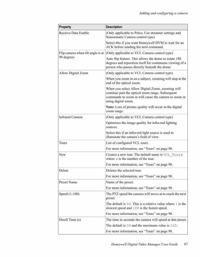
Adding and configuring a camera
Honeywell Digital Video Manager User Guide 97
Receive Data Enable (Only applicable to Pelco, Use streamer settings and Sensormatic Camera control type)Select this if you want Honeywell DVM to wait for an ACK before sending the next command.
Flip camera when tilt angle is at 90 degrees
(Only applicable to VCL Camera control type)Auto flip feature. This allows the dome to rotate 180 degrees and reposition itself for continuous viewing of a person who passes directly beneath the dome.
Allow Digital Zoom (Only applicable to VCL Camera control type)When you zoom in on a subject, zooming will stop at the end of the optical zoom. When you select Allow Digital Zoom, zooming will continue past the optical zoom range. Subsequent commands to zoom in will cause the camera to zoom in using digital zoom.Note: Loss of picture quality will occur in the digital zoom range.
Infrared Camera (Only applicable to VCL Camera control type)Optimizes the image quality for infra-red lighting sources. Select this if an infra-red light source is used to illuminate the camera’s field of view.
Tours List of configured VCL tours.For more information, see “Tours” on page 98.
New Creates a new tour. The default name is VCL_Tourx where x is the number of the tour. For more information, see “Tours” on page 98.
Delete Deletes the selected tour.For more information, see “Tours” on page 98.
Preset Name Name of the preset.For more information, see “Tours” on page 98.
Speed (1-100) The PTZ speed the camera will move at to reach the next preset.The default is 50. This is a relative value where 1 is the slowest speed and 100 is the fastest speed.For more information, see “Tours” on page 98.
Dwell Time (s) The time in seconds the camera will spend at that preset.The default is 50 and the maximum value is 120. For more information, see “Tours” on page 98.
Property Description
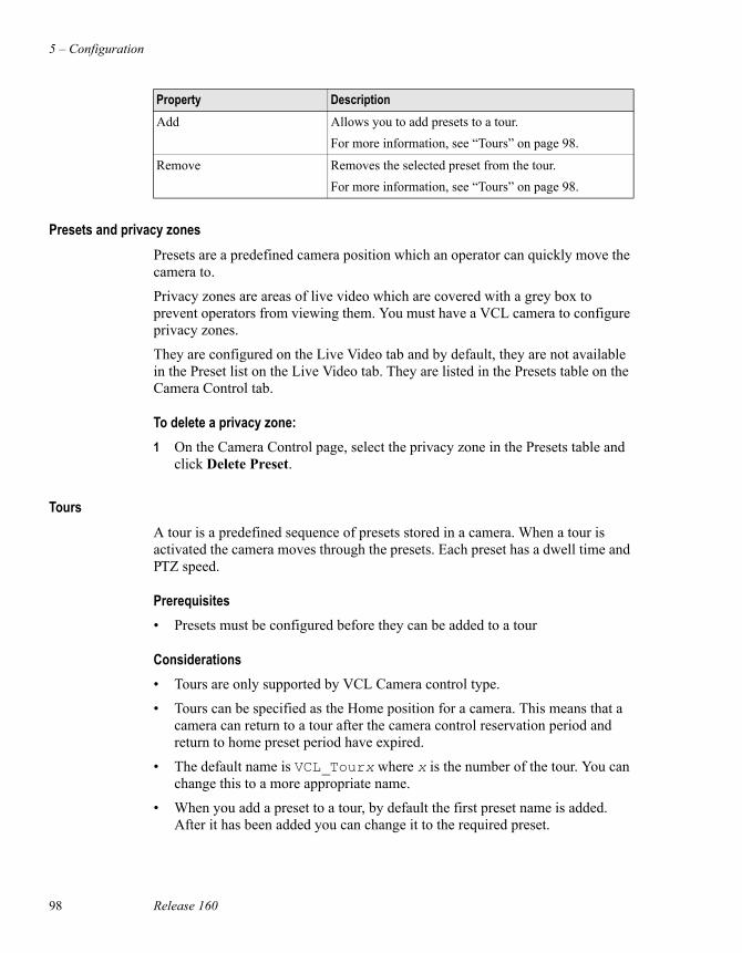
5 – Configuration
98 Release 160
Presets and privacy zonesPresets are a predefined camera position which an operator can quickly move the camera to.
Privacy zones are areas of live video which are covered with a grey box to prevent operators from viewing them. You must have a VCL camera to configure privacy zones.
They are configured on the Live Video tab and by default, they are not available in the Preset list on the Live Video tab. They are listed in the Presets table on the Camera Control tab.
To delete a privacy zone:1 On the Camera Control page, select the privacy zone in the Presets table and
click Delete Preset.
ToursA tour is a predefined sequence of presets stored in a camera. When a tour is activated the camera moves through the presets. Each preset has a dwell time and PTZ speed.
Prerequisites• Presets must be configured before they can be added to a tour
Considerations• Tours are only supported by VCL Camera control type.
• Tours can be specified as the Home position for a camera. This means that a camera can return to a tour after the camera control reservation period and return to home preset period have expired.
• The default name is VCL_Tourx where x is the number of the tour. You can change this to a more appropriate name.
• When you add a preset to a tour, by default the first preset name is added. After it has been added you can change it to the required preset.
Add Allows you to add presets to a tour.For more information, see “Tours” on page 98.
Remove Removes the selected preset from the tour.For more information, see “Tours” on page 98.
Property Description
Adding and configuring a camera
Honeywell Digital Video Manager User Guide 99
• The default PTZ speed is 50.The slowest speed is 1 and the fastest is 100.
• The default dwell time is 50. The maximum dwell time is 120 seconds.
To create a tour:1 Click New.
2 Select the default tour name and enter an appropriate name.
3 Click Add to add a preset to the tour.
4 To change the preset, select the preset name and the list of preset names will be available. Select the required preset name
5 To change the speed, select the value and enter the required speed.
6 To change the dwell time, select the value and enter the required dwell time.
7 Repeat steps 3 to 6 until all of the required presets have been added to the tour.
To remove a preset from a tour:1 Select the Preset Name you want to remove.
2 Click Remove.
To delete a tour:1 Select the tour from the Tours list.
2 Click Delete.
5 – Configuration
100 Release 160
Creating a scheduleA schedule defines the recording or video motion detection requirements at a predetermined time for a particular camera that will occur only once.
A recurring schedule defines the recording or video motion detection requirements at a predetermined time for a particular camera that will occur at the same time each day, week or month.
Honeywell DVM allows you to define two types of schedules, Recording or Motion Detection.
A Recording schedule is set up to start recording at specific times.
A Motion Detection schedule is set up to start detecting motion during specified times. The actions carried out when motion is detected are specified on the Motion Detection tab.
Prerequisites• Your logon must have ENGR or MNGR security level to perform this task.
• You can only add a camera to a schedule if you have already configured the camera.
Considerations• Motion detection schedules must not overlap.
To create a schedule:1 Click the camera under Camera in the Navigation Pane.
2 Click the Schedules tab, and then click Create a new schedule.
3 Specify the schedule details as described in the following table.
Property DescriptionType The type of schedule. The types are:
• Recording • Motion Detection
StartEnd
The date/time at which the schedule starts and stops.To specify the times, click each unit (hour and minute) and type the appropriate value.
Notes Any comments about the schedule. (When searching for recordings associated with this schedule, you can enter words and phrases contained in these notes—see “Searching for recorded video” on page 150.)
Creating a schedule
Honeywell Digital Video Manager User Guide 101
4 Click OK.
Frame rate (Only applicable to a Recording schedule)The frame rate at which the video is recorded.
Delete after (Only applicable to Recording schedule)The time the recording is kept before it is automatically deleted.
Recurring Select No if you only want one recording.Otherwise, select how often you want the recording to take place. The recurrence options are:• Daily • Weekly • Monthly
End after (Only applicable if you select a recurrence.)The length of time you want the recurrence to last.
Property Description
5 – Configuration
102 Release 160
Deleting schedulesA schedule defines the recording or video motion detection requirements at a predetermined time for a particular camera that will occur only once.
A recurring schedule defines the recording or video motion detection requirements at a predetermined time for a particular camera that will occur at the same time each day, week or month.
Prerequisites• Your logon must have ENGR or MNGR security level to perform this task.
To delete a schedule:1 Select the camera.
2 Click the Schedule tab.
3 Select the start day of the recording or motion detection schedule.
4 From the list, select the schedule you want to delete. The schedule’s details will appear in the bottom right corner of the display.
5 Click the Delete button.
To delete a recurring schedule:1 Select the camera.
2 Click the Schedule tab.
3 Select the start day of the recording or motion detection schedule.
4 From the list, select the schedule you want to delete. The schedule’s details will appear in the bottom right corner of the display.
5 If you only want to delete the schedule for that day, click Delete.If you want to delete all occurrences of this schedule, click Delete all occurrences. (This button only appears when you select a recurring schedule.)
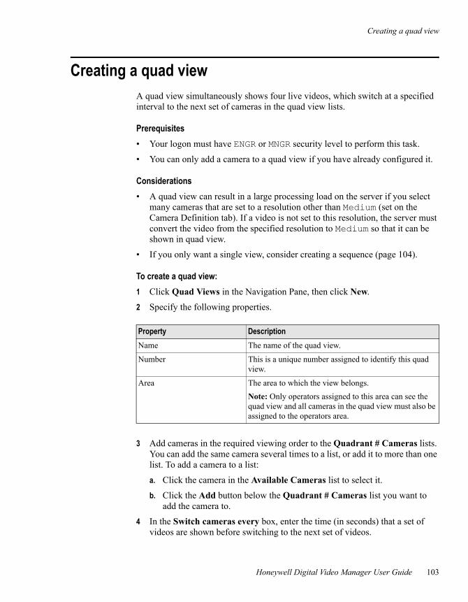
Creating a quad view
Honeywell Digital Video Manager User Guide 103
Creating a quad viewA quad view simultaneously shows four live videos, which switch at a specified interval to the next set of cameras in the quad view lists.
Prerequisites• Your logon must have ENGR or MNGR security level to perform this task.
• You can only add a camera to a quad view if you have already configured it.
Considerations• A quad view can result in a large processing load on the server if you select
many cameras that are set to a resolution other than Medium (set on the Camera Definition tab). If a video is not set to this resolution, the server must convert the video from the specified resolution to Medium so that it can be shown in quad view.
• If you only want a single view, consider creating a sequence (page 104).
To create a quad view:1 Click Quad Views in the Navigation Pane, then click New.
2 Specify the following properties.
3 Add cameras in the required viewing order to the Quadrant # Cameras lists. You can add the same camera several times to a list, or add it to more than one list. To add a camera to a list:
a. Click the camera in the Available Cameras list to select it.
b. Click the Add button below the Quadrant # Cameras list you want to add the camera to.
4 In the Switch cameras every box, enter the time (in seconds) that a set of videos are shown before switching to the next set of videos.
Property DescriptionName The name of the quad view.
Number This is a unique number assigned to identify this quad view.
Area The area to which the view belongs. Note: Only operators assigned to this area can see the quad view and all cameras in the quad view must also be assigned to the operators area.
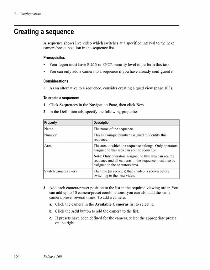
5 – Configuration
104 Release 160
Creating a sequenceA sequence shows live video which switches at a specified interval to the next camera/preset position in the sequence list.
Prerequisites• Your logon must have ENGR or MNGR security level to perform this task.
• You can only add a camera to a sequence if you have already configured it.
Considerations• As an alternative to a sequence, consider creating a quad view (page 103).
To create a sequence:1 Click Sequences in the Navigation Pane, then click New.
2 In the Definition tab, specify the following properties.
3 Add each camera/preset position to the list in the required viewing order. You can add up to 10 camera/preset combinations; you can also add the same camera/preset several times. To add a camera:
a. Click the camera in the Available Cameras list to select it.
b. Click the Add button to add the camera to the list.
c. If presets have been defined for the camera, select the appropriate preset on the right.
Property DescriptionName The name of the sequence.
Number This is a unique number assigned to identify this sequence.
Area The area to which the sequence belongs. Only operators assigned to this area can see the sequence.Note: Only operators assigned to this area can see the sequence and all cameras in the sequence must also be assigned to the operators area.
Switch cameras every The time (in seconds) that a video is shown before switching to the next video.
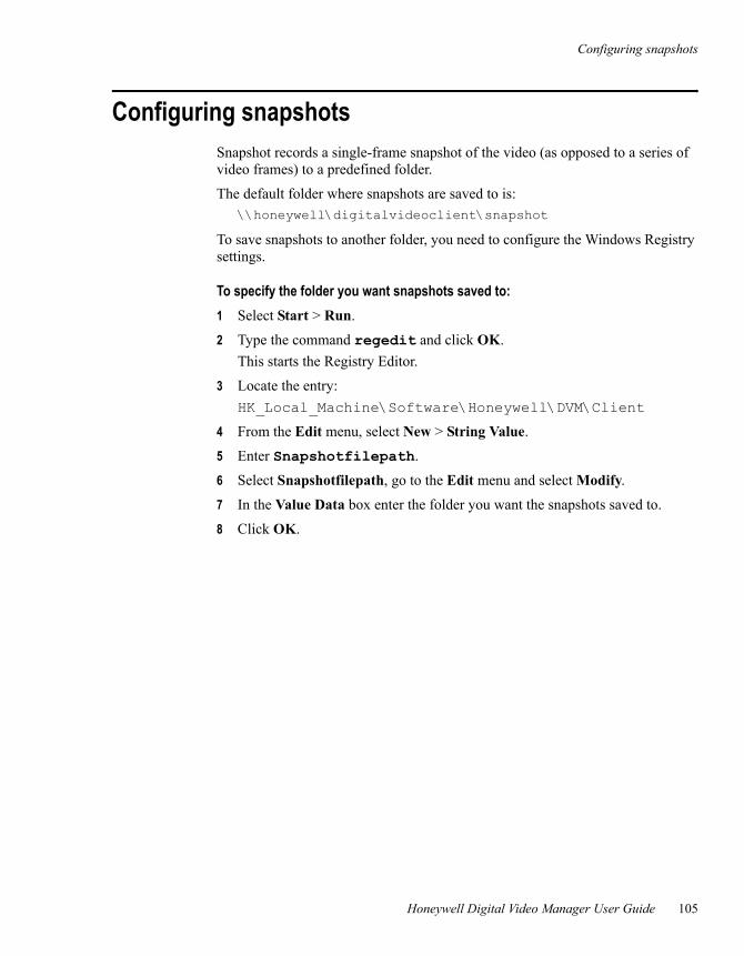
Configuring snapshots
Honeywell Digital Video Manager User Guide 105
Configuring snapshotsSnapshot records a single-frame snapshot of the video (as opposed to a series of video frames) to a predefined folder.
The default folder where snapshots are saved to is:\\honeywell\digitalvideoclient\snapshot
To save snapshots to another folder, you need to configure the Windows Registry settings.
To specify the folder you want snapshots saved to:1 Select Start > Run.
2 Type the command regedit and click OK.This starts the Registry Editor.
3 Locate the entry:HK_Local_Machine\Software\Honeywell\DVM\Client
4 From the Edit menu, select New > String Value.
5 Enter Snapshotfilepath.
6 Select Snapshotfilepath, go to the Edit menu and select Modify.
7 In the Value Data box enter the folder you want the snapshots saved to.
8 Click OK.
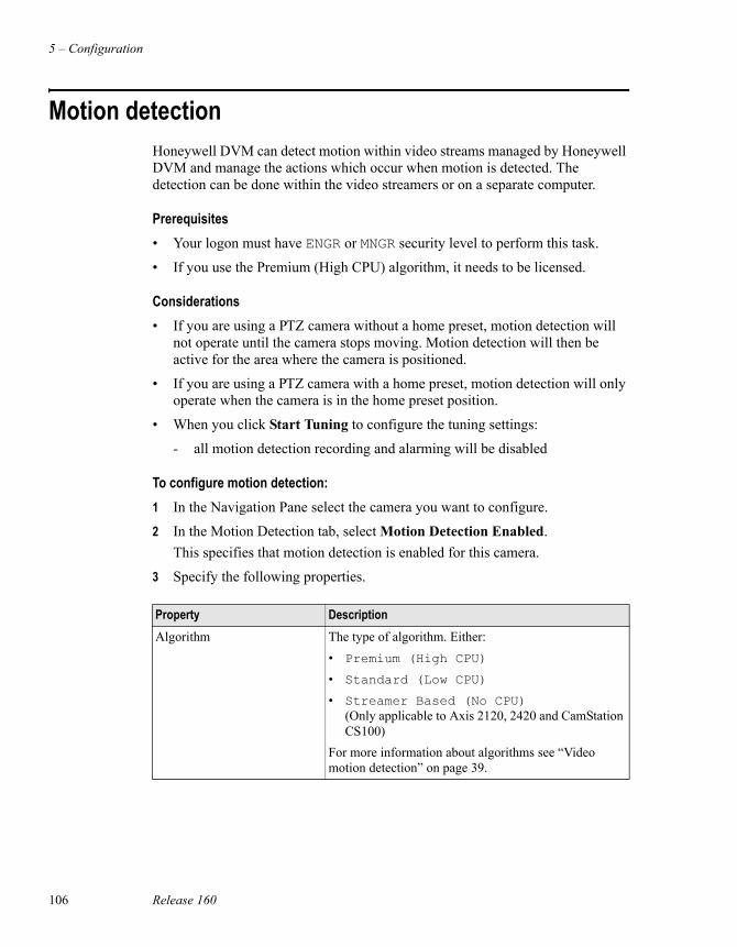
5 – Configuration
106 Release 160
Motion detectionHoneywell DVM can detect motion within video streams managed by Honeywell DVM and manage the actions which occur when motion is detected. The detection can be done within the video streamers or on a separate computer.
Prerequisites• Your logon must have ENGR or MNGR security level to perform this task.
• If you use the Premium (High CPU) algorithm, it needs to be licensed.
Considerations• If you are using a PTZ camera without a home preset, motion detection will
not operate until the camera stops moving. Motion detection will then be active for the area where the camera is positioned.
• If you are using a PTZ camera with a home preset, motion detection will only operate when the camera is in the home preset position.
• When you click Start Tuning to configure the tuning settings:
- all motion detection recording and alarming will be disabled
To configure motion detection:1 In the Navigation Pane select the camera you want to configure.
2 In the Motion Detection tab, select Motion Detection Enabled. This specifies that motion detection is enabled for this camera.
3 Specify the following properties.
Property DescriptionAlgorithm The type of algorithm. Either:
• Premium (High CPU) • Standard (Low CPU) • Streamer Based (No CPU)
(Only applicable to Axis 2120, 2420 and CamStation CS100)
For more information about algorithms see “Video motion detection” on page 39.
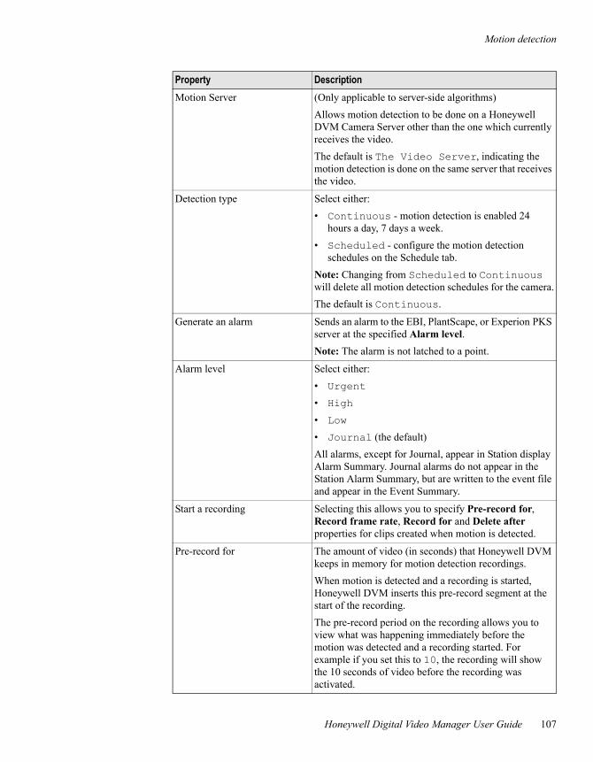
Motion detection
Honeywell Digital Video Manager User Guide 107
Motion Server (Only applicable to server-side algorithms)Allows motion detection to be done on a Honeywell DVM Camera Server other than the one which currently receives the video.The default is The Video Server, indicating the motion detection is done on the same server that receives the video.
Detection type Select either:• Continuous - motion detection is enabled 24
hours a day, 7 days a week.• Scheduled - configure the motion detection
schedules on the Schedule tab.Note: Changing from Scheduled to Continuous will delete all motion detection schedules for the camera.The default is Continuous.
Generate an alarm Sends an alarm to the EBI, PlantScape, or Experion PKS server at the specified Alarm level. Note: The alarm is not latched to a point.
Alarm level Select either:• Urgent • High • Low • Journal (the default)All alarms, except for Journal, appear in Station display Alarm Summary. Journal alarms do not appear in the Station Alarm Summary, but are written to the event file and appear in the Event Summary.
Start a recording Selecting this allows you to specify Pre-record for, Record frame rate, Record for and Delete after properties for clips created when motion is detected.
Pre-record for The amount of video (in seconds) that Honeywell DVM keeps in memory for motion detection recordings.When motion is detected and a recording is started, Honeywell DVM inserts this pre-record segment at the start of the recording. The pre-record period on the recording allows you to view what was happening immediately before the motion was detected and a recording started. For example if you set this to 10, the recording will show the 10 seconds of video before the recording was activated.
Property Description
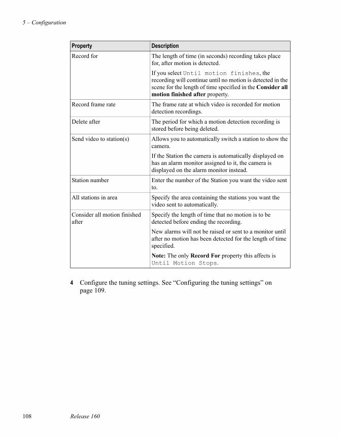
5 – Configuration
108 Release 160
4 Configure the tuning settings. See “Configuring the tuning settings” on page 109.
Record for The length of time (in seconds) recording takes place for, after motion is detected.If you select Until motion finishes, the recording will continue until no motion is detected in the scene for the length of time specified in the Consider all motion finished after property.
Record frame rate The frame rate at which video is recorded for motion detection recordings.
Delete after The period for which a motion detection recording is stored before being deleted.
Send video to station(s) Allows you to automatically switch a station to show the camera. If the Station the camera is automatically displayed on has an alarm monitor assigned to it, the camera is displayed on the alarm monitor instead.
Station number Enter the number of the Station you want the video sent to.
All stations in area Specify the area containing the stations you want the video sent to automatically.
Consider all motion finished after
Specify the length of time that no motion is to be detected before ending the recording.New alarms will not be raised or sent to a monitor until after no motion has been detected for the length of time specified.Note: The only Record For property this affects is Until Motion Stops.
Property Description
Motion detection
Honeywell Digital Video Manager User Guide 109
Configuring the tuning settingsThe tuning properties are specific to each algorithm available for selection in the Algorithm property. These settings determine the cameras sensitivity to detecting motion.
Considerations• When you click Start Tuning to configure the tuning settings:
- all motion detection recording and alarming will be disabled
- (Premium algorithm only) the first 20 frames are used to learn the statistics of the field of view
- (Premium algorithm only) the next 60 frames are required to set up the information learned by Honeywell DVM during the first 20 frames. Therefore motion will not be detected in the field of view during the first 80 frames.
• (Premium algorithm only) After PTZ operation, the video motion detection algorithm must learn the statistics of the field of view again, therefore motion will not be detected for the next 80 frames.
• It is recommended that only 40% of the CPU is used to process video motion detection.
• Region of Interest:
- should be in a well lit area, with illumination intensity greater than 300 LUX
- avoid setting a complete region of interest over a dark or black area.
• High quality cameras with minimal noise should be used for video motion detection.
• Streamers and streamer power supplies can introduce noise which can cause alarms. Power supply noise filtering may be required.
• When camera output is split and fed into the streamer, the signal may be weaker which will affect the detection algorithm.
• Monochrome camera provide better images for the motion detection algorithm.
• Reflections occurring in windows and mirrors will activate motion detection.
NoteCamera noise in low light areas may cause false alarms.
5 – Configuration
110 Release 160
• Sudden changes in lighting will activate motion detection. An example of a sudden change in lighting is when car headlights are turned on or off. Gradual changes should not activate motion detection.
• (Standard Algorithm only) Be aware of slight changes in motion. For example, tree leaves moving in the field of view.
• Changing the viewing resolution or compression ratio of the camera configuration will affect the performance of video motion detection. The higher the resolution and compression ratio, the more video motion detection processing required.
• If you use the standard and advanced algorithms on your system, make sure you account for the processing overheads of both algorithms.
To configure the tuning settings:1 Click Start tuning.
2 Enter the properties for the Algorithm you selected.
- “Standard (Low CPU) Algorithm Tuning Properties” on page 111
- “Premium (High CPU) Algorithm Tuning Properties” on page 112
- “Streamer Based (No CPU) Algorithm Tuning Properties for Axis Streamers” on page 115
- “Streamer Based (No CPU) Algorithm Tuning Properties for CamStation CS100 Streamers” on page 116
3 Click Finish tuning.
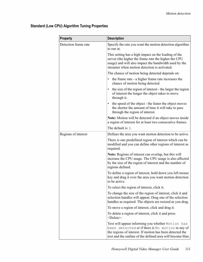
Motion detection
Honeywell Digital Video Manager User Guide 111
Standard (Low CPU) Algorithm Tuning Properties
Property DescriptionDetection frame rate Specify the rate you want the motion detection algorithm
to run at. This setting has a high impact on the loading of the server (the higher the frame rate the higher the CPU usage) and will also impact the bandwidth used by the streamer when motion detection is activated.The chance of motion being detected depends on:• the frame rate - a higher frame rate increases the
chance of motion being detected.• the size of the region of interest - the larger the region
of interest the longer the object takes to move through it.
• the speed of the object - the faster the object moves the shorter the amount of time it will take to pass through the region of interest.
Note: Motion will be detected if an object moves inside a region of interest for at least two consecutive frames.The default is 3.
Regions of interest Defines the area you want motion detection to be active. There is one predefined region of interest which can be modified and you can define other regions of interest as required.Note: Regions of interest can overlap, but this will increase the CPU usage. The CPU usage is also affected by the size of the region of interest and the number of regions defined.To define a region of interest, hold down you left mouse key and drag it over the area you want motion detection to be active. To select the region of interest, click it.To change the size of the region of interest, click it and selection handles will appear. Drag one of the selection handles as required. The objects are resized as you drag. To move a region of interest, click and drag it.To delete a region of interest, click it and press <Delete>.Text will appear informing you whether Motion has been detected or if there is No motion in any of the regions of interest. If motion has been detected the text and the outline of the defined area will become blue.
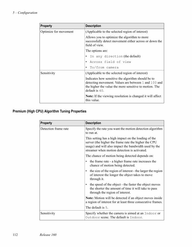
5 – Configuration
112 Release 160
Premium (High CPU) Algorithm Tuning Properties
Optimize for movement (Applicable to the selected region of interest)Allows you to optimize the algorithm to more successfully detect movement either across or down the field of view.The options are:• In any direction (the default) • Across field of view • To/from camera
Sensitivity (Applicable to the selected region of interest)Indicates how sensitive the algorithm should be to detecting movement. Values are between 1 and 100 and the higher the value the more sensitive to motion. The default is 40.Note: If the viewing resolution is changed it will affect this value.
Property Description
Property DescriptionDetection frame rate Specify the rate you want the motion detection algorithm
to run at. This setting has a high impact on the loading of the server (the higher the frame rate the higher the CPU usage) and will also impact the bandwidth used by the streamer when motion detection is activated.The chance of motion being detected depends on:• the frame rate - a higher frame rate increases the
chance of motion being detected.• the size of the region of interest - the larger the region
of interest the longer the object takes to move through it.
• the speed of the object - the faster the object moves the shorter the amount of time it will take to pass through the region of interest.
Note: Motion will be detected if an object moves inside a region of interest for at least three consecutive frames.The default is 5.
Sensitivity Specify whether the camera is aimed at an Indoor or Outdoor scene. The default is Indoor.
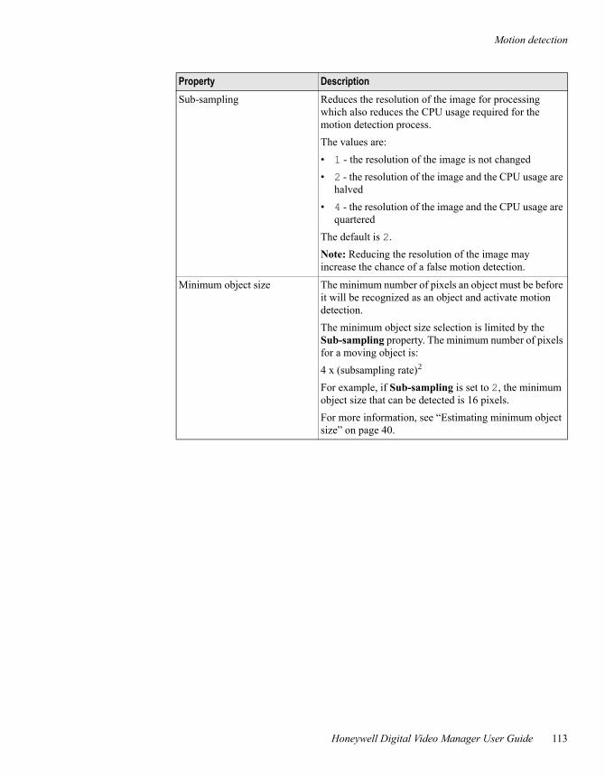
Motion detection
Honeywell Digital Video Manager User Guide 113
Sub-sampling Reduces the resolution of the image for processing which also reduces the CPU usage required for the motion detection process.The values are:• 1 - the resolution of the image is not changed• 2 - the resolution of the image and the CPU usage are
halved• 4 - the resolution of the image and the CPU usage are
quarteredThe default is 2.Note: Reducing the resolution of the image may increase the chance of a false motion detection.
Minimum object size The minimum number of pixels an object must be before it will be recognized as an object and activate motion detection.The minimum object size selection is limited by the Sub-sampling property. The minimum number of pixels for a moving object is:4 x (subsampling rate)2 For example, if Sub-sampling is set to 2, the minimum object size that can be detected is 16 pixels.For more information, see “Estimating minimum object size” on page 40.
Property Description
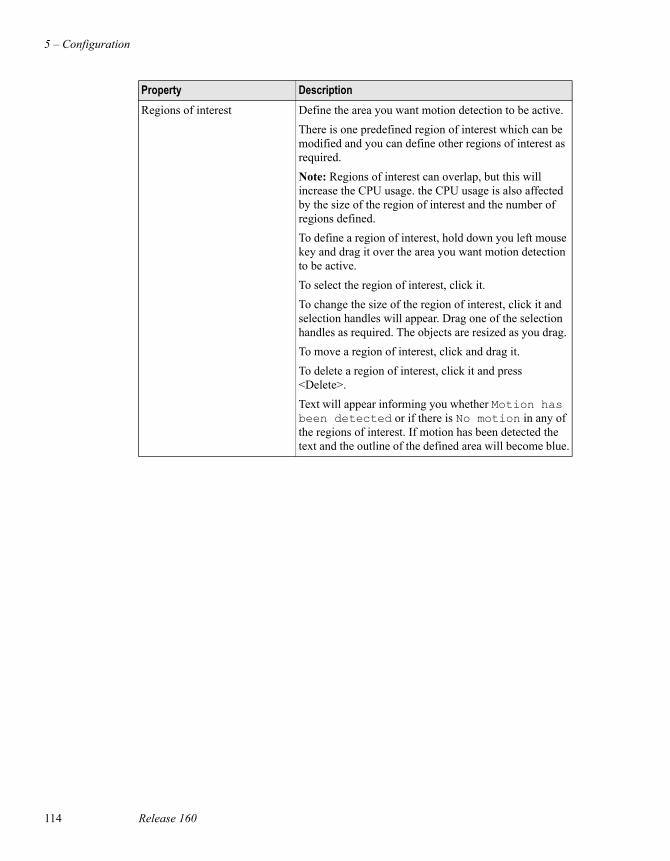
5 – Configuration
114 Release 160
Regions of interest Define the area you want motion detection to be active. There is one predefined region of interest which can be modified and you can define other regions of interest as required.Note: Regions of interest can overlap, but this will increase the CPU usage. the CPU usage is also affected by the size of the region of interest and the number of regions defined.To define a region of interest, hold down you left mouse key and drag it over the area you want motion detection to be active. To select the region of interest, click it.To change the size of the region of interest, click it and selection handles will appear. Drag one of the selection handles as required. The objects are resized as you drag. To move a region of interest, click and drag it.To delete a region of interest, click it and press <Delete>.Text will appear informing you whether Motion has been detected or if there is No motion in any of the regions of interest. If motion has been detected the text and the outline of the defined area will become blue.
Property Description
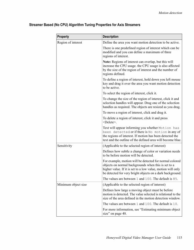
Motion detection
Honeywell Digital Video Manager User Guide 115
Streamer Based (No CPU) Algorithm Tuning Properties for Axis Streamers
Property DescriptionRegion of interest Define the area you want motion detection to be active.
There is one predefined region of interest which can be modified and you can define a maximum of three regions of interest.Note: Regions of interest can overlap, but this will increase the CPU usage. the CPU usage is also affected by the size of the region of interest and the number of regions defined.To define a region of interest, hold down you left mouse key and drag it over the area you want motion detection to be active. To select the region of interest, click it.To change the size of the region of interest, click it and selection handles will appear. Drag one of the selection handles as required. The objects are resized as you drag. To move a region of interest, click and drag it.To delete a region of interest, click it and press <Delete>.Text will appear informing you whether Motion has been detected or if there is No motion in any of the regions of interest. If motion has been detected the text and the outline of the defined area will become blue.
Sensitivity (Applicable to the selected region of interest)Defines how subtle a change of color or variation needs to be before motion will be detected.For example, motion will be detected for normal colored objects on normal backgrounds when this is set to a higher value. If it is set to a low value, motion will only be detected for very bright objects on a dark background.The values are between 1 and 100. The default is 85.
Minimum object size (Applicable to the selected region of interest)Defines how large a moving object must be before motion is detected. The value selected is relational to the size of the area defined in the motion detection window.The values are between 1 and 100. The default is 10.For more information, see “Estimating minimum object size” on page 40.
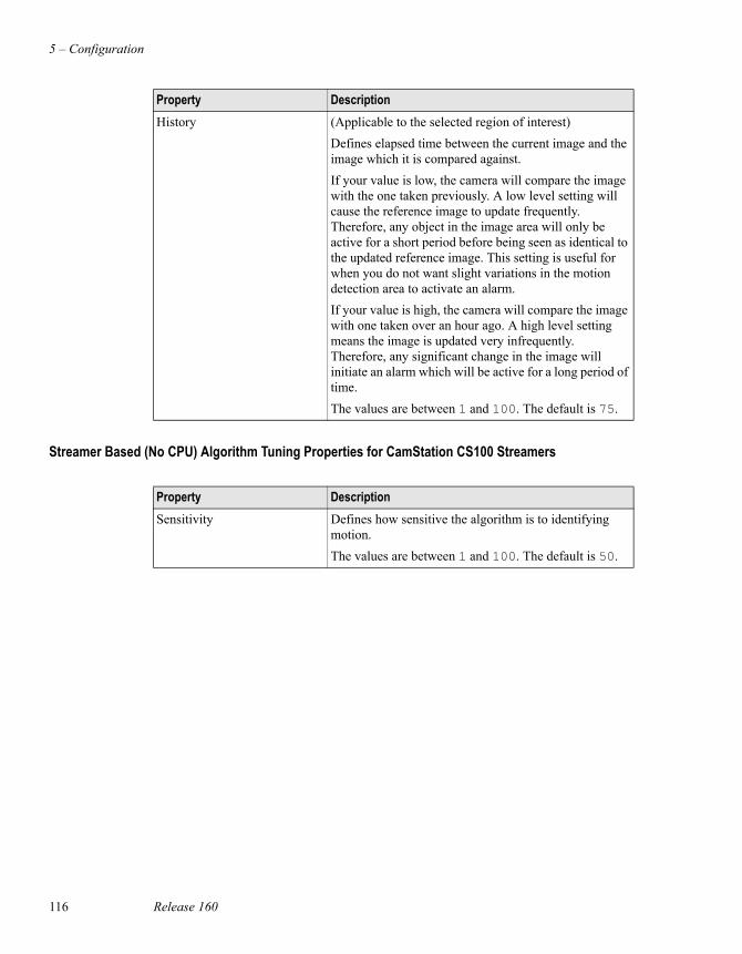
5 – Configuration
116 Release 160
Streamer Based (No CPU) Algorithm Tuning Properties for CamStation CS100 Streamers
History (Applicable to the selected region of interest)Defines elapsed time between the current image and the image which it is compared against.If your value is low, the camera will compare the image with the one taken previously. A low level setting will cause the reference image to update frequently. Therefore, any object in the image area will only be active for a short period before being seen as identical to the updated reference image. This setting is useful for when you do not want slight variations in the motion detection area to activate an alarm.If your value is high, the camera will compare the image with one taken over an hour ago. A high level setting means the image is updated very infrequently. Therefore, any significant change in the image will initiate an alarm which will be active for a long period of time.The values are between 1 and 100. The default is 75.
Property Description
Property DescriptionSensitivity Defines how sensitive the algorithm is to identifying
motion.The values are between 1 and 100. The default is 50.
Including video in custom displays
Honeywell Digital Video Manager User Guide 117
Including video in custom displaysYou can include Honeywell DVM video players in custom displays, which you create using Display Builder or HMIWeb Display Builder.
Display Builder is the display-creation tool supplied with EBI, PlantScape, or Experion PKS. Displays created with this tool have a proprietary “DSP” format.
HMIWeb Display Builder is the display-creation tool supplied with EBI, PlantScape, or Experion PKS. It is used to create web-based displays.
Displays created using Display BuilderThis section only describes how to add a video player to a display—for detailed information about creating displays, see Display Builder’s help.
To add a video player to a display:1 Add a SafeBrowse object to the display, and then adjust its size and position.
The required size depends on several factors including the image size (Resolution on the Camera Definition tab) and screen resolution. In practise, you need to check the display in Station, and then make appropriate adjustments in Display Builder.
2 While the object is selected, open the Properties window and click the Details tab.
3 In URL enter one of the following,
- To view a camerahttp://ServerName/HWDVSWebServer/camera.asp?CameraNumber=number
or http://ServerName/HWDVSWebServer/camera.asp?CameraName=name
- To view a specific preset on a camerahttp://ServerName/HWDVSWebServer/camera.asp?CameraNumber=number&PresetName=PresetName
orhttp://ServerName/HWDVSWebServer/camera.asp?CameraName=name&PresetName=PresetName
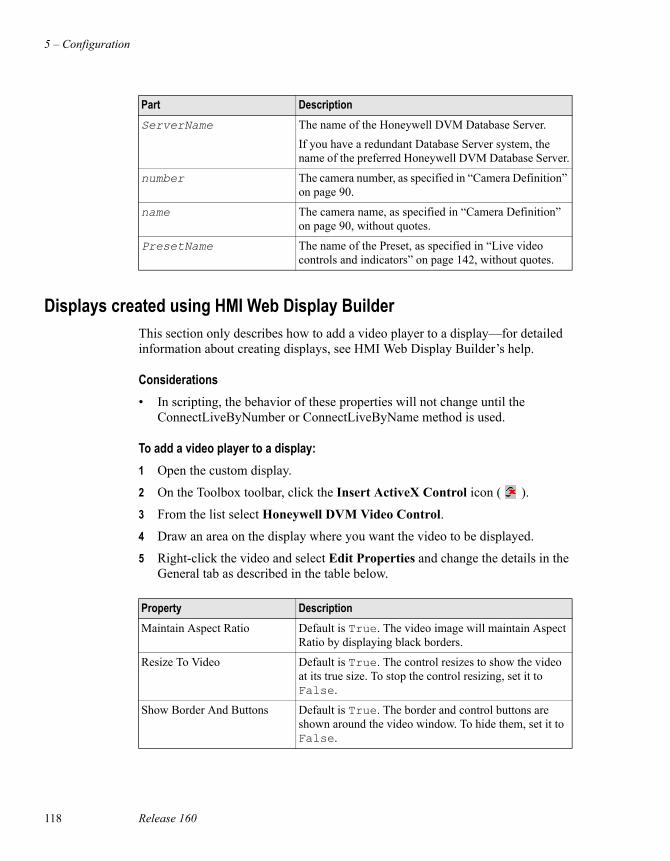
5 – Configuration
118 Release 160
Displays created using HMI Web Display BuilderThis section only describes how to add a video player to a display—for detailed information about creating displays, see HMI Web Display Builder’s help.
Considerations• In scripting, the behavior of these properties will not change until the
ConnectLiveByNumber or ConnectLiveByName method is used.
To add a video player to a display:1 Open the custom display.
2 On the Toolbox toolbar, click the Insert ActiveX Control icon ( ).
3 From the list select Honeywell DVM Video Control.
4 Draw an area on the display where you want the video to be displayed.
5 Right-click the video and select Edit Properties and change the details in the General tab as described in the table below.
Part DescriptionServerName The name of the Honeywell DVM Database Server.
If you have a redundant Database Server system, the name of the preferred Honeywell DVM Database Server.
number The camera number, as specified in “Camera Definition” on page 90.
name The camera name, as specified in “Camera Definition” on page 90, without quotes.
PresetName The name of the Preset, as specified in “Live video controls and indicators” on page 142, without quotes.
Property DescriptionMaintain Aspect Ratio Default is True. The video image will maintain Aspect
Ratio by displaying black borders.
Resize To Video Default is True. The control resizes to show the video at its true size. To stop the control resizing, set it to False.
Show Border And Buttons Default is True. The border and control buttons are shown around the video window. To hide them, set it to False.
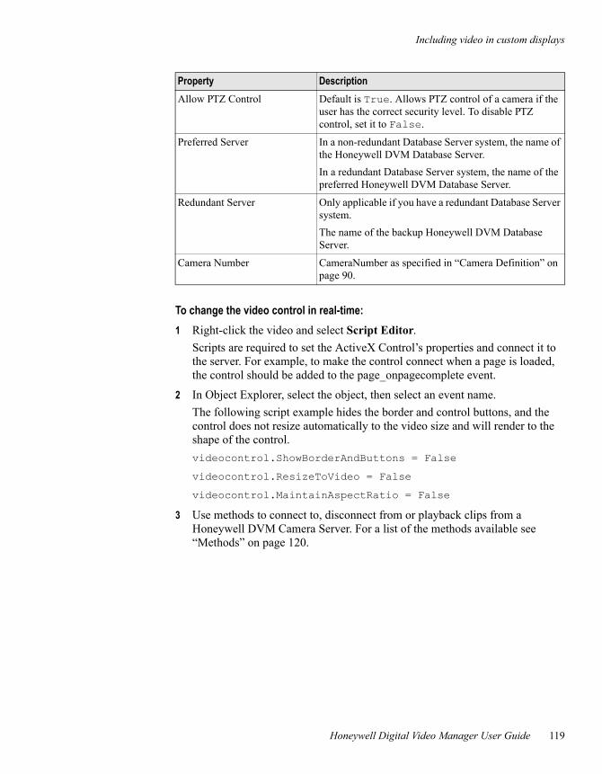
Including video in custom displays
Honeywell Digital Video Manager User Guide 119
To change the video control in real-time:1 Right-click the video and select Script Editor.
Scripts are required to set the ActiveX Control’s properties and connect it to the server. For example, to make the control connect when a page is loaded, the control should be added to the page_onpagecomplete event.
2 In Object Explorer, select the object, then select an event name.The following script example hides the border and control buttons, and the control does not resize automatically to the video size and will render to the shape of the control.videocontrol.ShowBorderAndButtons = False
videocontrol.ResizeToVideo = False
videocontrol.MaintainAspectRatio = False
3 Use methods to connect to, disconnect from or playback clips from a Honeywell DVM Camera Server. For a list of the methods available see “Methods” on page 120.
Allow PTZ Control Default is True. Allows PTZ control of a camera if the user has the correct security level. To disable PTZ control, set it to False.
Preferred Server In a non-redundant Database Server system, the name of the Honeywell DVM Database Server.In a redundant Database Server system, the name of the preferred Honeywell DVM Database Server.
Redundant Server Only applicable if you have a redundant Database Server system.The name of the backup Honeywell DVM Database Server.
Camera Number CameraNumber as specified in “Camera Definition” on page 90.
Property Description
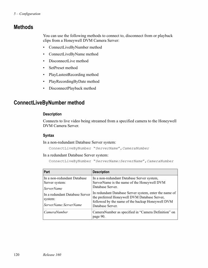
5 – Configuration
120 Release 160
MethodsYou can use the following methods to connect to, disconnect from or playback clips from a Honeywell DVM Camera Server:
• ConnectLiveByNumber method
• ConnectLiveByName method
• DisconnectLive method
• SetPreset method
• PlayLastestRecording method
• PlayRecordingByDate method
• DisconnectPlayback method
ConnectLiveByNumber method
DescriptionConnects to live video being streamed from a specified camera to the Honeywell DVM Camera Server.
SyntaxIn a non-redundant Database Server system:
ConnectLiveByNumber “ServerName”,CameraNumber
In a redundant Database Server system:ConnectLiveByNumber “ServerName:ServerName”,CameraNumber
Part DescriptionIn a non-redundant Database Server system:ServerNameIn a redundant Database Server system:ServerName:ServerName
In a non-redundant Database Server system, ServerName is the name of the Honeywell DVM Database Server. In redundant Database Server system, enter the name of the preferred Honeywell DVM Database Server, followed by the name of the backup Honeywell DVM Database Server.
CameraNumber CameraNumber as specified in “Camera Definition” on page 90.
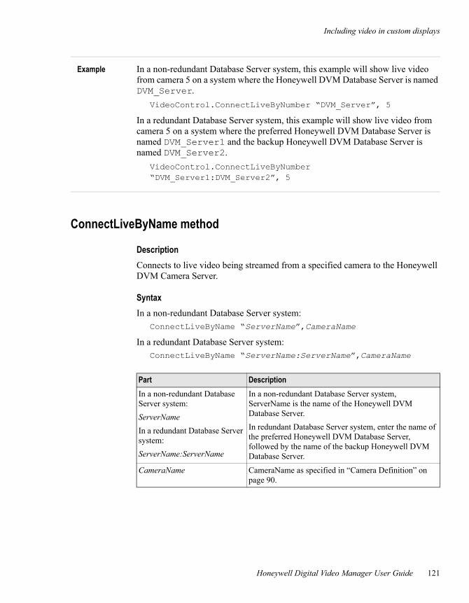
Including video in custom displays
Honeywell Digital Video Manager User Guide 121
Example In a non-redundant Database Server system, this example will show live video from camera 5 on a system where the Honeywell DVM Database Server is named DVM_Server.
VideoControl.ConnectLiveByNumber “DVM_Server”, 5
In a redundant Database Server system, this example will show live video from camera 5 on a system where the preferred Honeywell DVM Database Server is named DVM_Server1 and the backup Honeywell DVM Database Server is named DVM_Server2.
VideoControl.ConnectLiveByNumber “DVM_Server1:DVM_Server2”, 5
ConnectLiveByName method
DescriptionConnects to live video being streamed from a specified camera to the Honeywell DVM Camera Server.
SyntaxIn a non-redundant Database Server system:
ConnectLiveByName “ServerName”,CameraName
In a redundant Database Server system:ConnectLiveByName “ServerName:ServerName”,CameraName
Part DescriptionIn a non-redundant Database Server system:ServerNameIn a redundant Database Server system:ServerName:ServerName
In a non-redundant Database Server system, ServerName is the name of the Honeywell DVM Database Server. In redundant Database Server system, enter the name of the preferred Honeywell DVM Database Server, followed by the name of the backup Honeywell DVM Database Server.
CameraName CameraName as specified in “Camera Definition” on page 90.
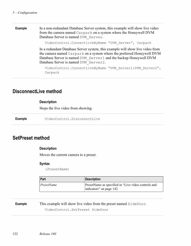
5 – Configuration
122 Release 160
Example In a non-redundant Database Server system, this example will show live video from the camera named Carpark on a system where the Honeywell DVM Database Server is named DVM_Server.
VideoControl.ConnectliveByName “DVM_Server”, Carpark
In a redundant Database Server system, this example will show live video from the camera named Carpark on a system where the preferred Honeywell DVM Database Server is named DVM_Server1 and the backup Honeywell DVM Database Server is named DVM_Server2.
VideoControl.ConnectliveByName “DVM_Server1:DVM_Server2”, Carpark
DisconnectLive method
DescriptionStops the live video from showing.
Example VideoControl.DisconnectLive
SetPreset method
DescriptionMoves the current camera to a preset.
Syntax(PresetName)
Example This example will show live video from the preset named SideDoor.VideoControl.SetPreset SideDoor
Part DescriptionPresetName PresetName as specified in “Live video controls and
indicators” on page 142.
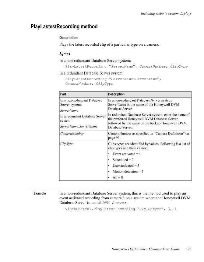
Including video in custom displays
Honeywell Digital Video Manager User Guide 123
PlayLastestRecording method
DescriptionPlays the latest recorded clip of a particular type on a camera.
SyntaxIn a non-redundant Database Server system:
PlayLatestRecording “ServerName”, CameraNumber, ClipType
In a redundant Database Server system:PlayLatestRecording “ServerName:ServerName”, CameraNumber, ClipType
Example In a non-redundant Database Server system, this is the method used to play an event activated recording from camera 3 on a system where the Honeywell DVM Database Server is named DVM_Server.
VideoControl.PlayLatestRecording “DVM_Server”, 3, 1
Part DescriptionIn a non-redundant Database Server system:ServerNameIn a redundant Database Server system:ServerName:ServerName
In a non-redundant Database Server system, ServerName is the name of the Honeywell DVM Database Server. In redundant Database Server system, enter the name of the preferred Honeywell DVM Database Server, followed by the name of the backup Honeywell DVM Database Server.
CameraNumber CameraNumber as specified in “Camera Definition” on page 90.
ClipType Clips types are identified by values. Following is a list of clip types and their values:• Event activated =1• Scheduled = 2• User activated = 3• Motion detection = 5• All = 0
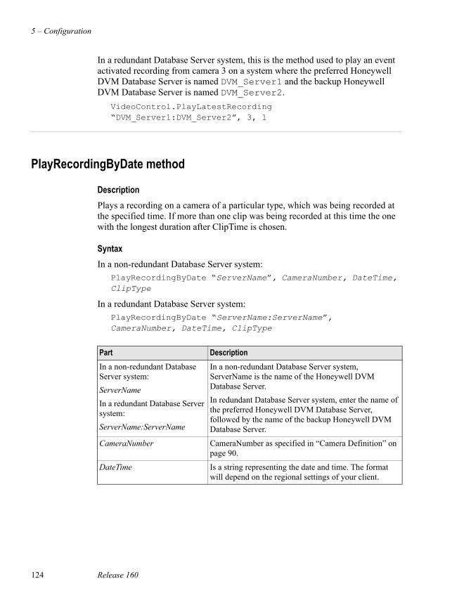
5 – Configuration
124 Release 160
In a redundant Database Server system, this is the method used to play an event activated recording from camera 3 on a system where the preferred Honeywell DVM Database Server is named DVM_Server1 and the backup Honeywell DVM Database Server is named DVM_Server2.
VideoControl.PlayLatestRecording “DVM_Server1:DVM_Server2”, 3, 1
PlayRecordingByDate method
DescriptionPlays a recording on a camera of a particular type, which was being recorded at the specified time. If more than one clip was being recorded at this time the one with the longest duration after ClipTime is chosen.
SyntaxIn a non-redundant Database Server system:
PlayRecordingByDate “ServerName”, CameraNumber, DateTime, ClipType
In a redundant Database Server system:PlayRecordingByDate “ServerName:ServerName”, CameraNumber, DateTime, ClipType
Part DescriptionIn a non-redundant Database Server system:ServerNameIn a redundant Database Server system:ServerName:ServerName
In a non-redundant Database Server system, ServerName is the name of the Honeywell DVM Database Server. In redundant Database Server system, enter the name of the preferred Honeywell DVM Database Server, followed by the name of the backup Honeywell DVM Database Server.
CameraNumber CameraNumber as specified in “Camera Definition” on page 90.
DateTime Is a string representing the date and time. The format will depend on the regional settings of your client.
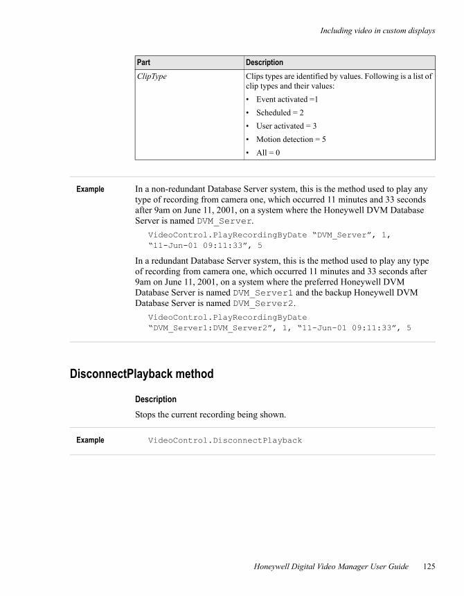
Including video in custom displays
Honeywell Digital Video Manager User Guide 125
Example In a non-redundant Database Server system, this is the method used to play any type of recording from camera one, which occurred 11 minutes and 33 seconds after 9am on June 11, 2001, on a system where the Honeywell DVM Database Server is named DVM_Server.
VideoControl.PlayRecordingByDate “DVM_Server”, 1, “11-Jun-01 09:11:33”, 5
In a redundant Database Server system, this is the method used to play any type of recording from camera one, which occurred 11 minutes and 33 seconds after 9am on June 11, 2001, on a system where the preferred Honeywell DVM Database Server is named DVM_Server1 and the backup Honeywell DVM Database Server is named DVM_Server2.
VideoControl.PlayRecordingByDate “DVM_Server1:DVM_Server2”, 1, “11-Jun-01 09:11:33”, 5
DisconnectPlayback method
DescriptionStops the current recording being shown.
Example VideoControl.DisconnectPlayback
ClipType Clips types are identified by values. Following is a list of clip types and their values:• Event activated =1• Scheduled = 2• User activated = 3• Motion detection = 5• All = 0
Part Description
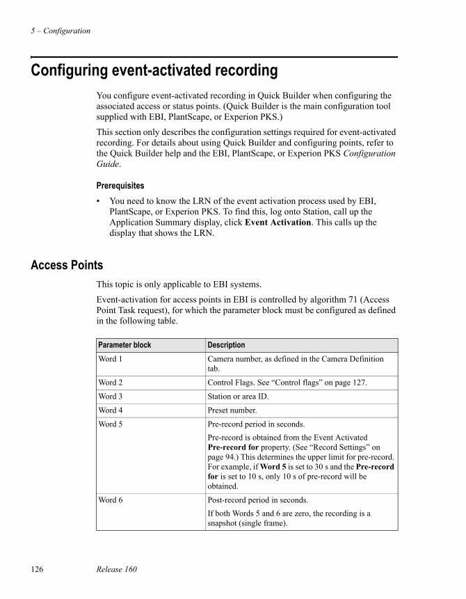
5 – Configuration
126 Release 160
Configuring event-activated recordingYou configure event-activated recording in Quick Builder when configuring the associated access or status points. (Quick Builder is the main configuration tool supplied with EBI, PlantScape, or Experion PKS.)
This section only describes the configuration settings required for event-activated recording. For details about using Quick Builder and configuring points, refer to the Quick Builder help and the EBI, PlantScape, or Experion PKS Configuration Guide.
Prerequisites• You need to know the LRN of the event activation process used by EBI,
PlantScape, or Experion PKS. To find this, log onto Station, call up the Application Summary display, click Event Activation. This calls up the display that shows the LRN.
Access PointsThis topic is only applicable to EBI systems.
Event-activation for access points in EBI is controlled by algorithm 71 (Access Point Task request), for which the parameter block must be configured as defined in the following table.
Parameter block DescriptionWord 1 Camera number, as defined in the Camera Definition
tab.
Word 2 Control Flags. See “Control flags” on page 127.
Word 3 Station or area ID.
Word 4 Preset number.
Word 5 Pre-record period in seconds. Pre-record is obtained from the Event Activated Pre-record for property. (See “Record Settings” on page 94.) This determines the upper limit for pre-record. For example, if Word 5 is set to 30 s and the Pre-record for is set to 10 s, only 10 s of pre-record will be obtained.
Word 6 Post-record period in seconds.If both Words 5 and 6 are zero, the recording is a snapshot (single frame).
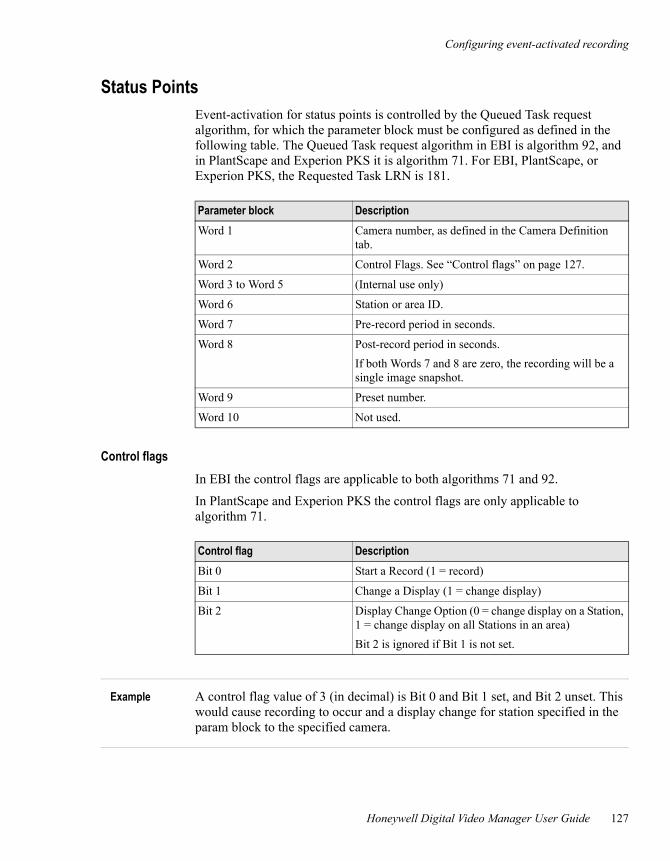
Configuring event-activated recording
Honeywell Digital Video Manager User Guide 127
Status PointsEvent-activation for status points is controlled by the Queued Task request algorithm, for which the parameter block must be configured as defined in the following table. The Queued Task request algorithm in EBI is algorithm 92, and in PlantScape and Experion PKS it is algorithm 71. For EBI, PlantScape, or Experion PKS, the Requested Task LRN is 181.
Control flagsIn EBI the control flags are applicable to both algorithms 71 and 92.
In PlantScape and Experion PKS the control flags are only applicable to algorithm 71.
Example A control flag value of 3 (in decimal) is Bit 0 and Bit 1 set, and Bit 2 unset. This would cause recording to occur and a display change for station specified in the param block to the specified camera.
Parameter block DescriptionWord 1 Camera number, as defined in the Camera Definition
tab.
Word 2 Control Flags. See “Control flags” on page 127.
Word 3 to Word 5 (Internal use only)
Word 6 Station or area ID.
Word 7 Pre-record period in seconds.
Word 8 Post-record period in seconds.If both Words 7 and 8 are zero, the recording will be a single image snapshot.
Word 9 Preset number.
Word 10 Not used.
Control flag DescriptionBit 0 Start a Record (1 = record)
Bit 1 Change a Display (1 = change display)
Bit 2 Display Change Option (0 = change display on a Station, 1 = change display on all Stations in an area)Bit 2 is ignored if Bit 1 is not set.

5 – Configuration
128 Release 160
When an alarm monitor is configured for the station specified in Word 3 (Access Points) or Word 6 (Status Points) and the change display flag is set, the video will be displayed on the alarm monitor.
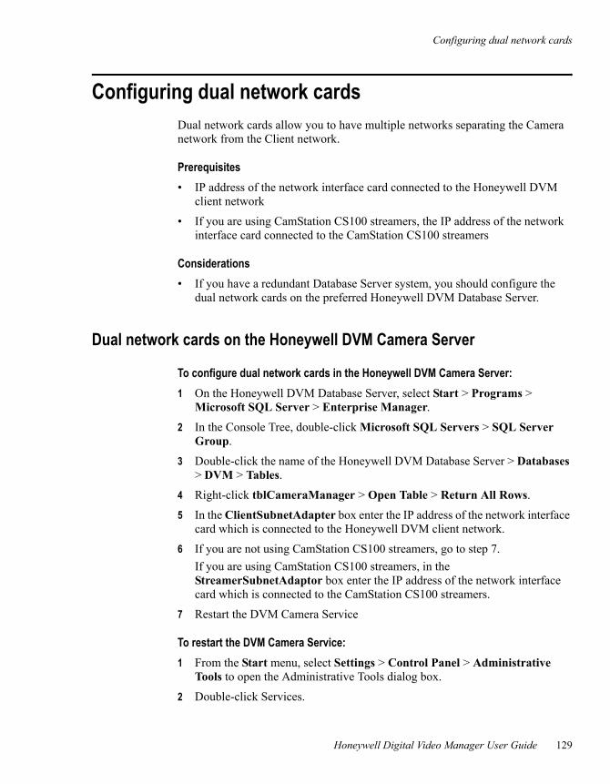
Configuring dual network cards
Honeywell Digital Video Manager User Guide 129
Configuring dual network cardsDual network cards allow you to have multiple networks separating the Camera network from the Client network.
Prerequisites• IP address of the network interface card connected to the Honeywell DVM
client network
• If you are using CamStation CS100 streamers, the IP address of the network interface card connected to the CamStation CS100 streamers
Considerations• If you have a redundant Database Server system, you should configure the
dual network cards on the preferred Honeywell DVM Database Server.
Dual network cards on the Honeywell DVM Camera Server
To configure dual network cards in the Honeywell DVM Camera Server:1 On the Honeywell DVM Database Server, select Start > Programs >
Microsoft SQL Server > Enterprise Manager.
2 In the Console Tree, double-click Microsoft SQL Servers > SQL Server Group.
3 Double-click the name of the Honeywell DVM Database Server > Databases > DVM > Tables.
4 Right-click tblCameraManager > Open Table > Return All Rows.
5 In the ClientSubnetAdapter box enter the IP address of the network interface card which is connected to the Honeywell DVM client network.
6 If you are not using CamStation CS100 streamers, go to step 7.If you are using CamStation CS100 streamers, in the StreamerSubnetAdaptor box enter the IP address of the network interface card which is connected to the CamStation CS100 streamers.
7 Restart the DVM Camera Service
To restart the DVM Camera Service:1 From the Start menu, select Settings > Control Panel > Administrative
Tools to open the Administrative Tools dialog box.
2 Double-click Services.
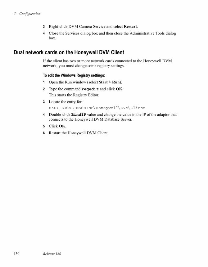
5 – Configuration
130 Release 160
3 Right-click DVM Camera Service and select Restart.
4 Close the Services dialog box and then close the Administrative Tools dialog box.
Dual network cards on the Honeywell DVM ClientIf the client has two or more network cards connected to the Honeywell DVM network, you must change some registry settings.
To edit the Windows Registry settings:1 Open the Run window (select Start > Run).
2 Type the command regedit and click OK.This starts the Registry Editor.
3 Locate the entry for:HKEY_LOCAL_MACHINE\Honeywell\DVM\Client
4 Double-click BindIP value and change the value to the IP of the adaptor that connects to the Honeywell DVM Database Server.
5 Click OK.
6 Restart the Honeywell DVM Client.
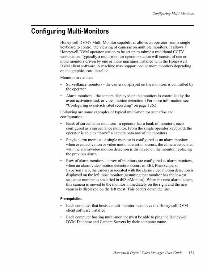
Configuring Multi-Monitors
Honeywell Digital Video Manager User Guide 131
Configuring Multi-MonitorsHoneywell DVM's Multi-Monitor capabilities allows an operator from a single keyboard to control the viewing of cameras on multiple monitors. It allows a Honeywell DVM operator station to be set up to mimic a traditional CCTV workstation. Typically a multi-monitor operator station will consist of one or more monitors driven by one or more machines installed with the Honeywell DVM client software. A machine may support one or more monitors depending on the graphics card installed.
Monitors are either:
• Surveillance monitors - the camera displayed on the monitors is controlled by the operator
• Alarm monitors - the camera displayed on the monitors is controlled by the event activation task or video motion detection. (For more information see “Configuring event-activated recording” on page 126.)
Following are some examples of typical multi-monitor scenarios and configuration:
• Bank of surveillance monitors - a operator has a bank of monitors, each configured as a surveillance monitor. From the single operator keyboard, the operator is able to “throw” a camera onto any of the monitors
• Single alarm monitor - a single monitor is configured as an alarm monitor, when event activation or video motion detection occurs, the camera associated with the alarm/video motion detection is displayed on the monitor, replacing the previous alarm.
• Row of alarm monitors - a row of monitors are configured as alarm monitors, when an alarm/video motion detection occurs in EBI, PlantScape, or Experion PKS, the camera associated with the alarm/video motion detection is displayed on the left most monitor (assuming that monitor has the lowest sequence number as specified in tblStnMonitor). When the next alarm occurs, this camera is moved to the monitor immediately on the right and the new camera is displayed on the left most. This occurs down the line.
Prerequisites• Each computer that hosts a multi-monitor must have the Honeywell DVM
client software installed.
• Each computer hosting multi-monitor must be able to ping the Honeywell DVM Database and Camera Servers by their computer name.
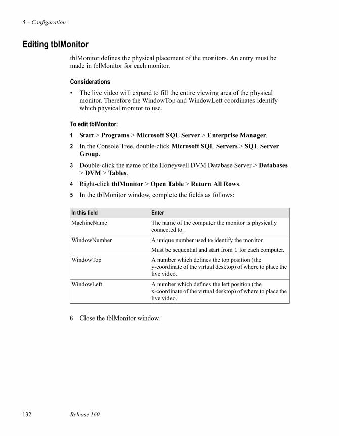
5 – Configuration
132 Release 160
Editing tblMonitortblMonitor defines the physical placement of the monitors. An entry must be made in tblMonitor for each monitor.
Considerations• The live video will expand to fill the entire viewing area of the physical
monitor. Therefore the WindowTop and WindowLeft coordinates identify which physical monitor to use.
To edit tblMonitor:1 Start > Programs > Microsoft SQL Server > Enterprise Manager.
2 In the Console Tree, double-click Microsoft SQL Servers > SQL Server Group.
3 Double-click the name of the Honeywell DVM Database Server > Databases > DVM > Tables.
4 Right-click tblMonitor > Open Table > Return All Rows.
5 In the tblMonitor window, complete the fields as follows:
6 Close the tblMonitor window.
In this field EnterMachineName The name of the computer the monitor is physically
connected to.
WindowNumber A unique number used to identify the monitor. Must be sequential and start from 1 for each computer.
WindowTop A number which defines the top position (the y-coordinate of the virtual desktop) of where to place the live video.
WindowLeft A number which defines the left position (the x-coordinate of the virtual desktop) of where to place the live video.
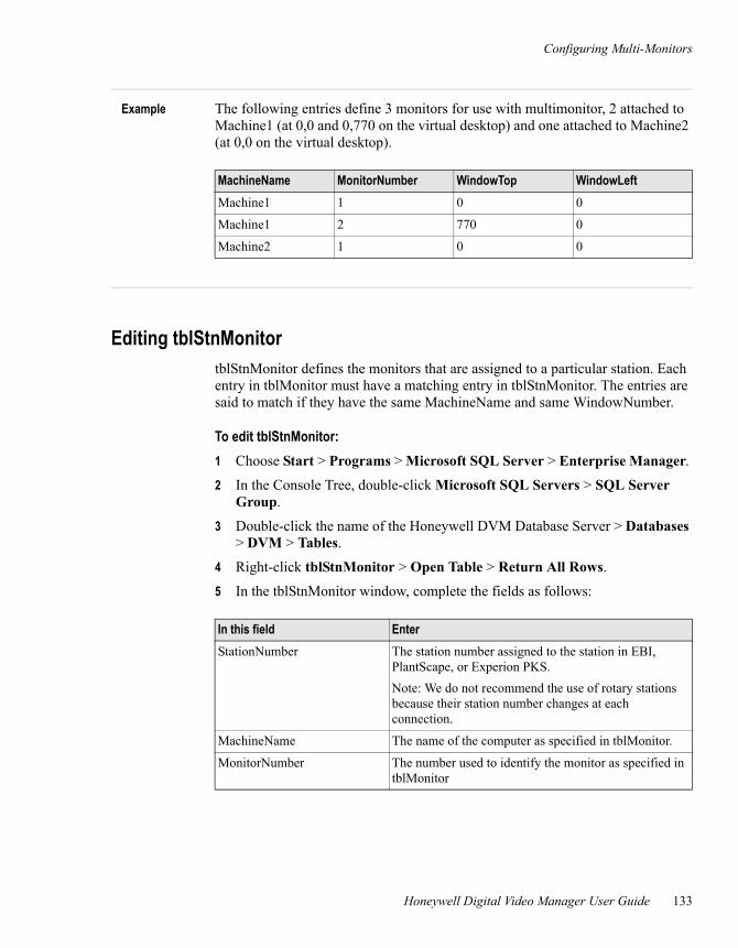
Configuring Multi-Monitors
Honeywell Digital Video Manager User Guide 133
Example The following entries define 3 monitors for use with multimonitor, 2 attached to Machine1 (at 0,0 and 0,770 on the virtual desktop) and one attached to Machine2 (at 0,0 on the virtual desktop).
Editing tblStnMonitortblStnMonitor defines the monitors that are assigned to a particular station. Each entry in tblMonitor must have a matching entry in tblStnMonitor. The entries are said to match if they have the same MachineName and same WindowNumber.
To edit tblStnMonitor:1 Choose Start > Programs > Microsoft SQL Server > Enterprise Manager.
2 In the Console Tree, double-click Microsoft SQL Servers > SQL Server Group.
3 Double-click the name of the Honeywell DVM Database Server > Databases > DVM > Tables.
4 Right-click tblStnMonitor > Open Table > Return All Rows.
5 In the tblStnMonitor window, complete the fields as follows:
MachineName MonitorNumber WindowTop WindowLeftMachine1 1 0 0
Machine1 2 770 0
Machine2 1 0 0
In this field EnterStationNumber The station number assigned to the station in EBI,
PlantScape, or Experion PKS.Note: We do not recommend the use of rotary stations because their station number changes at each connection.
MachineName The name of the computer as specified in tblMonitor.
MonitorNumber The number used to identify the monitor as specified in tblMonitor
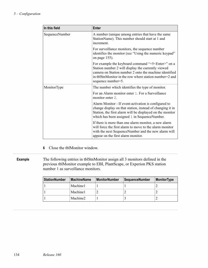
5 – Configuration
134 Release 160
6 Close the tblMonitor window.
Example The following entries in tblStnMonitor assign all 3 monitors defined in the previous tblMonitor example to EBI, PlantScape, or Experion PKS station number 1 as surveillance monitors.
SequenceNumber A number (unique among entries that have the same StationName). This number should start at 1 and increment. For surveillance monitors, the sequence number identifies the monitor (see “Using the numeric keypad” on page 155). For example the keyboard command “+5<Enter>” on a Station number 2 will display the currently viewed camera on Station number 2 onto the machine identified in tblStnMonitor in the row where station number=2 and sequence number=5.
MonitorType The number which identifies the type of monitor. For an Alarm monitor enter 1. For a Surveillance monitor enter 2.Alarm Monitor - If event-activation is configured to change display on that station, instead of changing it in Station, the first alarm will be displayed on the monitor which has been assigned 1 in SequenceNumber. If there is more than one alarm monitor, a new alarm will force the first alarm to move to the alarm monitor with the next SequenceNumber and the new alarm will appear on the first alarm monitor.
In this field Enter
StationNumber MachineName MonitorNumber SequenceNumber MonitorType1 Machine1 1 1 2
1 Machine1 2 2 2
1 Machine2 1 3 2
Configuring the audit log
Honeywell Digital Video Manager User Guide 135
Configuring the audit log To provide an audit trail, Honeywell DVM keeps a log of all user actions and system events. The audit log is stored in the Honeywell DVM database.
The events which are logged are not configurable, however the length of time events are kept for is configurable.
The size of the audit log depends on how often events are generated and the length of time they are kept for. To avoid using unnecessary disk space, events should only be kept for as long as is necessary. A recommended setting is 1 week or 1 month.
To configure the audit log: 1 Click Audit Log in the Navigation Pane.
2 Enter the length of time to keep the audit events for.
At approximately midnight this value is checked and any audit events that are older than the period specified are deleted.
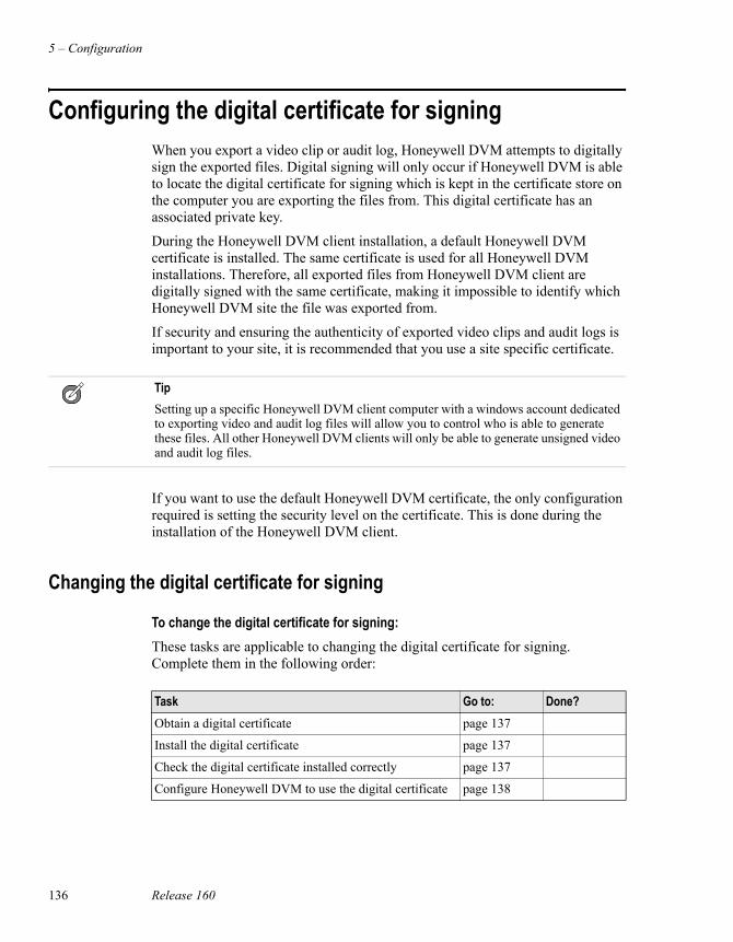
5 – Configuration
136 Release 160
Configuring the digital certificate for signingWhen you export a video clip or audit log, Honeywell DVM attempts to digitally sign the exported files. Digital signing will only occur if Honeywell DVM is able to locate the digital certificate for signing which is kept in the certificate store on the computer you are exporting the files from. This digital certificate has an associated private key.
During the Honeywell DVM client installation, a default Honeywell DVM certificate is installed. The same certificate is used for all Honeywell DVM installations. Therefore, all exported files from Honeywell DVM client are digitally signed with the same certificate, making it impossible to identify which Honeywell DVM site the file was exported from.
If security and ensuring the authenticity of exported video clips and audit logs is important to your site, it is recommended that you use a site specific certificate.
If you want to use the default Honeywell DVM certificate, the only configuration required is setting the security level on the certificate. This is done during the installation of the Honeywell DVM client.
Changing the digital certificate for signing
To change the digital certificate for signing:These tasks are applicable to changing the digital certificate for signing. Complete them in the following order:
TipSetting up a specific Honeywell DVM client computer with a windows account dedicated to exporting video and audit log files will allow you to control who is able to generate these files. All other Honeywell DVM clients will only be able to generate unsigned video and audit log files.
Task Go to: Done?Obtain a digital certificate page 137
Install the digital certificate page 137
Check the digital certificate installed correctly page 137
Configure Honeywell DVM to use the digital certificate page 138
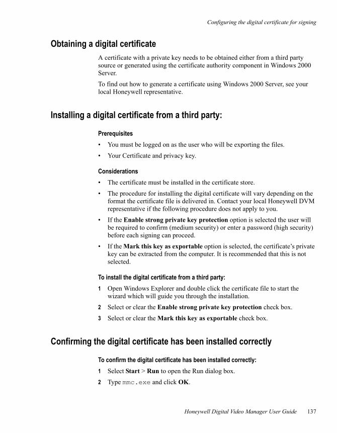
Configuring the digital certificate for signing
Honeywell Digital Video Manager User Guide 137
Obtaining a digital certificateA certificate with a private key needs to be obtained either from a third party source or generated using the certificate authority component in Windows 2000 Server.
To find out how to generate a certificate using Windows 2000 Server, see your local Honeywell representative.
Installing a digital certificate from a third party:
Prerequisites• You must be logged on as the user who will be exporting the files.
• Your Certificate and privacy key.
Considerations• The certificate must be installed in the certificate store.
• The procedure for installing the digital certificate will vary depending on the format the certificate file is delivered in. Contact your local Honeywell DVM representative if the following procedure does not apply to you.
• If the Enable strong private key protection option is selected the user will be required to confirm (medium security) or enter a password (high security) before each signing can proceed.
• If the Mark this key as exportable option is selected, the certificate’s private key can be extracted from the computer. It is recommended that this is not selected.
To install the digital certificate from a third party:1 Open Windows Explorer and double click the certificate file to start the
wizard which will guide you through the installation.
2 Select or clear the Enable strong private key protection check box.
3 Select or clear the Mark this key as exportable check box.
Confirming the digital certificate has been installed correctly
To confirm the digital certificate has been installed correctly:1 Select Start > Run to open the Run dialog box.
2 Type mmc.exe and click OK.
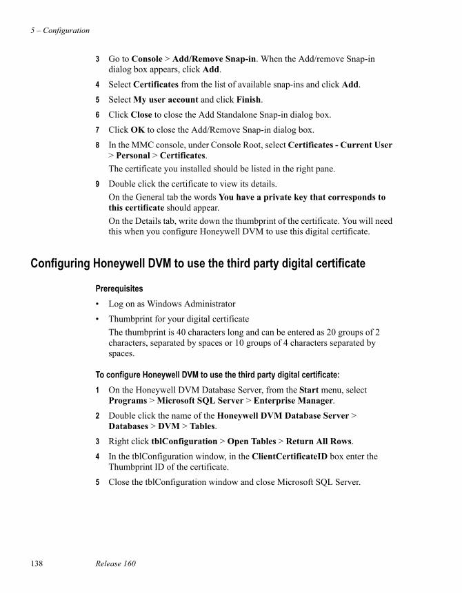
5 – Configuration
138 Release 160
3 Go to Console > Add/Remove Snap-in. When the Add/remove Snap-in dialog box appears, click Add.
4 Select Certificates from the list of available snap-ins and click Add.
5 Select My user account and click Finish.
6 Click Close to close the Add Standalone Snap-in dialog box.
7 Click OK to close the Add/Remove Snap-in dialog box.
8 In the MMC console, under Console Root, select Certificates - Current User > Personal > Certificates.The certificate you installed should be listed in the right pane.
9 Double click the certificate to view its details.On the General tab the words You have a private key that corresponds to this certificate should appear.On the Details tab, write down the thumbprint of the certificate. You will need this when you configure Honeywell DVM to use this digital certificate.
Configuring Honeywell DVM to use the third party digital certificate
Prerequisites• Log on as Windows Administrator
• Thumbprint for your digital certificateThe thumbprint is 40 characters long and can be entered as 20 groups of 2 characters, separated by spaces or 10 groups of 4 characters separated by spaces.
To configure Honeywell DVM to use the third party digital certificate:1 On the Honeywell DVM Database Server, from the Start menu, select
Programs > Microsoft SQL Server > Enterprise Manager.
2 Double click the name of the Honeywell DVM Database Server > Databases > DVM > Tables.
3 Right click tblConfiguration > Open Tables > Return All Rows.
4 In the tblConfiguration window, in the ClientCertificateID box enter the Thumbprint ID of the certificate.
5 Close the tblConfiguration window and close Microsoft SQL Server.
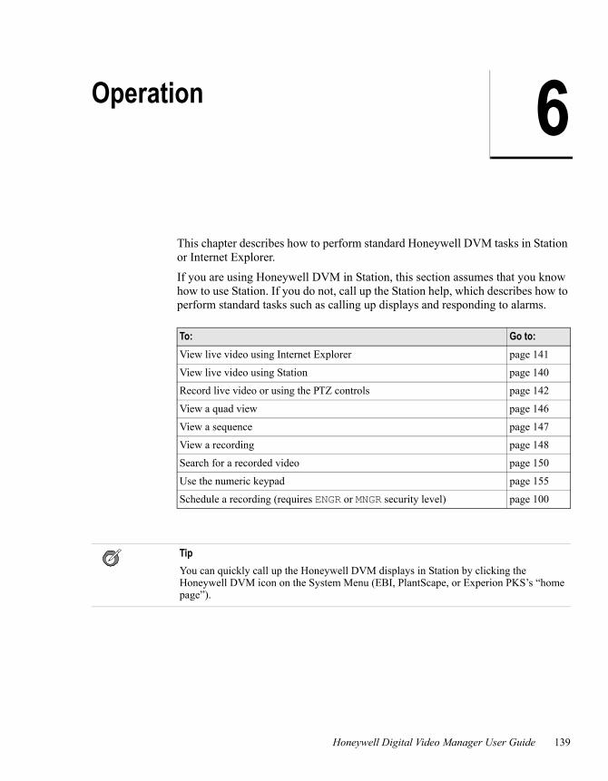
Honeywell Digital Video Manager User Guide 139
6Operation
This chapter describes how to perform standard Honeywell DVM tasks in Station or Internet Explorer.
If you are using Honeywell DVM in Station, this section assumes that you know how to use Station. If you do not, call up the Station help, which describes how to perform standard tasks such as calling up displays and responding to alarms.
To: Go to:View live video using Internet Explorer page 141
View live video using Station page 140
Record live video or using the PTZ controls page 142
View a quad view page 146
View a sequence page 147
View a recording page 148
Search for a recorded video page 150
Use the numeric keypad page 155
Schedule a recording (requires ENGR or MNGR security level) page 100
TipYou can quickly call up the Honeywell DVM displays in Station by clicking the Honeywell DVM icon on the System Menu (EBI, PlantScape, or Experion PKS’s “home page”).
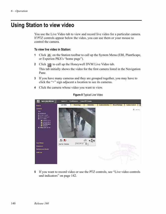
6 – Operation
140 Release 160
Using Station to view videoYou use the Live Video tab to view and record live video for a particular camera. If PTZ controls appear below the video, you can use them or your mouse to control the camera.
To view live video in Station:1 Click on the Station toolbar to call up the System Menu (EBI, PlantScape,
or Experion PKS’s “home page”).
2 Click to call up the Honeywell DVM Live Video tab.This tab initially shows the video for the first camera listed in the Navigation Pane.
3 If you have many cameras and they are grouped together, you may have to click the “+” sign adjacent a location to see its cameras.
4 Click the camera whose video you want to view.
5 If you want to record video or use the PTZ controls, see “Live video controls and indicators” on page 142.
Figure 8 Typical Live Video
Using Internet Explorer to view video
Honeywell Digital Video Manager User Guide 141
Using Internet Explorer to view videoYou can use Internet Explorer to view video instead of Station.
Prerequisites• Internet Explorer security has been configured by your administrator. See
“Internet Explorer security” on page 160.
Considerations• If the users security level is changed in the Honeywell DVM Database Server
when the user is viewing Honeywell DVM pages in Internet Explorer, the pages will not update until the page has been refreshed.
To view video using Internet Explorer:1 Log on to your computer.
2 Start Internet Explorer and enter the URL http://machinename/dvmWhere machinename is the name of the Honeywell DVM Database Server. If you have a redundant Database Server system, machinename is the name of the preferred Honeywell DVM Database Server.The Honeywell DVM Live Video tab appears. This tab initially shows the video for the first camera listed in the Navigation Pane.
3 If you have many cameras and they are grouped together, you may have to click the “+” sign adjacent a location to see its cameras.
4 Click the camera whose video you want to view.
5 If you want to record video or use the PTZ controls, see “Live video controls and indicators” on page 142.
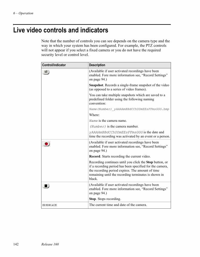
6 – Operation
142 Release 160
Live video controls and indicatorsNote that the number of controls you can see depends on the camera type and the way in which your system has been configured. For example, the PTZ controls will not appear if you select a fixed camera or you do not have the required security level or control level.
Control/indicator Description(Available if user activated recordings have been enabled. Fore more information see, “Record Settings” on page 94.)Snapshot. Records a single-frame snapshot of the video (as opposed to a series of video frames).You can take multiple snapshots which are saved to a predefined folder using the following naming convention:Name(Number)_yAAAAmBBdCChDDmEEsFFmsGGG.bmp
Where:Name is the camera name.(Number) is the camera number.yAAAAmBBdCChDDmEEsFFmsGGG is the date and time the recording was activated by an event or a person.
(Available if user activated recordings have been enabled. Fore more information see, “Record Settings” on page 94.)Record. Starts recording the current video.Recording continues until you click the Stop button, or if a recording period has been specified for the camera, the recording period expires. The amount of time remaining until the recording terminates is shown in black.
(Available if user activated recordings have been enabled. Fore more information see, “Record Settings” on page 94.)Stop. Stops recording.
The current time and date of the camera.
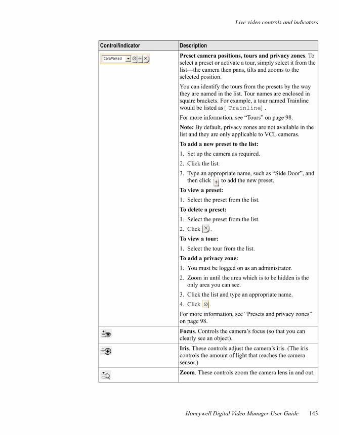
Live video controls and indicators
Honeywell Digital Video Manager User Guide 143
Preset camera positions, tours and privacy zones. To select a preset or activate a tour, simply select it from the list—the camera then pans, tilts and zooms to the selected position. You can identify the tours from the presets by the way they are named in the list. Tour names are enclosed in square brackets. For example, a tour named Trainline would be listed as [Trainline]. For more information, see “Tours” on page 98.Note: By default, privacy zones are not available in the list and they are only applicable to VCL cameras.To add a new preset to the list: 1. Set up the camera as required.2. Click the list.3. Type an appropriate name, such as “Side Door”, and
then click to add the new preset.To view a preset: 1. Select the preset from the list.To delete a preset: 1. Select the preset from the list.2. Click .To view a tour:1. Select the tour from the list. To add a privacy zone: 1. You must be logged on as an administrator.2. Zoom in until the area which is to be hidden is the
only area you can see.3. Click the list and type an appropriate name.4. Click .For more information, see “Presets and privacy zones” on page 98.
Focus. Controls the camera’s focus (so that you can clearly see an object).
Iris. These controls adjust the camera’s iris. (The iris controls the amount of light that reaches the camera sensor.)
Zoom. These controls zoom the camera lens in and out.
Control/indicator Description
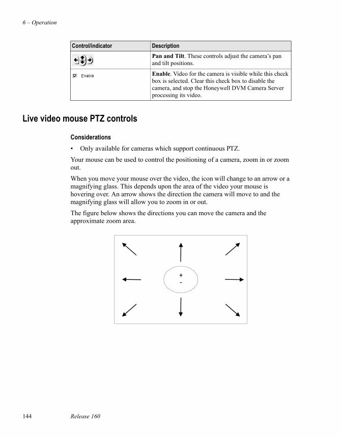
6 – Operation
144 Release 160
Live video mouse PTZ controls
Considerations• Only available for cameras which support continuous PTZ.
Your mouse can be used to control the positioning of a camera, zoom in or zoom out.
When you move your mouse over the video, the icon will change to an arrow or a magnifying glass. This depends upon the area of the video your mouse is hovering over. An arrow shows the direction the camera will move to and the magnifying glass will allow you to zoom in or out.
The figure below shows the directions you can move the camera and the approximate zoom area.
Pan and Tilt. These controls adjust the camera’s pan and tilt positions.
Enable. Video for the camera is visible while this check box is selected. Clear this check box to disable the camera, and stop the Honeywell DVM Camera Server processing its video.
Control/indicator Description
+-
Live video controls and indicators
Honeywell Digital Video Manager User Guide 145
Controlling the camera movementTo control the movement of the camera with your mouse, move it over the video until you see the icon change to an arrow. There are two methods which can be used to move the camera. They are:
• A single click will move the camera in the direction of the arrow.
• Hold down the left mouse key and drag the mouse in the direction you want the camera to move to.
How fast the camera moves, depends on where you click in relation to the centre of the video. The closer you are to the edge of the video, the faster the movement of the camera.
Zooming inTo zoom in, move your mouse just above the centre of the video. When the magnifying glass appears with a “+”, click your left mouse key.
To continuously zoom in, hold down your left mouse key. To increase the speed of the zoom, drag the icon towards the top of the video and to decrease the speed drag back towards the centre of the video.
Zooming outTo zoom out, move your mouse just below the centre of the video. When the magnifying glass appears with a “-”, click your left mouse key.
To continuously zoom out, hold down your left mouse key. To increase the speed of the zoom, drag the icon towards the bottom of the video and to decrease the speed drag towards the centre of the video.
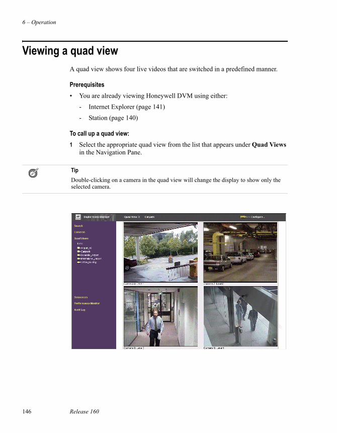
6 – Operation
146 Release 160
Viewing a quad viewA quad view shows four live videos that are switched in a predefined manner.
Prerequisites• You are already viewing Honeywell DVM using either:
- Internet Explorer (page 141)
- Station (page 140)
To call up a quad view:1 Select the appropriate quad view from the list that appears under Quad Views
in the Navigation Pane.
TipDouble-clicking on a camera in the quad view will change the display to show only the selected camera.
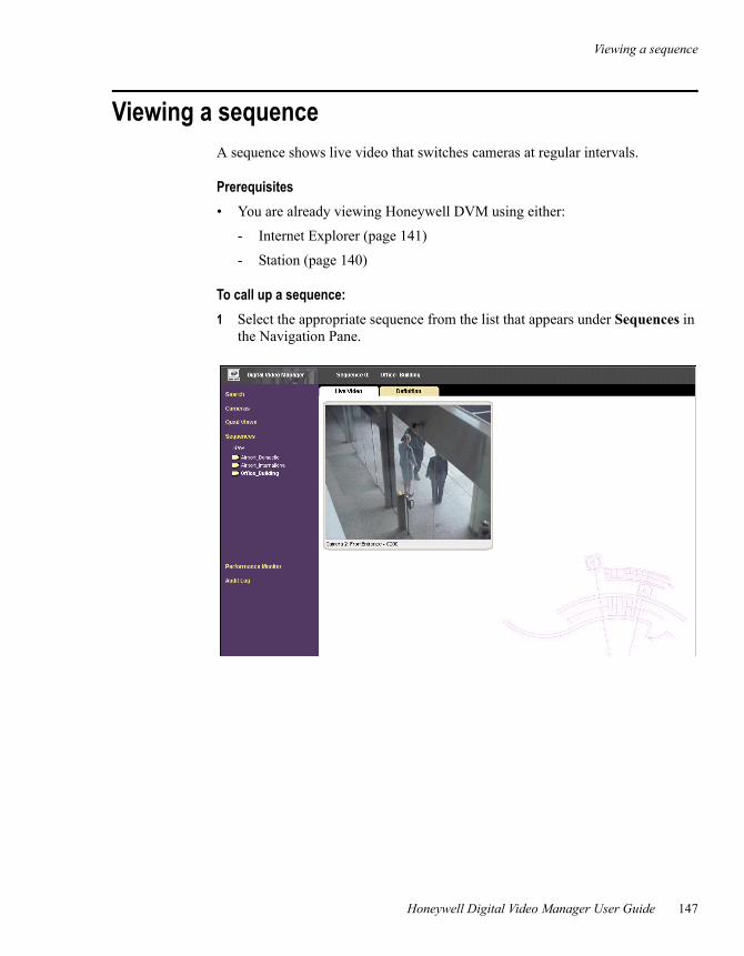
Viewing a sequence
Honeywell Digital Video Manager User Guide 147
Viewing a sequenceA sequence shows live video that switches cameras at regular intervals.
Prerequisites• You are already viewing Honeywell DVM using either:
- Internet Explorer (page 141)
- Station (page 140)
To call up a sequence:1 Select the appropriate sequence from the list that appears under Sequences in
the Navigation Pane.
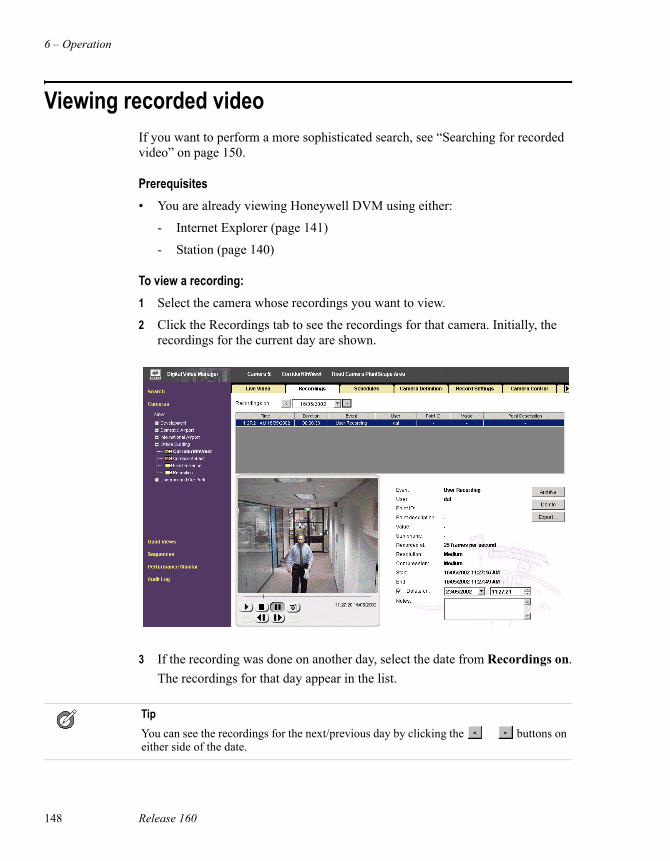
6 – Operation
148 Release 160
Viewing recorded videoIf you want to perform a more sophisticated search, see “Searching for recorded video” on page 150.
Prerequisites• You are already viewing Honeywell DVM using either:
- Internet Explorer (page 141)
- Station (page 140)
To view a recording:1 Select the camera whose recordings you want to view.
2 Click the Recordings tab to see the recordings for that camera. Initially, the recordings for the current day are shown.
3 If the recording was done on another day, select the date from Recordings on.The recordings for that day appear in the list.
TipYou can see the recordings for the next/previous day by clicking the buttons on either side of the date.
Viewing recorded video
Honeywell Digital Video Manager User Guide 149
4 Select a video clip from the list to see its first frame in the video player. You can use the player controls to check that you have selected the correct video.If the video clip selected had pre-record defined, the frame shown is the frame which was recorded when the operator pressed record or the EBI, PlantScape, or Experion PKS event occurred, not the first frame of the recording.
5 You can also:
• Type any relevant comments in Notes. (Adding a note can be useful because you can use the notes to retrieve the video clip—see “Doing an advanced search” on page 151.)
• Delete it immediately by clicking the Delete button, or change the default deletion instructions by changing the Delete on values.
• Take a snapshot of part of the video clip by clicking . For more information, see “Live video controls and indicators” on page 142.
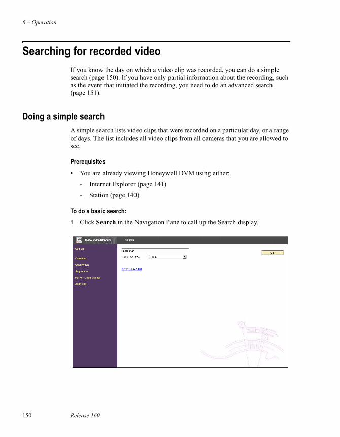
6 – Operation
150 Release 160
Searching for recorded videoIf you know the day on which a video clip was recorded, you can do a simple search (page 150). If you have only partial information about the recording, such as the event that initiated the recording, you need to do an advanced search (page 151).
Doing a simple searchA simple search lists video clips that were recorded on a particular day, or a range of days. The list includes all video clips from all cameras that you are allowed to see.
Prerequisites• You are already viewing Honeywell DVM using either:
- Internet Explorer (page 141)
- Station (page 140)
To do a basic search:1 Click Search in the Navigation Pane to call up the Search display.
Searching for recorded video
Honeywell Digital Video Manager User Guide 151
2 Select the day/range you want to search, as described in the following table and then click Go.
3 See “Viewing the search results” on page 154.
Doing an advanced searchAn advanced search allows you to specify a wide range of search criteria including camera ID, point ID, and event priority.
Prerequisites• You are already viewing Honeywell DVM using either:
- Internet Explorer (page 141)
- Station (page 140)
To do an advanced search:1 Click Search in the Navigation Pane to call up the Search display.
2 Click Advanced Search.
Select this: To find videos that were recorded:Today Today, starting from midnight.
Yesterday Yesterday, from midnight to midnight.
Last Week For the last 7 days, from midnight to midnight.
Last Month From the same calender date last month until today. For example, if today is the August 13, the videos will be from July 13 to August 13.
On A particular day. You must select the date from a calendar.
On or before On or before a specific date. You must select the date from a calendar.
Between A range of dates. You must select the start and end dates from a calendar.
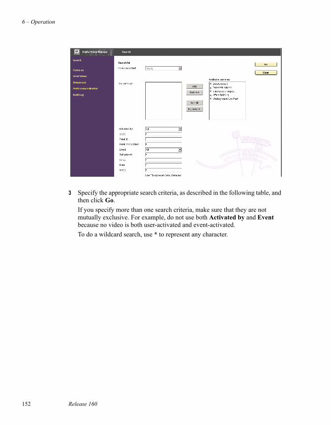
6 – Operation
152 Release 160
3 Specify the appropriate search criteria, as described in the following table, and then click Go.If you specify more than one search criteria, make sure that they are not mutually exclusive. For example, do not use both Activated by and Event because no video is both user-activated and event-activated.To do a wildcard search, use * to represent any character.
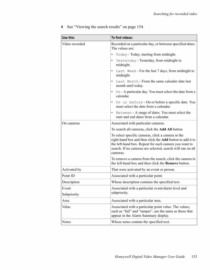
Searching for recorded video
Honeywell Digital Video Manager User Guide 153
4 See “Viewing the search results” on page 154.
Use this: To find videos:Video recorded Recorded on a particular day, or between specified dates.
The values are:• Today - Today, starting from midnight.• Yesterday - Yesterday, from midnight to
midnight.• Last Week - For the last 7 days, from midnight to
midnight.• Last Month - From the same calender date last
month until today.• On - A particular day. You must select the date from a
calendar.• On or before - On or before a specific date. You
must select the date from a calendar.• Between - A range of dates. You must select the
start and end dates from a calendar.
On cameras Associated with particular cameras.To search all cameras, click the Add All button.To select specific cameras, click a camera in the right-hand box and then click the Add button to add it to the left-hand box. Repeat for each camera you want to search. If no cameras are selected, search will run on all cameras.To remove a camera from the search, click the camera in the left-hand box and then click the Remove button.
Activated by That were activated by an event or person.
Point ID Associated with a particular point.
Description Whose description contains the specified text.
EventSubpriority
Associated with a particular event/alarm level and subpriority.
Area Associated with a particular area.
Value Associated with a particular point value. The values, such as “fail” and “tamper”, are the same as those that appear in the Alarm Summary display.
Notes Whose notes contain the specified text.
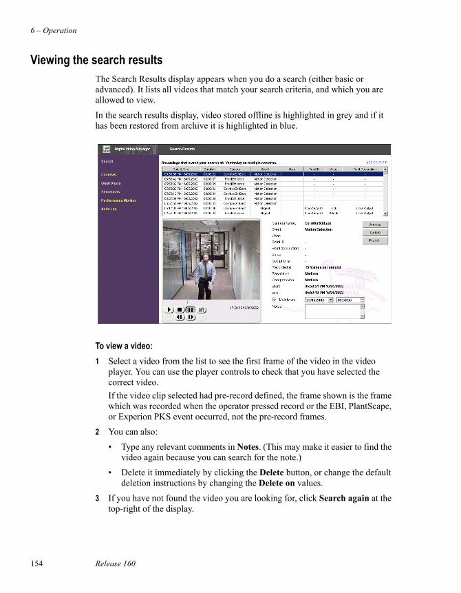
6 – Operation
154 Release 160
Viewing the search resultsThe Search Results display appears when you do a search (either basic or advanced). It lists all videos that match your search criteria, and which you are allowed to view.
In the search results display, video stored offline is highlighted in grey and if it has been restored from archive it is highlighted in blue.
To view a video:1 Select a video from the list to see the first frame of the video in the video
player. You can use the player controls to check that you have selected the correct video.If the video clip selected had pre-record defined, the frame shown is the frame which was recorded when the operator pressed record or the EBI, PlantScape, or Experion PKS event occurred, not the pre-record frames.
2 You can also:
• Type any relevant comments in Notes. (This may make it easier to find the video again because you can search for the note.)
• Delete it immediately by clicking the Delete button, or change the default deletion instructions by changing the Delete on values.
3 If you have not found the video you are looking for, click Search again at the top-right of the display.
Using the numeric keypad
Honeywell Digital Video Manager User Guide 155
Using the numeric keypadConsiderations• Make sure Num Lock is turned on before entering commands using the
numeric keypad.
When you become familiar with Honeywell DVM, you can use the numeric keypad to quickly perform many operations. For example, to call up camera 7 on monitor 3, you would use the following key sequence:
7 + 3 Enter(This is shorthand for typing the camera number, pressing the “+” key, typing the monitor number and then pressing the Enter key.)
The following table describes the purpose of the “command” keys.
More examplesCall up camera 27 on monitor 3:
27 + 3 EnterCall up camera 17, preset 2 on the main monitor:
17 . 2 EnterCall up camera 27, preset 2 on monitor 3:
27 . 2 + 3 Enter
To: Press: Example:Specify camera n n Call up camera 7 on the main monitor:
7 EnterSpecify preset n . n Call up preset 2 for the current camera on the main
monitor:
. 2 EnterSpecify monitor n + n Call up camera 5 on monitor 3:
5 + 3 EnterClear/acknowledge a video on monitor n
- n Clear the video on monitor 3:
-3 EnterSpecify a quad view n
* n Call up quad view 5 on the main monitor:
*5 EnterSpecify a sequence n / n Call up sequence 2 on the main monitor
/2 Enter

6 – Operation
156 Release 160
Call up quad view 4 on monitor 3:* 4 + 3 Enter
Call up sequence 2 on monitor 3:/ 2 + 3 Enter
Honeywell Digital Video Manager User Guide 157
7Administration
This chapter describes administrative tasks.
To: Go to:Configure security page 158
Exporting video and audit logs
Export video page 165
Export the audit log page 166
Archive or restore clips page 171
View or change Honeywell DVM Database Server status (requires ENGR or MNGR security level)
page 173
Changing the Honeywell DVM licence page 174
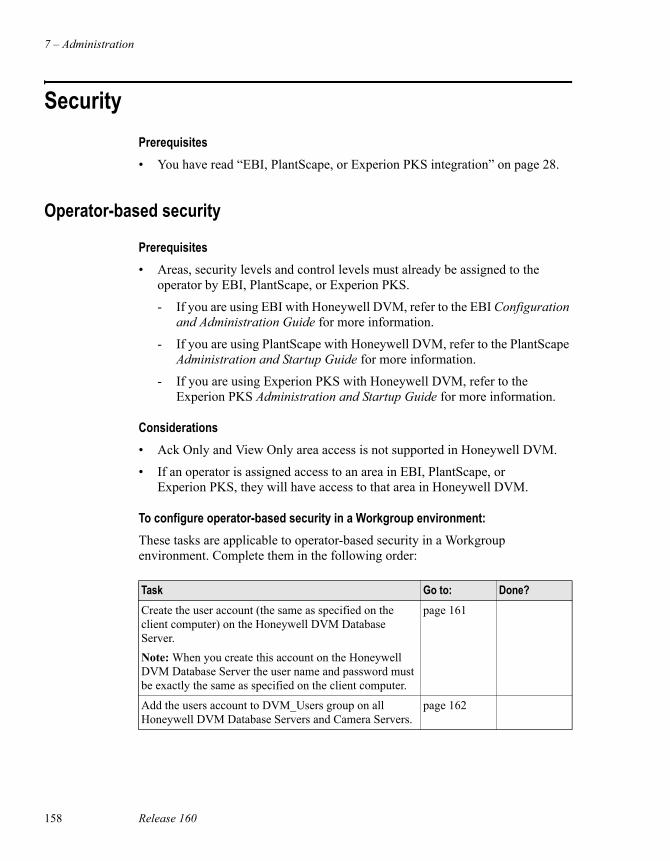
7 – Administration
158 Release 160
SecurityPrerequisites• You have read “EBI, PlantScape, or Experion PKS integration” on page 28.
Operator-based security
Prerequisites• Areas, security levels and control levels must already be assigned to the
operator by EBI, PlantScape, or Experion PKS.
- If you are using EBI with Honeywell DVM, refer to the EBI Configuration and Administration Guide for more information.
- If you are using PlantScape with Honeywell DVM, refer to the PlantScape Administration and Startup Guide for more information.
- If you are using Experion PKS with Honeywell DVM, refer to the Experion PKS Administration and Startup Guide for more information.
Considerations• Ack Only and View Only area access is not supported in Honeywell DVM.
• If an operator is assigned access to an area in EBI, PlantScape, or Experion PKS, they will have access to that area in Honeywell DVM.
To configure operator-based security in a Workgroup environment:These tasks are applicable to operator-based security in a Workgroup environment. Complete them in the following order:
Task Go to: Done?Create the user account (the same as specified on the client computer) on the Honeywell DVM Database Server. Note: When you create this account on the Honeywell DVM Database Server the user name and password must be exactly the same as specified on the client computer.
page 161
Add the users account to DVM_Users group on all Honeywell DVM Database Servers and Camera Servers.
page 162
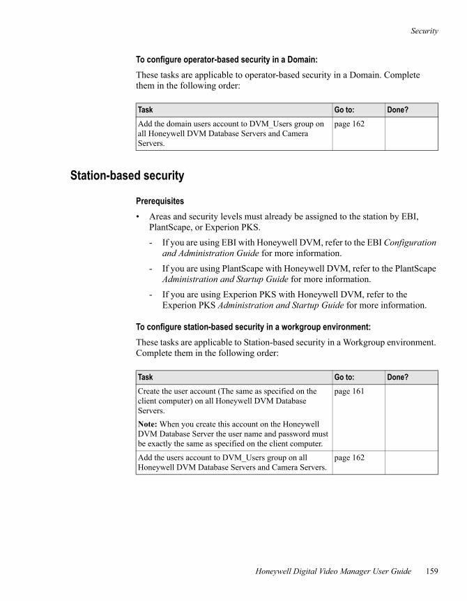
Security
Honeywell Digital Video Manager User Guide 159
To configure operator-based security in a Domain:These tasks are applicable to operator-based security in a Domain. Complete them in the following order:
Station-based security
Prerequisites• Areas and security levels must already be assigned to the station by EBI,
PlantScape, or Experion PKS.
- If you are using EBI with Honeywell DVM, refer to the EBI Configuration and Administration Guide for more information.
- If you are using PlantScape with Honeywell DVM, refer to the PlantScape Administration and Startup Guide for more information.
- If you are using Experion PKS with Honeywell DVM, refer to the Experion PKS Administration and Startup Guide for more information.
To configure station-based security in a workgroup environment:These tasks are applicable to Station-based security in a Workgroup environment. Complete them in the following order:
Task Go to: Done?Add the domain users account to DVM_Users group on all Honeywell DVM Database Servers and Camera Servers.
page 162
Task Go to: Done?Create the user account (The same as specified on the client computer) on all Honeywell DVM Database Servers. Note: When you create this account on the Honeywell DVM Database Server the user name and password must be exactly the same as specified on the client computer.
page 161
Add the users account to DVM_Users group on all Honeywell DVM Database Servers and Camera Servers.
page 162
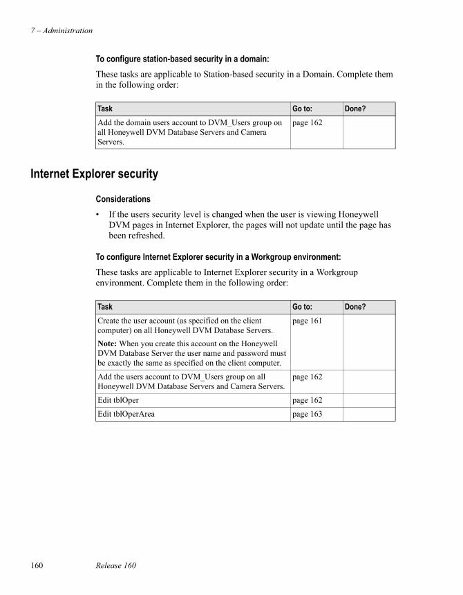
7 – Administration
160 Release 160
To configure station-based security in a domain:These tasks are applicable to Station-based security in a Domain. Complete them in the following order:
Internet Explorer security
Considerations• If the users security level is changed when the user is viewing Honeywell
DVM pages in Internet Explorer, the pages will not update until the page has been refreshed.
To configure Internet Explorer security in a Workgroup environment:These tasks are applicable to Internet Explorer security in a Workgroup environment. Complete them in the following order:
Task Go to: Done?Add the domain users account to DVM_Users group on all Honeywell DVM Database Servers and Camera Servers.
page 162
Task Go to: Done?Create the user account (as specified on the client computer) on all Honeywell DVM Database Servers. Note: When you create this account on the Honeywell DVM Database Server the user name and password must be exactly the same as specified on the client computer.
page 161
Add the users account to DVM_Users group on all Honeywell DVM Database Servers and Camera Servers.
page 162
Edit tblOper page 162
Edit tblOperArea page 163
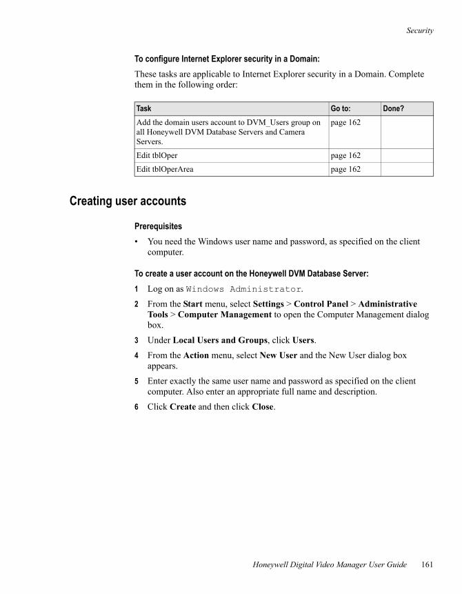
Security
Honeywell Digital Video Manager User Guide 161
To configure Internet Explorer security in a Domain:These tasks are applicable to Internet Explorer security in a Domain. Complete them in the following order:
Creating user accounts
Prerequisites• You need the Windows user name and password, as specified on the client
computer.
To create a user account on the Honeywell DVM Database Server: 1 Log on as Windows Administrator.
2 From the Start menu, select Settings > Control Panel > Administrative Tools > Computer Management to open the Computer Management dialog box.
3 Under Local Users and Groups, click Users.
4 From the Action menu, select New User and the New User dialog box appears.
5 Enter exactly the same user name and password as specified on the client computer. Also enter an appropriate full name and description.
6 Click Create and then click Close.
Task Go to: Done?Add the domain users account to DVM_Users group on all Honeywell DVM Database Servers and Camera Servers.
page 162
Edit tblOper page 162
Edit tblOperArea page 162
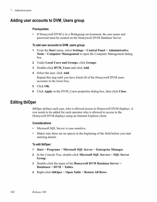
7 – Administration
162 Release 160
Adding user accounts to DVM_Users group
Prerequisites• If Honeywell DVM is in a Workgroup environment, the user name and
password must be created on the Honeywell DVM Database Server.
To add user accounts to DVM_users group:1 From the Start menu, select Settings > Control Panel > Administrative
Tools > Computer Management to open the Computer Management dialog box.
2 Under Local Users and Groups, click Groups.
3 Double-click DVM_Users and click Add.
4 Select the user, click Add. Repeat this step until you have listed all of the Honeywell DVM users accounts in the lower box.
5 Click OK.
6 Click Apply in the DVM_Users properties dialog box, then click Close.
Editing tblOpertblOper defines each user, who is allowed access to Honeywell DVM displays. A row needs to be added for each operator who is allowed to access to the Honeywell DVM displays using an Internet Explorer client.
Considerations• Microsoft SQL Server is case sensitive.
• Maker sure there are no spaces at the beginning of the field before you start entering details.
To edit tblOper:1 Start > Programs > Microsoft SQL Server > Enterprise Manager.
2 In the Console Tree, double-click Microsoft SQL Servers > SQL Server Group.
3 Double-click the name of the Honeywell DVM Database Server > Databases > DVM > Tables.
4 Right-click tblOper > Open Table > Return All Rows.
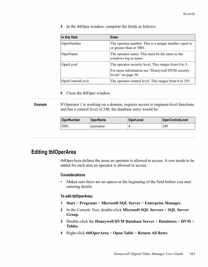
Security
Honeywell Digital Video Manager User Guide 163
5 In the tblOper window, complete the fields as follows:
6 Close the tblOper window.
Example If Operator 1 is working on a domain, requires access to engineer-level functions and has a control level of 240, the database entry would be:
Editing tblOperAreatblOperArea defines the areas an operator is allowed to access. A row needs to be added for each area an operator is allowed to access.
Considerations• Maker sure there are no spaces at the beginning of the field before you start
entering details.
To edit tblOperArea:1 Start > Programs > Microsoft SQL Server > Enterprise Manager.
2 In the Console Tree, double-click Microsoft SQL Servers > SQL Server Group.
3 Double-click the Honeywell DVM Database Server > Databases > DVM > Tables.
4 Right-click tblOperArea > Open Table > Return All Rows.
In this field EnterOperNumber The operator number. This is a unique number equal to
or greater than or 5001.
OperName The operator name. This must be the same as the windows log in name.
OperLevel The operator security level. This ranges from 0 to 5.For more information see “Honeywell DVM security levels” on page 30.
OperControlLevel The operator control level. This ranges from 0 to 255.
OperNumber OperName OperLevel OperControlLevel5001 username 4 240
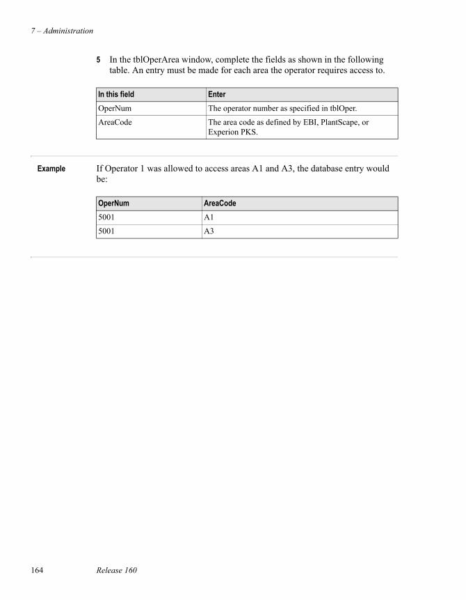
7 – Administration
164 Release 160
5 In the tblOperArea window, complete the fields as shown in the following table. An entry must be made for each area the operator requires access to.
Example If Operator 1 was allowed to access areas A1 and A3, the database entry would be:
In this field EnterOperNum The operator number as specified in tblOper.
AreaCode The area code as defined by EBI, PlantScape, or Experion PKS.
OperNum AreaCode5001 A1
5001 A3
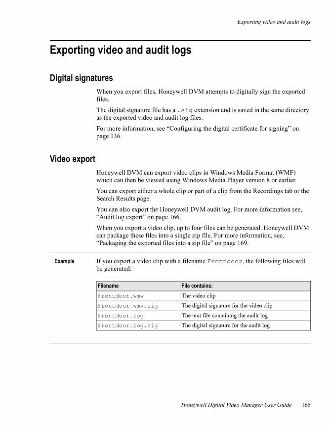
Exporting video and audit logs
Honeywell Digital Video Manager User Guide 165
Exporting video and audit logs
Digital signaturesWhen you export files, Honeywell DVM attempts to digitally sign the exported files.
The digital signature file has a .sig extension and is saved in the same directory as the exported video and audit log files.
For more information, see “Configuring the digital certificate for signing” on page 136.
Video exportHoneywell DVM can export video clips in Windows Media Format (WMF) which can then be viewed using Windows Media Player version 8 or earlier.
You can export either a whole clip or part of a clip from the Recordings tab or the Search Results page.
You can also export the Honeywell DVM audit log. For more information see, “Audit log export” on page 166.
When you export a video clip, up to four files can be generated. Honeywell DVM can package these files into a single zip file. For more information, see, “Packaging the exported files into a zip file” on page 169.
Example If you export a video clip with a filename Frontdoor, the following files will be generated:
Filename File contains:Frontdoor.wmv The video clip
Frontdoor.wmv.sig The digital signature for the video clip
Frontdoor.log The text file containing the audit log
Frontdoor.log.sig The digital signature for the audit log
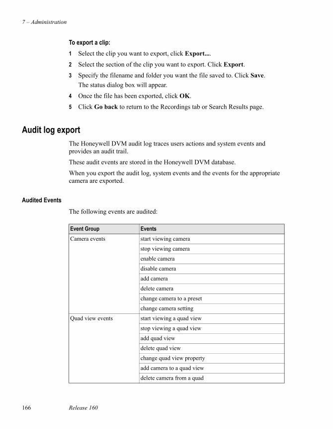
7 – Administration
166 Release 160
To export a clip:1 Select the clip you want to export, click Export....
2 Select the section of the clip you want to export. Click Export.
3 Specify the filename and folder you want the file saved to. Click Save.The status dialog box will appear.
4 Once the file has been exported, click OK.
5 Click Go back to return to the Recordings tab or Search Results page.
Audit log exportThe Honeywell DVM audit log traces users actions and system events and provides an audit trail.
These audit events are stored in the Honeywell DVM database.
When you export the audit log, system events and the events for the appropriate camera are exported.
Audited EventsThe following events are audited:
Event Group EventsCamera events start viewing camera
stop viewing camera
enable camera
disable camera
add camera
delete camera
change camera to a preset
change camera setting
Quad view events start viewing a quad view
stop viewing a quad view
add quad view
delete quad view
change quad view property
add camera to a quad view
delete camera from a quad
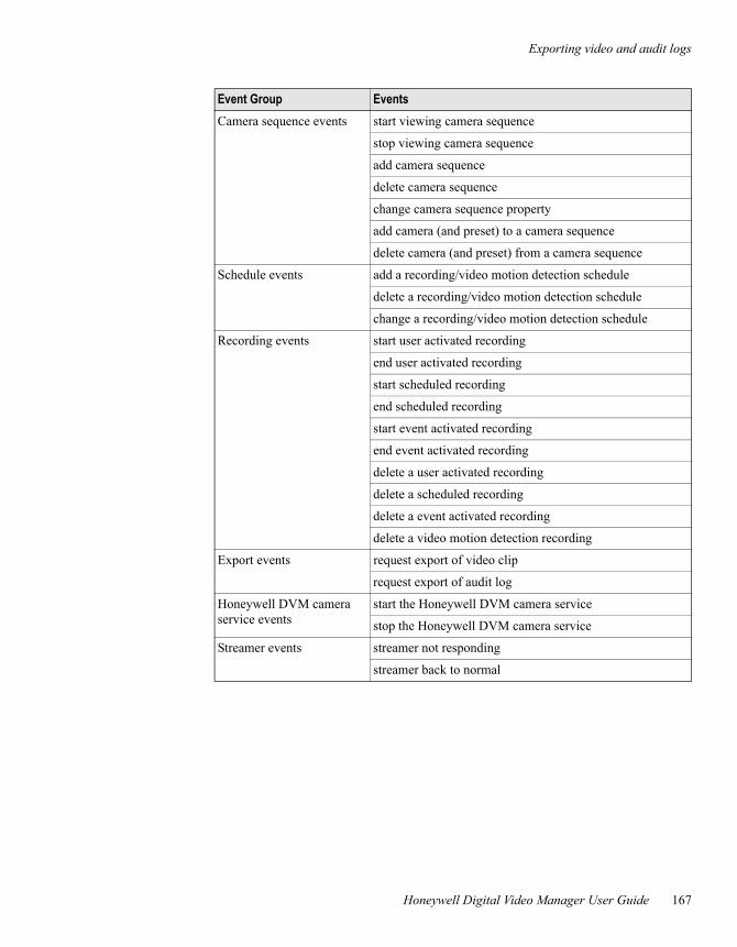
Exporting video and audit logs
Honeywell Digital Video Manager User Guide 167
Camera sequence events start viewing camera sequence
stop viewing camera sequence
add camera sequence
delete camera sequence
change camera sequence property
add camera (and preset) to a camera sequence
delete camera (and preset) from a camera sequence
Schedule events add a recording/video motion detection schedule
delete a recording/video motion detection schedule
change a recording/video motion detection schedule
Recording events start user activated recording
end user activated recording
start scheduled recording
end scheduled recording
start event activated recording
end event activated recording
delete a user activated recording
delete a scheduled recording
delete a event activated recording
delete a video motion detection recording
Export events request export of video clip
request export of audit log
Honeywell DVM camera service events
start the Honeywell DVM camera service
stop the Honeywell DVM camera service
Streamer events streamer not responding
streamer back to normal
Event Group Events
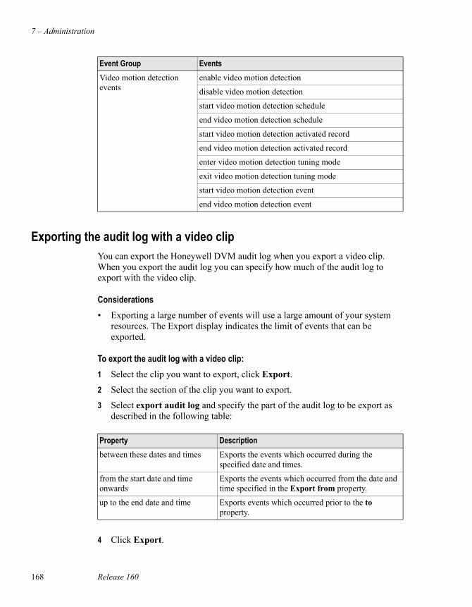
7 – Administration
168 Release 160
Exporting the audit log with a video clipYou can export the Honeywell DVM audit log when you export a video clip. When you export the audit log you can specify how much of the audit log to export with the video clip.
Considerations• Exporting a large number of events will use a large amount of your system
resources. The Export display indicates the limit of events that can be exported.
To export the audit log with a video clip:1 Select the clip you want to export, click Export.
2 Select the section of the clip you want to export.
3 Select export audit log and specify the part of the audit log to be export as described in the following table:
4 Click Export.
Video motion detection events
enable video motion detection
disable video motion detection
start video motion detection schedule
end video motion detection schedule
start video motion detection activated record
end video motion detection activated record
enter video motion detection tuning mode
exit video motion detection tuning mode
start video motion detection event
end video motion detection event
Event Group Events
Property Descriptionbetween these dates and times Exports the events which occurred during the
specified date and times.
from the start date and time onwards
Exports the events which occurred from the date and time specified in the Export from property.
up to the end date and time Exports events which occurred prior to the to property.
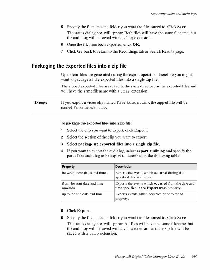
Exporting video and audit logs
Honeywell Digital Video Manager User Guide 169
5 Specify the filename and folder you want the files saved to. Click Save.The status dialog box will appear. Both files will have the same filename, but the audit log will be saved with a .log extension.
6 Once the files has been exported, click OK.
7 Click Go back to return to the Recordings tab or Search Results page.
Packaging the exported files into a zip fileUp to four files are generated during the export operation, therefore you might want to package all the exported files into a single zip file.
The zipped exported files are saved in the same directory as the exported files and will have the same filename with a .zip extension.
Example If you export a video clip named Frontdoor.wmv, the zipped file will be named Frontdoor.zip.
To package the exported files into a zip file:1 Select the clip you want to export, click Export.
2 Select the section of the clip you want to export.
3 Select package up exported files into a single zip file.
4 If you want to export the audit log, select export audit log and specify the part of the audit log to be export as described in the following table:
5 Click Export.
6 Specify the filename and folder you want the files saved to. Click Save.The status dialog box will appear. All files will have the same filename, but the audit log will be saved with a .log extension and the zip file will be saved with a .zip extension.
Property Descriptionbetween these dates and times Exports the events which occurred during the
specified date and times.
from the start date and time onwards
Exports the events which occurred from the date and time specified in the Export from property.
up to the end date and time Exports events which occurred prior to the to property.
7 – Administration
170 Release 160
7 Once the files has been exported, click OK.
8 Click Go back to return to the Recordings tab or Search Results page.
Verifying the exported Honeywell DVM filesExported Honeywell DVM files containing a digital signature can be verified by using the DVM Video Export Player application.
To verify an exported Honeywell DVM file:1 Select Start > Run, type HWDVSVerifyExports.exe and click OK.
The DVM Video Export Player will start.
2 Click Browse, select the video clip file and click Open.DVM Video Export Player will load the video and any attached audit log file and will attempt to verify the digital signature on the files.
Off-line storage and archiving
Honeywell Digital Video Manager User Guide 171
Off-line storage and archiving Off-line storage and archiving allows you to move clips to another physical storage device.
To store clips off-line, Honeywell DVM moves the data for selected clips to the archive folder (specified during the Honeywell DVM installation). You then back up the files using any backup program, for example NTBackup.
Any form of media can be used for off-line storage. (For example, tape or CD ROM.)
Prerequisites• You must be SUPV level or higher (to see the archive and restore buttons)
Archiving clips
To archive clips:1 Go to the Recordings tab.
2 Select the clips, on the clip selection grid. (You can select multiple clips for archiving.)
3 Click Archive.
Each clip has its own folder and uses the following naming convention:XXXX_mmddyyhhmmss_TTTTTTT_yyyy
Where:XXXX is the camera number.mmddyyhhmmss is the date and time the recording was activated by an event or a person.TTTTTTT is the type of recording. The types are user, schedule, event or motion.yyyy is the duration in seconds.
Once the clips have been moved, the clip data is no longer available from the short or medium term storage and marked as off-line in the Honeywell DVM database. The text will also be grayed in the clip grid.
7 – Administration
172 Release 160
Restoring clips
Prerequisites• The files you want to restore must be in the Honeywell DVM file system.
Use the Restore to original location option in your backup package to copy the files from the off-line storage media to the original folder.
To restore clips:1 Go to the Recordings tab.
2 Select the off-line clip in the clip grid. (You can only restore one clip at a time.)
3 Click Restore. If all the files for that clip are available the clip will be restored.
The clip is now marked in the Honeywell DVM database as restored and is displayed in blue in the clip grid. The status is the same as the original clip type.
Next time the restored clip is selected for archiving, a second copy will not be made on tape. The data is deleted from short or medium term storage and the clip is marked as off-line in the clip grid.
If an archived clip is selected for deleting, the record in the database and all files that exist on the Honeywell DVM system for that clip (restored or in the archive buffer on disk) are deleted.
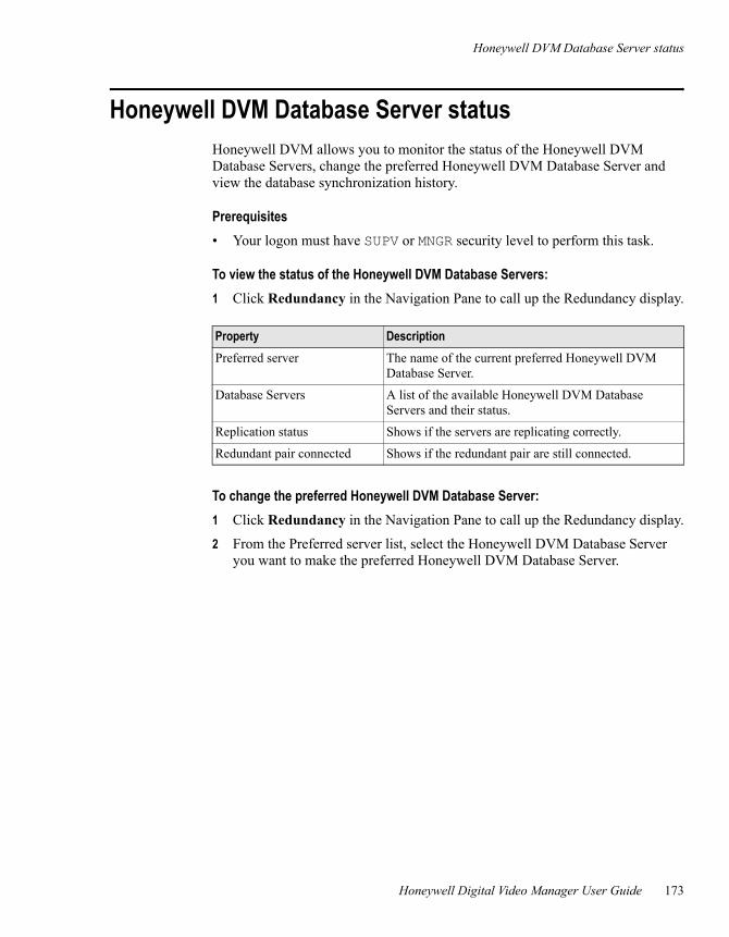
Honeywell DVM Database Server status
Honeywell Digital Video Manager User Guide 173
Honeywell DVM Database Server statusHoneywell DVM allows you to monitor the status of the Honeywell DVM Database Servers, change the preferred Honeywell DVM Database Server and view the database synchronization history.
Prerequisites• Your logon must have SUPV or MNGR security level to perform this task.
To view the status of the Honeywell DVM Database Servers:1 Click Redundancy in the Navigation Pane to call up the Redundancy display.
To change the preferred Honeywell DVM Database Server:1 Click Redundancy in the Navigation Pane to call up the Redundancy display.
2 From the Preferred server list, select the Honeywell DVM Database Server you want to make the preferred Honeywell DVM Database Server.
Property DescriptionPreferred server The name of the current preferred Honeywell DVM
Database Server.
Database Servers A list of the available Honeywell DVM Database Servers and their status.
Replication status Shows if the servers are replicating correctly.
Redundant pair connected Shows if the redundant pair are still connected.
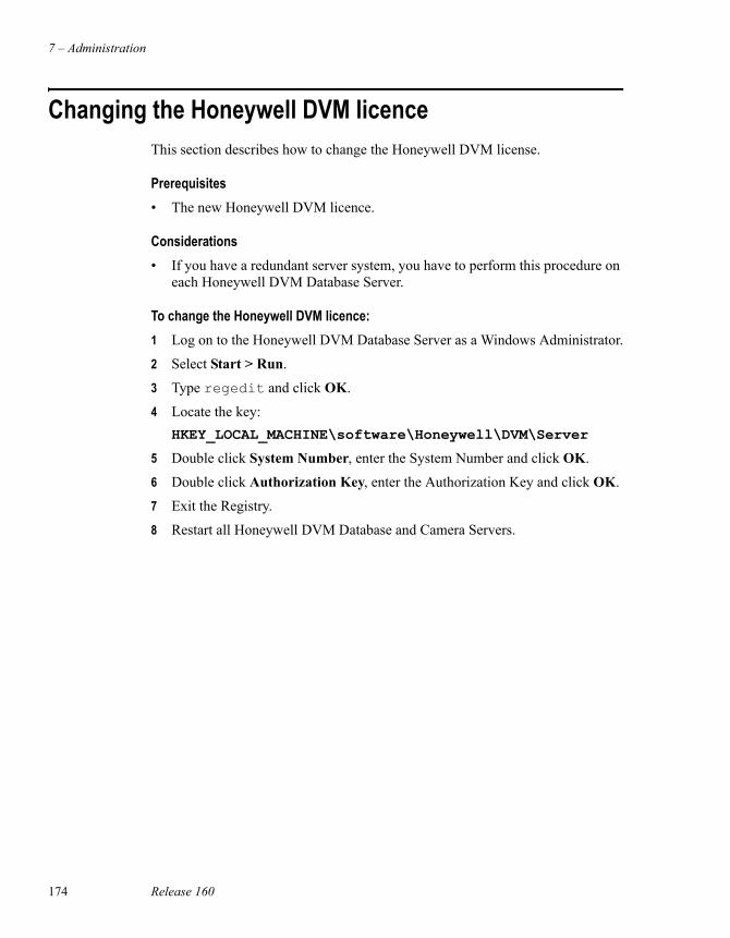
7 – Administration
174 Release 160
Changing the Honeywell DVM licenceThis section describes how to change the Honeywell DVM license.
Prerequisites• The new Honeywell DVM licence.
Considerations• If you have a redundant server system, you have to perform this procedure on
each Honeywell DVM Database Server.
To change the Honeywell DVM licence:1 Log on to the Honeywell DVM Database Server as a Windows Administrator.
2 Select Start > Run.
3 Type regedit and click OK.
4 Locate the key:HKEY_LOCAL_MACHINE\software\Honeywell\DVM\Server
5 Double click System Number, enter the System Number and click OK.
6 Double click Authorization Key, enter the Authorization Key and click OK.
7 Exit the Registry.
8 Restart all Honeywell DVM Database and Camera Servers.
Honeywell Digital Video Manager User Guide 175
8Troubleshooting
This chapter describes how to use the Performance Monitor and open the log file. It also describes how to overcome common problems.
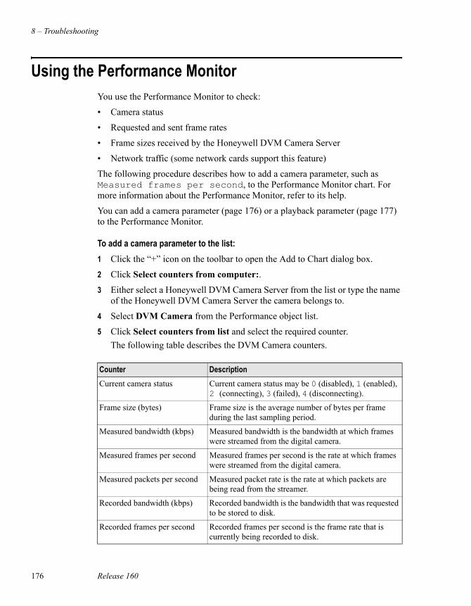
8 – Troubleshooting
176 Release 160
Using the Performance MonitorYou use the Performance Monitor to check:
• Camera status
• Requested and sent frame rates
• Frame sizes received by the Honeywell DVM Camera Server
• Network traffic (some network cards support this feature)
The following procedure describes how to add a camera parameter, such as Measured frames per second, to the Performance Monitor chart. For more information about the Performance Monitor, refer to its help.
You can add a camera parameter (page 176) or a playback parameter (page 177) to the Performance Monitor.
To add a camera parameter to the list:1 Click the “+” icon on the toolbar to open the Add to Chart dialog box.
2 Click Select counters from computer:.
3 Either select a Honeywell DVM Camera Server from the list or type the name of the Honeywell DVM Camera Server the camera belongs to.
4 Select DVM Camera from the Performance object list.
5 Click Select counters from list and select the required counter.The following table describes the DVM Camera counters.
Counter DescriptionCurrent camera status Current camera status may be 0 (disabled), 1 (enabled),
2 (connecting), 3 (failed), 4 (disconnecting).
Frame size (bytes) Frame size is the average number of bytes per frame during the last sampling period.
Measured bandwidth (kbps) Measured bandwidth is the bandwidth at which frames were streamed from the digital camera.
Measured frames per second Measured frames per second is the rate at which frames were streamed from the digital camera.
Measured packets per second Measured packet rate is the rate at which packets are being read from the streamer.
Recorded bandwidth (kbps) Recorded bandwidth is the bandwidth that was requested to be stored to disk.
Recorded frames per second Recorded frames per second is the frame rate that is currently being recorded to disk.
Using the Performance Monitor
Honeywell Digital Video Manager User Guide 177
6 Click Select instances from list and select the instance.
7 Click Add, then click Close.
8 Right-click on the counter and select Properties to open the System Monitor Properties dialog box.
9 Change the properties as required, click Apply, then click OK.
The camera parameter appears in the chart.
To add a playback parameter to the list:1 Click the “+” icon on the toolbar to open the Add to Chart dialog box.
2 Click Select counters from computer:.
3 Either select a Honeywell DVM Camera Server from the list or type the name of the Honeywell DVM Camera Server the camera belongs to.
4 Select DVM Playback from the Performance object list.
5 Click Select counters from list and select the required counter.The following table describes the DVM Camera counters.
6 Click Select instances from list and select the instance.
7 Click Add, then click Close.
Recorded packets per second Recorded packets per second is the packet rate that is currently being recorded to disk.
Requested bandwidth (kbps) Requested bandwidth is the bandwidth that was requested of the digital camera.
Requested frames per second Requested frames per second is the frame rate that was requested of the digital camera.
Counter Description
Counter DescriptionCurrent playback speed Current playback speed is the ratio of playback
frame rate to the recorded frame rate.
Current playback status Current playback status may be 0 (paused), 1 (forward play), 2 (reverse play).
Measured frames per second Measured frames per second is the rate at which frames were streamed from the Honeywell DVM Camera Server.
Measured playback packets per Second
Measured packet rate is the rate at which packets were streamed from the Honeywell DVM Camera Server as specified on the Camera Definition tab.
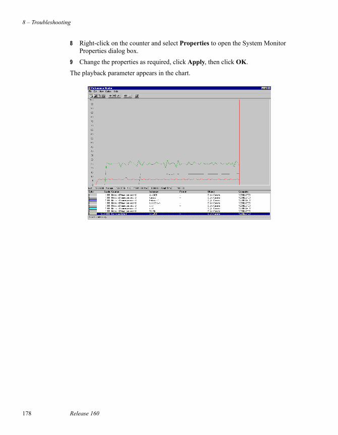
8 – Troubleshooting
178 Release 160
8 Right-click on the counter and select Properties to open the System Monitor Properties dialog box.
9 Change the properties as required, click Apply, then click OK.
The playback parameter appears in the chart.
Configuring the Engineering Log
Honeywell Digital Video Manager User Guide 179
Configuring the Engineering LogConsiderations• Where you would normally enter \ in a folder path, you will need to
enter \\. For example, where you would normally enter c:\, you will need to enter c:\\.
Honeywell DVM maintains an engineering log to record events and error messages which can assist with troubleshooting and problem resolution. The default filename is DVM.log and is normally found in the following folders:
• On the Honeywell DVM Database and Camera Servers, in \honeywell\digitalvideomanager\server\logs
• On a client computer, in \honeywell\digitalvideomanager\client\logs
The settings for the engineering log are configured using hwdvslogconfig.exe which is found:
• On the server in \DigitalVideoManager\Bin
• On the client in \DigitalVideoClient
It contains two sections, Log Settings and Paranoid Levels.
The Log Settings define the folder the engineering log will be saved to, the maximum size of the file, the file name and once the log file reaches it’s maximum size, what the old file will be renamed to.
Each of the Paranoid Levels relate to a subsystem of Honeywell DVM and determine what will be included in the engineering log. The values range from 0 to 100, the higher the value, the more information is captured in the log. The default is 10.
NoteThe engineering log is different to the audit log. The engineering log contains diagnostic information which will assist with troubleshooting Honeywell DVM issues. The audit log is a log of user and system actions for use as an audit trail.
8 – Troubleshooting
180 Release 160
To modify the engineering log settings:1 Click Modify to make the fields editable.
2 Change the values.
3 Click Save. If you made changes which require the DVM Logger Service to be restarted you will receive a message informing you of this. Click OK and restart the DVM Logger Service.
To restart the DVM Logger Service:1 From the Start menu, select Settings > Control Panel > Administrative
Tools to open the Administrative Tools dialog box.
2 Double-click Services.
3 Right-click DVM Logger and select Stop.A message appears informing you which other services will also be stopped when the DVM Logger is stopped.Click Yes to stop all the listed services.
4 Right-click DVM Logger and select Start.
5 Restart all other services which were stopped when the DVM Logger service was stopped.
6 Close the Services dialog box and then close the Administrative Tools dialog box.
Common problems
Honeywell Digital Video Manager User Guide 181
Common problems
Honeywell DVM displaysIf the text labels do not appear on the Honeywell DVM displays, restart the Web Site. To do this:
1 On the server, select Start > Control Panel > Administrative Tools > Internet Service Manager.
2 Right-click on the computer name and select Restart IIS.
3 Click OK when the dialog is displayed and wait for IIS to be restarted.
4 Once IIS has restarted, go to the client and start Internet Explorer.
5 From the Tools menu select Internet Options.
6 Click the Delete Files button on the General Tab.
7 When the Delete Files dialog box appears, click OK then click OK again to close the Internet Options dialog box.
Event ActivationIf you are having problems with Event Activation, check the following:
1 Check if evtact is running on the EBI, PlantScape, or Experion PKS server. To do this:On the EBI, PlantScape, or Experion PKS server, open a Command Prompt window and enter the command:Usrlrn -a -pThis lists all the tasks that are running on the EBI server. If it does not show evtact, at the command prompt enter:addtsk evtact <LRN>where <LRN> is the LRN of the evtact task. (For more information, see “Configuring event-activated recording” on page 126.)
2 Make sure the point has been configured correctly. (For more information, see “Configuring event-activated recording” on page 126.)
3 Check that the Windows mngr account exists on the Honeywell DVM server and that its password is the same as the EBI, PlantScape, or Experion PKS servers mngr account.
8 – Troubleshooting
182 Release 160
Video streaming qualityIf the video is not streaming smoothly, check the network cards are set to full duplex and you have the latest network drivers installed.
Video not streamingIf the video is not streaming or you are having problems with the camera status try the following:
1 If you have multiple network cards, that is one for streaming in and one for streaming out, check if the client subnet adapter address is configured correctly.To do this, check the ClientSubnetAdapterAddress box in tblCameraManager in the Honeywell DVM database. This field should contain the IP address of the network card connected to the client subnet.
2 Ping the camera. If you receive time-outs then the network may not be properly configured.
3 Navigate to the streamer web pages. Check whether video can be streamed directly from the streamer web pages.
Camera will not recordIf the camera will not record, check the following:
1 Check the area of the hard drive that you are recording to is NTFS.
2 Make sure that there is sufficient disk space on the server.
Access deniedYou do not have permission to access DVM.
If you received this message when you attempted to access the Honeywell DVM web site, check the following:
1 Check all Windows accounts and passwords have been configured correctly. For more information about security, see “Security” on page 158.
2 If account names and passwords were changed, reboot the computers it was done on.
3 Make sure the Honeywell DVM client was installed after Station was installed.
Common problems
Honeywell Digital Video Manager User Guide 183
Station errorsUnable to contact DVM server. The server may be down.
orError initializing DVM
If you receive either or these errors in Station, check the following:
1 Check the access privileges. Make sure windows accounts and passwords have been set up correctly.
2 Close and restart Station.
InternationalizationIf your text is appearing in English instead of the specified language, check the following:
1 The version of Honeywell DVM installed on your system is an internationalized version.
2 The appropriate language pack has been installed on the Honeywell DVM server and client computers.
3 Restart the web server. See “Honeywell DVM displays” on page 181, for the procedures for restarting a web server.
Recording icon does not appear on a live viewIf the recording icon does not appear on a live view, check you have specified record for on the Recordings tab.
Recording details appear in blue or grey textDetails of a recording appearing in grey text are recordings that are archived.
Details of a recording appearing in blue text are recordings that have been restored from an archive.
Live video mouse PTZ controls do not appearCheck whether the camera supports continuous PTZ.
Video does not appear in quad viewIf the video does not appear, check the camera is in an area that the operator is allowed to view.
8 – Troubleshooting
184 Release 160
Pages available in Internet Explorer do not match the security levelIf the pages available are not what should be available for that security level, refresh your page.
Unable to view live videoThe camera is unavailable due to problems with the camera’s server
If you received this message when you attempted to view live video, you must add the IP address and name of all Honeywell DVM Database and Camera Servers to the following hosts files:
• Honeywell DVM Camera Servers
• EBI, PlantScape, or Experion PKS servers
• Stations
• Internet Explorer client
To add the IP address to the hosts file:1 Select Start > Programs > Accessories > Command Prompt to open a
Command Prompt window.
2 At the c:\> prompt, change to the folder for the hosts file:cd winnt\system32\drivers\etc
3 Open the hosts file by typing: notepad hosts
4 Move to the last line and type:a.b.c.d video_server_namewhere, a.b.c.d is the IP address and video_server_name is the Host Name of the Honeywell DVM Database or Camera Server.For example, the new line may look like this:200.0.0.84 DVM_Server2
After editing the hosts file, you should confirm that the computer can resolve the name that you have added.
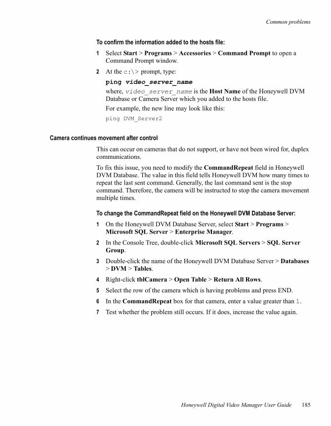
Common problems
Honeywell Digital Video Manager User Guide 185
To confirm the information added to the hosts file:1 Select Start > Programs > Accessories > Command Prompt to open a
Command Prompt window.
2 At the c:\> prompt, type:ping video_server_name where, video_server_name is the Host Name of the Honeywell DVM Database or Camera Server which you added to the hosts file.For example, the new line may look like this:ping DVM_Server2
Camera continues movement after controlThis can occur on cameras that do not support, or have not been wired for, duplex communications.
To fix this issue, you need to modify the CommandRepeat field in Honeywell DVM Database. The value in this field tells Honeywell DVM how many times to repeat the last sent command. Generally, the last command sent is the stop command. Therefore, the camera will be instructed to stop the camera movement multiple times.
To change the CommandRepeat field on the Honeywell DVM Database Server:1 On the Honeywell DVM Database Server, select Start > Programs >
Microsoft SQL Server > Enterprise Manager.
2 In the Console Tree, double-click Microsoft SQL Servers > SQL Server Group.
3 Double-click the name of the Honeywell DVM Database Server > Databases > DVM > Tables.
4 Right-click tblCamera > Open Table > Return All Rows.
5 Select the row of the camera which is having problems and press END.
6 In the CommandRepeat box for that camera, enter a value greater than 1.
7 Test whether the problem still occurs. If it does, increase the value again.

8 – Troubleshooting
186 Release 160
Honeywell Digital Video Manager User Guide 1
Index
Aaccess points, configuring event-activated
recording 126accounts
Windows 29administration 157architecture, system 4Axis 2100, installing and configuring 74Axis 2120, installing and configuring 74Axis 2400, installing and configuring 75Axis 2401, installing and configuring 75Axis 2420, installing and configuring 74
Bbandwidth, network
estimating requirements 13typical image requirements 14typical network 23
CCamera Servers
described 4, 36installing Honeywell DVM components 65requirements for 36
camera streamersdescribed 4installing and configuring 73
camerasadding 90configuration tabs
Camera Control 95Camera Definition 90Recording Presets 94
configuring 90controls 142
disabling and enabling 144requirements 42streamers 43types of 42viewing its video 140
compression level 13configuration tasks 89
DDatabase Servers
described 4, 36installing Honeywell DVM components 57requirements for 36
design issues 9digital certificate
configuring 136installing a third party certificate 137
disabling a camera 144displays
creating custom 117viewing live video 140
EEBI
described 6integration 6, 28server
described 4installing Honeywell DVM
components 67enabling a camera 144error log 179event-activated recording, configuring 126Experion PKS
described 6integration 6
2 Release 160
Index
Fframe rate 13
Hhardware and software requirements 44
IIC109A cabling 81image complexity 13image size 13image type (color or black and white) 13installation tasks 47integration with EBI 6integration with Experion PKS 6
Kkeypad, using the numeric 155
Llog, error 179
MMD-100, installing and configuring 82Megachips MD-100, installing and
configuring 82multicasting 26
Nnetwork
architectureconventional 11dedicated 12types of 11VLAN 12
bandwidths, typical 23design
issues 10tips 25
management 27
numeric keypad, using 155
OOpennetView, installing and configuring 79operation 139operator IDs, Station 29overview 3
PPelco PTZ cameras
installingAxis 2401 55
performance monitor 176planning issues 9presets
predefined camera positions 143recordings 94
Qquad view
creating 103described 89viewing 146
Rrecorded videos
presets 94scheduling 100searching 150viewing 148
recording controls 142redundant servers
synchronizingdate and time 59
Index
Honeywell Digital Video Manager User Guide 3
Sschedule, creating 100searching recorded videos 150, 154security 30security levels 29Sensomatic cameras
installing 55sequence
creating 104viewing 147
serverCamera 36Database 36
snapshot control 142snapshot, configuring 105software and hardware requirements 44Station
operator IDs 29Stations
described 6installing Honeywell DVM components 69requirements 29
status points, configuring event-activated recording 127
storage requirementscalculating 23factors effecting 13typical 14
streamers, camera 43synchronizing
date and time 59
TTime Service application 59transmission techniques 26troubleshooting 175
Uunicasting 26
Vvideo requirements 42videos
searching recorded 150viewing live 140viewing recorded 148
viewinglive video 140recorded videos 148
VLAN, described 12


