The following table specifies the recommended resistance range for each power
supply voltage (Non-Intrinsically Safe).
NOTE: The resistance value is the total sum of the series resistor (or PLC
resistance) and the lines resistance. The minimum voltage level on terminals
should not be less that 15 VDC.
To maintain a proper seal, make sure that conduit is firmly screwed to the conduit's
adaptor.
Ripple/Noise Parameters Recommended for the Power Supply
The following ripple/noise parameter are recommended for the power supply:
• 100 mV p-p max.
Power Supply Types Recommendations
• Prefer a regulated switching power supply.
• A rectified power supply is not recommended.
• When powering by a battery, avoid the using of switched charger.
Feeding Via PLC
• Verify that the voltage level on the unit’s terminals is at least 15 VDC.
• Check PLC specifications for grounding options.
• It is good practice to add a 150 Ω series resistor between the unit's positive
terminal and the PLC.
Pipe Length
1.64 ft (0.5 m)
Internal Pipe Diameter
≥ 3.0˝ (76.2 mm)
Power Supply
Voltage
15 V
18 V
24 V
28 V
Minimum
Resistance Value
0 Ω
0 Ω
41 Ω
68 Ω
Maximum
Resistance Value
136 Ω
272 Ω
545 Ω
727 Ω
Page 4
a b
L-UL:SSS-1000 12/15/10 8:56 AM Page 5
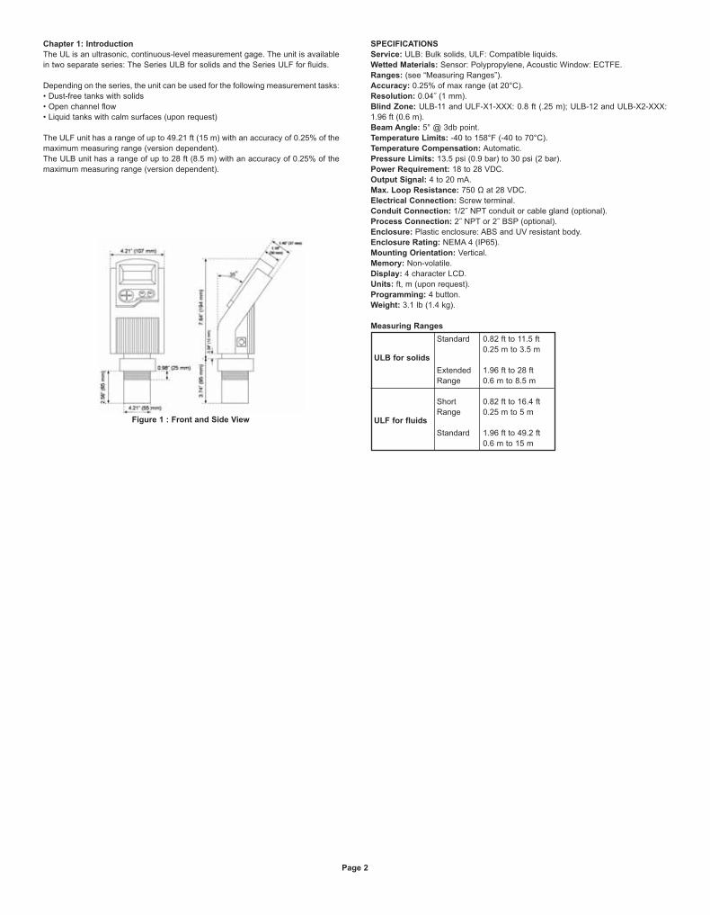
Chapter 3: Setting Up and Calibrating the Unit
This chapter explains how to set up and calibrate the unit for accurate
measurement monitoring.
The unit is supplied with preprogrammed default settings, making it ready for
immediate operation. There is no need to change the default settings, unless you
wish to calibrate the unit for your specific requirements; however, it is
recommended that you replace the default tank height value with the actual tank
height, as described on page 6. When using the unit, the tank height is calculated
as the distance from the surface of the sensor to the bottom of the tank. You should
enter this value whenever tank height is required. (For flow measurement, enter the
precise flume height.)
The ULF unit contains eleven programs and the ULB unit contains nine programs.
These programs are referred to as functions, which enable you to change the
default settings and calibrate as required. These functions are accessed from a
functions menu. The functions Pr01, Pr02, Pr04 and Pr05 are the most important
to ensure correct usage of your device (with the addition of Pr00 if using the
appropriate ULF series). Function Pr03 may be used if there are interfering signals.
The remaining functions (Pr06, Pr07, Pr08, Pr09 and Pr10) enable you to
customize the unit for your monitoring requirements or to restore factory default
settings.
The diagram below shows the functions available in the functions menus for the
Series ULF and Series ULB. Some functions are only relevant for particular series.
Figure 7: Function Menus
Setting flow measurement parameters (function Pr00) for the Series ULF (Open
Channels) is described in Chapter 4, Open Channels (ULF). Setting parameters
for all other functions and accessing the functions are described in this chapter.
Using Series UL Functions
The LCD display screen, functioning in "normal" mode, provides continuously
updated measurement readings. The display screen is also used to view the
menu options, function settings and data values, accessed by using the function
buttons.
The picture below shows the upper part of the unit.
Figure 8: Display and Function Buttons
The function buttons are used to perform various operations, summarized in the
following table.
NOTE: Within some functions, the digits in the displayed value can be individually
modified. This is indicated by a flashing digit (flashing digits are shown in gray in
the display illustrations. In this case, the ENT and ESC buttons enable you to move
between the digits. Each flashing digit can be modified using the BACK and NEXT
buttons.
Start Up and Function Access:
Button Uses Include:
• Accessing the functions menu (when pressed
simultaneously with )
• Selecting functions
• Progressing to the next step of a function
• Moving from left to right between displayed digits
• Saving changes to data
• Accessing the functions menu (when pressed
simultaneously with )
• Exiting the functions menu to restore the
distance reading
• Moving from right to left between displayed digits
• Exiting a function without saving changes
• Clearing error messages
• Scrolling through the functions menu
• Scrolling through available data values in
functions
• NEXT button only: Recording interfering signals
Press/Action
Connect unit to
power supply
After a brief pause
Display:
For example:
For example:
Explanation
Temporary display while
unit takes a reading.
Distance reading.
Enters the functions
menu.
Used to search for the
required menu selection.
Accesses the selected
function.
or
and(simultaneously)
Page 5
or
L-UL:SSS-1000 12/15/10 8:58 AM Page 6
NOTE: If an error message appears, press the ESC button to return to the
main menu.
Values are displayed in feet and inches or meters and centimeters (model
dependent).
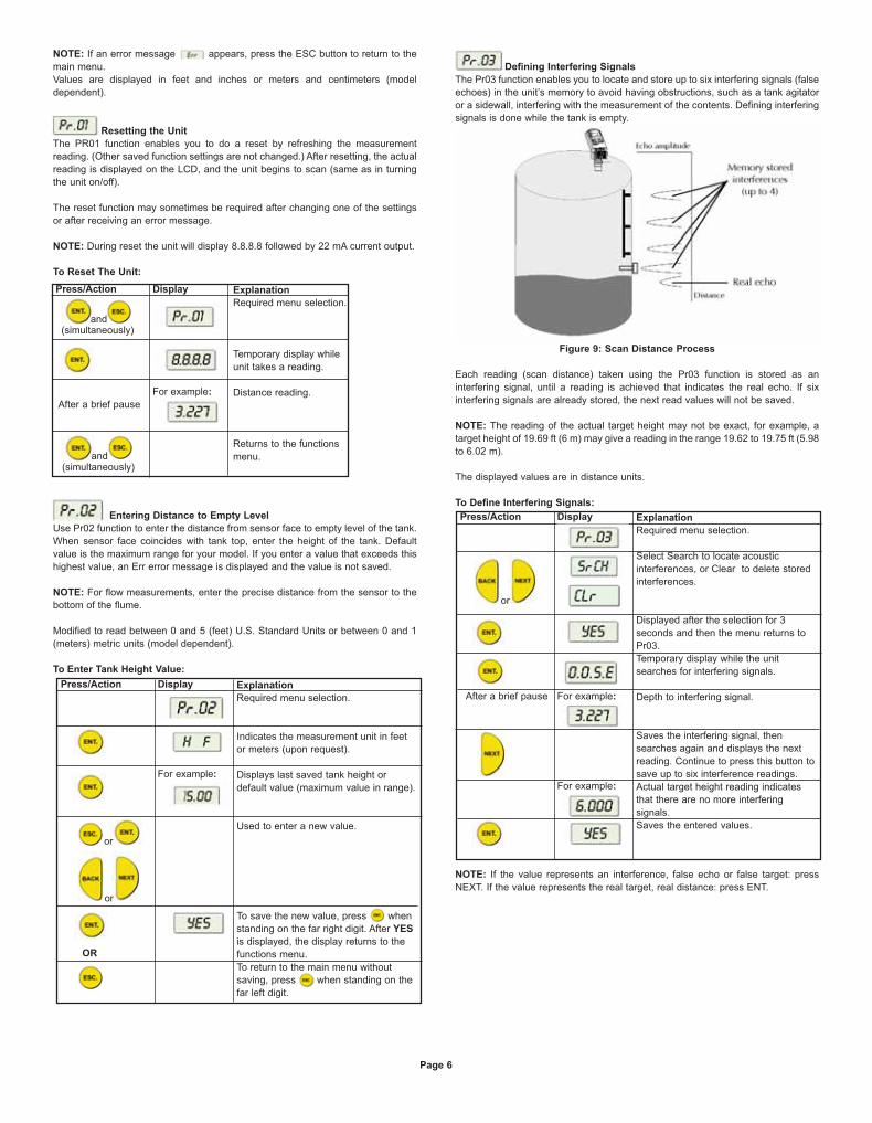
Resetting the Unit
The PR01 function enables you to do a reset by refreshing the measurement
reading. (Other saved function settings are not changed.) After resetting, the actual
reading is displayed on the LCD, and the unit begins to scan (same as in turning
the unit on/off).
The reset function may sometimes be required after changing one of the settings
or after receiving an error message.
NOTE: During reset the unit will display 8.8.8.8 followed by 22 mA current output.
To Reset The Unit:
Entering Distance to Empty Level
Use Pr02 function to enter the distance from sensor face to empty level of the tank.
When sensor face coincides with tank top, enter the height of the tank. Default
value is the maximum range for your model. If you enter a value that exceeds this
highest value, an Err error message is displayed and the value is not saved.
NOTE: For flow measurements, enter the precise distance from the sensor to the
bottom of the flume.
Modified to read between 0 and 5 (feet) U.S. Standard Units or between 0 and 1
(meters) metric units (model dependent).
To Enter Tank Height Value:
Defining Interfering Signals
The Pr03 function enables you to locate and store up to six interfering signals (false
echoes) in the unit’s memory to avoid having obstructions, such as a tank agitator
or a sidewall, interfering with the measurement of the contents. Defining interfering
signals is done while the tank is empty.
Figure 9: Scan Distance Process
Each reading (scan distance) taken using the Pr03 function is stored as an
interfering signal, until a reading is achieved that indicates the real echo. If six
interfering signals are already stored, the next read values will not be saved.
NOTE: The reading of the actual target height may not be exact, for example, a
target height of 19.69 ft (6 m) may give a reading in the range 19.62 to 19.75 ft (5.98
to 6.02 m).
The displayed values are in distance units.
To Define Interfering Signals:
NOTE: If the value represents an interference, false echo or false target: press
NEXT. If the value represents the real target, real distance: press ENT.
Press/Action
After a brief pause
Display
For example:
Explanation
Required menu selection.
Temporary display while
unit takes a reading.
Distance reading.
Returns to the functions
menu.
and(simultaneously)
and(simultaneously)
Press/Action Display
For example:
Explanation
Required menu selection.
Indicates the measurement unit in feet
or meters (upon request).
Displays last saved tank height or
default value (maximum value in range).
Used to enter a new value.
To save the new value, press when
standing on the far right digit. After YES
is displayed, the display returns to the
functions menu.
To return to the main menu without
saving, press when standing on the
far left digit.
or
or
OR
Press/Action
After a brief pause
Display
For example:
For example:
Explanation
Required menu selection.
Select Search to locate acoustic
interferences, or Clear to delete stored
interferences.
Displayed after the selection for 3
seconds and then the menu returns to
Pr03.
Temporary display while the unit
searches for interfering signals.
Depth to interfering signal.
Saves the interfering signal, then
searches again and displays the next
reading. Continue to press this button to
save up to six interference readings.
Actual target height reading indicates
that there are no more interfering
signals.
Saves the entered values.
or
Page 6
L-UL:SSS-1000 12/15/10 9:01 AM Page 7
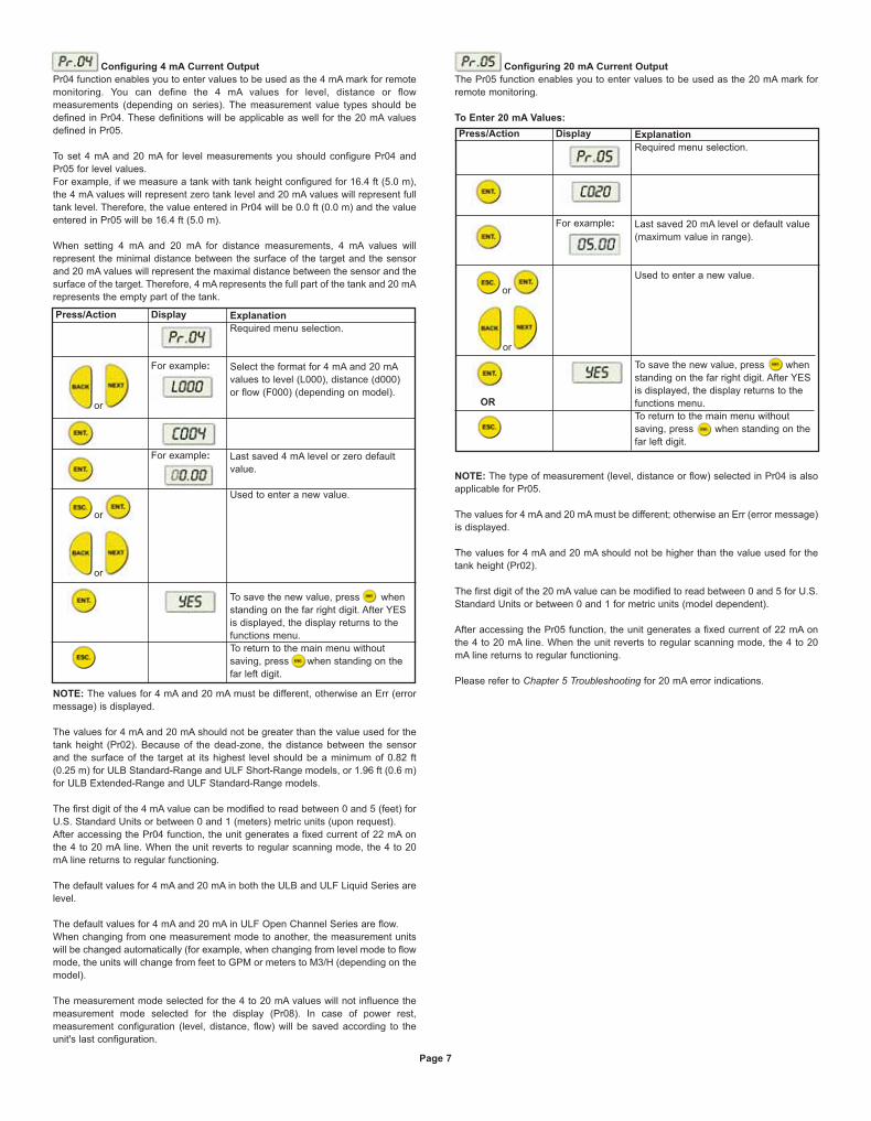
Configuring 4 mA Current Output
Pr04 function enables you to enter values to be used as the 4 mA mark for remote
monitoring. You can define the 4 mA values for level, distance or flow
measurements (depending on series). The measurement value types should be
defined in Pr04. These definitions will be applicable as well for the 20 mA values
defined in Pr05.
To set 4 mA and 20 mA for level measurements you should configure Pr04 and
Pr05 for level values.
For example, if we measure a tank with tank height configured for 16.4 ft (5.0 m),
the 4 mA values will represent zero tank level and 20 mA values will represent full
tank level. Therefore, the value entered in Pr04 will be 0.0 ft (0.0 m) and the value
entered in Pr05 will be 16.4 ft (5.0 m).
When setting 4 mA and 20 mA for distance measurements, 4 mA values will
represent the minimal distance between the surface of the target and the sensor
and 20 mA values will represent the maximal distance between the sensor and the
surface of the target. Therefore, 4 mA represents the full part of the tank and 20 mA
represents the empty part of the tank.
NOTE: The values for 4 mA and 20 mA must be different, otherwise an Err (error
message) is displayed.
The values for 4 mA and 20 mA should not be greater than the value used for the
tank height (Pr02). Because of the dead-zone, the distance between the sensor
and the surface of the target at its highest level should be a minimum of 0.82 ft
(0.25 m) for ULB Standard-Range and ULF Short-Range models, or 1.96 ft (0.6 m)
for ULB Extended-Range and ULF Standard-Range models.
The first digit of the 4 mA value can be modified to read between 0 and 5 (feet) for
U.S. Standard Units or between 0 and 1 (meters) metric units (upon request).
After accessing the Pr04 function, the unit generates a fixed current of 22 mA on
the 4 to 20 mA line. When the unit reverts to regular scanning mode, the 4 to 20
mA line returns to regular functioning.
The default values for 4 mA and 20 mA in both the ULB and ULF Liquid Series are
level.
The default values for 4 mA and 20 mA in ULF Open Channel Series are flow.
When changing from one measurement mode to another, the measurement units
will be changed automatically (for example, when changing from level mode to flow
mode, the units will change from feet to GPM or meters to M3/H (depending on the
model).
The measurement mode selected for the 4 to 20 mA values will not influence the
measurement mode selected for the display (Pr08). In case of power rest,
measurement configuration (level, distance, flow) will be saved according to the
unit's last configuration.
Configuring 20 mA Current Output
The Pr05 function enables you to enter values to be used as the 20 mA mark for
remote monitoring.
To Enter 20 mA Values:
NOTE: The type of measurement (level, distance or flow) selected in Pr04 is also
applicable for Pr05.
The values for 4 mA and 20 mA must be different; otherwise an Err (error message)
is displayed.
The values for 4 mA and 20 mA should not be higher than the value used for the
tank height (Pr02).
The first digit of the 20 mA value can be modified to read between 0 and 5 for U.S.
Standard Units or between 0 and 1 for metric units (model dependent).
After accessing the Pr05 function, the unit generates a fixed current of 22 mA on
the 4 to 20 mA line. When the unit reverts to regular scanning mode, the 4 to 20
mA line returns to regular functioning.
Please refer to Chapter 5 Troubleshooting for 20 mA error indications.
Press/Action Display
For example:
For example:
Explanation
Required menu selection.
Select the format for 4 mA and 20 mA
values to level (L000), distance (d000)
or flow (F000) (depending on model).
Last saved 4 mA level or zero default
value.
Used to enter a new value.
To save the new value, press when
standing on the far right digit. After YES
is displayed, the display returns to the
functions menu.
To return to the main menu without
saving, press when standing on the
far left digit.
or
or
or
Press/Action Display
For example:
Explanation
Required menu selection.
Last saved 20 mA level or default value
(maximum value in range).
Used to enter a new value.
To save the new value, press when
standing on the far right digit. After YES
is displayed, the display returns to the
functions menu.
To return to the main menu without
saving, press when standing on the
far left digit.
or
or
OR
Page 7
L-UL:SSS-1000 12/15/10 9:03 AM Page 8
Selecting Low/High Dynamic Speed (ULF Series Only)
The Pr06 function enables you to choose the required speed level. There are two
settings available:
• SE 0: Low dynamic mode (default setting). This mode provides slower readings
with a greater degree of accuracy (rate of up to 31˝/80 cm per min).
• Fail Safe: 10 minutes.
• SE 1: High dynamic mode. This mode provides faster readings but with less
precision (rate of up to 39˝/100 cm per min).
• Fail Safe: 3 minutes.
NOTE: Fail Safe timer determines the waiting period from an echo loss until a
transmission of an error signal.
To Select the Speed Mode:
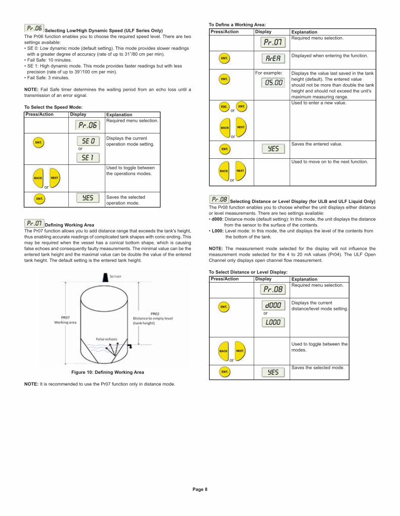
Defining Working Area
The Pr07 function allows you to add distance range that exceeds the tank's height,
thus enabling accurate readings of complicated tank shapes with conic ending. This
may be required when the vessel has a conical bottom shape, which is causing
false echoes and consequently faulty measurements. The minimal value can be the
entered tank height and the maximal value can be double the value of the entered
tank height. The default setting is the entered tank height.
Figure 10: Defining Working Area
NOTE: It is recommended to use the Pr07 function only in distance mode.
To Define a Working Area:
Selecting Distance or Level Display (for ULB and ULF Liquid Only)
The Pr08 function enables you to choose whether the unit displays either distance
or level measurements. There are two settings available:
• d000: Distance mode (default setting): In this mode, the unit displays the distance
from the sensor to the surface of the contents.
• L000: Level mode: In this mode, the unit displays the level of the contents from
the bottom of the tank.
NOTE: The measurement mode selected for the display will not influence the
measurement mode selected for the 4 to 20 mA values (Pr04). The ULF Open
Channel only displays open channel flow measurement.
To Select Distance or Level Display:
Press/Action Display Explanation
Required menu selection.
Displays the current
operation mode setting.
Used to toggle between
the operations modes.
Saves the selected
operation mode.
or
or
Press/Action Display
For example:
Explanation
Required menu selection.
Displayed when entering the function.
Displays the value last saved in the tank
height (default). The entered value
should not be more than double the tank
height and should not exceed the unit's
maximum measuring range.
Used to enter a new value.
Saves the entered value.
Used to move on to the next function.
or
or
or
Press/Action Display Explanation
Required menu selection.
Displays the current
distance/level mode setting.
Used to toggle between the
modes.
Saves the selected mode.
or
or
Page 8
L-UL:SSS-1000 12/15/10 9:06 AM Page 9
Entering Factor for Gas Compensation
Function Pr09 enables you to compensate for sound velocity changes in different
types of gasses. You can enter the appropriate factor for each type of gas listed on
the “Gas Factor Table” (Appendix A). For example, the sound velocity in air (at
room temperature) is 1125 ft/sec (343 m/sec) and for Methane (Ch4) 1463 ft/sec
(445.82 m/sec). Therefore, a factor of 1463/1125 = 1.30 should be entered to
compensate for this type of gas. This factor will compensate in cases when the gas
compound consists of 100% Methane. In case the gas is not pure, the sound
velocity cannot be estimated and therefore a minor deviation could appear. It is
recommended to use a reference measurement indicator (using a tape or other
measuring device) and compare the measurement results between the unit and the
reference measurement indicator. If the result is correct, press ENT. If the accuracy
deviation is higher than expected, continue and calibrate the factor to meet the gas
maintained in the vessel. For example, if the gas composition consists of water and
gas you can add ± 0.01 to the factor figure already entered, to meet your
application requirements.
The “Gas Factor Table” supports up to 32 different types of gasses. For any other
type of gas, not included in this table, please contact Dwyer Customer Support,
(www.dwyer-inst.com).
NOTE: Repeat this procedure if the measurement results differ from the actual
material level measured with a reference tape (or other reference measurement
method). Add or reduce 0.01 to calibrate the factor figure already entered.
Updated on-screen results may take a few seconds to appear.
Restoring the Default Settings
The Pr10 function allows clearing all user-defined settings and reverting to the
default factory settings.
Default factory settings are:
Pr00: GPM 1U01 or M³/Hr 1E01
Pr02: Sbd 00.00, E000, Tank Height =default
Pr03: Resets all interfering signals
Pr04: Solid/Liquid device L000, 00.00 or
Flow device F000, 00.00
Pr05: Solid/Liquid device Tank Height = Pr.02
Flow device 55500 M³/Hr or 244400 GPM
Pr06: SE 0 (Liquid and Flow)
Pr07: Tank Height = Pr.02
Pr08: Solid/Liquid device d000
Pr09: 01.00
NOTE: If you decide not to revert to the default settings, press ESC when CLCL is
displayed. A redo option is not available when ENT has been pressed.
To Restore the Default Settings:
Shifting the Blocking Distance
This function enables you to define an area in which measurement results would
be ignored. This option is applicable for installations requiring extension pipes or
nuzzles positioned above the material level. This area should approximately fit the
pipe/nuzzle length to eliminate false echoes and to provide accurate and stable
measurement readings.
• To Shift the Blocking Distance:
Follow the directions given for Entering Distance to Empty Level (Tank Height), page 6. Instead of entering the tank height value, enter 00.01, and continue as
follows:
NOTE: Shifting of the blocking distance is limited to 4.9 ft (1.5 m). The value
entered to the SBD incorporates the Dead Zone Value.
Pr10 (Clear) reverts the blocking distance to its default.
Echo received from the defined blocking distance area will be ignored by the unit
and the measurement result will be based on the next echo.
When installing via extension pipe, it is recommended to keep approx. 2˝ (5 cm)
gap between the shortest distance to target (maximal level) and the lower pipe
edge. Set the SBD length to a value that is 2˝ (5 cm) smaller than the distance from
the sensor's lower edge to pipe's lower edge, in order to avoid second harmony
interference.
Verifying the Version Number
In addition to the functions described, you can verify the UL series version
number.
• To Verify the Version Number:
Follow the directions given for Entering Distance to Empty Level (Tank Height), page 6. Instead of entering the tank height value, enter 00.17, and continue as
follows:
Page 9
Press/Action Display
For example:
Explanation
Required menu selection.
Default screen.
Default value.
Choose a factor from the “Gas FactorTable” (Appendix A).
This is the factor for Ethanol.
Saves the chosen gas factor.
or
or
Press/Action Display Explanation
Required menu selection.
Reverts all settings to default factory
settings.
Press/Action Display
For example:
Explanation
Insert this code to enter the blocking
distance area.
This message will flash for a few
seconds, indicating an entry to the
blocking distance area.
Shifts the blocking distance to 2.46 ft
(0.75 m).
Saves this entry and returns to Pr02.
or
or
Press/Action
After a brief pause
Display Explanation
Displays the version number.
L-UL:SSS-1000 12/15/10 9:08 AM Page 10
Defining 22 mA Signal Error Messages
The unit allows you to define if the following signal error indications: Near Zone and
Lost Echo, will be active when the current output reaches 22 mA. The default
setting enables 22 mA analog current and error messages to appear on its LCD
display.
Near Zone - Whenever the distance is below the defined Dead Zone (depending
on the series you are using) message will be displayed on the LCD.
Lost Echo - Whenever the echo is lost, or in cases when the measurement results
exceed the tank height or when a returned echo is not received message will
be displayed on the LCD.
You can choose to enable or disable these error messages and 22 mA analog
signal as follows:
• d000: Disable
• E000: Enable (default setting)
Refer to Chapter 5, Troubleshooting for a detailed list of the 22 mA signal error
messages.
• To Disable/Enable 22 mA Signal Error in the Unit:
Follow the directions given for Entering Distance to Empty Level (Tank Height),page 6. Instead of entering the tank height value, enter 00.16, and continue as
follows:
NOTE: When the error signals are disabled the following current outputs will be
displayed:
(Level or flow measurement): F.F.F.F will indicate 20 mA and E.E.E.E will indicate
4 mA.
(Distance measurement): F.F.F.F will indicate 4 mA and E.E.E.E will indicate
20 mA.
Chapter 4: Open Channels (ULF)
This section describes how to set flow measurement parameters for open channels
and explains the flume/weir codes methodology used when setting up flow
measurements.
Selecting the Flow Measurement Settings
The Pr00 function enables you to select one of the preset flumes/weirs settings for
flow measurements. This function is available only in the ULF Open Channel
series. When setting flow measurement parameters in the Pr00 function, the
flume/weir type value (X) is entered first, followed by the letter (U) or (E) that
represents either American (USA) or European standard flume/weir. The code
value (YY) represents the appropriate flume/weir dimensions in the following
format: . The open channel types and codes are described in Open ChannelsFlow Measurement.
NOTE: Refer to Chapter 3, Setting Up and Calibrating the Unit, for an explanation
of accessing and using the functions menu.
All flow measurement values are displayed divided by 1000.
• To Select the Flow Measurement Settings:
Open Channels Flow Measurements
The flume/weir type code methodology used when setting up open channels is
based on three digits: X(U/E)YY
Where:
X refers to the particular flume/weir type
U/E refers to either American or European standard flumes/weirs
YY refers to the specific flume/weir dimensions
The types of flumes/weirs are available in American standard or European standard
(upon request). When working in American standard the default flow measurement
units will be GPM, and in European standard the default flow measurement units
will be M³/Hr.
Page 10
Press/Action Display Explanation
Choose disable.
Used to toggle between the modes.
Disables the 22 mA error messages.
or
Press/Action Display
For example:
Explanation
Required menu selection.
Indicates the measurement unit for flow
in GPM (American standard) or M3
/h
(metric standard) (upon request).
Displays last saved flow measurement
setting or default value, with first digit
flashing U – American standard or E –
European standard (upon request).
Use to select a new type value (X).
Last two digits of the display flash.
Use to select a new flume/weir length
code (YY).
Selected values are saved.
or
or
L-UL:SSS-1000 12/15/10 9:10 AM Page 11
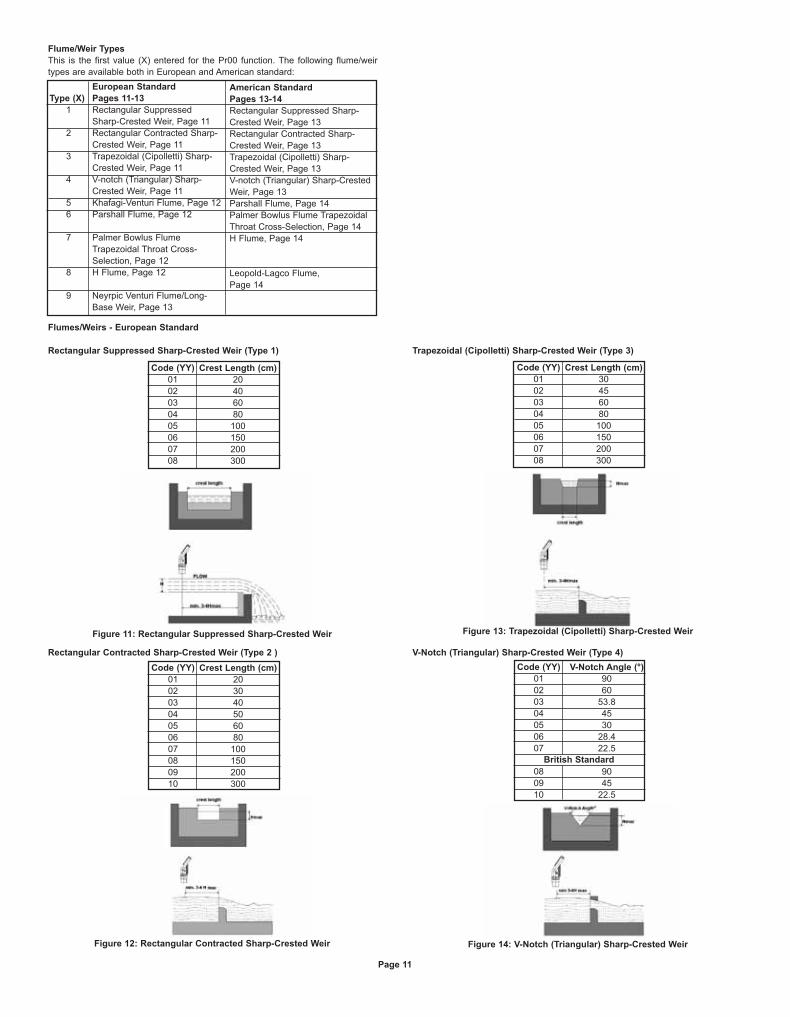
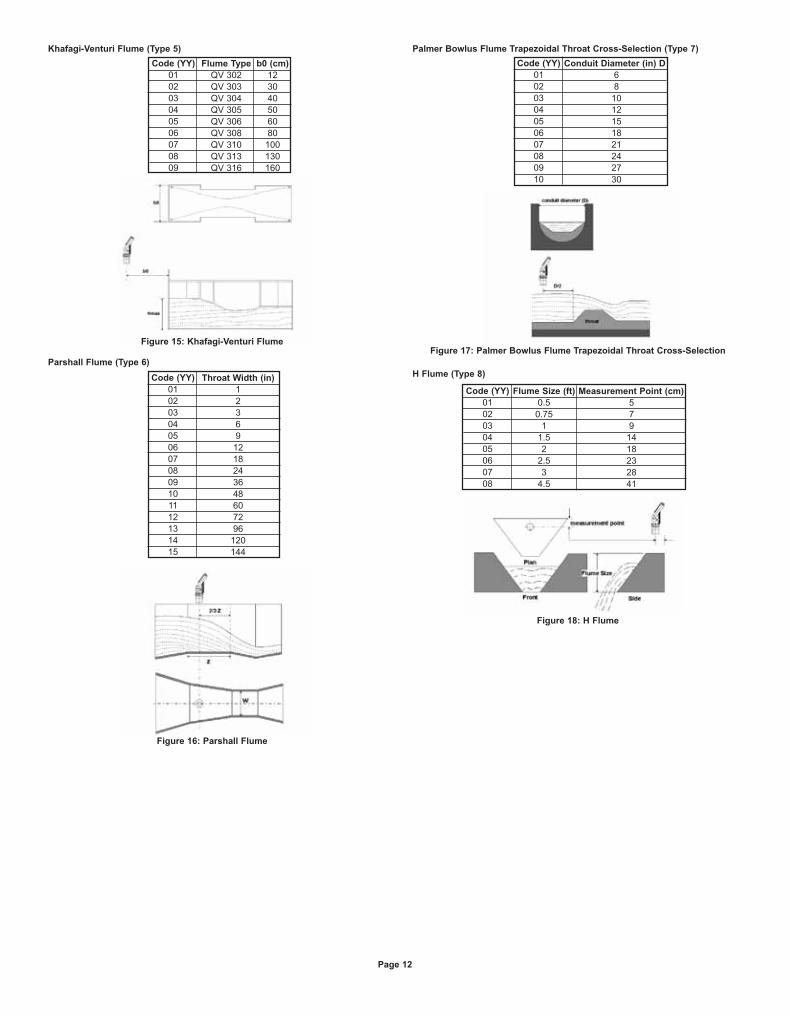
Flume/Weir Types
This is the first value (X) entered for the Pr00 function. The following flume/weir
types are available both in European and American standard: