DXair Pool Dehumidifiers MC Series 30 to 60 Tons G - 60 Galvanized The options-rich MC Model provides the DXair product lineup with a large capacity, modular unit that performs at a high level. The perfect balance of water and air.
Transcript
DXair Pool Dehumidifiers MC Series 30 to 60 TonsG-60 Galvanized
The options-rich MC Model provides the DXair product lineup
with a large capacity, modular unit that performs at a high level.
The perfect balance of water and air.
dxair.com [email protected] (800) 514-7051 Subject to change without prior notice Revised 05-16
MC SERIES POOL DEHUMIDIFIERS
2
TABLE OF CONTENTS
PERFORMANCE DATA ............................................................3EFFICIENCY AND ENVIRONMENTALLY FRIENDLY ...............3DXAIR POOL DEHUMIDIFIERS ...............................................4
About DXair in North America .....................................4MC MODEL .............................................................................5
MC MODEL 360-720 ...............................................................6UNIT CONFIGURATIONS ........................................................6
Vertical High – Horizontal Discharge ...........................6Vertical Low – Top & Front Discharge ..........................7
FEATURES, FUNCTIONS AND BENEFITS ...............................8Cabinet, Casing and Frame ..........................................8Filter Racks ......................................................................8Blower Housing and Motors .........................................8Evaporator Coil ...............................................................8Refrigerant Circuit ..........................................................9
UNIT PROTECTION MODULE (UPM) ...................................10UPM Control Board Features ......................................10
ADDITIONAL FEATURES .....................................................11Water Connections .......................................................11
ADDITIONAL OPTIONS .......................................................11Energy Management Switch (EMS) ...........................11Hot Gas Reheat .............................................................11Hot Gas Reheat Sequence of Operation – On/Off Control ..............................................................12Hot Gas Reheat Control Options Special Considerations .................................................12
TYPICAL UNIT INSTALLATION ............................................13Unit Location ................................................................13Vertical Unit Installation ..............................................13Ductwork and Sound Attenuation Considerations ..13
ELECTRICAL DATA ................................................................21BLOWER MOTOR PERFORMANCE......................................22
Belt Drive Motor ...........................................................22Air Side Pressure Drop .................................................22
BLOWER CURVE DATA .........................................................23PHYSICAL DATA ....................................................................24MODULE OPERATING WEIGHTS (LBS) ...............................25SOUND DATA ........................................................................25UNIT DIMENSIONS ...............................................................26
Vertical High Configuration ........................................26Vertical Low Configuration .........................................27
Duct Air Delivery System..............................................31
dxair.com [email protected] (800) 514-7051 Subject to change without prior notice Revised 05-16
MC SERIES POOL DEHUMIDIFIERS
3
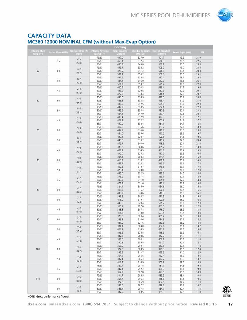
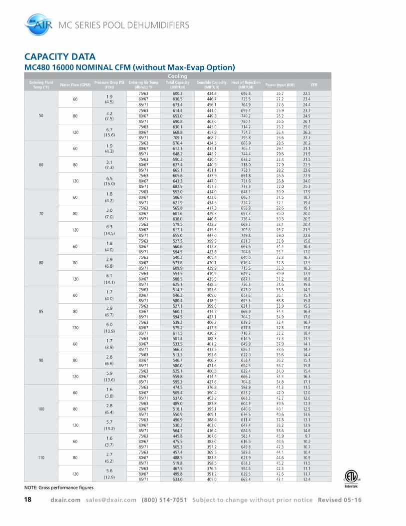
PERFORMANCE (w/ fan & pump pwr)
Model GPM CFMCooling 86º F
CAP EER
MC360 90 12,000 395,246 13.1
MC480 120 16,000 555,796 16.1
MC600 150 20,000 642,387 15.4
MC720 180 24,000 790,649 13.1
PERFORMANCE DATA
EFFICIENCY AND ENVIRONMENTALLY FRIENDLYWith the MC Model, DXair can satisfy your needs up to 200 tons with these large R-410A capacity units. The MC unit is available from 30 to 60 nominal tons in two-stage or four-stage compressor configurations. These highly efficient units not only will reduce your operating costs but play their part in reducing CO2 emissions.
4
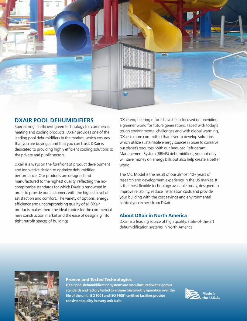
DXAIR POOL DEHUMIDIFIERSSpecializing in efficient green technology for commercial heating and cooling products, DXair provides one of the leading pool dehumidifiers in the market, which ensures that you are buying a unit that you can trust. DXair is dedicated to providing highly efficient cooling solutions to the private and public sectors.
DXair is always on the forefront of product development and innovative design to optimize dehumidifier performance. Our products are designed and manufactured to the highest quality, reflecting the no-compromise standards for which DXair is renowned in order to provide our customers with the highest level of satisfaction and comfort. The variety of options, energy efficiency and uncompromising quality of all DXair products makes them the ideal choice for the commercial new construction market and the ease of designing into tight retrofit spaces of buildings.
DXair engineering efforts have been focused on providing a greener world for future generations. Faced with today’s tough environmental challenges and with global warming, DXair is more committed than ever to develop solutions which utilize sustainable energy sources in order to conserve our planet’s resources. With our Reduced Refrigerant Management System (RRMS) dehumidifiers, you not only will save money on energy bills but also help create a better world.
The MC Model is the result of our almost 40+ years of research and development experience in the US market. It is the most flexible technology available today, designed to improve reliability, reduce installation costs and provide your building with the cost savings and environmental control you expect from DXair.
About DXair in North AmericaDXair is a leading source of high quality, state-of-the-art dehumidification systems in North America.
4
Proven and Tested Technologies DXair pool dehumidification systems are manufactured with rigorous standards and factory tested to ensurie trustworthy operation over the life of the unit. ISO 9001 and ISO 14001 certified facilities provide consistent quality in every unit built.
dxair.com [email protected] (800) 514-7051 Subject to change without prior notice Revised 05-16
MC SERIES POOL DEHUMIDIFIERS
5
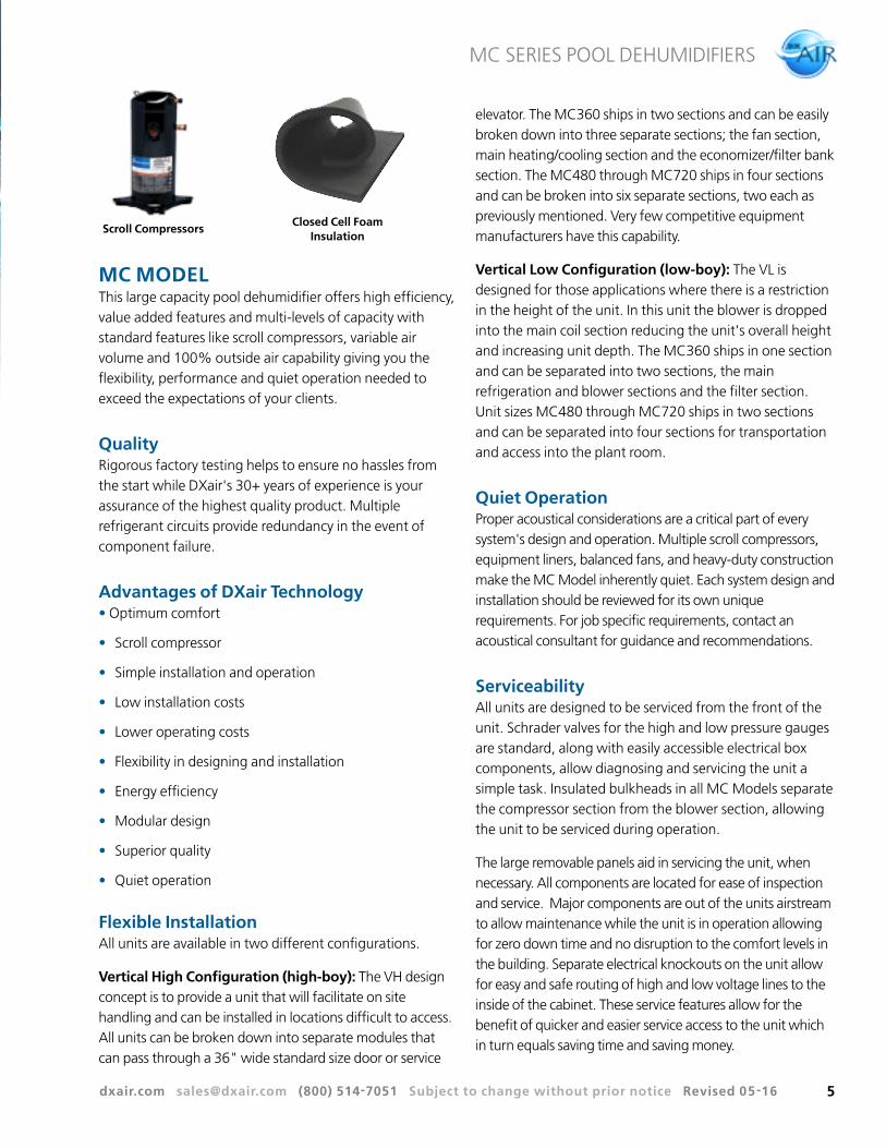
MC MODELThis large capacity pool dehumidifier offers high efficiency, value added features and multi-levels of capacity with standard features like scroll compressors, variable air volume and 100% outside air capability giving you the flexibility, performance and quiet operation needed to exceed the expectations of your clients.
QualityRigorous factory testing helps to ensure no hassles from the start while DXair's 30+ years of experience is your assurance of the highest quality product. Multiple refrigerant circuits provide redundancy in the event of component failure.
Advantages of DXair Technology• Optimum comfort
• Scroll compressor
• Simple installation and operation
• Low installation costs
• Lower operating costs
• Flexibility in designing and installation
• Energy efficiency
• Modular design
• Superior quality
• Quiet operation
Flexible InstallationAll units are available in two different configurations.
Vertical High Configuration (high-boy): The VH design concept is to provide a unit that will facilitate on site handling and can be installed in locations difficult to access. All units can be broken down into separate modules that can pass through a 36" wide standard size door or service
elevator. The MC360 ships in two sections and can be easily broken down into three separate sections; the fan section, main heating/cooling section and the economizer/filter bank section. The MC480 through MC720 ships in four sections and can be broken into six separate sections, two each as previously mentioned. Very few competitive equipment manufacturers have this capability.
Vertical Low Configuration (low-boy): The VL is designed for those applications where there is a restriction in the height of the unit. In this unit the blower is dropped into the main coil section reducing the unit's overall height and increasing unit depth. The MC360 ships in one section and can be separated into two sections, the main refrigeration and blower sections and the filter section. Unit sizes MC480 through MC720 ships in two sections and can be separated into four sections for transportation and access into the plant room.
Quiet Operation Proper acoustical considerations are a critical part of every system's design and operation. Multiple scroll compressors, equipment liners, balanced fans, and heavy-duty construction make the MC Model inherently quiet. Each system design and installation should be reviewed for its own unique requirements. For job specific requirements, contact an acoustical consultant for guidance and recommendations.
Serviceability All units are designed to be serviced from the front of the unit. Schrader valves for the high and low pressure gauges are standard, along with easily accessible electrical box components, allow diagnosing and servicing the unit a simple task. Insulated bulkheads in all MC Models separate the compressor section from the blower section, allowing the unit to be serviced during operation.
The large removable panels aid in servicing the unit, when necessary. All components are located for ease of inspection and service. Major components are out of the units airstream to allow maintenance while the unit is in operation allowing for zero down time and no disruption to the comfort levels in the building. Separate electrical knockouts on the unit allow for easy and safe routing of high and low voltage lines to the inside of the cabinet. These service features allow for the benefit of quicker and easier service access to the unit which in turn equals saving time and saving money.
Closed Cell Foam Insulation
Scroll Compressors
dxair.com [email protected] (800) 514-7051 Subject to change without prior notice Revised 05-16
MC SERIES POOL DEHUMIDIFIERS
6
UNIT CONFIGURATIONS
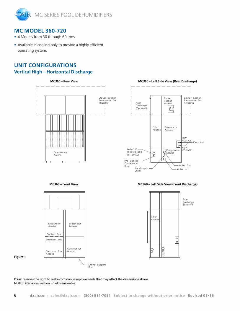
MC MODEL 360-720• 4 Models from 30 through 60 tons
• Available in cooling only to provide a highly efficient operating system.
Vertical High – Horizontal Discharge
MC360 – Rear View
MC360 – Front View
MC360 – Left Side View (Rear Discharge)
MC360 – Left Side View (Front Discharge)
Figure 1
DXair reserves the right to make continuous improvements that may affect the dimensions above. NOTE: Filter access section is field removable.
dxair.com [email protected] (800) 514-7051 Subject to change without prior notice Revised 05-16
MC SERIES POOL DEHUMIDIFIERS
7
UNIT CONFIGURATIONSVertical Low – Top & Front Discharge
MC360 – Rear View
MC360 – Front View
MC360 – Left Side View (Top Discharge)
MC360 – Left Side View (Front Discharge)
Figure 2
DXair reserves the right to make continuous improvements that may affect the dimensions above. NOTE: Filter access section is field removable.
dxair.com [email protected] (800) 514-7051 Subject to change without prior notice Revised 05-16
MC SERIES POOL DEHUMIDIFIERS
8
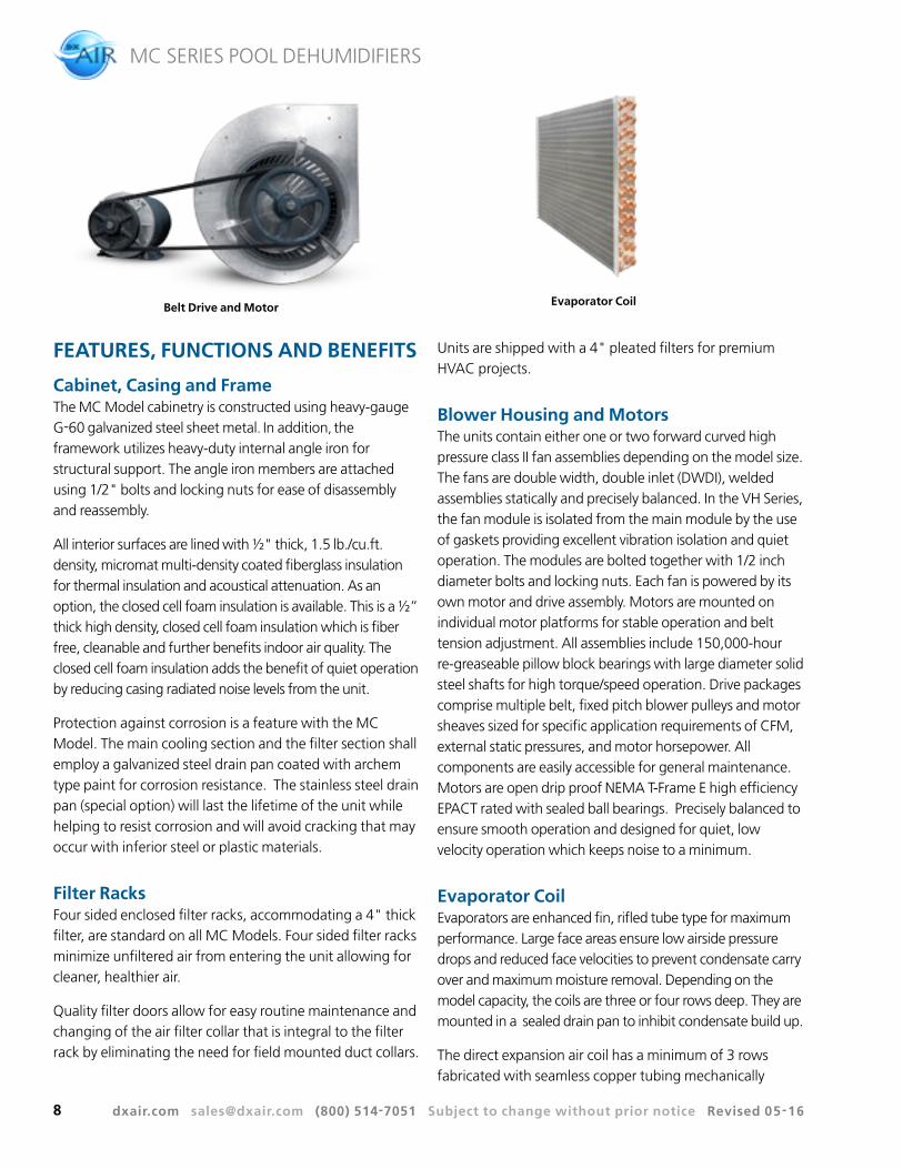
Evaporator Coil
FEATURES, FUNCTIONS AND BENEFITS
Cabinet, Casing and Frame The MC Model cabinetry is constructed using heavy-gauge G-60 galvanized steel sheet metal. In addition, the framework utilizes heavy-duty internal angle iron for structural support. The angle iron members are attached using 1/2" bolts and locking nuts for ease of disassembly and reassembly.
All interior surfaces are lined with ½" thick, 1.5 lb./cu.ft. density, micromat multi-density coated fiberglass insulation for thermal insulation and acoustical attenuation. As an option, the closed cell foam insulation is available. This is a ½” thick high density, closed cell foam insulation which is fiber free, cleanable and further benefits indoor air quality. The closed cell foam insulation adds the benefit of quiet operation by reducing casing radiated noise levels from the unit.
Protection against corrosion is a feature with the MC Model. The main cooling section and the filter section shall employ a galvanized steel drain pan coated with archem type paint for corrosion resistance. The stainless steel drain pan (special option) will last the lifetime of the unit while helping to resist corrosion and will avoid cracking that may occur with inferior steel or plastic materials.
Filter RacksFour sided enclosed filter racks, accommodating a 4" thick filter, are standard on all MC Models. Four sided filter racks minimize unfiltered air from entering the unit allowing for cleaner, healthier air.
Quality filter doors allow for easy routine maintenance and changing of the air filter collar that is integral to the filter rack by eliminating the need for field mounted duct collars.
Units are shipped with a 4" pleated filters for premium HVAC projects.
Blower Housing and MotorsThe units contain either one or two forward curved high pressure class II fan assemblies depending on the model size. The fans are double width, double inlet (DWDI), welded assemblies statically and precisely balanced. In the VH Series, the fan module is isolated from the main module by the use of gaskets providing excellent vibration isolation and quiet operation. The modules are bolted together with 1/2 inch diameter bolts and locking nuts. Each fan is powered by its own motor and drive assembly. Motors are mounted on individual motor platforms for stable operation and belt tension adjustment. All assemblies include 150,000-hour re-greaseable pillow block bearings with large diameter solid steel shafts for high torque/speed operation. Drive packages comprise multiple belt, fixed pitch blower pulleys and motor sheaves sized for specific application requirements of CFM, external static pressures, and motor horsepower. All components are easily accessible for general maintenance. Motors are open drip proof NEMA T-Frame E high efficiency EPACT rated with sealed ball bearings. Precisely balanced to ensure smooth operation and designed for quiet, low velocity operation which keeps noise to a minimum.
Evaporator CoilEvaporators are enhanced fin, rifled tube type for maximum performance. Large face areas ensure low airside pressure drops and reduced face velocities to prevent condensate carry over and maximum moisture removal. Depending on the model capacity, the coils are three or four rows deep. They are mounted in a sealed drain pan to inhibit condensate build up.
The direct expansion air coil has a minimum of 3 rows fabricated with seamless copper tubing mechanically
Belt Drive and Motor
dxair.com [email protected] (800) 514-7051 Subject to change without prior notice Revised 05-16
MC SERIES POOL DEHUMIDIFIERS
9
bonded to rippled and corrugated aluminum fins. Each individual evaporator coil shall be removable for replacement without disturbing the remaining refrigerant circuits. Each evaporator coil circuit shall be fed by an adjustable TXV, with external equalizer, sized to provide efficient operation at full and at part load operating points in the cooling and heating modes.
Refrigerant CircuitMC Models are designed using the optimum combination of compressor, water and air coils to provide peak performance.
Each refrigerant circuit is independently piped allowing part load operation in the event of a component failure. Compressor/evaporator staging is such that air stratification is kept to a minimum. The lower evaporators on each module are staged first to keep coils wet and enhance condensate removal. In the event of an evaporator failure only the individual coil needs to be changed compared to the full face evaporators utilized by some manufacturers. All units utilize high efficiency scroll compressors. The MC360 has two compressors while the MC480 through MC720 units employ four compressors for efficient part load control, quiet operation and system redundancy. Scroll compressors are considered by many in the industry to be the best in durability and efficiency. Standard in all MC Models, this ensures that each unit will be equipped to give many years of trustworthy performance.
Each compressor has its own independent refrigerant circuit and is protected by individual branch fusing. Additional protection is provided by thermal overloads and high and low pressure safety switches. Suction and discharge schrader valves are provided for manifold gauge connections to facilitate servicing. Compressors are mounted on vibration isolators. The entire condensing section is isolated from the
air-handling compartment by the use of an insulated bulkhead partition designed to minimize sound transmission. Externally equalized balanced port thermostatic expansion valves are utilized for wide range refrigerant metering control. Superheat shifts are minimal from cooling operation ensuring stable operation in the cooling modes. All TXVs are factory set and are field adjustable for specific operating conditions. Reversing valves are large bodied to minimize refrigerant pressure drop. All refrigerant components are accessible from the front of the unit for service and maintenance.
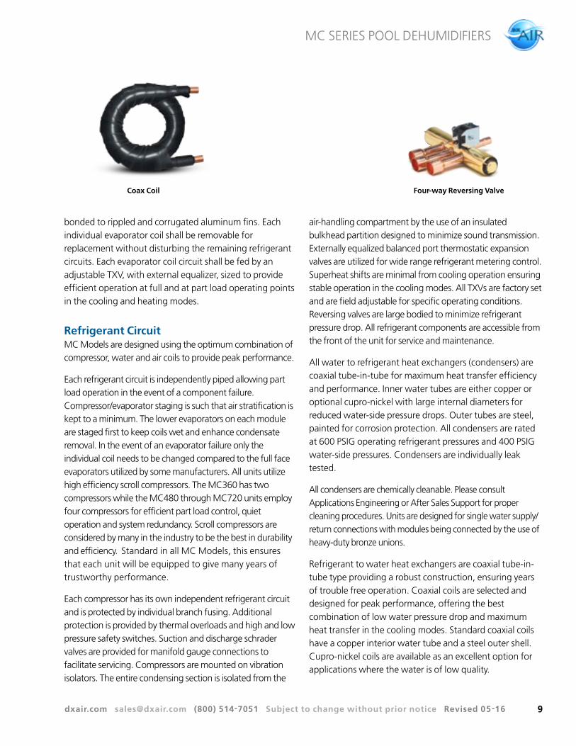
All water to refrigerant heat exchangers (condensers) are coaxial tube-in-tube for maximum heat transfer efficiency and performance. Inner water tubes are either copper or optional cupro-nickel with large internal diameters for reduced water-side pressure drops. Outer tubes are steel, painted for corrosion protection. All condensers are rated at 600 PSIG operating refrigerant pressures and 400 PSIG water-side pressures. Condensers are individually leak tested.
All condensers are chemically cleanable. Please consult Applications Engineering or After Sales Support for proper cleaning procedures. Units are designed for single water supply/return connections with modules being connected by the use of heavy-duty bronze unions.
Refrigerant to water heat exchangers are coaxial tube-in- tube type providing a robust construction, ensuring years of trouble free operation. Coaxial coils are selected and designed for peak performance, offering the best combination of low water pressure drop and maximum heat transfer in the cooling modes. Standard coaxial coils have a copper interior water tube and a steel outer shell. Cupro-nickel coils are available as an excellent option for applications where the water is of low quality.
Coax Coil Four-way Reversing Valve
dxair.com [email protected] (800) 514-7051 Subject to change without prior notice Revised 05-16
MC SERIES POOL DEHUMIDIFIERS
10
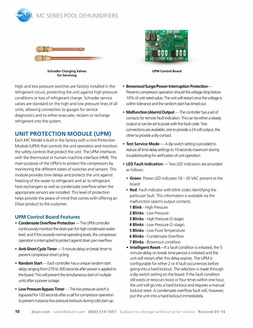
High and low pressure switches are factory installed in the refrigerant circuit, protecting the unit against high pressure conditions or loss of refrigerant charge. Schrader service valves are standard on the high and low pressure lines of all units, allowing connection to gauges for service diagnostics and to either evacuate, reclaim or recharge refrigerant into the system.
UNIT PROTECTION MODULE (UPM)Each MC Model is built in the factory with a Unit Protection Module (UPM) that controls the unit operation and monitors the safety controls that protect the unit. The UPM interfaces with the thermostat or human-machine interface (HMI). The main purpose of the UPM is to protect the compressors by monitoring the different states of switches and sensors. This module provides time delays and protects the unit against freezing of the water to refrigerant and air to refrigerant heat exchangers as well as condensate overflow when the appropriate sensors are installed. This level of protection helps provide the peace of mind that comes with offering an DXair product to the customer.
UPM Control Board Features• Condensate Overflow Protection — The UPM controller
continuously monitors the drain pan for high condensate water level, and if this exceeds normal operating levels, the compressor operation is interrupted to protect against drain pan overflow.
• Anti-Short Cycle Timer — 5 minute delay on break timer to prevent compressor short cycling.
• Random Start — Each controller has a unique random start delay ranging from 270 to 300 seconds after power is applied to the board. This will prevent the simultaneous start of multiple units after a power outage.
• Low Pressure Bypass Timer — The low pressure switch is bypassed for 120 seconds after a call for compressor operation to prevent nuisance low pressure lockouts during cold start-up.
• Brownout/Surge/Power Interruption Protection— Prevents compressor operation should the voltage drop below 10% of unit rated value. The unit will restart once the voltage is within tolerance and the random start has timed out.
• Malfunction (Alarm) Output — The controller has a set of contacts for remote fault indication. This can be either a steady output or can be set to pulse with the fault code. Two connections are available; one to provide a 24 volt output, the other to provide a dry contact.
• Test Service Mode — A dip switch setting is provided to reduce all time delay settings to 10 seconds maximum during troubleshooting for verification of unit operation.
• LED Fault Indication — Two LED indicators are provided as follows:
• Green: Power LED indicates 18 – 30 VAC present at the board.
• Red: Fault indicator with blink codes identifying the particular fault. This information is available via the malfunction (alarm) output contacts.1 Blink - High Pressure2 Blinks - Low Pressure3 Blinks - High Pressure (2-stage)4 Blinks - Low Pressure (2-stage)5 Blinks - Low Fluid Temperature6 Blinks - Condensate Overflow7 Blinks - Brownout condition
• Intelligent Reset—If a fault condition is initiated, the 5 minute delay on break time period is initiated and the unit will restart after this delay expires. The UPM is configurable for either 2 or 4 fault occurrences before going into a hard lockout. The selection is made through a dip switch setting on the board. If the fault condition still exists or reoccurs twice or four times within one hour, the unit will go into a hard lockout and requires a manual lockout reset. A condensate overflow fault will, however, put the unit into a hard lockout immediately.
UPM Control BoardSchrader Charging Valves for Servicing
dxair.com [email protected] (800) 514-7051 Subject to change without prior notice Revised 05-16
MC SERIES POOL DEHUMIDIFIERS
11
• Lockout Reset—A hard lockout can be reset by turning the unit thermostat off and then back on or by shutting off unit power at the circuit breaker. The method of reset is selectable by the dip switch on the board.
ADDITIONAL FEATURES • 100VA transformer
• Belt drive, inverter duty fan motor
- HP 7.5, 10, 15, 20
- Up to sixteen different direct drives selectable
• TXV
• Dual freeze sensor for airside and waterside
• Condensate over flow switch
• Reverse cycle
• Hot gas bypass
Water ConnectionsAll water connections are heavy-duty bronze FPT fittings.
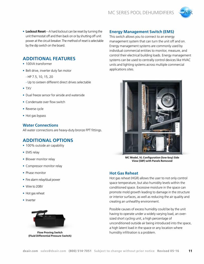
Energy Management Switch (EMS) This switch allows you to connect to an energy management system that can turn the unit off and on. Energy management systems are commonly used by individual commercial entities to monitor, measure, and control their electrical building loads. Energy management systems can be used to centrally control devices like HVAC units and lighting systems across multiple commercial applications sites.
MC Model, VL Configuration (low-boy) Side View (SBF) with Panels Removed
Hot Gas ReheatHot gas reheat (HGR) allows the user to not only control space temperature, but also humidity levels within the conditioned space. Excessive moisture in the space can promote mold growth leading to damage in the structure or interior surfaces, as well as reducing the air quality and creating an unhealthy environment.
Possible causes of excess humidity could be by the unit having to operate under a widely varying load, an over- sized short cycling unit, a high percentage of unconditioned outside air being introduced into the space, a high latent load in the space or any location where humidity infiltration is a problem.
dxair.com [email protected] (800) 514-7051 Subject to change without prior notice Revised 05-16
MC SERIES POOL DEHUMIDIFIERS
12
Typical unit control is by a wall mounted thermostat that senses temperature in the occupied space. By utilizing a humidistat in addition to the thermostat, we are able to monitor the humidity levels in the space as well. The HGR option allows cooling and dehumidification to satisfy both the thermostat and humidistat while preventing over cooling of the space while in the dehumidification mode.
Once the thermostat reaches set point temperature and the humidity is above set point, the unit controller will energize the reheat valve operating the unit in hot gas reheat mode, first cooling and dehumidifying, then reheating the air using hot refrigerant gas before delivering it to the space. By reheating the air along a constant sensible heat line, the relative humidity of the leaving air is reduced. This option offers significant energy savings over the traditional means of reheating air with electric heating coils.
A hot gas reheat valve and a reheat coil are included in the refrigerant circuit.
In the reheat mode, the compressor discharge gas is diverted through the reheat valve to the reheat coil which is located downstream of the cooling coil. The superheated refrigerant gas reheats the air leaving the cooling coil. The hot refrigerant gas then passes though the water to refrigerant coil where it is condensed to a liquid. From this point the rest of the cooling cycle is completed. There are two check valves to prevent refrigerant flow into the reheat coil during standard cooling cycles. A small copper bleeder line is connected to the outlet line of the reheat coil and between the expansion valve outlet and distributor to the air coil. This line is necessary to let any liquid/oil that may have migrated to the reheat coil during reheat to escape during standard cooling modes.
Hot Gas Reheat Control Options Included
Special ConsiderationsSome applications require special attention to maximize the performance of the hot gas reheat function:
• Indoor Pool Dehumidifying During Winter Months (Re: Heating Mode)
Consult DXair for special application considerations.
Caution Protective Bronze Glow coatings are highly
recommended for all pool applications, due to
the highly corrosive chemical environment.
dxair.com [email protected] (800) 514-7051 Subject to change without prior notice Revised 05-16
MC SERIES POOL DEHUMIDIFIERS
13
TYPICAL UNIT INSTALLATION
Unit LocationAny mechanical device will, at some point in time, require servicing and repair. With this in mind, sufficient space must be provided around the unit for service personnel to perform maintenance or repair.
Units are not designed for outdoor installation. Avoid locations where the unit may be exposed to freezing conditions or where the humidity levels could cause condensation on the unit panels for example when exposed to outdoor ambient conditions.
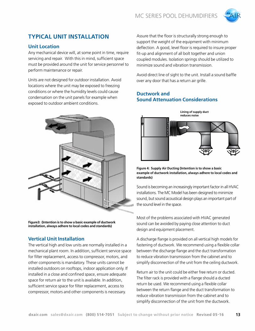
Figure3: (Intention is to show a basic example of ductwork installation, always adhere to local codes and standards)
Vertical Unit InstallationThe vertical high and low units are normally installed in a mechanical plant room. In addition, sufficient service space for filter replacement, access to compressor, motors, and other components is mandatory. These units cannot be installed outdoors on rooftops, indoor application only. If installed in a close and confined space, ensure adequate space for return air to the unit is available. In addition, sufficient service space for filter replacement, access to compressor, motors and other components is necessary.
Assure that the floor is structurally strong enough to support the weight of the equipment with minimum deflection. A good, level floor is required to insure proper fit-up and alignment of all bolt together and union coupled modules. Isolation springs should be utilized to minimize sound and vibration transmission.
Avoid direct line of sight to the unit. Install a sound baffle over any door that has a return air grille.
Ductwork and Sound Attenuation Considerations
Lining of supply duct reduces noise
Figure 4: Supply Air Ducting (Intention is to show a basic example of ductwork installation, always adhere to local codes and standards)
Sound is becoming an increasingly important factor in all HVAC installations. The MC Model has been designed to minimize sound, but sound acoustical design plays an important part of the sound level in the space.
Most of the problems associated with HVAC generated sound can be avoided by paying close attention to duct design and equipment placement.
A discharge flange is provided on all vertical high models for fastening of ductwork. We recommend using a flexible collar between the discharge flange and the duct transformation to reduce vibration transmission from the cabinet and to simplify disconnection of the unit from the ceiling ductwork.
Return air to the unit could be either free return or ducted. The filter rack is provided with a flange should a ducted return be used. We recommend using a flexible collar between the return flange and the duct transformation to reduce vibration transmission from the cabinet and to simplify disconnection of the unit from the ductwork.
dxair.com [email protected] (800) 514-7051 Subject to change without prior notice Revised 05-16
MC SERIES POOL DEHUMIDIFIERS
14
Sound is transmitted down the ductwork and it is important to avoid direct line of sight between the unit and the space, both on the return or supply side. To accomplish this, design the duct runs with two 90° turns.
As a general recommendation, duct interiors should have an acoustic / thermal lining of least 1/2" thick over the entire duct run or a minimum of the first 5 feet of the supply trunk.
Line the last five diameters of duct before each outlet with a one-inch thick sound blanket. Line elbows and transition pieces, as well as a short distance upstream and downstream of the fittings.
Elbows, tees and dampers can create turbulence or distortion in the airflow. Using aerodynamic fittings will help in reducing this effect. Place a straight length of duct, 5 to 10 times the duct width, before the next fitting to smooth out airflow.
Diffusers that are located in the bottom of a trunk duct can also produce noise.
Balancing dampers should be located several duct widths upstream from an air outlet.
Ductwork should be mounted and supported using isolation devices that absorb vibration.
PIPING
Condensate Drain PipingCondensate piping can be made of steel, copper or PVC pipe. In most cases, PVC pipe eliminates the need to wrap insulation around the pipe to prevent sweating.
A condensate drain connection is installed in the unit. The condensate piping must be trapped at the unit and pitched away from the unit not less than ¼" per foot. A vent is required after the trap so that the condensate will drain away from the unit. The vent can also act as a cleanout if the trap becomes clogged. The condensate drain should not be directly piped to a drain/waste/vent stack. See local codes for the correct application of condensate piping to drains.
Caution Do not install any system above electrical
raceways or plumbing or areas that may be
affected by noise levels of operation.
OPERATING LIMITSThe MC Models are capable of operating over a wide range of conditions.
• Maximum and minimum fluid conditions are at unit rated flow rate.
• Maximum and minimum operating limits may not be combined. If one value is at either maximum or minimum, the other two should be at normal operating range.
EQUIPMENT SELECTION To ensure that you get the optimal performance from your DXair pool dehumidifier, it is important that they be selected accurately to match your design conditions.
Prior to making equipment selections the zone conditions need to be determined. DXair recommends using a building load program to determine the heating and cooling loads and providing the sensible calculations to DXair engineering for review and sizing.
dxair.com [email protected] (800) 514-7051 Subject to change without prior notice Revised 05-16
MC SERIES POOL DEHUMIDIFIERS
15
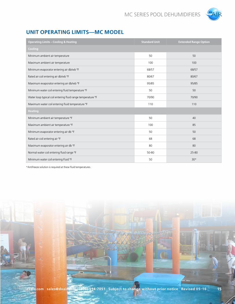
UNIT OPERATING LIMITS —MC MODEL
Operating Limits – Cooling & Heating Standard Unit Extended Range Option
Cooling
Minimum ambient air temperature 50 50
Maximum ambient air temperature 100 100
Minimum evaporator entering air db/wb °F 68/57 68/57
Rated air coil entering air db/wb °F 80/67 80/67
Maximum evaporator entering air db/wb °F 95/85 95/85
Minimum water coil entering fluid temperature °F 50 50
Water loop typical coil entering fluid range temperature °F 70/90 70/90
Maximum water coil entering fluid temperature °F 110 110
Heating
Minimum ambient air temperature °F 50 40
Maximum ambient air temperature °F 100 85
Minimum evaporator entering air db °F 50 50
Rated air coil entering air °F 68 68
Maximum evaporator entering air db °F 80 80
Normal water coil entering fluid range °F 50-80 25-80
Minimum water coil entering Fluid °F 50 30*
*Antifreeze solution is required at these fluid temperatures.
dxair.com [email protected] (800) 514-7051 Subject to change without prior notice Revised 05-16
MC SERIES POOL DEHUMIDIFIERS
16
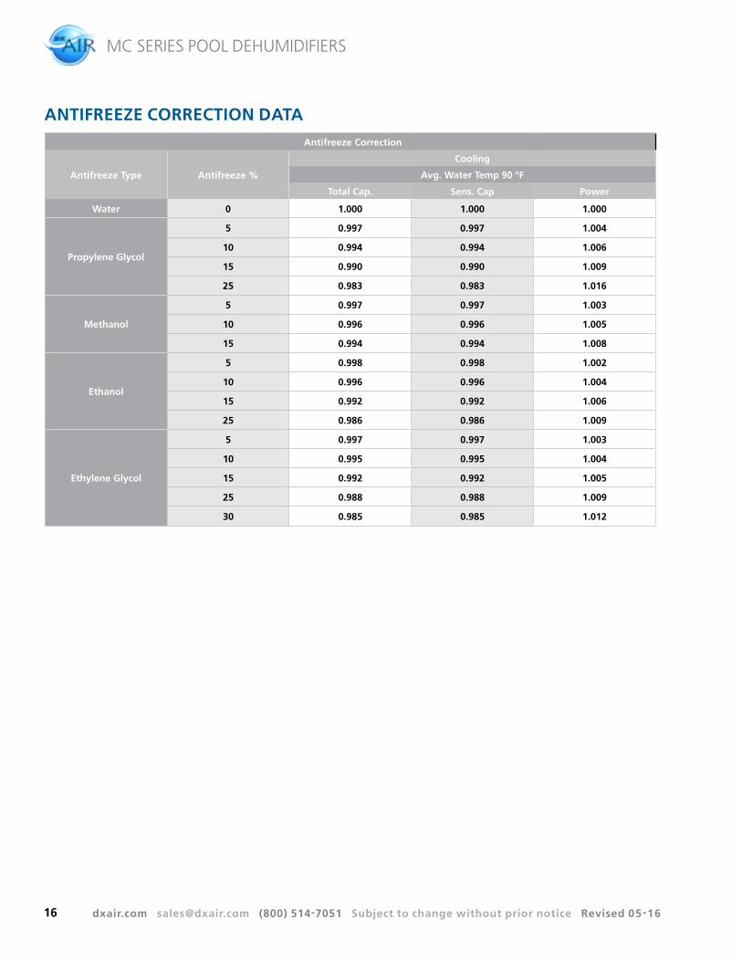
Antifreeze Correction
Antifreeze Type Antifreeze %
Cooling
Avg. Water Temp 90 °F
Total Cap. Sens. Cap Power
Water 0 1.000 1.000 1.000
Propylene Glycol
5 0.997 0.997 1.004
10 0.994 0.994 1.006
15 0.990 0.990 1.009
25 0.983 0.983 1.016
Methanol
5 0.997 0.997 1.003
10 0.996 0.996 1.005
15 0.994 0.994 1.008
Ethanol
5 0.998 0.998 1.002
10 0.996 0.996 1.004
15 0.992 0.992 1.006
25 0.986 0.986 1.009
Ethylene Glycol
5 0.997 0.997 1.003
10 0.995 0.995 1.004
15 0.992 0.992 1.005
25 0.988 0.988 1.009
30 0.985 0.985 1.012
ANTIFREEZE CORRECTION DATA
dxair.com [email protected] (800) 514-7051 Subject to change without prior notice Revised 05-16
NOTE: 1) Cooling coil shown with wet surface. 2) Reheat coil and hot water coil shown dry. 3) Filters shown clean. 65% filter is avaiable as a field-installed accessory only.
dxair.com [email protected] (800) 514-7051 Subject to change without prior notice Revised 05-16
MC SERIES POOL DEHUMIDIFIERS
23
Mo
del
G18
-13
Max
. W
hee
l RP
M1
45
0S
haf
t D
iam
eter
, In
.S
ee C
om
po
nen
t Li
mit
sM
ax.
HP
See
Co
mp
on
ent
Lim
its
Per
form
ance
sho
wn is
fo
r in
stal
lati
on T
ype
B: Fr
eein
let,
duc
ted
out
let.
Po
wer
rat
ing
bhp
do
es n
ot
incl
ude
tran
smis
sio
n lo
sses
.P
erfo
rman
ce r
atin
gs d
o n
ot
incl
ude
the
effe
cts
of
app
urte
nan
ces
(acc
esso
ries
).
Static Pressure (In. wg)
Volu
me
(CFM
wit
h 00
0's
omit
ted
)
.00
.50
1.00
1.50
2.00
2.50
3.00
3.50
4.00
01
23
45
67
89
1011
12
SystemCurve(s)
3/4HP
1
1-1/2
2
3
5
7-1/2
10
300RPM
400
500
600
700
800
90010001100
BLOWER CURVE DATA
Figure 5
dxair.com [email protected] (800) 514-7051 Subject to change without prior notice Revised 05-16
MC SERIES POOL DEHUMIDIFIERS
24
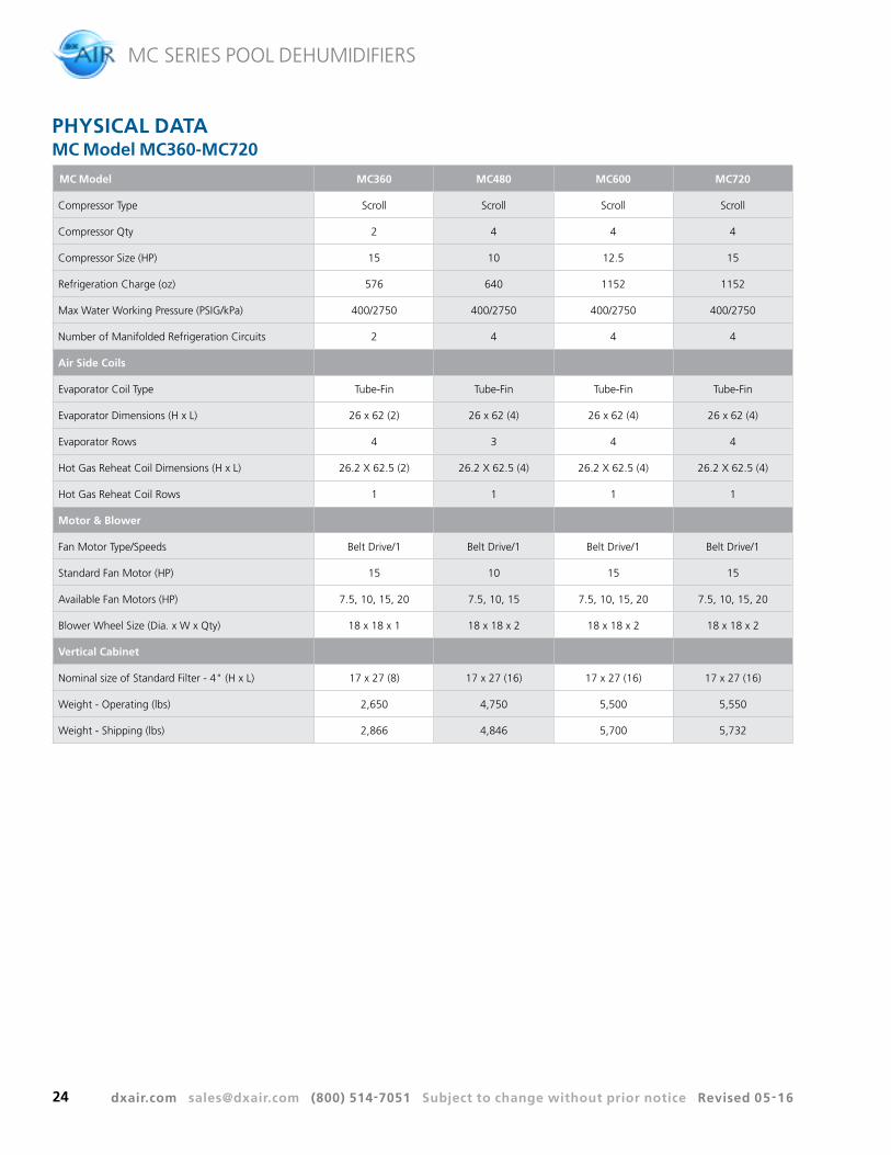
MC Model MC360 MC480 MC600 MC720
Compressor Type Scroll Scroll Scroll Scroll
Compressor Qty 2 4 4 4
Compressor Size (HP) 15 10 12.5 15
Refrigeration Charge (oz) 576 640 1152 1152
Max Water Working Pressure (PSIG/kPa) 400/2750 400/2750 400/2750 400/2750
Number of Manifolded Refrigeration Circuits 2 4 4 4
Air Side Coils
Evaporator Coil Type Tube-Fin Tube-Fin Tube-Fin Tube-Fin
Evaporator Dimensions (H x L) 26 x 62 (2) 26 x 62 (4) 26 x 62 (4) 26 x 62 (4)
Evaporator Rows 4 3 4 4
Hot Gas Reheat Coil Dimensions (H x L) 26.2 X 62.5 (2) 26.2 X 62.5 (4) 26.2 X 62.5 (4) 26.2 X 62.5 (4)
Hot Gas Reheat Coil Rows 1 1 1 1
Motor & Blower
Fan Motor Type/Speeds Belt Drive/1 Belt Drive/1 Belt Drive/1 Belt Drive/1
Standard Fan Motor (HP) 15 10 15 15
Available Fan Motors (HP) 7.5, 10, 15, 20 7.5, 10, 15 7.5, 10, 15, 20 7.5, 10, 15, 20
Blower Wheel Size (Dia. x W x Qty) 18 x 18 x 1 18 x 18 x 2 18 x 18 x 2 18 x 18 x 2
Vertical Cabinet
Nominal size of Standard Filter - 4" (H x L) 17 x 27 (8) 17 x 27 (16) 17 x 27 (16) 17 x 27 (16)
Weight - Operating (lbs) 2,650 4,750 5,500 5,550
Weight - Shipping (lbs) 2,866 4,846 5,700 5,732
PHYSICAL DATAMC Model MC360-MC720
dxair.com [email protected] (800) 514-7051 Subject to change without prior notice Revised 05-16
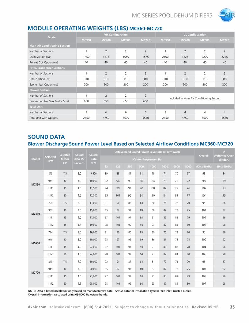
NOTE: Data is based on blower only based on manufacturer's data. AMCA data for installation Type B: Free inlet, Ducted outlet. Overall information calculated using 63-8000 Hz octave bands.
dxair.com [email protected] (800) 514-7051 Subject to change without prior notice Revised 05-16
MC SERIES POOL DEHUMIDIFIERS
26
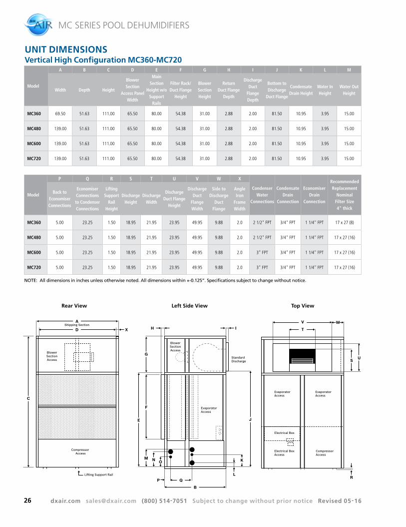
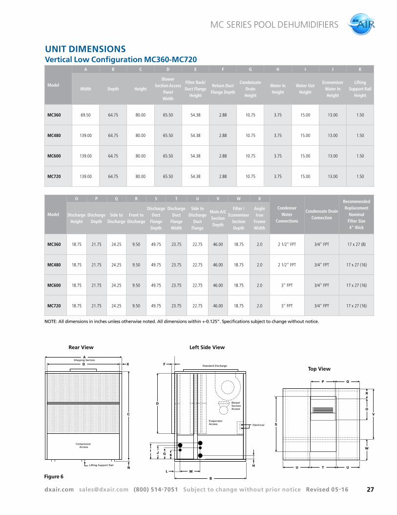
UNIT DIMENSIONSVertical High Configuration MC360-MC720
NOTE: All dimensions in inches unless otherwise noted. All dimensions within +-0.125”. Specifications subject to change without notice.
S
V
O
W
R
U T U
P Q
Standard Discharge
EvaporatorAccess Electrical
BlowerSectionAccess
F
L
D
M
B
J G K
H
I
A
C
N
Shipping Section
Compressor Access
Lifting Support Rail
D X
Rear View Left Side View
Top View
Figure 6
dxair.com [email protected] (800) 514-7051 Subject to change without prior notice Revised 05-16
MC SERIES POOL DEHUMIDIFIERS
28
GUIDE SPECIFICATIONSGeneral
Furnish and install where shown on plans, MC Model self-contained packaged air conditioning unit. Capacities, models and unit arrangement shall be as shown on the unit schedule and the contract drawings. All units shall conform to UL1995 standard and be certified to CAN/CSA C22.1 No 236 by Intertek-ETL. Unit shall be accepted for use in the City of New York by the Department of Buildings (MEA). Each unit shall be completely factory assembled, piped, wired and tested. Units shall be leak tested and charged with a full operating charge of Refrigerant 410A. Units shall then be disassembled into their individual modules for shipping and assembly on site. Installation and maintenance manuals and wiring diagrams shall be supplied with each unit. Factory test shall include, but not be limited to: complete run check of all electrical components and safeties, including proper control sequencing; pressure test of refrigerant coils and condensers; leak check of completed refrigerant circuits; leak check of completed water circuit; compressor run check.
Cabinet
VH CONFIGURATION: The unit shall be comprised of three distinct modules: 1) Main cooling, 2) Filter, and 3) Fan section. The unit shall be designed for ease of assembly. The refrigeration circuit shall remain intact during disassembly/assembly. All modules shall be able to pass through a 36" steel framed door. The frame shall be fabricated of an angle iron framework. Unit exterior panels shall be 18 gauge G-60 galvanized steel for corrosion protection. Each section shall incorporate removable access panels. The complete cabinet frame and access panels shall be insulated with ½", 1.5lb dual density fiberglass insulation. The main cooling section and the filter section shall contain a galvanized steel drain pan coated with archem type paint for corrosion resistance.
VL CONFIGURATION: The unit shall be comprised of two distinct modules: 1) Main cooling section with blower(s) and motor(s) 2) Filter section. The unit shall be designed for ease of assembly. The refrigeration circuit shall remain intact during disassembly/assembly. The frame shall be fabricated of an angle iron framework. Unit exterior panels shall be G-60 galvanized steel. Each section shall incorporate removable access panels. The complete cabinet frame and access panels shall be insulated with ½", 1.5lb dual density
fiberglass insulation. The main cooling section and the filter section shall contain a galvanized steel drain pan coated with archem type paint for corrosion resistance.
Offered as an option, ½" thick, closed cell foam insulation shall promote the indoor air quality (IAQ) of commercial buildings by improving moisture management and sound control.
Evaporator
The direct expansion coil shall be a minimum of 3 rows and fabricated from 3/8" or ½" O.D. seamless copper tubing mechanically bonded to rippled and corrugated aluminum fins. Each individual evaporator coil shall be removable for replacement without disturbing the remaining refrigerant circuits. Each evaporator coil circuit shall be fed by an adjustable thermostatic expansion valve, with external equalizer, sized to provide efficient operation at full and at part load operating points in the cooling modes.
Supply Fan
Supply fans shall be double width, double inlet forward curved type of Class II construction. All fans shall be statically and dynamically balanced. Fan shafts shall be mounted in heavy-duty 150,000 hour greaseable pillow block bearings. The fan motor shall be open drip proof three phase, NEMA T frame E high efficiency EPACT rated, 1800 rpm, with grease lubricated ball bearings. The drive shall include fixed pitch sheaves with multiple V belts sized for 115% of the fan brake horsepower.
Refrigeration Circuit
Each unit shall contain multiple independent refrigeration circuits. Each circuit shall include a high efficiency heavy-duty scroll compressors. Each circuit shall have high and low pressure cutouts. Each circuit shall be factory sealed and fully charged with Refrigerant 410A. Suction and discharge schrader valves shall be provided for manifold gauge connections to facilitate servicing.
Compressors
Each unit shall have multiple high efficiency scroll compressors with internal or external motor protection and a time delay to prevent short cycling and simultaneous starting of compressors following a power failure. Each
dxair.com [email protected] (800) 514-7051 Subject to change without prior notice Revised 05-16
MC SERIES POOL DEHUMIDIFIERS
29
GUIDE SPECIFICATIONScompressor shall be on an independent refrigerant circuit. The compressors shall be mounted on rubber isolators.
Condensers
All condensers shall be coaxial tube-in-tube for maximum heat transfer efficiency and performance. Inner water tubes shall be either copper or optional cupro-nickel with large internal diameters for reduced waterside pressure drops. Outer tubes shall be steel, painted for corrosion protection. All condensers shall be rated at 600 PSIG operating refrigerant pressures and 400 PSIG waterside pressures.
Hot Gas Reheat
Provide a hot gas reheat coil to allow the unit to operate in the dehumidification mode without overheating the space. Control of the hot gas reheat shall be conducted by the unit controller with a humidity sensor that has a digital output to activate the reheat valve.
Filter Section
The unit shall be supplied with 4" deep pleated, 30% high efficiency filters. The filters shall have side access capability through an access panel.
Electrical
Each unit shall be wired and tested at the factory prior to shipment. Wiring shall comply with NEC requirements and shall conform with all applicable ETL standards. The units shall have a single point power connection. The control power shall be supplied through a factory installed, low voltage control circuit transformer with an integral resettable circuit breaker. The fan motor starter shall have at magnetic three line, ambient compensated overload protector with a manual reset. A terminal block shall be provided for the main power connection.
Each unit shall be provided with a Unit Protection Module (UPM) that controls compressor operation and monitors the safety controls that protect the unit.
Safety controls include the following:
High pressure switches located in the refrigerant discharge lines. One per refrigeration unit.
Low pressure switches for loss of charge protection located in the unit refrigerant suction lines. One per refrigeration unit.
Condensate overflow protection sensor located in the drain pan(s) of the unit and wired to the UPM board.
The UPM includes the following features:
Anti-Short Cycle Timer: 5 minute delay on break timer to prevent compressor short cycling.
Random Start: Each controller has a unique random start delay ranging from 270 to 300 seconds.
Low Pressure Bypass Timer: The low pressure switch will be bypassed for 120 seconds after compressor start-up to prevent nuisance low pressure lockouts during cold start-up.
Brownout/Surge/Power Interruption Protection: A 20 millisecond window is to be monitored for the above condition. Should any of these conditions be detected, the 5-minute delay on break timer and the random start timer delay are initiated.
Malfunction Output: The controller shall have a set of wet contacts for remote fault indication.
LED Fault Indication: Two LED indicators are provided as follows:
• Green: Power LED indicates 18 – 30 VAC present at the board.
• Red: Fault indicator with blink codes as follows:
• One Blink: 1st Stage high pressure lockout
• Two Blinks: 1st Stage low pressure lockout
• Three Blinks: 2nd Stage high pressure lockout
• Four Blinks: 2nd Stage low pressure lockout
• Five Blinks: Freeze protection lockout
• Six Blinks: Condensate overflow lockout
• Seven Blinks: Brown Out
dxair.com [email protected] (800) 514-7051 Subject to change without prior notice Revised 05-16
MC SERIES POOL DEHUMIDIFIERS
30
GUIDE SPECIFICATIONS Intelligent Reset: If a fault condition is initiated, the 5 minute delay on break time period is initiated and the unit will restart after this delay expires. The UPM is configurable for either 2 or 4 fault occurrences before going into a hard lockout. The selection is made through a dip switch setting on the board. If the fault condition still exists or reoccurs twice or four times within one hour, the unit will go into a hard lockout and requires a manual lockout reset. A condensate overflow fault will, however, put the unit into a hard lockout immediately.
Lockout Reset: A hard lockout can be reset by turning the unit thermostat off and then back on or by shutting off unit power at the circuit breaker.
Caution The blower motor will remain active during a
lockout condition.
Auxiliary Control Options (Optional)
A pressure differential type water flow switch shall be provided, factory installed, to verify water flow status at the unit. Compressor operation shall be disabled and an alarm signal provided if condenser water flow is lost. Unit operation will be restored when water flow has been reestablished.
DDC Controls: Unit shall be equipped with a factory installed DDC control capable of interfacing with BACnetTM, Modbus, N2 or Lon works® (with optional card).
The controller shall be preprogrammed to control the unit and monitor the safety controls.
The unit shall be able to operate as a standalone or be integrated into the building management system.
A leaving water and leaving air sensor shall be installed in the unit.
Wall sensors shall be available for controlling zone temperature.
UNIT LOCATIONDO NOT STORE pool equipment and/or pool chemicals in the mechanical space designed for the DXair Dehumidification System. Failure to follow these instructions may void your warranty as chemicals are highly corrosive and destructive to any HVAC system.
Any mechanical device will, at some point in time, require servicing and repair. With this in mind, sufficient mechanical space must be designed and sufficient clearances around each horizontal and vertical unit must be provided. 30-36” clearance is required around the unit and access panels. This equipment is not recommended to be located or installed in the pool room above an open pool, closets, crawl spaces without the proper access, “trap” door type accessible spaces. The proper space must be allocated to install the system, clearances required, peripheral installation, ductwork and bypass installation. Failure to provide the appropriate space may void your warranty.
Proper clearances for installation of peripherals and space must be allowed for the proper duct work installation. Choking down ductwork in this mechanical space will have negative air flow effects for your pool room. Sufficient space must be provided for filter replacement and access to the compressors. Units should be set on a piece of rubber, neoprene or other vibration absorbing material at least 1/3- ½” thick. The pad should extend ¾” over the entire base of the unit. Avoid direct line of sight to the unit. Install a sound baffle over any door that has a return air grille.
Horizontal units are typically suspended above the ceiling by four (field supplied) 3/8” threaded rods fastened to the unit by factory supplier hanger bracket kits. This kit includes rubber isolators to help prevent transmission of vibration and noise to the building structure. Units should be located directly below a structural member, so that it is securely anchored. A horizontal unit always requires the proper clearances (18” clearance on either side of the unit for service and 36” in the front of the unit for maintenance access). The filter needs to be slid out and sufficient space must be provided to allow this.
Do not install any unit above any piping or electrical raceways. This unit must be able to be removed at any time without major re-arrangement of other mechanical or ceiling components.
dxair.com [email protected] (800) 514-7051 Subject to change without prior notice Revised 05-16
MC SERIES POOL DEHUMIDIFIERS
31
SOUNDSound is becoming an increasingly important factor in all HVAC Installations. Most of the problems associated with HVAC generated noise can be avoided by paying close attention to the equipment placement in properly designed mechanical space and the duct work/air delivery system.
NEGATIVE PRESSUREA negative pressure fan must be installed in the pool room to prevent moisture migration. This is mandatory for all indoor pool room environments.
Duct Air Delivery SystemDXair requires a very high standard of duct systems for our equipment. All specifications for the air delivery system must be met and all ASHRAE and ACCA Manuals pertaining to properly sized duct work must be followed. Air delivery is critical to these structures. A continuous loop of duct is recommended at a .20 static on supply and a .07 on one high return air. All diffusers should be double deflection and moving air 6-12” from all glass or surfaces that are prone to condensation. Diffusers are not designed “blowing down”, “blowing over” a pool area, they must be deflected at surfaces that can reach Dew Point Temperature. Diffusers are not built into the walls between windows blowing across an open pool.
We do not recommend blowing air across an open pool ; this serves to increase the evaporation of pool water and create a chill effect on the patrons. Blowing air across an open pool does not resolve the chloramine issues; this is water quality issue not an air flow issue. Air is critical to the structure and the proper air turnover rates and air delivery system will assist in maintaining this environment properly; however, proper pool water balancing must be addressed at all times by owners/staff, and showers must be taken by all patrons prior to entering the pool. Please keep in mind, if you can smell the chemicals in a natatorium, the pool is out of balance and becomes a highly caustic and corrosive environment.
Square throats and restrictions in the air delivery system must be eliminated. If square throats are used, the proper elbows/radius and turning vanes are required. The more restrictive air flow in a duct system, the less likely this system will control the environment properly and may place additional stress due to lack of air flow on the system itself.
No fiberboard duct or flex duct should be used in these systems unless approved in writing by DXair Engineering. All skylights must be addressed with air flow. If ducting cannot reach these areas, ceiling fans blowing up must be installed between the skylights to move air into them and prevent condensation.