66
Dycor LC-Series Residual Gas Analyzer User Manual Process Instruments 150 Freeport Road Pittsburgh, PA 15238 PN 90421VE, Rev D COMMITTED TO TOTAL QUALITY Q M T

Dycor LC-SeriesResidual Gas Analyzer
User Manual
Process Instruments150 Freeport Road
Pittsburgh, PA 15238PN 90421VE, Rev D
COMMITTED TO TOTAL QUALITY
QMT

ii | Dycor LC-Series Residual Gas Analyzer
© 2001 AMETEK
This manual is a guide for the use of the Dycor LC-Series Residual Gas Analyzer. Data herein has been verified and validated and is believedadequate for the intended use of this instrument. If the instrument or procedures are used for purposes over and above the capabilitiesspecified herein, confirmation of their validity and suitability should be obtained; otherwise, AMETEK does not guarantee results and assumesno obligation or liability. This publication is not a license to operate under, or a recommendation to infringe upon, any process patents.
AMETEK Process Instruments150 Freeport RoadPittsburgh, PA 15238, USAPhone: 412-828-9040Fax: 412-826-0399
AMETEK Process Instruments455 Corporate BoulevardNewark, Delaware 19702, USAPhone: 302-456-4400 (Main)
800-537-6044 (Service)800-222-6789 (Ordering)
Fax: 302-456-4444
AMETEK Process InstrumentsAMETEK-APIE OfficePostfach 2165D-40644 Meerbusch
ORRudolf-Diesel Strasse 16D-40670 MeerbuschGermanyPhone: 49-21-59-9136-0Fax: 49-21-59-9136-39
AMETEK Process Instruments7950 Whithorn DriveHouston, Texas 77095, USAPhone: 281-463-2820Fax: 281-463-2701
AMETEK Singapore PVT. Ltd.10 Ang Mo Kio Street 65#05-12 TechpointSingapore 569059Republic of SingaporePhone: 65-484-2388Fax: 65-481-6588
AMETEK Process InstrumentsWestern Research2876 Sunridge Way N.E.Calgary, AlbertaCanada T1Y 7H9Phone: 403-235-8400Fax: 403-248-3550
Offices

| iii
Table ofContents
CHAPTER 1 OVERVIEWDycor LC Series Mass Spectrometer ............................................................. 1-1
LC Series System ........................................................................................ 1-1Options for LC Series System .................................................................. 1-1
Mass Spectrometer Theory.............................................................................. 1-2Mass Spectrometer Hardware .................................................................. 1-2
Ionization .............................................................................................. 1-3EI ionization ......................................................................................... 1-3Separation ............................................................................................. 1-3Detection ............................................................................................... 1-4
CHAPTER 2 LC-SERIES SPECIFICATIONS
CHAPTER 3 INSTALLATIONMechanical Installation .................................................................................... 3-2
Check Sensor Filament. ............................................................................. 3-2Connect Sensor to the Vacuum System ................................................. 3-3Connecting the Source to the Electronics ............................................. 3-4Connecting the Electrometer to the Power Supply ............................. 3-5Switching Between 110 and 220 Volts AC Line ..................................... 3-6Connect the LC Power Supply to the AC Line Power ........................ 3-7Connecting the LC Series to a PC ........................................................... 3-7
RS-232 port connection ........................................................................ 3-7RS-232 Communication Cables ...................................................................... 3-8Accessory Output .............................................................................................. 3-9
CHAPTER 4 SERIAL COMMUNICATIONSCommunications Protocol ............................................................................... 4-1
Host Communications ............................................................................... 4-1Protocol......................................................................................................... 4-1
Error Codes ...................................................................................................... 4-12
CHAPTER 5 SAMPLING SYSTEMSPumping System ............................................................................................... 5-2
Installation.................................................................................................... 5-2Pressure Reduction System ............................................................................. 5-4
Rack-Mount and Other Applications (M240)........................................ 5-7Atmospheric Pressure Sampling System ...................................................... 5-8
iv | Dycor LC-Series Residual Gas Analyzer
CHAPTER 6 MAINTENANCE AND TROUBLESHOOTINGQuadrupole Head Maintenance ..................................................................... 6-2Filaments ............................................................................................................. 6-2
Open Source ................................................................................................ 6-2Equipment required to replace a filament ........................................... 6-2Removing the LC electrometer from the quadrupole head .................. 6-3Replacing the filament .......................................................................... 6-3Removing the old filament ................................................................... 6-3Installing the new filament .................................................................. 6-3
Replacing the Source ........................................................................................ 6-5Disassembling the Open Source .............................................................. 6-5
Assembly and installation of the open source ..................................... 6-5Cleaning the open source ................................................................................ 6-7
Mass filter ..................................................................................................... 6-7Electron Multiplier / V-Stack Detector .......................................................... 6-8Troubleshooting the LC Series ........................................................................ 6-9
Things to Check First ................................................................................. 6-9Quick and Easy Solutions ......................................................................... 6-9
Localizing the Problem................................................................................... 6-10Power Supply Communications ............................................................ 6-10Filament Trip/Overpressure and LEDs ................................................. 6-10
Caution Against Swapping Components ................................................... 6-12
CHAPTER 7 SPARE PARTS, KITS AND ACCESSORIESStart-Up ............................................................................................................... 7-1
Normal Operation ...................................................................................... 7-1Normal Maintenance ................................................................................. 7-1
Sensor Manifold Kits ........................................................................................ 7-2Spare Analyzer Heads ...................................................................................... 7-3
Open Sources .............................................................................................. 7-3Recommended Spare Parts List ...................................................................... 7-4LC Series Accessories ........................................................................................ 7-6Pumping Systems .............................................................................................. 7-7

| v
Safety Notes
WARNINGS, CAUTIONS, and NOTES contained in this manual emphasize critical instruc-tions as follows:
An operating procedure which, if not strictly observed, may result in personal injury orenvironmental contamination.
An operating procedure which, if not strictly observed, may result in damage to theequipment.
Important information that should not be overlooked.
Electrical Safety
Up to 5 kV may be present in the analyzer housings. Always shut down power source(s)before performing maintenance or troubleshooting. Only a qualified electrician should makeelectrical connections and ground checks.
Any use of the equipment in a manner not specified by the manufacturer may impair thesafety protection originally provided by the equipment.
Grounding
Instrument grounding is mandatory. Performance specifications and safety protection arevoid if instrument is operated from an improperly grounded power source.
Verify ground continuity of all equipment before applying power.
!NOTE
!CAUTION
!WARNING
!WARNING
vi | Dycor LC-Series Residual Gas Analyzer
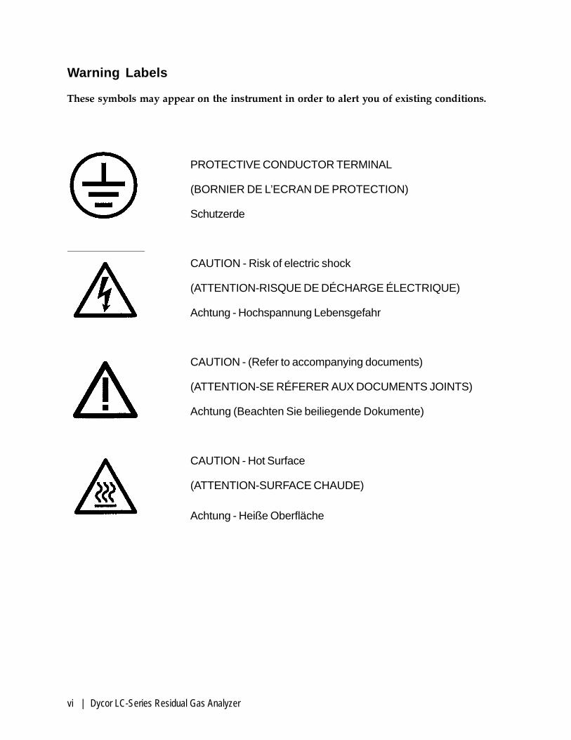
PROTECTIVE CONDUCTOR TERMINAL
(BORNIER DE L’ECRAN DE PROTECTION)
Schutzerde
CAUTION - Risk of electric shock
(ATTENTION-RISQUE DE DÉCHARGE ÉLECTRIQUE)
Achtung - Hochspannung Lebensgefahr
CAUTION - (Refer to accompanying documents)
(ATTENTION-SE RÉFERER AUX DOCUMENTS JOINTS)
Achtung (Beachten Sie beiliegende Dokumente)
CAUTION - Hot Surface
(ATTENTION-SURFACE CHAUDE)
Achtung - Heiße Oberfläche
Warning Labels
These symbols may appear on the instrument in order to alert you of existing conditions.

| vii
Electromagnetic Compatibility (EMC)
Read and follow the recommendations in this section to avoid performance variationsor damage to the internal circuits of this equipment when installed in harsh electricalenvironments.
The various configurations of the LC Series should not produce, or fall victim to, electro-magnetic disturbances as specified in the European Union�s EMC Directive. Strict compli-ance to the EMC Directive requires that certain installation techniques and wiring practicesare used to prevent or minimize erratic behavior of the Analyzer or its electronic neighbors.Below are examples of the techniques and wiring practices to be followed.
In meeting the EMC requirements , the various Analyzer configurations described in thismanual rely heavily on the use of metallic shielded cables used to connect to thecustomer�s equipment and power. Foil and braid shielded I/O and DC power cables arerecommended for use in otherwise unprotected situations. In addition, hard conduit,flexible conduit, and armor around non-shielded wiring also provides excellent control ofradio frequency disturbances. However, use of these shielding techniques is effective onlywhen the shielding element is connected to the equipment chassis/earth ground at bothends of the cable run. This may cause ground loop problems in some cases. These shouldbe treated on a case-by-case basis. Disconnecting one shield ground may not providesufficient protection depending on the electronic environment. Connecting one shieldground via a 0.1 microfarad ceramic capacitor is a technique allowing high frequencyshield bonding while avoiding the AC-ground metal connection. In the case of shieldedcables the drain wire or braid connection must be kept short. A two-inch connectiondistance between the shield�s end and the nearest grounded chassis point, ground bar orterminal is highly recommended. An even greater degree of shield performance can beachieved by using metallic glands for shielded cable entry into metal enclosures. Exposeenough of the braid/foil/drain where it passes through the gland so that the shield materialscan be wrapped backwards onto the cable jacket and captured inside the gland, and tight-ened up against the metal interior.
Inductive loads connected to the low voltage �Alarm Contacts� are not recommended.However, if this becomes a necessity, adhere to proper techniques and wiring practices.Install an appropriate transient voltage suppression device (low voltage MOV, �Transzorb,�or R/C) as close as possible to the inductive device to reduce the generation of transients.Do not run this type of signal wiring along with other I/O or DC in the same shieldedcable. Inductive load wiring must be separated from other circuits in conduit by using anadditional cable shield on the offending cable.
In general, for optimum protection against high frequency transients and other distur-bances, do not allow installation of this Analyzer where its unshieled I/O and DC circuitsare physically mixed with AC mains or any other circuit that could induce transients intothe Analyzer or the overall system. Examples of electrical events and devices known for thegeneration of harmful electromagnetic disturbances include motors, capacitor bank switch-ing, storm related transients, RF welding equipment, static, and walkie-talkies.
!CAUTION

1-viii Western Research Model 4200 Controller
Section title
WARRANTY AND CLAIMS
We warrant that any equipment of our own manufacture or manufactured for us pursuant to our specifica-tions which shall not be, at the time of shipment thereof by or for us, free from defects in material or workman-ship under normal use and service will be repaired or replaced (at our option) by us free of charge, providedthat written notice of such defect is received by us within twelve (12) months from date of shipment ofportable analyzers or within eighteen (18) months from date of shipment or twelve (12) months from date ofinstallation of permanent equipment, whichever period is shorter. All equipment requiring repair or replace-ment under the warranty shall be returned to us at our factory, or at such other location as we may designate,transportation prepaid. Such returned equipment shall be examined by us and if it is found to be defective as aresult of defective materials or workmanship, it shall be repaired or replaced as aforesaid. Our obligation doesnot include the cost of furnishing any labor in connection with the installation of such repaired or replacedequipment or parts thereof, nor does it include the responsibility or cost of transportation. In addition, insteadof repairing or replacing the equipment returned to us as aforesaid, we may, at our option, take back thedefective equipment, and refund in full settlement the purchase price thereof paid by Buyer.
Process photometric analyzers, process moisture analyzers, and sampling systems are warranted to perform theintended measurement, only in the event that the customer has supplied, and AMETEK has accepted, validsample stream composition data, process conditions, and electrical area classification prior to order acknowl-edgment. The photometric light sources are warranted for ninety (90) days from date of shipment. Resaleitems warranty is limited to the transferable portion of the original equipment manufacturer�s warranty toAMETEK. If you are returning equipment from outside the United States, a statement should appear on thedocumentation accompanying the equipment being returned declaring that the goods being returned forrepair are American goods, the name of the firm who purchased the goods, and the shipment date.
The warranty shall not apply to any equipment (or part thereof) which has been tampered with or altered afterleaving our control or which has been replaced by anyone except us, or which has been subject to misuse,neglect, abuse or improper use. Misuse or abuse of the equipment, or any part thereof, shall be construed toinclude, but shall not be limited to, damage by negligence, accident, fire or force of the elements. Improper useor misapplications shall be construed to include improper or inadequate protection against shock, vibration,high or low temperature, overpressure, excess voltage and the like, or operating the equipment with or in acorrosive, explosive or combustible medium, unless the equipment is specifically designed for such service, orexposure to any other service or environment of greater severity than that for which the equipment wasdesigned.
The warranty does not apply to used or secondhand equipment nor extend to anyone other than the originalpurchaser from us.
THIS WARRANTY IS GIVEN AND ACCEPTED IN LIEU OF ALL OTHER WARRANTIES, WHETHEREXPRESS OR IMPLIED, INCLUDING WITHOUT LIMITATION AND WARRANTIES OF FITNESS OR OFMERCHANTABILITY OTHER THAN AS EXPRESSLY SET FORTH HEREIN, AND OF ALL OTHEROBLIGATIONS OR LIABILITIES ON OUR PART. IN NO EVENT SHALL WE BE LIABLE UNDER THISWARRANTY OR ANY OTHER PROVISION OF THIS AGREEMENT FOR ANY ANTICIPATED OR LOSTPROFITS, INCIDENTAL DAMAGES, CONSEQUENTIAL DAMAGES, TIME CHANGES OR ANY OTHERLOSSES INCURRED BY THE ORIGINAL PURCHASER OR ANY THIRD PARTY IN CONNECTION WITHTHE PURCHASE, INSTALLATION, REPAIR OR OPERATION OF EQUIPMENT, OR ANY PART THEREOFCOVERED BY THIS WARRANTY OR OTHERWISE. WE MAKE NO WARRANTY, EXPRESS OR IMPLIED,INCLUDING WITHOUT LIMITATION ANY WARRANTIES OF FITNESS OR OF MERCHANTABILITY, ASTO ANY OTHER MANUFACTURER�S EQUIPMENT, WHETHER SOLD SEPARATELY OR IN CONJUNC-TION WITH EQUIPMENT OF OUR MANUFACTURE. WE DO NOT AUTHORIZE ANY REPRESENTA-TIVE OR OTHER PERSON TO ASSUME FOR US ANY LIABILITY IN CONNECTION WITH EQUIPMENT,OR ANY PART THEREOF, COVERED BY THIS WARRANTY.

Overview | 1-1
OVERVIEW
Dycor LC Series Mass Spectrometer
The Dycor LC Series mass spectrometer is a compact quadrupole massspectrometer primarily used as a residual gas analyzer that offers the mostcost-effective solution to process monitoring needs.
LC Series System
The standard configuration LC Series residual gas analyzer consists of thefollowing components:
• Open ion source quadrupole mass spectrometer in 100 or 200 AMUrange.
• Faraday cup detector or microchannel plate electron multiplier detec-tor.
Options for LC Series System
• Optional integrated System 200 Software that provides:
- variety of operating modes including Analog and Bar, Meter,Annunciator, Tabular, Trend, and Leak Detection,
- auto-tune capabilities,
- Dynamic Data Exchange (DDE) automation for limited control byWindows applications,
- customized displays, and
- single or continuous scan with user-defined interval.
• Dual-pumping system consisting of a turbo pump and oil-vane rotarypump with single-switch power button.
1-2 | Dycor LC Series Residual Gas Analyzer
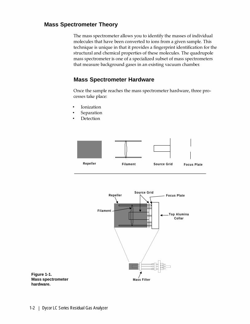
Mass Spectrometer Theory
The mass spectrometer allows you to identify the masses of individualmolecules that have been converted to ions from a given sample. Thistechnique is unique in that it provides a fingerprint identification for thestructural and chemical properties of these molecules. The quadrupolemass spectrometer is one of a specialized subset of mass spectrometersthat measure background gases in an existing vacuum chamber.
Mass Spectrometer Hardware
Once the sample reaches the mass spectrometer hardware, three pro-cesses take place:
• Ionization• Separation• Detection
Repeller Filament Source Grid Focus Plate
. .
. .. .
. .
. .
Filament
RepellerSource Grid
Focus Plate
Top AluminaCollar
Mass Filter
Figure 1-1.Mass spectrometerhardware.

Overview | 1-3
Ionization
During ionization, sample molecules are turned into ions that are thenfocused towards the quadrupole mass filter to be detected. The processoccurs in the source which consists of a filament, filament electron repel-ler, ionizer body, and focusing plate. See Figure 1-1.
The filament produces electrons. As current flows through the filament, itis electrically heated to incandescence and emits free electrons. Once theelectrons are free, they are accelerated towards the ionizer body by thepotential difference between the filament and the ionizer body. As a beamof electrons accelerates towards the ionizer body, the electrons collidewith the vaporized sample in the center of the ion volume and createions.
Once the positive ions are formed, they are extracted from the ion regionand focused towards the quadrupole mass filter by a difference in poten-tial energy.
EI ionization
The energy of the bombarding electrons is much greater than the bondsthat hold the molecule together. When a single electron is removed, apositive ion is created; this is referred to as a molecular ion. When thebombarding electrons cause the molecular bonds to break, fragment ionsform. This fragmentation process is known as electron impact ionization(EI).
Operation of the mass spectrometer depends on maintaining low vacuumpressures. These pressures take into account not only the operationalpressures of the mass spectrometer, but also the pressures of the samplingsystem environments.
Separation
Once the ions reach the quadrupole mass filter, they are filtered accordingto their mass-to-charge (m/z) ratio. Each ion has an identifiable mass. Thequadrupole mass filter is constructed of four electrically-conducting,parallel cylindrical rods. A constant direct current (DC) voltage and analternating radio-frequency (RF) voltage is applied along the length of therods. Through proper electronic tuning, these voltages set the criteria forthe ions that pass through the quadrupole.
As an ion enters the quadrupole mass filter, the RF and DC fields cause itto undergo oscillations. Depending upon the criteria set for motion

1-4 | Dycor LC Series Residual Gas Analyzer
through the quadrupole, an ion either strikes a rod or passes through thequadrupole. Ions meeting the m/z criteria have stable trajectories andemerge from the mass filter assembly (Figure 1-2). Ions with other m/zvalues have unstable trajectories and are neutralized as they strike one ofthe rods.
Ions that successfully pass through the quadrupole are again focusedtowards the detector using an exit aperture which has an applied nega-tive voltage that attracts the positively charged ions.
-
+-
+
+
+
+ ++ +
++
+ DC - DC
IonizationChamber
FocusLens
Quadrupole
ExitLens
Detector
Figure 1-2.Quadrupole massfilter.
Detection
The simplest detection setup consists of a Faraday cup detector. An elec-tron multiplier is used for amplified sensitivity.
A Faraday cup detector is a closed structure except for an opening thatallows the ions to enter. As the positive ions exit the quadrupole massfilter, they strike the detector, creating a current. This current is then sentto the preamplifier for amplification and then to the data system fordisplay.
When an electron multiplier is used, the ions are attracted to the multi-plier because of its negative charge. As the ions strike the multiplier,secondary electrons are emitted. This creates a cascading effect as eachsecondary electron generates more secondary electrons as they movedown the multiplier wall, amplifying the signal by approximately onethousand.

Overview | 1-5
The Dycor system uses a microchannel plate (MCP) electron multiplier. Itconsists of an array of millions of small glass capillaries fused together inthe shape of a disk. The inside wall of each channel has a resistive, electri-cally semiconductive layer, forming independent electron multipliers. Asthe ions are approaching the MCP, a positive electrical gradient pulls theelectrons into the MCP. As they cascade down and strike the channelwalls, they generate secondary electrons. The Dycor MCP has the advan-tage in that it is air stable and is especially beneficial for detection of low-level species.

1-6 | Dycor LC Series Residual Gas Analyzer
This page intentionally left blank.

Specifications | 2-1
LC-SERIES SPECIFICATIONS
Mass Range:
1 - 100 AMU standard; 1-200 AMU optional
Operating Pressure Range:
10 -4 Torr to ultrahigh vacuum
Minimum Detectable Partial Pressure:
5 x 10 -12 Torr (5 x 10 -14 Torr for electron multiplier units)
Resolution:
Adjustable to constant peak width (0.5 AMU at 10% height)
Emission Current:
0.1 to 10 mA; 50 mA to degas
Electron Energy:
30 to 150 volts to operate; 200 volts to degas

2-2 | Dycor LC Series Residual Gas Analyzer
Ion Energy:
1 to 10 volts
Source Sensitivity (Faraday Cup):
2 x 10 -4 amps per Torr at detector (measured with nitrogen at mass 28with peak width = 0.5 at 10% height and 1 x 10 -3 amps emission current)
Power Requirements:
110 VAC 1 amp or 220 VAC 0.5 amp
Stability:
Mass stability: ± 0.1 AMU after 30-minute warm-up;
Peak Height: ± 2% after 30-minute warm-up.
RS-232 Serial Communications Interface:
Isolated; baud rate 38,4009-pin, female D-connector
Accessory Output
2 Digital TTL
1 Analog 0-10 volts
15-pin, female D-connector
Physical Dimensions:
Weight 14 lb. (6.3 kg)Width 16� (40.6 cm)Length15� (38.1 cm)Height 3.5� (8.9 cm)

Installation | 3-1
INSTALLATION
This chapter contains information on the installation and initial operationof the LC Series system including the following:
• Mechanical installation
• Communications setup

3-2 | Dycor LC Series Residual Gas Analyzer
Mechanical Installation
If you are not familiar with high vacuum systems and procedures andwith handling the quadrupole head in a manner that will preventcontamination, please refer to Chapter 6 of this manual for properhandling procedures before continuing.
The LC-Series source is shipped wrapped in a protective covering. Checkall parts to ensure that nothing has been damaged. If you discover dam-age, report it to the factory immediately.
1. Visually check the filament for integrity.
2. Install the sensor assembly into vacuum system.
3. Connect the LC Series electronics to the sensor.
4. Connect the LC Series electronics to AC power (120/230 VAC).
Check Sensor Filament.
1. To check the filament to ensure that it has not been damaged duringshipment, visually inspect the filament to make sure that it is notbroken.
2. Using a standard ohm meter, check the continuity of the filament tomake sure that an open circuit does not exist between Pins 2 and 6 ofthe vacuum feedthrough pins (see Figure 3-1). A resistance of lessthan 1 ohm is required.
3. Check the resistance between Pins 2 or 6 to all other pins. They shouldall show an open resistance to operate properly.
!CAUTION
Figure 3-1.Keyway from outsidethe sensor flange.
1
2
8
9
7
6
54
3
Keyway
Filament
Repeller Grid
Focus Plate
Filament
Source Plate

Installation | 3-3
Connect Sensor to the Vacuum System
The sensor is contained within a stainless steel nipple (see Figure 3-2). Thenipple ends with a 2 3/4” Conflat flange that will mate to your vacuumchamber. A copper gasket is included to provide a high integrity metal-to-metal seal between the source and your chamber. When inserting thesource into your vacuum chamber, make sure that the repeller grid doesnot short against the inside of the chamber walls.
1. Using a new copper gasket between the flange and the source, installthe source into the nipple so that the repeller clears the chamber walls(Figure 3-2). A new copper gasket must be used each time the sourceis removed and reinstalled.
2. Align the source at the 7 o’clock position on the keyway.
There is a keyway on the feedthrough side of the source (Figure 3-1).This keyway ensures proper pin orientation when the electrometer isinstalled. When mounting the source, we recommend that the key-way be in the 7 o’clock position. This position will allow the electrom-eter cable to hang straight down once it is installed, minimizing strainon the cable.
3. Bolt the source flange in place using the screws and washer provided.Tighten in a star pattern to ensure a good seal.
Electrometer
Source
FeedthroughPins
Nipple
StainlessSteel Bolts
2 3/4”
Conflat Flange
Copper Gask
Repeller Grid
Figure 3-2.Sensor assembly.
3-4 | Dycor LC Series Residual Gas Analyzer
!CAUTION
Connecting the Source to the Electronics
Power to the LC Series must be off.
The source was already checked at the factory where the filament integ-rity was validated.
• Visually align the slot on the electrometer to the keyway on themiddle feedthrough of the source assembly (Figure 3-3). This ensuresthat the electrometer is properly connected to the source. A looseconnection can cause a filament trip message to appear on the displayscreen.
The electrometer can be disconnected and then reconnected to the sourcesimply by pulling it from the source and pushing it back on. Do not twistthe electrometer on the analyzer, this will damage the vacuumfeedthroughs.
The electrometer must be disconnected from the source during bake-out so as not to damage the electronics.
Bake-out of the source must be conducted under a vacuum to minimizeoxidation of the analyzer head components. This is normally done onlyfor low pressure work. When baking near the maximum temperature(350° C), limit the rate of change to 5 °C per minute. This protects theanalyzer during repeated bakes.
Connecting the Electrometer to the Power Supply
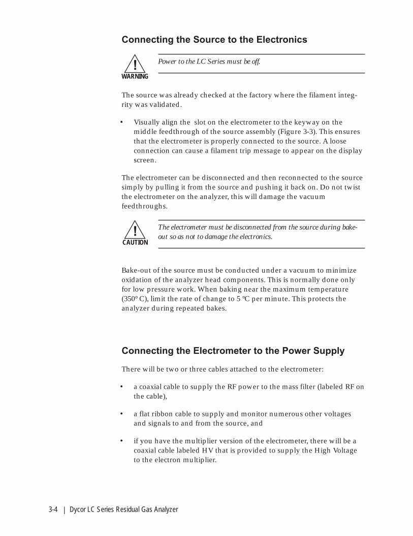
There will be two or three cables attached to the electrometer:
• a coaxial cable to supply the RF power to the mass filter (labeled RF onthe cable),
• a flat ribbon cable to supply and monitor numerous other voltagesand signals to and from the source, and
• if you have the multiplier version of the electrometer, there will be acoaxial cable labeled HV that is provided to supply the High Voltageto the electron multiplier.
!WARNING

Installation | 3-5
Follow these steps to connect the electrometer to the power supply(Figure 3-3):
1. Connect the cable marked RF to the connector labeled RF on the rearof the power supply. Line up the slot on the RF cable with the key onthe top of the RF connection on the power supply and press the cablein. Turn it until it locks.
2. Connect the flat ribbon cable to the 37-pin female connector on thepower supply (marked “analyzer”). This connector is keyed to pre-vent an incorrect cable connection.
3. If you have the electron multiplier electrometer, connect the cablelabeled HV (high voltage) to the connector labeled HV on the powersupply.
FRONT VIEWElectrometer
HV Coaxial Cable
used only with
multiplier option
H.V. RS-485
RS-485
POWER
ACCESSORY ANALYZER
R.F.
Fla
t R
ibb
on
Cab
le
RF Coaxial Cable
POWER SUPPLY(Rear View)
Figure 3-3.LC connections fromrear of power supplyto electrometer.
3-6 | Dycor LC Series Residual Gas Analyzer
!CAUTION
Switching Between 110 and 220 Volts AC Line
The power requirements for the LC Series power supply are 110 or 220VAC at 200 watts 50/60 Hz. To switch from 110 to 220 volts, it will benecessary to do the following:
1. Turn off the power switch to the LC Series power supply.
2. Remove the power cord from the LC power supply.
3. Slide the plastic door on the power connector to the left to expose thefuse.
4. Using a pair of pliers, remove the small circuit board directly belowthe fuse.
5. Turn the card 180° and install it with the side labeled “240” visible. The240 should appear legible to you as you are pushing it into place andshould NOT appear upside down.
6. Slide the door to the left and install a 220-volt power cord.
Connect the LC Power Supply to the AC Line Power
Be sure that the power switch on the power supply is turned off.
1. Plug the power cord that is provided with the power supply into thepower outlet located on the rear of the power supply.
2. Plug the opposite end of this power cord into the appropriate ACpower outlet.
Since heat is given off during normal operation, you must take care not toobstruct the airflow through the heat sink on the rear panel of the powersupply. If the power supply is to be rack-mounted, it should not be placedin a closed rack without air circulation.

Installation | 3-7
Connecting the LC Series to a PC
The LC Series can be connected to your PC either through the optionalDycor System 200 software, or by using the serial communications proto-col provided in Chapter 4.
RS-232 port connection
To connect your analyzer to your PC you will need a serial cable with a 9-pin DB-9 male connector on one end of the cable and a DB-9 femaleconnector on the other end.
• Connect the male connector end of the cable to the front RS-232 porton the LC Series.
• Connect the female connector end of the cable to the RS-232 port onyour PC.
With an RS-232 connection, the distance limit between the PC and the LCSeries power supply is 50 feet.

3-8 | Dycor LC Series Residual Gas Analyzer
RS-232 Communication Cables
The maximum cable length for standard RS-232 cable is 50 feet. You canuse low capacitance RS-232 cable for up to 200 feet.
LC Series DB-9M
Pin 2 Transmit
Pin 3 Receive
Pin 5 Ground
LC Series DB-9M
Pin 2 Transmit
Pin 3 Receive
Pin 5 Ground
Computer DB-9F
Pin 2 Receive
Pin 3 Transmit
Pin 5 Ground (required)
Computer DB-25F
Pin 3 Receive
Pin 2 Transmit
Pin 7 Ground (required)

Installation | 3-9
Accessory Output
The LC has two digital outputs and one analog output available througha DB-15F connector located on the back panel of the LC analyzer.
The digital outputs are TTL signals (0V or 5V)
Pin 5 Digital Output 0 “Dig Out 0” in the System 200
Pin 6 Digital Output 1 “Dig Out 1” in the System 200
Pin 13 Digital Common
The analog output has a 12-bit resolution with a range of 1 to 10V.
Pin 4 Analog Output “Ana Out 0” in the System 200
Pin 14 Analog Common

3-10 | Dycor LC Series Residual Gas Analyzer
This page intentionally left blank.

Serial Communications | 4-1
SERIAL COMMUNICATIONS
Communications Protocol
Host Communications
The LC has one RS-232 serial port. The baud rate is 38400.
Protocol
@AAFFddddCC[CR] CommandA[CR] AcknowledgeAddddCC[CR] Acknowledge with dataNEE[CR] Error with code
Char Function@ Command startAA Two character ASCII decimal node address (Ignored)FF Two character ASCII hex function codedddd Up to 240 characters of ASCII dataCC Two character ASCII hex checksum; ignored if set to �??�A AcknowledgeN ErrorEE Error code[CR] End of message, hex 0D
The node address is ignored; the LC will respond to any address.
The checksum is a modulo 256 summation of the characters making upthe function code and data. For example, to turn on the filament:
@0104195 [CR] 95h = 30h + 34h + 31h
If, when sending a command, the inter-character delay exceeds twoseconds, the LC will time-out. The command will be discarded and theLC will start waiting for the next command. Because of the time-outrequirement, you need to use a program to send commands.

4-2 | Dycor LC Series Residual Gas Analyzer
Function: 00 Status
This is the only command that will work before you log in.
If no parameter supplied, returns the current LC Series status as a two-digit hex value.
Bit 0: 0x01 Protect pressure exceeded
Bit 1: 0x02 Filament open
Bit 2: 0x04 Filament half open
Bit 3: 0x08 Filament trip
Bit 4: 0x10 RF failure
Bit 5: 0x20 Power supply communications error
Bit 6: 0x40 Communicating through the RS-232 port
Bit 7: 0x80 Multiplier option present
If sending a subfunction code in the first byte of the data block:
Subfunction: R ResetLogs in this port, stops scanning, resets system, clears error anddisplay.
Subfunction: L Log InRequests log-in to the LC Series. Stops scanning, resets system, clearserrors and display.
Subfunction: O Log OutLog-out from the LC Series. Stops scanning, turns off filament, multi-plier, and degas mode.
Subfunction: I InformationGet information string.
Returns�Dycor LC N.n� Where N.n is the firmware version, e.g. 1.0.
Subfunction: A Repeat Last ACKRepeat the last acknowledge message sent. if an ACK message isreceived with errors, use this to retransmit it.
ReturnsA copy of the last ACK message sent.

Serial Communications | 4-3
Function: 01 Auto RF Tune
Starts the automatic RF tune procedure. Not allowed when scanning.
Parameters
1 (Starts the auto tune RF)
Returns
If no parameter supplied, returns �1� if auto RF tune is still in progress. �0�if done.
Function: 02 Tune Data Read-only
Get the latest tune data.
Returns
A string in the format �3.52E-08 1.0E-03 7.216 2.1 3.0� The values are totalpressure, emission current, RF tune, filament voltage, and filament cur-rent.
Function: 03 Scan
Start or stop scanning. Clears the data buffer when started. Sets thenumber of scans.
Parameters
scans � Zero stops scanning. A-1 scans forever. Range is -1, or 0 to 32767.
Returns
If no parameter supplied, returns the number of scans remaining.

4-4 | Dycor LC Series Residual Gas Analyzer
Function: 04 Filament
Turn the filament on or off. If scanning, does not take effect until the nextscan.
Parameters
1 (Turn on)2 (Turn off)
Returns
If no parameter supplied, returns the current value.
Function: 05 Multiplier
Turns the multiplier on or off. If scanning, does not take effect until thenext scan.
Parameters
1 (Turn on)2 (Turn off)
Returns
If no parameter supplied, returns current value. If this is not a multiplierpower supply, then always return �-1.�

Serial Communications | 4-5
Function: 06 Channel Parameters
Sets the channel type and parameters. No changes are allowed if scan-ning.
Parameters
chan A low high dwell samples [gain] [offset] [offset2] (Analog mode)chan B low high dwell [gain] [offset] [offset2] (Bar mode)chan T mass dwell [gain] [offset] [offset2] (Tabular mode)chan P [gain] [offset] [offset2] (Pressure-total pres-
sure)chan N (Tune mode)chan D (Disable)C (Disables all channels)chan (Return current chan-
nel parameters)
chan is the channel number. Range: 0 to 31.low is the low mass. Range: 1 to 219.high is the high mass. Range: 2 to 220.
dwell is the sample dwell time. Range: 3, 4, 5, 10, 15, 30,60, 120, 250, 500, 1000,2000, 4000, 8000, 16000
samples is the samples per AMU. Range: 4 to 15.gain is an optional parameter for sample gain. Defaults to 1.0 if not set.offset is an optional parameter for sample offset. Defaults to 0 if not set.offset2 is an optional parameter for sample offset. Defaults to 0 if not set.
The data values are modified by the following formula:
NEW_VALUE = ((VALUE + offset) x gain) + offset2
Returns
If just chan is supplied, then one of the above strings is returned (includ-ing gain, offset, offset2).

4-6 | Dycor LC Series Residual Gas Analyzer
Function: 07 Scan Interval
Sets the number of seconds between scans.
Parameters
interval - Range: 0 to 32767.
Returns
If no parameter supplied, returns current value.
Function: 08 Analog Output
Sets the Power Supply analog output voltage. If scanning, does not takeeffect until the next scan.
Parameters
value �Range: 0 to 4095.
Returns
If no parameter supplied, returns current value.
Function: 09 Digital Output
Sets one or both of the Power Supply the digital outputs. If scanning, doesnot take effect until the next scan.
Parameters
0 (All off)1 (#1 on, #2 off)2 (#1 off, #2 on)3 (all on)10 (#1 off, #2 don�t change)11 (#1 on, #2 don�t change)

Serial Communications | 4-7
20 (#1 don�t change, #2 off)22 (#1 don�t change, #2 on)
Returns
If no parameter supplied, returns current value: 0, 1, 2, or 3.
Function: 0C Calibration Parameters
Sets the calibration parameters for the head.
Parameters
Freq LoMass HiMass LoPos HiPos LoRes HiRes LoSen HiSen Cal Tsens Mult
Freq PLL frequency in MHz. Range: 2.000E+06 to 3.000E+06.LoMass Low calibration mass. Range: 1 to 100HiMass High calibration mass. Range: 1 to 200LoPos Low position. Range: -10.00 to 10.00.HiPos Low position. Range: -10.00 to 10.00.LoRes Low resolution. Range: 50 to 4100.HiRes High resolution. Range: 50 to 4100.LoSen Low sensitivity. Range: 3.00 to 10.00.HiSen Low sensitivity. Range: 3.00 to 10.00.Cal Amplifier calibration. Range: 1.0E-10 to 1.0E10.TSens Total sensitivity. Range: 0.1 to 999.9.Mult Multiplier voltage. Range: 0 to -1300.
Returns
If no parameter supplied, then the calibration parameter string is re-turned. If not a multiplier power supply, Mult always returns zero.

4-8 | Dycor LC Series Residual Gas Analyzer
Function: 0D Ionizer Parameters
Sets the ionizer parameters for the head.
Parameters
Emis ElEnergy Focus Repeller
Emis Emission current. Range: 1.0E-04 to 1.0E-02.
ElEnergy Electron energy. Range: -150.0 to -30.0
Focus Focus voltage. Range: -200.0 to +10.0.
Repeller Repeller voltage. Range: -170.0 to -30.0.
Returns
If no parameter supplied, then the ionizer parameter string is returned. Ifmultiplier power supply, Repeller always returns zero.
Function: 0E Autozero
Turn the autozero option on or off. When turned on, the scanning timewill double. For each data point, two readings are taken. One normal, andone with the mass filter blocking all ions.
Parameters
1 (Turn on)0 (Turn off)
Returns
If no parameter supplied, returns current value.

Serial Communications | 4-9
Function: 0F Set Time
Set the real time clock. Note that the time and date are not maintainedwhen powered off.
Parameters
month/day/year hour:minute:second
month 1 to 12.day 1 to 31.year four digit year, e.g. 1998hour 00 to 23. This must be in 24-hour format.minute 00 to 59.second 00 to 59.
Returns
If no parameter supplied, returns current date and time in the format:
month/day/year hour:minute:second.hundredths

4-10 | Dycor LC Series Residual Gas Analyzer
Function: 10 Get Data
Get scan data for one channel for each call.
ParametersC Clear scan data.T Return time of scan before each scan.P Return total pressure, if available, before each scan.N Set maximum number of data points to return � 1 to 16.
ReturnsEcode (Error status)Tpressure (Optional total pressure)
S[date time] channel count data1 data2 data3 data4 ... dataN (Start of scandata)
Cchannel count data1 data2 data3 data4 ... dataN (Continued scan data)on same channel)
channel count data1 data2 data3 data4 ... dataN (Scan data)
O (Scan is off - no data)No data returned indicates that scanning is on, but no data is ready.
If S is the first returned character, it indicates the start of a set of scan data. IfS is returned, it is optionally followed by the date and time of the start of thescan. If C is the first returned character, it means that additional scan datafor the channel is being returned.
code � Two digit hex error code - see STATUS command.
date � Format: �06/10/94�.
time � Format: �15:42:23.44�.
channel � Channel number from 0 to 31.
count � Number of data values returned from 1 to 16. Tabular and TotalPressure mode channels always return one data value. Tune mode chan-nels return five values.
data � Scan data in the format: �1.23E-08� except for tune mode. If tunemode, the values are total pressure, emission current, RF tune, filamentvoltage, and filament current.
Serial Communications | 4-11
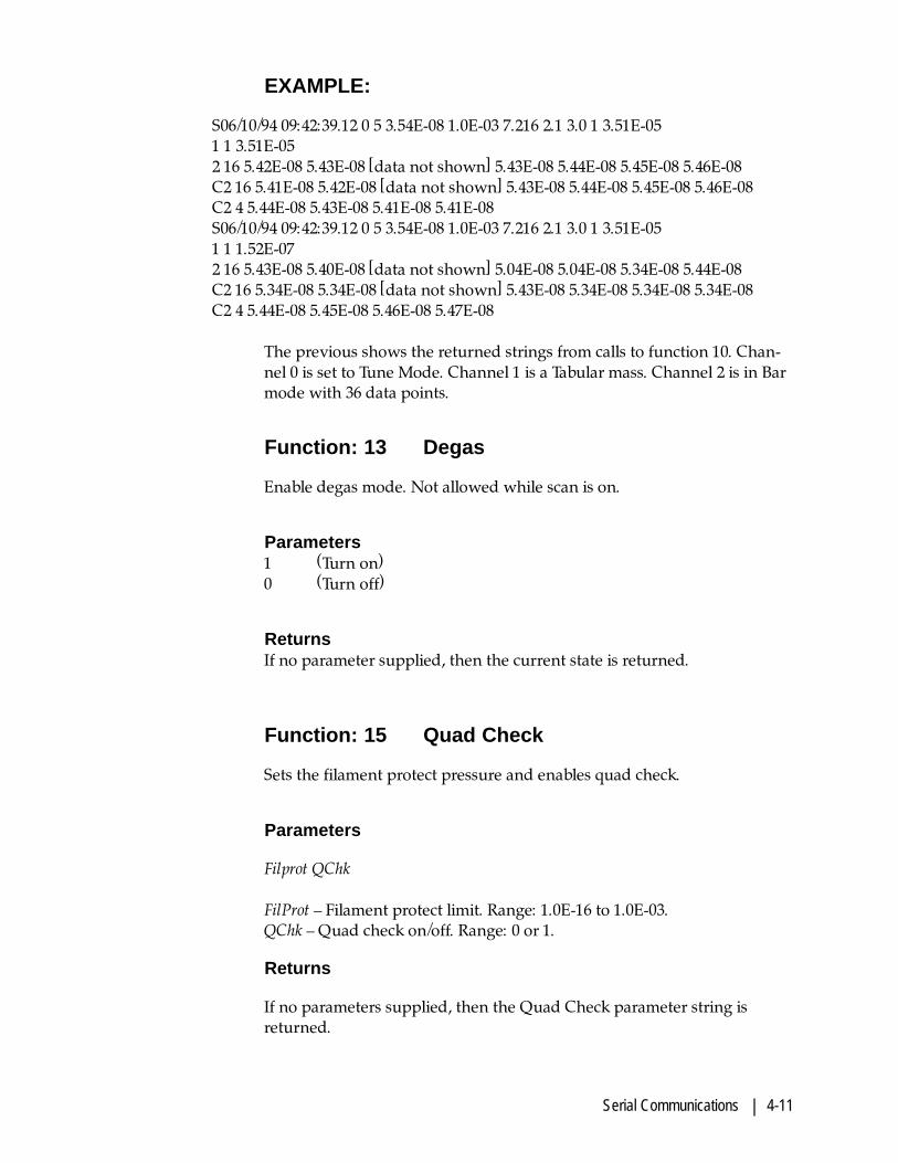
EXAMPLE:
S06/10/94 09:42:39.12 0 5 3.54E-08 1.0E-03 7.216 2.1 3.0 1 3.51E-051 1 3.51E-052 16 5.42E-08 5.43E-08 [data not shown] 5.43E-08 5.44E-08 5.45E-08 5.46E-08C2 16 5.41E-08 5.42E-08 [data not shown] 5.43E-08 5.44E-08 5.45E-08 5.46E-08C2 4 5.44E-08 5.43E-08 5.41E-08 5.41E-08S06/10/94 09:42:39.12 0 5 3.54E-08 1.0E-03 7.216 2.1 3.0 1 3.51E-051 1 1.52E-072 16 5.43E-08 5.40E-08 [data not shown] 5.04E-08 5.04E-08 5.34E-08 5.44E-08C2 16 5.34E-08 5.34E-08 [data not shown] 5.43E-08 5.34E-08 5.34E-08 5.34E-08C2 4 5.44E-08 5.45E-08 5.46E-08 5.47E-08
The previous shows the returned strings from calls to function 10. Chan-nel 0 is set to Tune Mode. Channel 1 is a Tabular mass. Channel 2 is in Barmode with 36 data points.
Function: 13 Degas
Enable degas mode. Not allowed while scan is on.
Parameters1 (Turn on)0 (Turn off)
ReturnsIf no parameter supplied, then the current state is returned.
Function: 15 Quad Check
Sets the filament protect pressure and enables quad check.
Parameters
Filprot QChk
FilProt � Filament protect limit. Range: 1.0E-16 to 1.0E-03.QChk � Quad check on/off. Range: 0 or 1.
Returns
If no parameters supplied, then the Quad Check parameter string isreturned.

4-12 | Dycor LC Series Residual Gas Analyzer
Error Codes
N01 Bad Command
The command sent is not recognized.
N02 Checksum
The calculated checksum didn�t match the checksum sent.
N05 Write-Only
The command is write-only. Can�t return a query.
N06 Out of Range
The parameter sent is out of range.
N07 Memory
The command tried to allocate memory and failed.
N08 Reset
The LC Series has been reset. You must send a 00R or 00L command.
N10 Scan
The command sent is not allowed while scanning.

Sampling Systems | 5-1
VACUUM AND PRESSURE REDUCTION SYSTEMS
This chapter describes the pumping and pressure reduction systemsavailable as options on the Dycor analyzers. They include the following:
• Pumping Station - See Figure 5-1.
• Pressure Reduction System (M240) - See Figure 5-2.
• Atmospheric Pressure Sampling System (M250) - See Figure 5-4.

5-2 | Dycor LC Series Residual Gas Analyzer
Pumping System
Installation
1. Use a 7/16" wrench to loosen the four nuts that secure the roughingpump during shipment. The springs that the roughing pump rests onshould not be compressed but rather fully decompressed (withinlimits) to allow them to act as vibration dampers.
2. The rotary vane roughing pump is shipped with oil. The oil levelshould be about half-way up the oil sight glass when the pump issitting on a level surface. The exhaust port is plugged during ship-ment to reduce the possibility of oil spilling. Remove this plug.
3. Make sure that all valves are closed on the pressure reduction system.You can now turn on the pumping system by pressing the pumppower button on the pumping station controller.
4. If the system is sealed, the rotational speed indicator will indicate fullspeed by moving fully to the right within a few minutes. If the systemis not sealed, the turbomolecular pump will never reach full speedand may turn itself off due to thermal overload. If this happens, letthe system cool and then try to locate the coarse leak. Since the sys-tems are tested extensively at the factory, double check any systemconnections made by the user. When the system is restarted after athermal shutdown, the STANDBY button must be pressed at the sametime as the START button. Press the STANDBY button to allow thepump to achieve full speed.
5. When the turn gets to full rotational speed, the analyzer is ready to beused. The analyzer can now be used for further leak checking in thehigh vacuum realm.
6. When you want to vent your system, turn off the source electronicsand push the pump power button again. The system will automati-cally vent.
Allow the filament to cool for several minutes before venting thechamber.
Although this is all you need to know to start operating your system, weadvise that you read the manual that comes with the pumping system formore details and maintenance instructions.
!NOTE

Sampling Systems | 5-3
Figure 5-1.Pumping station withrotary vane (oil) pumpand diaphragm (dry)pump.

5-4 | Dycor LC Series Residual Gas Analyzer
Pressure Reduction System
The M240 pressure reduction system is a vacuum manifold that housesthe Dycor source. It is used to maintain the required low operating pres-sure of the source when sampling from higher pressure (See Figure 5-2).
The M240 pressure reduction system is used in conjunction with theturbomolecular pumping station. This pumping station is intended to beattached to the 4 ½� Conflat flange.
The source is placed on the 2 ¾� Conflat flange opposite the handle of thehigh conductance valve. The 2 ¾� Conflat flange located at the side of thisvalve can be used for attachment to the vacuum system to be sampledand which will be designated as the test chamber.
When open, the high conductance valve allows the source to sampledirectly from the test chamber. This should be done only when the testchamber is pumped down below 10E-5 Torr. Since the vacuum capabilityof the pumping station is better than 10E-8 Torr, the residual gases de-tected will, for the most part, originate from the test chamber. This maynot be the case if measurements are taken when the base pressure withinthe test chamber is below 10E-8 Torr. In this case, a source connecteddirectly to the test chamber should be used.
When the pressure in the test chamber is above 10E-5 Torr, the high con-ductance valve should be tightly closed. This valve is closed by firstrotating the center hex nut fully counter-clockwise and then manuallytightening the large knob clockwise. This should place the poppet over
Figure 5-2.M240 pressurereduction system.

Sampling Systems | 5-5
the valve seat but will not seal the valve. Use a 7/8" torque wrench totighten the 7/8" (22 mm) hex nut (turn clockwise). The center nut shouldbe tightened to no more than 45 ft-lb. Use the least amount of torquerequired to achieve a leak-tight seal (a torque of 20 ft-lb. (27 Nt-m) or lessshould seal the valve). The quality of the seal can be determined by usingthe source as a leak checking device.
The M240 pressure reduction system comes with a molecular leak andvalve which bypasses the high conductance valve seal. The molecularleak is located on the gasket of the high pressure side of the two VCRfittings used to mount the bypass. The VCR seal is made by placing thegasket between the sealing glands and turning the female nut ¼ turnbeyond finger tight. The M240 system comes with the seals to one bypassarm already made.
Fittings for a second bypass arm (M142) are blanked off. If a secondmolecular leak is desired the customer must purchase an additionalbypass arm and seal the bypass as described above. Alternatively, thefittings for the second molecular leak can be used to attach an optionalvalve and capillary (M144) to be used for atmospheric sampling or asanother aperture.
The molecular leak bypass is used to reduce the pressure found in the testchamber to a pressure compatible with the operation of the source. Thehigh conductance valve must be closed whenever the test chamberpressure is greater than 10E-5 Torr. The bakeable valve on the bypass armshould be opened slowly since a volume of higher pressure gas is ex-pected to be found between the valve and the molecular leak. Once thisvolume has been evacuated, the pressure in the test chamber, the diam-eter of the molecular leak, and the pumping system speed will determinethe pressure at the source. If this pressure is still too high (above 10E-5
Torr) or if the pressure is too low for your desired sensitivity, then asecond molecular leak can be used. The valve in the first bypass can thenbe closed and the molecular leak in the second bypass can be activated byopening the second bypass valve.
The pressure reduction ratios for different molecular leak aperture diam-eters are given for the pumping station in Figure 5-3.

5-6 | Dycor LC Series Residual Gas Analyzer
Although previously used molecular leaks and gaskets have sealed uponreuse, in order to maintain the reliability of the original seal, we recom-mend that new gaskets and molecular leaks be used whenever the bypassarm is resealed after a molecular leak has been changed.
The bypass valves can be used to turn off the molecular leak at any time.This is especially useful when you are concerned that the measurement isinfluenced by the residual gas within the pumping system. The molecularleak can be turned off and a background spectrum can be taken. Thisbackground can then be subtracted from the spectrum taken with themolecular leak open to the system.
You can reduce the background spectrum of the M240, the pumpingsystem and that of the analyzer itself by baking the manifold. This can bedone using either a heating tape or the M107 heating jacket. The elec-trometer must be removed during bakeout. The system will withstand amaximum temperature of 350 °C, but baking for a few hours at a tempera-ture between 100 °C to 200 °C is usually satisfactory. The necessity forbaking and the time and temperature required will vary from applicationto application.
Figure 5-3.Pressure reductionratio for molecularleak aperturediameters.
Aperture Size Pressure Ratio Max. Sample
(Microns) Chamber Pressure (Torr)
2 6.0 x 10⁷ 600
5 1.0 x 10⁷ 100
10 2.5 x 10⁶ 25
20 6.0 x 10⁵ 6
50 1.0 x 10⁵ 1
100 2.5 x 10⁴ .25
200 6.0 x 10³ 6.0 x 10⁻²
500 1.0 x 10³ 1.0 x 10⁻²
1000 2.5 x 10² 2.5 x 10⁻³
No Aperture 70 7.0 x 10⁻⁴

Sampling Systems | 5-7
Rack-Mount and Other Applications (M240)
The M240 pressure reduction system is attached directly to the inlet of theturbomolecular pump using a rotatable 4 ½� Conflat-type flange. Theconfiguration of the turbomolecular pump with respect to the pumpingsystem rack depends upon the user application. If the chamber to besampled is small and supportable from the M240 sampling port, then theturbomolecular pump can remain in the rack and the rack can be placedon a bench or table top. If the test chamber is large and its sampling porthigh above ground level, the turbomolecular pump should be removedfrom the vacuum system rack by removing the four mounting screws atthe bottom of the unit. The M240 and turbomolecular pump can then besupported from the sampling port. In this case, replace the short stainlessline that is used to rough pump the turbomolecular pump by the plasticvacuum hose supplied with the pumping system.
The turbomolecular pump comes with power leads and a vacuum hoselong enough to operate the turbomolecular pump at a distance of up tonine feet from the pumping station. The turbomolecular pump andmanifold are light enough to be supported by a port that calls for a 2 ¾�flange. The turbopump can be operated at any angle with respect to thevertical between straight down and horizontal. The pump should not berun in an upside-down position.
The roughing hose should be kept as short as possible so carefully mea-sure the length required and cut the hose to that length. Use the hoseclamps to place KF fittings to the ends of the hose. Then attach the KFfittings to the turbopump and the roughing pump.
Three electrical cables must lead from the turbomolecular pump to thevacuum system rack. These are the turbo power cord , the heater cordand the vent valve cord. It may be convenient to bundle these wirestogether.
The rack can be placed on the floor or other convenient location.!NOTE

5-8 | Dycor LC Series Residual Gas Analyzer
Atmospheric Pressure Sampling System
The M250 atmospheric sampling system (Figure 5-4) is used as an atmo-spheric pressure gas inlet system. It requires a pump capable of about 50 l/s pumping speed such as the Dycor turbomolecular pumping station. TheM250 is used to house the Dycor source in the required high vacuumenvironment.
Figure 5-4.M250 pressuresampling system.
The pumping station is attached to the M250 via a 4 ½� Conflat-typeflange using the copper gasket supplied.
The gas inlet is a 1-meter long length of fused silica capillary with aninside diameter of 50 microns (10 microns inside diameter also available).The low conductance of the capillary is used to decrease the sample gaspressure from atmospheric to about E-6 Torr at the quadrupole sensor.
The advantages of the capillary are that gas travels through the system incontinuous laminar flow. The local gas composition along the capillarypath retains the time signature of what happened at the sampling end ofthe capillary. If the capillary becomes clogged, it is only necessary to breakoff a short section from the sampling end of the capillary to be back inoperation.
A bakeable valve is found at the end of the capillary which can be used toturn off the flow of gas to the high vacuum region. The valve can beclosed to look at the system background spectrum. The entire system isbakeable to 350 °C when the electrometer is removed from the system.When looking at gases that will condense at room temperature, the inletcan be heated to a temperature of about 120 °C. This can be done bywrapping the inlet in heating tape or an M107 heating jacket taking carenot to overheat the electrometer.
Sampling Systems | 5-9
The capillary is sealed to the sampling system using a graphitized vespelferrule. This ferrule must be tightened to avoid air leaks. The cured softsilicon rubber, found in the black stick-on bumpers, makes an ideal stop-per for the fused silica capillary. Just push the sampling end of the capil-lary into the rubber to make the seal. If there were no previous air leaks inthe system, the capillary can be sealed in this way, the capillary valve isopened, and the source can be used to leak test the ferrule seal. If there isa leak, the peaks at masses 28 and 32 will have the characteristic 4-to-1peak height ratio of nitrogen and oxygen peaks in air.
The capillary is essentially a long narrow tube. Assuming the low pressureend of the capillary will be at a pressure of E-5 Torr or less, that you aresampling from atmospheric pressure, and that you have a linear pressuredrop along the length of the capillary, the pressure within most of thecapillary is a significant fraction of atmospheric pressure. The conditionfor laminar flow is that the mean free path of the molecules in the flow bemuch smaller than the diameter of the flow. Since the mean free path atatmospheric pressure is about 1.0E-6 cm and the capillary diameter is 5-3
cm, laminar flow is expected along the entire length of the capillaryexcept at perhaps the last mm of the capillary.
The Poseuille equation given below should give a good approximation ofthe conductance of the capillary given:
• Gas viscosity of 180 x E-6 poise
• Ñ P is the pressure drop across the capillary in Torr
• P is the mean pressure in the capillary in Torr
• d is the capillary diameter in cm
• L is the capillary length in cm
• Q is the conductance in Torr l/s
Q = ( 182 ∇ P P d4
L )Equating the pumping speed for a capillary of 50 microns ID and a lengthof 1 meter to the pressure at the ionizer times the system pumping speed(at this point) of 22 l/s, this gives a pressure at the ionizer of E-6 Torr.

5-10 | Dycor LC Series Residual Gas Analyzer
This page intentionally left blank.

Maintenance & Troubleshooting | 6-1
MAINTENANCE AND TROUBLESHOOTING
This section includes information on:
• maintaining the quadrupole head,
• changing the filament,
• replacing the source
• cleaning the source
• reassembling the source
• cleaning the electron detector.
• troubleshooting the LC Series
The rest of the analyzer should require no routine maintenance duringnormal use.
Disconnect all power from the analyzer before starting these proce-dures.
Touching any part of the quadrupole head source or mass filter withyour fingers will leave dirt and oil on the parts resulting in contami-nation of the quadrupole head. Use clean plastic/latex gloves whenhandling components.
!WARNING
!CAUTION
6-2 | Dycor LC Series Residual Gas Analyzer
Quadrupole Head Maintenance
� The quadrupole head requires periodic maintenance. This mainte-nance can be performed by anyone familiar with vacuum systemstandard practices.
� The entire head can be disassembled with the exception of the massfilter subassembly. Most parts can be replaced if necessary.
� As the analyzer head is used, deposits will form on the source partsand on the mass filter. The lifetime of the source parts varies withapplication, exposure time, and vacuum pressure.
Do not place the mass filter in an ultrasonic cleaner. The filter partscan become loose during ultrasonic cleaning. This will significantlydegrade analyzer performance. A loosened mass filter must be re-placed.
Filaments
Open Source
The Dycor open source contains a dual-wire filament so the analyzer cancontinue to function if one side of the filament burns out. The replace-ment filament comes in a protective container and can easily be replacedin the field.
Equipment required to replace a filament
� needle nose pliers,
� 1/16� hex wrench (supplied by AMETEK/Dycor),
� filament assembly kit (supplied by AMETEK/Dycor),
� latex gloves - powder-free (optional).
Handling the filament by the shorting tabs on the filament plate willensure against contamination through handling since these tabs willeventually be discarded.
!CAUTION
!NOTE

Maintenance & Troubleshooting | 6-3
Removing the LC electrometer from the quadrupole head
• Disconnect all cables of the electrometer from the power supply toavoid electrical shock.
• After powering down the LC Series, gently pull straight back on theLC source, without twisting, until it is free of the electrometer.
Replacing the filament
1. Remove the six (6) ¼-28 bolts that hold the nipple to the sourcefeedthrough (Figure 6-1). The feedthrough is the flange containing theeight pins that mate to the electrometer. The nipple is the tube thatcovers the internal components of the source.
2. Remove the nipple from the source. If there is resistance to removingthe nipple, heat the nipple to cause expansion. This allows you toremove the nipple from the source more easily.
3. Remove and discard the copper gasket. DO NOT TRY TO REUSETHE GASKET.
3. To hold the source during disassembly, place the electrometer on a flatsurface and insert the feedthrough of the head into the electrometer.
Removing the old filament
The filament plate is held in place by two (2) stainless steel rods that carrythe current to the filament. Using the hex wrench provided, loosen thetwo small set screws on the barrel connectors that hold these rods inplace, and slide the rods out of the analyzer. Be sure to remove all residualpieces of the old filament.
Installing the new filament
1. Install the new filament being careful not to bend or break the delicatefilament wires. Handle only the shorting tabs on the filament plate.
2. Tighten the set screws that hold the new filament in place.
3. Remove the shorting tabs on the filament by gently bending themback and forth with needle nose pliers until the tabs break at thenotches at their bases.
4. Install a new copper gasket on the feedthrough flange. Be sure itremains centered on the flange.

6-4 | Dycor LC Series Residual Gas Analyzer
5. Install the nipple onto the source. Install the six 1/4 x 28 x 1 3/4� boltsto hold the nipple to the source flange. Align the copper gasket withthe knife edges of the mating flanges before tightening. Tighten thebolts using a cross pattern to ensure proper tightening and a gas-tightconnection. There is no recommended torque specification.
6. Check for electrical isolation between the feedthrough pins. Refer toFigure 6-1.
� The check should be performed on the pins on the atmosphereside of the source (Figure 6-1).
� The pins should be electrically isolated from each other and thenipple. The filament (Pins 2 and 6) should be continuous (approxi-mately 1 ohm) and isolated from the nipple.
Figure 6-1.Quadrupole headpinout, view of flange(atmosphere side).
1
2
8
9
7
6
54
3
Keyw ay
F ilam ent
R epeller G rid
Focus P late
F ilam ent
Source P la te
Maintenance & Troubleshooting | 6-5
Replacing the Source
Disassembling the Open Source
Disconnect all power to the analyzer before starting these procedures.
• Remove the filament (see instructions in this chapter).
• Loosen the set screws on the barrel connectors that hold the threeleads coming down from the source elements. This can be done withthe allen wrench provided. The repeller, source and focus plate cannow easily be removed.
• You might find it helpful to mark the keyway location on the sourceside (opposite of pin side) of the feedthrough to reference pin num-bers as you work. Do not mark the area where the copper gasket willbe seated. From the keyway mark you make, the pin numbers are 1through 8 as you move in a counter-clockwise rotation (Figure 6-1).
� Discard the old filament, repeller, source and focus plate.
Assembly and installation of the open source
Refer to Figure 6-2.
1. Install the focus plate on Pin 8 of the source feedthrough. Insert thelonger wire into the appropriate hole at the top of the alumina collarand extend it down into the correct barrel connector. (Figure 6-1). Theback surface of the focus plate should rest against the ceramic collar ofthe mass filter. Tighten the barrel connector set screw snugly but donot overtighten.
2. Install the source plate on Pin 1 of the feedthrough. Insert the longwire into the appropriate hole at the top alumina collar and extend itdown into the appropriate barrel connector (Figure 6-1). Install it sothat so that the plate is spaced about 0.1� above the focus plate. Youcan measure the spacing using an appropriately sized wire as a gaugeand separator between the two assemblies. Tighten the connection.
3. Install the repeller on Pin 7 of the feedthrough so that its plate isspaced about 0.1� above the source grid with its long wire in thecorrect barrel connector (Figure 6-1). You can measure the spacingusing an appropriately sized wire as a gauge and separator betweenthe two assemblies. Tighten the connection.
!WARNING

6-6 | Dycor LC Series Residual Gas Analyzer
4. Install the filament as described earlier in this chapter.
5. Remove the source from the electrometer/holder.
6. Install the nipple onto the source. Install the six bolts to hold thenipple to the source flange. Align the copper gasket with the knifeedges of the mating flanges before tightening. Tighten the bolts usinga cross pattern to ensure proper tightening and a leak-tight connec-tion. There is no recommended torque specification.
7. Check for electrical isolation between the feedthrough pins. Refer toFigure 6-1.
� The check should be performed on the pins on the atmosphereside of the source (Figure 6-1).
� The pins should be electrically isolated from each other and thenipple. The filament (Pins 2 and 6) should be continuous (approxi-mately 1 ohm) and isolated from the nipple.
Figure 6-2.Open source.

Maintenance & Troubleshooting | 6-7
Cleaning the open source
Because of the delicate nature of the open source�s construction, it isimpractical to clean off any deposits that might be on the source. Thesedeposits will cause the source to lose sensitivity and so the source must bereplaced when these deposits occur.
Mass filter
Deposits can form at the entrance to the mass filter rods when they areoperated at high pressures or over a long period of time.
� Deposits can sometimes be seen as discolorations on the metal. Insome atmospheres, the rods might be coated with an invisible layerthat will keep the mass filter from operating properly. This will resultin a loss of sensitivity over the full range of the spectrum. If the peaksdisappear at high scan speeds, an insulating layer may have devel-oped on the surface of the rods.
� Unless the nature of these discolorations can be identified exactly, theonly sure way of removing them is with a fine abrasive.
� The entire quadrupole head assembly must be disassembled to cleanthe rods.
We recommend that the assembly be returned to the factory where therods can be cleaned properly.
!NOTE

6-8 | Dycor LC Series Residual Gas Analyzer
Electron Multiplier / V-Stack Detector
The multiplier is immune to up-to-air cycling and routine low-level ionbombardment. However, over time the system will begin to lose gain.When this becomes unacceptable, a new multiplier will restore the origi-nal gain of the system.
Call AMETEK Process Instruments or your local representative toarrange for factory service to replace the multiplier. Because of thecomplexity of the detector flange assembly, we recommend that themultiplier be replaced at the factory.
!NOTE

Maintenance & Troubleshooting | 6-9
Troubleshooting the LC Series
Things to Check First
In many cases, a system failure is not due to a problem with an electroniccomponent, but rather to one of the following:
� Operation at too high pressure (greater than 1 x 10⁻⁴ Torr).
� Improper setting of parameters on a source or calibrate button.
� Incorrect or improper cable connection.
� Burned out filament.
� Shorted-out ion source parts usually resulting from an incorrectfilament or source replacement.
Quick and Easy Solutions
The first step in providing a solution to the problem is performing thefollowing checks.
1. Make sure the quadrupole rod assembly is properly supported withinthe vacuum housing. The housing is either the 5-inch nipple with 2 3/4-inch flanges or a pressure reduction system.
2. Check for leaks in the vacuum system. The system will not workproperly (emission current control) if the vacuum system pressure ishigher than 1 x 10⁻⁴ Torr.
3. Make sure all cables are connected properly to the electronic chassis.Make sure the electrometer is fully pushed onto the feedthroughcontacts. Try unplugging the unit and plugging it back in again.
4. Check the continuity between the filament feedthroughs.Although protected, the thoriated iridium filament will eventuallywear out. The best way to determine if this is the case is to check thefilament continuity between the two filament feedthrough Pins 2 and6. See Figure 6-1. If no continuity exists, remove the quadrupole headfrom the vacuum system and replace the filament assembly.
5. After replacing a filament or any other part of the source, check thefeedthroughs for electrical continuity. There should be no shortsbetween any of the feedthroughs (except 2 and 6) or between thefeedthroughs and the metal on the mounting flange. There should becontinuity between the two filament leads.
6-10 | Dycor LC Series Residual Gas Analyzer
Localizing the Problem
If the problem persists after going through these steps, you will have tolocalize the problem area. These potential problem areas are:
� the monitor
� power supply communications
� Filament Trip/Overpressure and LEDs
Power Supply Communications
If the unit is turned on but there is a power supply communications errorsignal on the screen, do the following:
1.. Make sure the power supply cable between the controller and thepower supply is plugged in at both ends.
2. Make sure the power switch to the power supply is turned on.
3. If the error message persists, it may be faulty I/O chips in the control-ler. Call the factory or your local representative for help.
Filament Trip/Overpressure and LEDs
1. Check that the filament is turned on. Make sure that the voltage andcurrent are within acceptable ranges by accessing the Status displaywindow in Custom mode of the Dycor System 200 software.
2. Restart the entire system and recheck the filament status and emissioncurrent.
3. If there is no filament current, turn off the instrument, pull the elec-trometer from the analyzer head and check the continuity betweenPins 2 and 6.
4. If the filament is burned out (there is no continuity), open the vacuumsystem and replace the filament assembly.
5. After replacing the filament, bolt the nipple to the flange using thenew copper gasket and check all points on the quadrupole head for

Maintenance & Troubleshooting | 6-11
isolation from each other and from the nipple. Only Pins 2 and 6should have continuity. See Figure 6-1.
If the filament checks out OK, and you have emission current, check tosee if you have RF power.
• Check the Status display window in Custom mode of the DycorSystem 200 software to find the value of the RF TUNE parameter. Thevalue should be at 8 or less (lower being optimum). Any other valuesindicate possible RF problems.
• Make sure that the RF FREQ value is at the factory-set value and theRF cable and the electrometer are properly plugged into both thepower supply and the quadrupole head. Recheck the RF TUNE value.
• If the RF TUNE value is 10, unplug the RF cable from the powersupply and check for continuity between the center pin and theoutside shield. If there is no continuity, the cable connector may befaulty. If there is continuity, plug the cable back in.
• For 200 AMU systems, check for a loose potted diode assembly in theelectrometer. Plug the assembly back into the socket if it is loose. If theRF TUNE still reads 0 or 10, call the factory for assistance.
RF Tune Error
Using the Dycor System 2000 software, access the Automatic Calibrationdisplay by clicking on Control on the menu bar and selecting Auto Cali-bration from the drop-down menu. The RF Tune is displayed in the box tothe right of the label. If the value is within specifications, the square to theleft is green. If the RF Tune is out of specification, the box is red. If the RFTune is out of specification, perform an Automatic Calibration.

Spare Parts and Accessories | 7-1
SPARE PARTS, KITS AND ACCESSORIES
This section includes spare parts for start-up and normal operation as wellas maintenance parts, kits and some options.
Start-Up
Normal Operation
Part # Model # Description
95381VE M102 Spare dual filament for 8-pin or 10-pin opensource
GAS0001 Standard 2 ¾� conflat gasket
GAS0002 Turbopump gasket
95319VE M042 Capillary Kit (2) 1-meter sections of tubing, 3ferrules.
Normal Maintenance
Part # Model # Description
95293TE M1102 Ionizer Replacement Kit for 8-pin or 10-pinopen source includes thoriated iridium fila-ment, source grid, repeller grid and focusplates.

7-2 | Dycor LC Series Residual Gas Analyzer
Sensor Manifold Kits
Part # Model # Description
73804SE Sensor Manifold Kit - Open source no highconductance valve.
73805SE Sensor Manifold Kit - Open source withmanual high conductance valve.
73806SE Sensor Manifold Kit - Open source withelectropneumatic high conductance valve.
73809SE Sensor Manifold Kit with electropneumatichigh conductance valve for closed/enclosedsource.

Spare Parts and Accessories | 7-3
Spare Analyzer Heads
Open Sources
Part # Model # Description
90383VE DM100S For use with: 100 AMU Open Source Fara-day Cup-only system.
90384VE DM200S For use with: 200 AMU Open Source Fara-day Cup-only system.
90386VE DM100MS For use with: 100 AMU Open Source Multi-plier system.
90387VE DM200MS For use with: 200 AMU Open Source Multi-plier system.

7-4 | Dycor LC Series Residual Gas Analyzer
Recommended Spare Parts List
Part # Model # Description
M108 Heating jacket and control for analyzerhead only.
ADP0001 M110-1 Compression port adapter, 3/4� diameter
ADP0002 M110-2 Compression port adapter, 1� diameter
M142 Second valve and aperture for use withM240 manifold
M142EP Second electropneumatic valve and aper-ture for use with M240 EP manifold
71539SE M144 Option valve and capillary for use withM240 inlet manifold for sampling at atmo-spheric pressure
73823SE M144EP Electropneumatic valve and capillary foruse with M240 inlet manifold for samplingat atmospheric pressure
M145 Capillary heater. Provides heating of thecapillary tube to a minimum of 120 °C
M146 Aperture bypass inlet and valve for M240,M250
M207 Heating jacket and control for M240, M250inlet manifold
M240 Pressure reduction inlet manifold. Includeselectropneumatic, high conductance inletvalve and an electropneumatic bypassvalve with aperture of user�s choice.
M240 EP Pressure reduction inlet manifold. Includesall-metal, high conductance inlet valve andan electropneumatic bypass valve withaperture of user�s choice. To be used withuser�s vacuum or process chamber. Maxi-mum bake-out temperature 200 °F. Requiresa pneumatic supply of 70 psig to operatevalves.

Spare Parts and Accessories | 7-5
M250 Capillary inlet manifold. Includes all-metalvalve and capillary tube.
73833SE M260 Aperture bypass inlet manifold. Includesvalve, bypass tee and aperture of user�schoice.
73835SE M260EP Aperture bypass inlet manifold with elec-tropneumatic bypass valve and aperture ofuser�s choice. Requires a pneumatic supplyof 70 psig to operate valve.
M1442 Capillary connector to 1/4� O.D. tube.Typically used for providing a capillarysampling point from 1/4� Swagelok-typeconnection.
VAL0001 VLV1 Variable leak valve. Leak rate range: atmo-sphere to 10-11 Torr. For use in variablesample pressure application.
FIT0005 Gasket Retainer Assembly. Provides properalignment of VCR gasket duringinstallation. One included with eachaperture.
FIT0007 Blind VCR Gasket
FIT0008 VCR Gasket
71544SE 2 µ aperture Maximum pressure: 1 atmosphere71589SE 5 µ aperture Maximum pressure: 100 Torr71547SE 10 µ aperture Maximum pressure: 25 Torr71548SE 25 µ aperture Maximum pressure: 5 Torr71549SE 50 µ aperture Maximum pressure: 1 Torr71550SE 100 µ aperture Maximum pressure: .25 Torr71551SE 200 µ aperture Maximum pressure: 60 milli-torr71552SE 500 µ aperture Maximum pressure: 10 milli-torr71553SE 1000 µ aperture Maximum pressure: 3 milli-torr

7-6 | Dycor LC Series Residual Gas Analyzer
LC Series Accessories
M95 Mobile Cart. Includes complete packagingof Dycor analyzer, inlet system, and pump-ing station into one completely integrated
Spare Parts and Accessories | 7-7
package.
Pumping Systems
Part # Model # Description
90365VE VPS70 Pumping System.Includes turbomolecular pumping stationwith 70 l/s compound turbopump andcontrol with 1.4 CFM roughing pump andautovent valve, compactly packaged inaluminum frame. To be used with user�svacuum or process chamber.
90366VE VPS70D Dry Pumping System.Includes wide-range turbomolecular pump-ing station with 70 l/s compoundturbopump and control with 0.42 CFMdiaphragm roughing pump and autoventvalve, compactly packaged in aluminumframe. To be used where an oil-free pump-ing system is needed on user�s vacuum orprocess chamber.
90413VE VPS150 Pumping System.Includes turbomolecular pumping stationwith 150 l/s compound turbopump andcontrol with 1.4 CFM roughing pump andautovent valve, compactly packaged inaluminum frame. To be used with user�svacuum or process chamber.
90412VE VPS150D Dry Pumping System.Includes wide-range turbomolecular pump-ing station with 150 l/s compoundturbopump and control with 0.42 CFMdiaphragm roughing pump and autoventvalve, compactly packaged in aluminumframe. To be used where an oil-free pump-ing system is needed on user�s vacuum orprocess chamber.


