19
User Manual for the Dynagage Sap Flow Logging Systems SF1-4-UM2 DELTA-T DEVICES

S
DELTA-T DEVICEUser Manual for the
Dynagage Sap Flow Logging Systems
SF1-4-UM2

SF1-4 – UM2
Delta-T Devices Dynagage Sap Flow Logging Systems
Dynagage Sap Flow Logging Systems
Rev Date By Reason 1 14 Apr 99 EAP Creation 2 22 Nov 2003 RLS Update to Ls2Win and minor improvement changes Copyright Copyright © 1999, Delta-T Devices Limited.
All rights reserved. Under the copyright laws, this manual may not be copied, in whole or in part, without the written consent of Delta-T Devices Limited. Under the law, copying includes translation into another language.
Author Edmund Potter
Trademarks Dynagage, Flow32, and Dynamax are registered trademarks of Dynamax Inc. Windows is a registered trademark of Microsoft Corporation. All other trademarks are acknowledged. Some names referred to are registered trademarks.
Warnings Delta-T Devices Ltd reserves the right to change the designs and specifications of its products at any time without prior notice. The information in this document is subject to change without notice.
Delta-T contact Delta-T Devices Ltd 128 Low Road, Burwell, Cambridge CB5 0EJ, U.K. Web Site: www.delta-t.co.uk e-mail: [email protected] Tel: +44 (0) 1638 742922 Fax: +44 (0) 1638 743155
For Technical Support, please contact your local agent or distributor in the first instance. e-mail: [email protected]
Rev 2, 22 Nov 2003 page 2 of 19

SF1-4 – UM2
Delta-T Devices Dynagage Sap Flow Logging Systems
Contents
Introduction ------------------------------------------------------------------------------------------------------- 4 Scope of this manual ------------------------------------------------------------------------------------------------------ 4 Unpacking the consignment -------------------------------------------------------------------------------------------- 4
System Description in Outline ------------------------------------------------------------------------------ 5 System components ------------------------------------------------------------------------------------------------------- 5 SGA and SGB Stem gauge sensor overview ---------------------------------------------------------------------- 5 Enclosure---------------------------------------------------------------------------------------------------------------------- 6 Power supplies -------------------------------------------------------------------------------------------------------------- 6
AVRD Dual Adjustable Voltage Regulator ---------------------------------------------------------------------------------------- 6 Overnight power-down------------------------------------------------------------------------------------------------------------------ 6
Dynagage stem installation --------------------------------------------------------------------------------------------- 7 Extension cables -------------------------------------------------------------------------------------------------------------------------- 7
System build------------------------------------------------------------------------------------------------------------------ 7 Sap flow software diskette----------------------------------------------------------------------------------------------- 7
DL2e logger Program – Stem gauges SGA and SGB ------------------------------------------------------------------------- 7 Excel spreadsheet ------------------------------------------------------------------------------------------------------------------------ 7
Data Logger Operation DL2e -------------------------------------------------------------------------------- 8 Logger hardware ------------------------------------------------------------------------------------------------------------ 8 The 4-Dynagage system -------------------------------------------------------------------------------------------------- 8 Modifying the DL2e program file -------------------------------------------------------------------------------------- 9
Sampling intervals and averaging periods --------------------------------------------------------------------------------------- 9 System Assembly and Setup -------------------------------------------------------------------------------- 9
Preliminary bench tests -------------------------------------------------------------------------------------------------- 9 Configure the logger --------------------------------------------------------------------------------------------------------------------10
Wiring connections -------------------------------------------------------------------------------------------------------10 Single Stem Gauge ----------------------------------------------------------------------------------------------------------------------10 Checking the thermocouple and thermopile outputs------------------------------------------------------------------------11 Checking the heater voltage reading----------------------------------------------------------------------------------------------11 Checking Stem Gauge flow readings ---------------------------------------------------------------------------------------------11
Wiring Harness: 4-Dynagage system -------------------------------------------------------------------------------12 Harness assembly -----------------------------------------------------------------------------------------------------------------------13 Grounding connections----------------------------------------------------------------------------------------------------------------13 12V Power systems----------------------------------------------------------------------------------------------------------------------13 Mains powered systems - Warning ------------------------------------------------------------------------------------------------13
Field installation------------------------------------------------------------------------------------------------------------14 Data Processing ------------------------------------------------------------------------------------------------15
Using Ls2Win with Excel for data files -----------------------------------------------------------------------------15 Getting the data file into Excel-------------------------------------------------------------------------------------------------------15
The sap flow spreadsheet-----------------------------------------------------------------------------------------------15 The sap flow calculation---------------------------------------------------------------------------------------------------------------16 Setting values for Ksh ------------------------------------------------------------------------------------------------------------------16 Applying flow filter conditions-------------------------------------------------------------------------------------------------------16 SGA2&3 Micro sensors ----------------------------------------------------------------------------------------------------------------16 Graphing sap flow -----------------------------------------------------------------------------------------------------------------------16 Recalculating sap flow with new parameters ----------------------------------------------------------------------------------16
Warranty and Service -----------------------------------------------------------------------------------------17 Terms and Conditions of Sale-----------------------------------------------------------------------------------------17 Service and Spares--------------------------------------------------------------------------------------------------------17
Troubleshooting ------------------------------------------------------------------------------------------------18 Routine Maintenance -----------------------------------------------------------------------------------------------------18 Technical Support ---------------------------------------------------------------------------------------------------------18
Sap Flow spreadsheet (printout)----------------------------------------------------------------------------------------------------19
Rev 2, 22 Nov 2003 page 3 of 19

SF1-4 – UM2
Delta-T Devices Dynagage Sap Flow Logging Systems
Introduction
Scope of this manual This user manual for our standard SF1-4-DLx system with four Dynagages (Stem Gauges type SGA or SGB), using a DL2e data logger. It describes the installation and operation of a sap flow measurement system and the ancillary equipment required for you to log data from the sensors, and process the results to give readings of sap flow.
It will frequently be necessary to refer you to other user manuals or items, which form the component parts of your system. They are listed below with a brief explanation of the relevant content.
1. Dynagage Installation and Operation Manual by Dynamax (Dynagage Manual). This is your prime source of reference for everything to do with the practical handling of the Dynagage sensors, plus the theory of their operation.
2. The AVRD Voltage Regulator User Manual Installation Guide, also from Dynamax (AVRD Manual), or an equivalent unit supplied by Delta-T.
3. The DL2e Data Logger Getting Started Manual and software Ls2Win. A reasonable level of familiarity with the logger manuals, and online documentation will be assumed, and you should have worked through at least the tutorial sections.
4. The Delta-T Sap Flow software diskette (type SFL1) contains example configurations, programs, and Excel spreadsheets for sap flow systems.
5. The Delta-T Enclosure User Manual describes the mounting of the enclosure on a mast or pole, and shows the installation with a DL2e data logger.
6. User Documentation for mains, battery and solar power systems will also be included, if they are supplied by Delta-T.
Unpacking the consignment Check for any damage that may have occurred to the consignment in transit. Check that the contents of the consignment agree with the Packing List.
If any damage or shortage is apparent, notify the distributors and the carriers immediately. Make a note of any equipment serial numbers, as these will be needed in any subsequent warranty claims, repairs or recalibration.
Rev 2, 22 Nov 2003 page 4 of 19

SF1-4 – UM2
Delta-T Devices Dynagage Sap Flow Logging Systems
System Description in Outline
System components A typical outdoor sap flow system installation is shown in the diagram.
Sap flow sensors are installed on the trunks and stems of trees and plants. Extension cables carry the sensor heater power, and route the sensor signals to a data logger contained in the enclosure. In general, the logger is sited close to the sensors so that the cost and vulnerability of extension cables is minimised.
Also housed in the enclosure are the voltage regulators for the heaters such as the AVRD, and other non-environmentally proofed accessories, which could include modems for data communications. The enclosure can be pole mounted, but may well be mast mounted if other agro-met sensors are included in the system.
High capacity batteries are often needed for the sensor heaters, and may require solar panels for recharging in remote situations. The panels must be sited for optimum sunlight interception, and the batteries are generally housed close by, in a battery box. Power-carrying cables may be needed to run from the batteries to the logger enclosure. Where mains power is available, the charger is often housed in a separate weatherproof box, for electrical safety reasons.
After you have established the general layout of your site and experiment, you will need to consider each of the main components in more detail.
SGA and SGB Stem gauge sensor overview Refer to the Dynagage manual for the following subject areas.
It is better not to refer to other sections in the Dynagage manual, which may contain details of alternative Dynamax systems that could confuse you. When in doubt, please use this Delta-T manual as a guide to which section numbers are relevant.
§ 1.3 for the Operation Overview.
§ 1.4 for the Bill of Materials which gives additional detail to the Delta-T Packing List that accompanied your consignment.
§ 1.5.1 in the Installation Overview for tools and supplies that you will require to fit Dynagages to the plant or tree stems.
At this stage, you may wish to scan through the following sections in the Dynagage manual so that you start to become familiar with the operating concepts and theory. However, it is not essential to fully understand everything on first acquaintance.
§ 2.0 (all) Introduction to Dynagage, Features, Benefits and Application examples.
Rev 2, 22 Nov 2003 page 5 of 19

SF1-4 – UM2
Delta-T Devices Dynagage Sap Flow Logging Systems
§ 3.0 (all) Dynagage mechanical and electrical specifications. Note the special requirements for Microsensors SGA2,3 & 5 in § 3.3.
§ 4.0 (all) Stem Heat Balance theory, with a discussion of low and high flow rate filters to apply to real data.
§ 5.0 to 5.14 Gauge Installation and Maintenance, preparing trunks and branches. Installing Weather Shields and thermal insulation. Avoiding installation errors that could lead to thermal and electrical noise.
Enclosure If supplied by Delta-T, please refer to the Enclosure manual for details of mast or pole mounting, and the disposition of the logger and other internal components. A copper grounding rod and strap is recommended. This can be obtained locally or supplied by Delta-T (type WS-GRK).
The connector plate with screw terminal connectors can be used as an accessible junction box for combining power connections to the various Dynagage sensors.
If an AVRD voltage regulator is supplied, it can be mounted on the inside of the enclosure door with the adhesive Velcro provided, to give a detachable installation.
Delta-T loggers also are fitted with detachable terminal connectors for ease of installation in field enclosures.
Power supplies Delta-T systems are normally designed around 12 V dc power. However, systems can be designed to work down to 7.5 V dc power (the minimum for Delta-T loggers) where the Dynagage heater voltages allow (Types SGA2 up to SGB25).
If the power systems are supplied by Delta-T, please refer to the relevant User Manuals (SOL1,2 or 3, or similar, for solar panel charging systems). Where solar panels and batteries are sited remote from the logger enclosure, you may need to provide power supply cables of appropriate load carrying capacity, if they have not already been included in your order.
If you are providing your own power source, consult the Dynagage manual § 6.0 – 6.4 for some practical guidance.
AVRD Dual Adjustable Voltage Regulator Sap velocity sensor heater voltages must be initially set up to a particular voltage level. Thereafter, fine adjustments of the voltage may be needed whilst in place for optimum performance. The AVRD is supplied for this purpose. It has two adjustable outputs, each capable of powering a large number of sap flow sensors at the same voltage, although in practice the need for individual voltage adjustment limits this usually to about four or five sensors per output.
Consult the AVRD Manual for detailed specifications.
Overnight power-down As a power saving technique, you can turn off the stem gauge heaters during the night, when there is assumed no significant sap flow. Results for this period are of course meaningless and must be ignored, but the power saving can be significant. You can only use this method after the Dynagage has been installed for a few nights and its normal performance is assured,
The Dynagage manual §6.5.6, 7 discusses the issues related to power-down and power-up. A suitable 24-hour timer can be inserted in the power connection to the AVRD in order to achieve this. Please consult Delta-T for further details for implementing this procedure.
Rev 2, 22 Nov 2003 page 6 of 19

SF1-4 – UM2
Delta-T Devices Dynagage Sap Flow Logging Systems
Dynagage stem installation Read the Dynagage manual § 5.0 – 5.8 to help you plan exactly where on the stems you will position the gauges. Preparation of the stems will be needed at the time of installation.
Each stem gauge is fitted with a cable connector close to the gauge itself so that it can easily be installed and removed without long cables attached.
Extension cables Extension cables in a variety of different lengths are available for bringing the sensor signals and heater connections to the enclosure in the field installation.
The logger-end of these cables terminates with bare wire tails. Standard attenuator resistors are provided for the heater voltage sensing function. These may be pre-wired to the wire tails, or supplied loose (in which case, you will need a soldering iron to make the connection).
System build This manual assumes you will be using a DL2e Delta-T logger in our Enclosure (M2-ENCL). We provide:
• an example program (SF1-1a.pg2) on disk for initial logger setup, and a wiring connection diagram for one stem gauge using an AVRD, and
• an example program (SF1-4a.pg2) and wiring harness diagram for a system with 4 stem gauge sensors and an AVRD.
By appropriate use of these, you should be able to build your own customised system, which may involve different numbers of stem gauges, and may include additional meteorological or soil sensors.
Sap flow software diskette Files for logger configuration and data processing are provided on the diskette (type SFL1).
A README.txt file, which you should read, contains details of the files on the diskette, and may contain late news not included in this User Manual.
You will need to edit the files to suit your individual setup, so you are recommended to protect the original files supplied, and keep them somewhere safe.
DL2e logger Program – Stem gauges SGA and SGB A logger program specifies which logger channels are connected to the various sensor outputs, and sets the data sampling and reading intervals of the logger.
The logger program files (*.pg2) for use with the DL2e can be modified and edited using Ls2Win logger software.
Excel spreadsheet The example Excel spreadsheet enables you to calculate the sap flow readings from DL2e data files obtained with SGA and SGB sensors.
Rev 2, 22 Nov 2003 page 7 of 19
SF1-4 – UM2
Delta-T Devices Dynagage Sap Flow Logging Systems
Data Logger Operation DL2e You will need to refer to the DL2e logger Getting Started Manual, Ls2Win software and online documentation for detailed instructions until you become familiar with its operation.
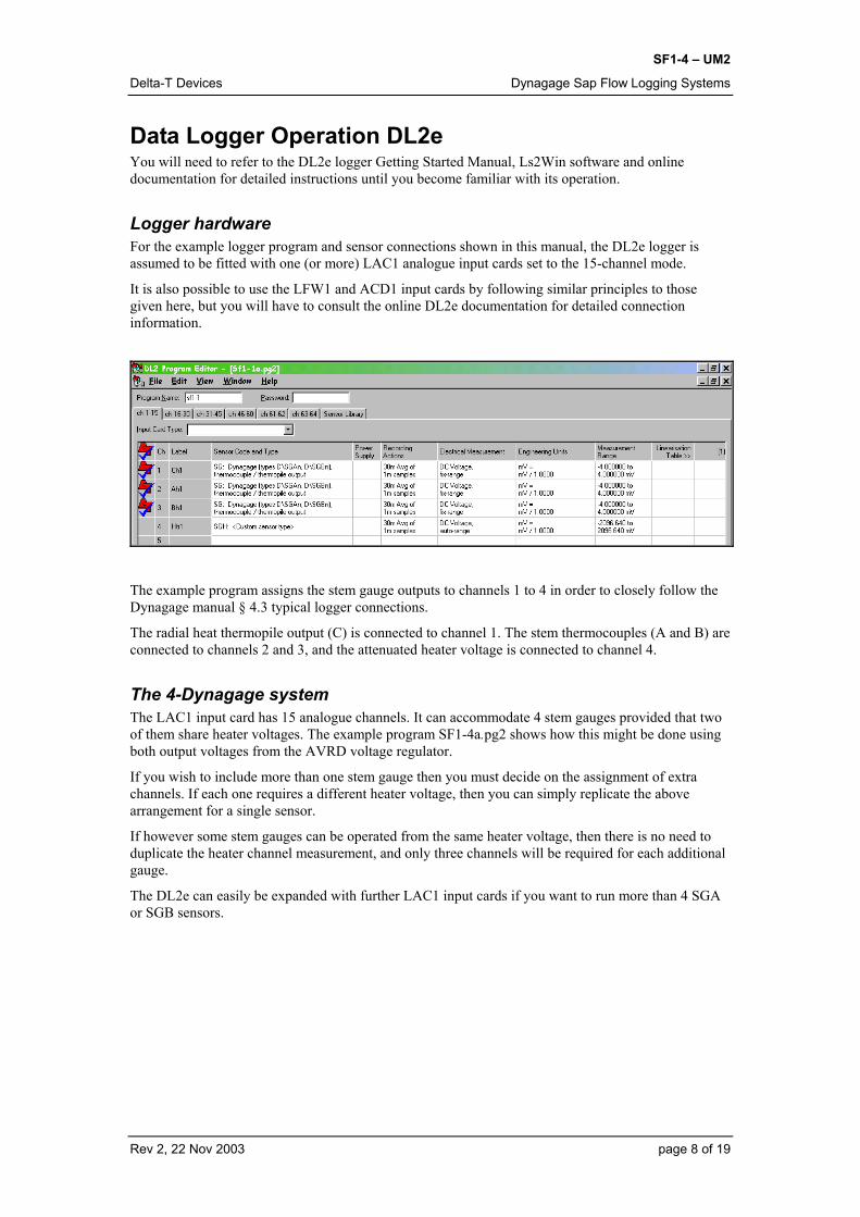
Logger hardware For the example logger program and sensor connections shown in this manual, the DL2e logger is assumed to be fitted with one (or more) LAC1 analogue input cards set to the 15-channel mode.
It is also possible to use the LFW1 and ACD1 input cards by following similar principles to those given here, but you will have to consult the online DL2e documentation for detailed connection information.
The example program assigns the stem gauge outputs to channels 1 to 4 in order to closely follow the Dynagage manual § 4.3 typical logger connections.
The radial heat thermopile output (C) is connected to channel 1. The stem thermocouples (A and B) are connected to channels 2 and 3, and the attenuated heater voltage is connected to channel 4.
The 4-Dynagage system The LAC1 input card has 15 analogue channels. It can accommodate 4 stem gauges provided that two of them share heater voltages. The example program SF1-4a.pg2 shows how this might be done using both output voltages from the AVRD voltage regulator.
If you wish to include more than one stem gauge then you must decide on the assignment of extra channels. If each one requires a different heater voltage, then you can simply replicate the above arrangement for a single sensor.
If however some stem gauges can be operated from the same heater voltage, then there is no need to duplicate the heater channel measurement, and only three channels will be required for each additional gauge.
The DL2e can easily be expanded with further LAC1 input cards if you want to run more than 4 SGA or SGB sensors.
Rev 2, 22 Nov 2003 page 8 of 19

SF1-4 – UM2
Delta-T Devices Dynagage Sap Flow Logging Systems
Modifying the DL2e program file When you have decided on the assignment of sensors to channels (you can of course add other types of sensors to any spare channels left on the LAC1 input card), then you must create a new program file.
You can load the above program file into the Ls2Win software, edit it, and then save it with a new program filename.
The Ls2Win software contains the sensor code SG for the thermocouple and thermopile outputs, and code SGH for the attenuated heater voltage.
If you are using the earlier DOS version of the LS2e software that does not already contain these in the sensor library, you can simply load the above program, and save the sensor to your sensor library. Otherwise, you can simply type in the details.
Sampling intervals and averaging periods You must also set the sampling interval and data compression period in the logger program file. The general considerations for these are given in the Dynagage manual § 6.5.1 and 6.5.5.
For short term experiments (1-2 days) then a 5-second sample rate is recommended. For longer term experiments (weeks) then 60 second sampling will reduce unnecessary power consumption.
For the averaging period 5 or 10-minute averages are appropriate for short term experiments, and half- or one hour periods for longer term studies. There is no fixed rule. In fact you are free to select any combination of sample and data compression interval that the DL2e will allow. There is always a trade-off between the amount of data produced, logger power consumption and data memory space.
System Assembly and Setup
Preliminary bench tests As with any complex system, you will probably want to test as many of the individual components as you can before setting up the whole installation in the field.
Rev 2, 22 Nov 2003 page 9 of 19

SF1-4 – UM2
Delta-T Devices Dynagage Sap Flow Logging Systems
It is not particularly easy to simulate the normal operation of stem gauges on the bench, however it is certainly possible to verify that the thermocouple and heater outputs are properly connected and read by the logger.
Program the logger First you must load the Ls2Win into your PC, and check its operation.
Then load the SF1-1.pg2 file, and after connecting the PC to your DL2e with the RS232 cable, send the program to the logger.
For initial “static” tests this will be sufficient. Later you will want to edit and refine the program before sending it to the logger once more.
Wiring connections
Signal HI, Bh (brown)Signal LO, common (white)
Heater V+ (red)Heater 0V (black)
Signal HI, Ah (green)Signal HI, Ch (blue)
Vsens+ (orange)Vsens- (yellow)
R
Screen Screen to Logger frame or 61- or 62-
DC POWER 6.5 to 28Vdc
25-500mA per gauge
+-
BK
– 61 + – 62 + 63 NO NC 64 NO NC
W
BL GN BN
4K99
15K
– 2 +– 1 + – 3 + – 4 + – 5 +
OY
VIN ? GND ? GND ?
VOUT2 ? VOUT1 ? CLINE ?
AVRD
1
2
OFFON
Single Stem Gauge Take one stem gauge (not attached to a stem) and your AVRD, and connect the extension cable to the DL2e screw terminal connector block as shown. If the attenuator resistors have been supplied loose, you must now connect them.
For the present DO NOT connect the heater 0V and V+ to the AVRD.
Rev 2, 22 Nov 2003 page 10 of 19

SF1-4 – UM2
Delta-T Devices Dynagage Sap Flow Logging Systems
Checking the thermocouple and thermopile outputs From the DL2e logger keypad, wake the logger and read the sensors on channels 1 to 3, read these directly on your PC under Ls2Win.
All the readings should be near 0.000 mV, and may be positive or negative, and gradually changing. Any large or rapidly fluctuating values indicate a lack of proper connection to the relevant channel. You must identify the source of the trouble and eliminate it.
Checking the heater voltage reading Before connecting the stem gauge heater wires to the AVRD, read all the warnings in the AVRD manual and the Dynagage manual § 6.4, and identify the correct heater voltage for your sensors.
Connect a suitable voltage supply to the AVRD, and switch it on. Set Vout1 to approximately the correct value (check this with a voltmeter if you can).
Switch the AVRD off. Then connect the heater 0V and V+ wires from your stem gauge. Switch on the AVRD briefly (10 seconds maximum), then off again.
Observe the reading of channel 4 on the logger. You should see a value attenuated by a factor of 4 (e.g. if Vout is set to 3.0 V, the logger reading will be 750 mV). Almost immediately the other channel readings for the stem gauge will start to move, in response to the temperature rise generated in the heater.
These simple checks broadly establish the satisfactory functioning of the stem gauge, logger and AVRD.
Checking Stem Gauge flow readings It is not easy to get realistic data readings from a stem gauge unless it is actually installed on a plant stem. Ideally you will want to practice installing these and taking real readings in order to become familiar with the practical techniques involved.
If you have access to a living plant stem of the appropriate diameter, you can install the stem gauge on it. Thoroughly read the Dynagage manual §5 before you attempt this.
You can use the existing connector wiring and logger program, but you may want to reduce the averaging period of the readings (to, say 10 minutes) so that you can see changes more quickly.
Once you have obtained some meaningful data from a real plant, you can then practice using the Excel spreadsheet provided on the software diskette to convert the data into readings of sap flow.
Rev 2, 22 Nov 2003 page 11 of 19

SF1-4 – UM2
Delta-T Devices Dynagage Sap Flow Logging Systems
Wiring Harness: 4-Dynagage system
The wiring harness shown above implements the 4-Dynagage logger program (Sf1-4.pg2) within the Delta-T M2-ENCL enclosure. The physical layout of the main components is indicated diagrammatically.
A single external power supply (nominal 12 V) powers the logger and the stem gauge heaters through the AVRD. The logger can also contain its own internal alkaline batteries which will power the logger (only) if the external supply fails or is disconnected for any reason.
Rev 2, 22 Nov 2003 page 12 of 19
SF1-4 – UM2
Delta-T Devices Dynagage Sap Flow Logging Systems
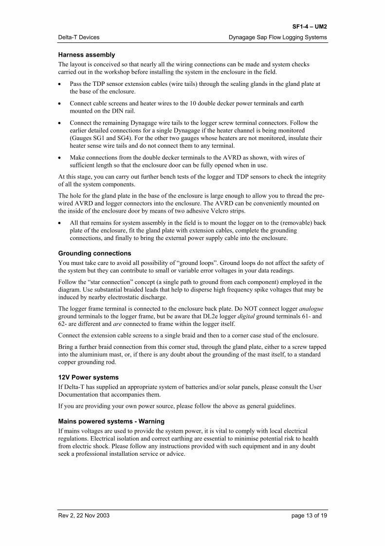
Harness assembly The layout is conceived so that nearly all the wiring connections can be made and system checks carried out in the workshop before installing the system in the enclosure in the field.
• Pass the TDP sensor extension cables (wire tails) through the sealing glands in the gland plate at the base of the enclosure.
• Connect cable screens and heater wires to the 10 double decker power terminals and earth mounted on the DIN rail.
• Connect the remaining Dynagage wire tails to the logger screw terminal connectors. Follow the earlier detailed connections for a single Dynagage if the heater channel is being monitored (Gauges SG1 and SG4). For the other two gauges whose heaters are not monitored, insulate their heater sense wire tails and do not connect them to any terminal.
• Make connections from the double decker terminals to the AVRD as shown, with wires of sufficient length so that the enclosure door can be fully opened when in use.
At this stage, you can carry out further bench tests of the logger and TDP sensors to check the integrity of all the system components.
The hole for the gland plate in the base of the enclosure is large enough to allow you to thread the pre-wired AVRD and logger connectors into the enclosure. The AVRD can be conveniently mounted on the inside of the enclosure door by means of two adhesive Velcro strips.
• All that remains for system assembly in the field is to mount the logger on to the (removable) back plate of the enclosure, fit the gland plate with extension cables, complete the grounding connections, and finally to bring the external power supply cable into the enclosure.
Grounding connections You must take care to avoid all possibility of “ground loops”. Ground loops do not affect the safety of the system but they can contribute to small or variable error voltages in your data readings.
Follow the “star connection” concept (a single path to ground from each component) employed in the diagram. Use substantial braided leads that help to disperse high frequency spike voltages that may be induced by nearby electrostatic discharge.
The logger frame terminal is connected to the enclosure back plate. Do NOT connect logger analogue ground terminals to the logger frame, but be aware that DL2e logger digital ground terminals 61- and 62- are different and are connected to frame within the logger itself.
Connect the extension cable screens to a single braid and then to a corner case stud of the enclosure.
Bring a further braid connection from this corner stud, through the gland plate, either to a screw tapped into the aluminium mast, or, if there is any doubt about the grounding of the mast itself, to a standard copper grounding rod.
12V Power systems If Delta-T has supplied an appropriate system of batteries and/or solar panels, please consult the User Documentation that accompanies them.
If you are providing your own power source, please follow the above as general guidelines.
Mains powered systems - Warning If mains voltages are used to provide the system power, it is vital to comply with local electrical regulations. Electrical isolation and correct earthing are essential to minimise potential risk to health from electric shock. Please follow any instructions provided with such equipment and in any doubt seek a professional installation service or advice.
Rev 2, 22 Nov 2003 page 13 of 19

SF1-4 – UM2
Delta-T Devices Dynagage Sap Flow Logging Systems
Field installation The initial setting up of your experiment will require the following steps:
• Install the enclosure
• Install the logger, AVRD, and stem gauge extension cables in the enclosure
• Install the gauges on the stems, and connect to their extension cables
• Set up the external power supply.
Before switching on the external power to the gauge heaters, you can do preliminary checks of all the sensors via the front panel display on the DL2e logger (or by interrogating the logger with a portable PC). Make sure that the voltage levels Vout1 and Vout2 are set approximately correct for your particular gauges.
If you experience difficulties, do refer back to the Dynagage manual §5 & 6 that contain very useful guidance on locating and eliminating sources of error.
Start logging data and then switch on the AVRD. Monitor the heater voltage channels to check that the heaters are receiving the correct voltage.
After your logger has had time to record two or three averaging periods, you can download the data from the logger to a PC (or to a Psion Workabout using the Delta-T Attach software). Then do a preliminary inspection of the data for any obvious errors or difficulties.
During the next few days, you will inspect and analyse the data in order to fine-tune the heater voltage levels (see Dynagage manual §3.2.1) and other practical aspects of the sensors fit and insulation of the plant stems. When these matters have been satisfactorily resolved the daily attention can be relaxed, but you would be well advised to check every two or three days if possible.
Rev 2, 22 Nov 2003 page 14 of 19

SF1-4 – UM2
Delta-T Devices Dynagage Sap Flow Logging Systems
Data Processing The “raw” millivolt readings from the stem gauges must be processed to give values of sap flow. For your convenience an Excel spreadsheet has been set up in which includes the necessary calculations. The theoretical basis for the formulae used is covered in detail in the Dynagage manual §4.
Using Ls2Win with Excel for data files The DL2e data logger can produce data files in either binary (*.bin) or ASCII (*.dat) format. (The fastest way of collection is binary format).
Getting the data file into Excel The most efficient method to achieve this is using the Import Dataset Wizard that is supplied with Ls2Win. Excel supports this function as standard; and is accessed by clicking on Import Dataset(s) … from the “File” tab.
After this choice has been made, the Import Data Wizard dialog window appears, with self explanatory instructions with easy to follow menus. Complete the instructions in each window to create excel spreadsheets and graphical analysis as required.
The sap flow spreadsheet The file DGCALCx.xls is included on the Sap Flow software diskette. It is an Excel workbook saved in Excel 5 format. It has been annotated and designed with a minimum of complex features, so that a relatively inexperienced Excel user will be able to copy and modify it without difficulty.
The workbook contains two sheets. The first sheet, named “Calcn” is the one you will routinely use for processing data from each stem gauge. A printout of this sheet is included at the end of this manual.
The second sheet is an example with real stem gauge data taken not from a real stem but from a simulated stem through which the flow was actually measured. It is included for interest because it shows an agreement within 5% of the measured and calculated flows – validating both the theory and the actual implementation of the formulae used in the spreadsheet.
Rev 2, 22 Nov 2003 page 15 of 19

SF1-4 – UM2
Delta-T Devices Dynagage Sap Flow Logging Systems
The sap flow calculation On the Calcn sheet, you will find brief explanations of all the parameters that must be specified, and the operations to calculate sap flow.
You will need to start a sheet like this, in its unmodified form, for each Dynagage sensor, so it is a good idea to copy the sheet immediately, rename the new sheet and use that.
In column B you must input important factors specific to an individual Dynagage. For your first trial, you must put your best estimates in the Gauge and Stem parameters cells, and you must specify the correct reading interval of your data (the time between the successive rows of your data).
Now copy from the .xls data file you have just prepared the columns of data corresponding to columns A:J. If your Dynagage was connected to channels 1 to 4 on the DL2e logger, these will be the identical group of columns A:J in your data spreadsheet, otherwise you will have to choose the appropriate columns.
It is good practice to routinely include the error flag columns associated with the data, and not to ignore them. This can help in interpretation of data calculations later.
After you have copied the formula cells in columns L:X into all the rows below to the full extent of your data, you should obtain a complete sheet of figures.
Do not be worried at this stage if some of the cells are reporting errors; the columns L:P (power and dT calculations) should however be giving sensible results.
Don’t omit to save your spreadsheet files complete. They can be used for data archiving, and you can always return to them later if you wish to recalculate sap flow values with revised parameters.
Setting values for Ksh For the next stage of the analysis you must refer once again to the Dynagage manual theory §4, and in particular to §4.4 and §7.5 onwards. You must inspect the values of KshApp overnight and use these to overwrite the value of KshInUse, in accordance with Dynamax’s recommendations. This should then produce some sensible values of the sap flow rate during most of the daylight hours.
Applying flow filter conditions The final stage of the process is to analyse the unrealistic or erroneous values of flow rates, otherwise the accumulating sap flow amount (Facc) can be considerably in error.
In addition, you must reset to zero the Facc accumulator from time to time (e.g. daily or weekly) as you prefer. This is done by overwriting the appropriate cells in column X with the value zero.
Various filters can be applied to some of the calculated parameters. These are discussed in §4.5 onwards. Generally speaking, these filters work satisfactorily much of the time, and you do have the freedom to adjust some of the conditional values. However, the filters are not completely robust, and . you may still need to apply common sense interpretations to some data. See also §8.4-8.6 for a discussion of other phenomena that may be encountered at sun-up, or at other times.
SGA2&3 Micro sensors If you are using the very small Micro sensors which have a slightly different construction (only one pair of thermocouples), you must use a dummy value of dX=1 mm. The Dynagage manual §3.3 explains their special requirements.
Graphing sap flow Excel’s graphing facilities are very powerful, and well repay the time spent learning how to use them effectively. You should quite quickly be able to construct charts showing any aspect of your data. No chart template has been provided.
Recalculating sap flow with new parameters The need for retrospective recalculation of sap flow is discussed in the Dynagage manual § 8.3. If you have saved your earlier calculations as Excel spreadsheets, you should have no difficulty in reworking these with revised parameter values.
Rev 2, 22 Nov 2003 page 16 of 19

SF1-4 – UM2
Delta-T Devices Dynagage Sap Flow Logging Systems
Warranty and Service
Terms and Conditions of Sale Our Conditions of Sale (ref: COND: 1/00) set out Delta-T's legal obligations on these matters. The following paragraphs summarise Delta-T's position but reference should always be made to the exact terms of our Conditions of Sale, which will prevail over the following explanation. Delta-T warrants that the goods will be free from defects arising out of the materials used or poor workmanship for a period of twelve months from the date of delivery. Delta-T shall be under no liability in respect of any defect arising from fair wear and tear, and the warranty does not cover damage through misuse or inexpert servicing, or other circumstances beyond our control. If the buyer experiences problems with the goods they shall notify Delta-T (or Delta-T’s local agent) as soon as they become aware of such problem. Delta-T may rectify the problem by supplying faulty parts free of charge, or by repairing the goods free of charge at Delta-T's premises in the UK, during the warranty period, If Delta-T requires that goods under warranty be returned to them from overseas for repair, Delta-T shall not be liable for the cost of carriage or for customs clearance in respect of such goods. However, we much prefer to have such returns discussed with us in advance, and we may, at our discretion, waive these charges. Delta-T shall not be liable to supply products free of charge or repair any goods where the products or goods in question have been discontinued or have become obsolete, although Delta-T will endeavour to remedy the buyer’s problem. Delta-T shall not be liable to the buyer for any consequential loss, damage or compensation whatsoever (whether caused by the negligence of the Delta-T, our employees or agents or otherwise) which arise from the supply of the goods and/or services, or their use or resale by the buyer. Delta-T shall not be liable to the buyer by reason of any delay or failure to perform our obligations in relation to the goods and/or services, if the delay or failure was due to any cause beyond the Delta-T’s reasonable control.
Service and Spares Users in countries that have a Delta-T Agent or Technical Representative should contact them in the first instance. Spare parts for our own instruments can be supplied from our works. These can normally be despatched within a few working days of receiving an order. Spare parts and accessories for sensors or other products not manufactured by Delta-T, may have to be obtained from our supplier, and a certain amount of additional delay is inevitable. No goods or equipment should be returned to Delta-T without first obtaining the agreement of Delta-T or our agent. On receipt at Delta-T, the goods will be inspected and the user informed of the likely cost and delay. We normally expect to complete repairs within a few working days of receiving the equipment. However, if the equipment has to be forwarded to our original supplier for specialist repairs or recalibration, additional delays of a few weeks may be expected.
Rev 2, 22 Nov 2003 page 17 of 19
SF1-4 – UM2
Delta-T Devices Dynagage Sap Flow Logging Systems
Troubleshooting
Routine Maintenance In general, SGA/B sap flow systems are simple to operate once the initial installation has been satisfactorily achieved. As with all field set-ups, visual inspection of the site and data collection every few days is the ideal way to track down problems quickly and avoid loss of data.
If problems occur, you must try to identify which components are the source of the trouble, and then consult the relevant documentation.
For sap flow systems questions, consult this manual.
For the SGA/B sensors operation and installation, consult the Dynagage Manual.
For the AVRD, consult the AVRD Manual.
For the DL2e logger, power supplies and other sensors supplied by Delta-T, please consult the relevant User Manual or user documentation provided.
Technical Support Technical Support is available on Delta-T products and systems. Users in countries that have a Delta-T Agent or Technical Representative should contact them in the first instance. Technical Support questions received by Delta-T will be handled by our Tech Support team. Your initial enquiry will be acknowledged immediately with a “T number” and an estimate of time for a detailed reply (normally a few working days). Make sure to quote our T number subsequently so that we can easily trace any earlier correspondence. In your enquiry, always quote instrument serial numbers, software version numbers, and the approximate date and source of purchase where these are relevant.
Contact details:
Tech Support Team Delta-T Devices Ltd 128 Low Road, Burwell, Cambridge CB5 0EJ, U.K. email: [email protected] Web site: www.delta-t.co.uk Tel: +44 (0) 1638 742922 Fax: +44 (0) 1638 743155
Rev 2, 22 Nov 2003 page 18 of 19

SF
1-4
– U
M2
Del
ta-T
Dev
ices
D
ynag
age
Sap
Flow
Log
ging
Sys
tem
s
Sap
Flow
spr
eads
heet
(prin
tout
)
1 2 3 4 5 6 7 8 9 10 11 12 13 14 15 16 17 18 19 20 21 22 23 24 25 26 27 28 29 30 31 32
AB
CD
EF
GH
IJ
KL
MN
OP
QR
ST
UV
WX
DL2
e D
ynag
age
Sap
Flow
com
puta
tion
Gau
ge a
nd s
tem
par
amet
ers:
Inpu
t:Fo
rmul
ae (S
ee m
anua
l):Im
plem
enta
tion
(not
e m
m/m
, s/h
and
min
/h fa
ctor
s w
here
app
ropr
iate
)S
eria
l No.
SG
B25
#1Y
our D
ynag
age
iden
tifie
rP
in=(
Vin
/Atte
nuat
or)^
2/R
esis
tanc
e(J
31/1
000/
$B$6
)^2/
$B$4
Res
ista
nce
43oh
ms
Its h
eate
r res
ista
nce
Qv=
Kst
*A*(
Bh-
Ah)
/dX
/0.0
40/1
0$B
$8*$
B$7
*(H
31-F
31)/0
.04/
$B$5
/10
dX7
mm
Its
ther
moc
oupl
e se
para
tion
Qr=
Ksh
InU
se*C
hQ
31*D
31A
ttenu
ator
0.25
Its d
ivid
er a
ttenu
ator
R1/
(R1+
R2)
Qf=
Pin
-Qv-
Qr
L31-
M31
-N31
A5.
3cm
2S
tem
cro
ss s
ectio
n ar
eadT
= (A
h+B
h)/2
/0.0
40(F
31+H
31)/2
/0.0
4K
st0.
42W
.m-1
.K-1
Ste
m th
erm
al c
ondu
ctan
ce:
Ksh
InU
se=
set b
y us
er (0
.8 d
efau
lt)0.
8Fi
lter c
ondi
tions
: 0
.54
herb
aceo
us, 0
.42
woo
dy ,
0.28
hol
low
Ksh
App
=(P
in-Q
v)/C
h(L
31-M
31)/D
31Lo
w F
low
:Fl
ow=Q
f/Cp/
dTO
31/4
.186
/P31
*360
0Q
f <0
App
aren
t ne g
ativ
e flo
w. R
etur
n ze
ro.
IF(O
31<0
,0,""
)Q
f/Pin
<20
%If
this
and
nex
t are
true
, flo
w v
alue
s to
o lo
w. R
etur
n ze
ro.
IF(A
ND
(O31
>0,O
31<$
B$1
2/10
0*L3
1,P
31<$
B$1
3),0
,"")
(DTM
IN) d
T <
0.
75de
g C
Hig
h Fl
ow:
dT<
0.25
deg
CIf
true,
flow
erro
rs m
ay b
e ve
ry la
rge.
Ret
urn
Fmax
IF(S
31>$
B$1
6*$B
$7,$
B$1
6*$B
$7,""
)V
max
152
cm/h
Max
imum
flow
vel
ocity
(any
ste
m).
Fmax
=Vm
ax*A
.D
ata:
FiltF
low
=0, o
r Flo
w, o
r Fm
ax if
less
IF(S
31<0
,0,M
IN(S
31:V
31))
Rea
ding
inte
rval
5m
inut
esY
our d
ata
read
ing
inte
rval
Facc
=Pre
viou
s+In
crem
ent
X30
+W31
*($B
$18/
60)
Spr
eads
heet
ope
ratio
n1.
Ent
er y
our g
auge
and
ste
m p
aram
eter
s an
d da
ta re
adin
g in
terv
al in
col
umn
B.
2. L
eave
filte
r con
ditio
ns a
s su
gges
ted.
3. C
opy
your
dat
a in
to c
olum
ns A
:J fr
om ro
w X
XX
dow
nwar
ds. (
Ove
rwrit
e A
31:J
31)
4. C
opy
the
form
ulae
in ro
w X
XX
col
umns
L:X
into
the
row
s be
neat
h.5.
Obs
erve
the
valu
e of
Ksh
App
. Adj
ust K
shIn
Use
if n
eces
sary
. (S
ee m
anua
l) 6.
Obs
erve
the
Filte
r col
umns
. Che
ck v
alid
it y. C
onsi
der f
ilter
val
ues.
(See
man
ual)
7. R
ow 0
00 s
ets
flow
acc
umul
ator
to 0
Fi
lter
Filte
rFi
lter
Dat
e/tim
eC
hA
hB
hV
inP
inQ
vQ
rQ
fdT
Ksh
InU
seK
shA
ppFl
owFc
nd<0
Fcnd
Low
Fcnd
Hi
FiltF
low
Facc
(any
form
at)
mV
mV
mV
mV
WW
WW
deg
CW
/mV
W/m
Vg/
hg/
hg/
hg/
hg/
hg
000
0.0
21/0
3/99
10:
40X
XX
0.23
400.
0670
0.08
7010
69.0
0.42
521
0.01
590
0.18
720
0.22
211
1.93
0.80
01.
749
99.2
99.2
8.3
Rev
2, 2
2 N
ov 2
003
page
19
of 1
9


