Abstract. The dynamic characteristics of squeeze piezo printhead are studied using reduced frequency model for inks with different viscosity. While piezo inkjet mainly applies in paper printing and graphic output, many new applications have emerged in the last few years. These new applications involve inks with high viscosity. Ink viscosity is a key material parameter in printhead design. In order to take viscous damping into account, reduced frequency model is applied to model the printhead fluid cavity. Squeeze piezo printhead models with different inks (viscosity range from 20 cps to 110 cps) are built using software ANSYS15.0. Meniscus velocity and pressure at the nozzle entrance excited by frequency from 10 KHz to 200 KHz are calculated. Meantime, the velocity and pressure distribution around the first resonant frequency (which is 21250 Hz in the paper) are also calculated. The results reveal that both meniscus velocity and pressure decrease with increasing viscosity. It is notable that ink viscosity affects the printhead dynamic response significantly near resonant frequency. When the exciting frequency is far from resonant frequency, the influence of viscosity is small. The reduced frequency model is a powerful tool for the design optimization of the piezo printhead.
1. Introduction
Piezo printing has major applications in paper printing and graphic output for now. However, more and more researchers are getting interested in using piezo printing to manufacture complex components for applications in fields such as displays [1], plastic electronics [2], tissue engineering [3, 4]. A significant and fundamental difference between these new applications and the traditional application of paper printing is that the “ink” used in these new applications always have more complex fluid properties such as non-continuous, non-Newtonian and highly viscous. In order to study the printing theory and develop new piezo printhead used in the emerging fields [4], it is essential to capture and control the flow phenomena in piezo printhead during inkjet process.
Many studies about the theme are published and most are carried out through experimental method [5-7]. Because piezo printhead generally has small dimension, the experiments are always expensive. Meantime, piezo ink printing involves several physical processes [8]. It is hard to conclude useful rule for different ink printing from experiments.
Computer simulation is also a powerful method to study piezo printhead [9]. Because physical processes including piezoelectricity, structure dynamics, acoustics and fluid dynamics are involved. The complete simulation model must be multi-fields coupled. While coupled model generally is hard to build and time-consuming to solve, sequential method, which featured that results from one fields are input as loads for the next fields, are popular and appropriate under most circumstances.
There are several models to simulate the generation and propagation of pressure wave in the printhead fluid cavity. Full Navier-Stokes equation, which is the most fundamental and execute model theoretically, is very time consuming and few researchers try to apply it. Pure acoustic theory is much simpler, but the viscous damping effects are neglect, while the viscous damping is essential for small section cavity flow. Reduced frequency model, which is also known as narrow channel
4th International Conference on Electrical & Electronics Engineering and Computer Science (ICEEECS 2016)
theory, is a simplified version of more general Navier-Stokes equation in the printhead analysis. Features of very small section dimension compared to axial one is taken into account. The theory is first developed for calculating acoustics in narrow gap [10]. The simplified model is much cheaper than general Navier-Stokes equation for narrow channel flow. Especially the viscous damping of the ink is taken into account and the resulted fluid cavity flow field generally is more execute compared with pure acoustic simulation.
In this paper, the piezo printhead are simulated using sequential coupled method. Structure FE model (including Piezo actuator and lining) is built and solved firstly. The resulted inner wall displacement is input as load in the next reduced frequency fluid cavity simulation. With different exciting frequency, pressure and velocity distribution in the fluid cavity are calculated. Pressure at the nozzle entrance (Pn) and meniscus velocity (Vm) are most important index in printhead design. Effects of the fluid viscosity on Pn and Vm are also studied. The whole simulation is carried out using software ANSYS 15.0.
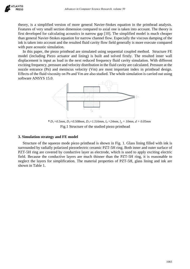
Structure of the squeeze mode piezo printhead is shown in Fig. 1. Glass lining filled with ink is surrounded by radially polarized piezoelectric ceramic PZT-5H ring. Both inner and outer surface of PZT-5H ring are covered by conductive layer as electrode, which is used to apply exciting electric field. Because the conductive layers are much thinner than the PZT-5H ring, it is reasonable to neglect the layers for simplification. The material properties of PZT-5H, glass lining and ink are shown in Table 1.
Viscosity 20×10-3 ~110×10-3pa ▪s In order to simplify the simulation, a printhead structure simulation is carried out first. The
resulted inner wall displacement is used as load input for next fluid cavity RF model. ANSYS APDL introduced the advanced RF model in version 15.0 and the platform is used in this
study. As shown in Fig. 2, coupled field element SOLID226 and structure element SHELL 281 are used to simulate the PZT-5H ring and glass lining respectively. The FE model and boundary conditions for piezo structure analysis show in Fig. 2(a) and Table 2 respectively.
Table. 2 FE model BCs of piezo structure analysis
A B C VOLT=0V
Free Coupled VOLT
VOLT=12V Free
Coupled VOLT
Free
D E Free Clamped
Fig. 2 FE models for structure simulation (a) and the fluid cavity (b).
Element FLUID220 is selected for simulate the fluid domain. It is noteworthy that channel shape and dimension need to be specified explicitly using material properties with RF model in ANSYS. Because the nozzle has a conical shape and its radius is different along longitudinal direction. In order to model the nozzle precisely, layer of 0.15 mm is used to divide the conical into a series of cylinder part, which are simulated with corresponding radius (Fig. 2(b)). Reduced frequency model is flagged
Advances in Computer Science Research, volume 50
1084
on. FSI interface and inner wall radial displacement calculated in the former structure analysis are applied on the interface. Because the radius of fluid cavity is very small, gravity is ignored in the model and reservoir has much larger volume than the fluid cavity. The boundary conditions of both interface (surface F) and the meniscus are set as zero pressure (Table. 3).
Table. 3 Boundary Conditions of Fluid Cavity RF models Surface A, C and D Surface B Surface E and F
UY = 0; UZ=0 ROTX=0; ROTY=0;
ROTZ=0 SFI flag on
UX = Disp_Wall; UY = 0; UZ=0 ROTX=0; ROTY=0; ROTZ=0
SFI flag on PRES = 0
※ All the displacement are specified in cylinder coordinate shown in Fig. 2(b).
4. Result and analysis
4.1 Results of structure simulation The printhead structure simulation is carried out firstly. Deformation of the structure excited by
12V voltage is calculated (as shown in Fig. 3). Inner wall radial displacement Disp_Wall is key quantity as load input in the next RF simulation. In this case, the Disp_Wall is 14 nm.
Fig. 3 Printhead deformation excited by 12V voltage
The paper is focused on the topic how viscosity affect the printhead dynamic properties and ink viscosity has negligible influence on the structure deformation. Therefore, in the following simulation, constant inner wall displacement Disp_Wall is applied. 4.2 Results of fluid simulation
Fig. 4 Relationships of Vm, Pn and frequency
Harmonic simulations for various viscosities (from 20 cps to 110 cps with step 10) are carried out. The sweeping frequency is from 10K Hz to 200K Hz, which is the typical piezo printhead working
Advances in Computer Science Research, volume 50
1085
frequency. Through the simulation, the frequency response of meniscus velocity Vm and pressure at the nozzle entrance Pn for various are calculated (Fig. 4).
It is obvious that the viscosity has the most significant impact on both Vm and Pn around resonant frequency. When the exciting frequency is far from resonant frequency, the Vm and Pn are almost the same for all the simulated viscosity. However, in order to enhance piezo printhead performance, actual working frequency is always selected around resonant frequency.
Table. 4 Vm and Pn for various viscosities at the first resonant frequency (21250 Hz) Viscosity/cps 20 30 40 50 60
Pn/pa 265638 237961 209755 192616 174792 It is essential to get insight how viscosity affect the value of Vm and Pn around resonant frequency.
A second harmonic analysis around the first resonant frequency (from10K Hz to 40K Hz) is carried out to capture the variation tendency details of Vm and Pn. And the detailed frequency response graphs (Fig. 5) show that values of both Vm and Pn decrease with increasing ink viscosity.
Since both Vm and Pn curves for large viscosity are flat compared to ones for small viscosity. It is safe to say that through low viscous ink can achieve higher Vm and Pn, the performance are more sensitive to exciting frequency and working frequency and exciting wave shape must be selected carefully.
Meantime, viscosity did not affect the resonant frequency (21250 Hz for this case). Values of Vm and Pn for different viscosity at the resonant frequency are listed in the Table 5. One would expect the viscosity to affect the damping (which decreases the values of Vm and Pn), but not the resonant frequency. Because the simulation neglect glass lining in the RF model, it is notable the resulted Vm and Pn are larger than the real values. The result can be used as upper limits.
Fig. 5 Meniscus velocity (a) and pressure at nozzle entrance (b) frequency responses around the first
resonance frequency 4.3 Results for velocity and pressure distribution near resonant frequency
The details of velocity (v) and pressure (p) distribution in the piezo printhead fluid cavity are helpful for printhead design and optimization. From the former harmonic analysis, it can be concluded that the meniscus achieves largest velocity value when the exciting load is at the first resonant frequency, which is 21250 Hz for the studied printhead. Velocity and pressure distribution near 21250 Hz for different viscous ink are presented in the following analysis.
Advances in Computer Science Research, volume 50
1086
Fig. 6Curves of Vm- Z (a) and Pn-Z (b)
A coordinate as shown in Fig. 2 is specified in the following analysis. Z-axis coincides with the central axis of the fluid cavity. From the curves of P-z and V-z (Fig. 6) at different viscosity and exciting frequency, it is obvious that neither ink viscosity nor exciting frequency, which is near resonant point, affects p and V tendency along Z direction. Only p and V values are affected by ink viscosity and exciting frequency. Viscosity affects the V, and p significantly, especially within the nozzle. Both V and P decrease with increasing viscosity. For high-viscosity case, the values of V and p are not as sensitive to the exciting frequency as for low-viscosity case (also shown in Fig. 5(b)). Both V and p change dramatically within the nozzle. Contour of V and p are presented in Fig. 7.
Fig. 7 Contours of V (a) and P (b)
5. Conclusion
This research has built a reduced frequency simplified simulating model for the squeeze mode piezo printhead. The simplified model is then used to study the dynamic characteristics of the printhead fluid cavity. Various inks with different viscosity are simulated to study how viscosity affects the fluid cavity frequency response. Meniscus velocity Vm and pressure at nozzle entrance Pn are key quantities in the research and they are calculated using the simplified model. The distribution of pressure and velocity near the resonant frequency are also presented in paper. Simulation results reveal the meniscus velocity and pressure at nozzle entrance are affected by viscosity near resonant frequency significantly and it is important to take a full account of viscosity when one designs a new piezo printhead. The presented model is a powerful tool to evaluate the viscosity effect and it also has great potential to be extended for the design optimization of the piezo printhead.
Advances in Computer Science Research, volume 50
1087
Acknowledgements This project is sponsored by the National Natural Science Foundation of China, (Grant No.
51175432), the Doctor Special Science and Technological Funding of the China Ministry of Education (Grant No. 20116102110046), the Fundamental Research Funds for the Central Universities (Grant No. 3102014JCS05007), the key Industrial Science and technology projects of Shaanxi (No.2015GY047), and the Xinjiang Uygur Autonomous Region science and technology project (Grant No. 201130112).
References:
[1] Kong YL, Tamargo IA, Kim H, Johnson BN, Gupta MK, Koh TW, et al. 3D printed quantum dot light-emitting diodes [J]. NANO LETT. 2014, 14(12): 7017-7023.
[2] Hübler AC, Schmidt GC, Kempa H, Reuter K, Hambsch M, Bellmann M. Three-dimensional integrated circuit using printed electronics [J]. ORG ELECTRON. 2011, 12(12): 419-423.
[3] Murphy SV, Atala A. 3D bioprinting of tissues and organs [J]. NAT BIOTECHNOL. 2014, 32(8):773-785.
[4] Singh M, Haverinen HM, Dhagat P, Jabbour GE. Inkjet Printing: Inkjet Printing-Process and Its Applications [J]. ADV MATER. 2010, 22(6): 673-685.
[5] Derby B. Bioprinting: inkjet printing proteins and hybrid cell-containing materials and structures [J]. Journal of Materials Chemistry. 2008, 18(47): 5717.
[6] Shin P, Lee S, Sung J, Kim JH. Operability diagram of drop formation and its response to temperature variation in a piezoelectric inkjet nozzle [J]. MICROELECTRON RELIAB. 2011, 51(2): 437-444.
[7] Zhou Q, Lau S, Wu D, Kirk Shung K. Piezoelectric films for high frequency ultrasonic transducers in biomedical applications [J]. PROG MATER SCI. 2011, 56(2): 139-174.
[8] Wijshoff H. The dynamics of the piezo inkjet printhead operation☆ [J]. Physics Reports. 2010, 491(4-5): 77-177.
[9] Desai S, Lovell M, Cordle J. Coupled field analysis of a piezoelectric bimorph disc in a direct write process [J]. Composites Part B: Engineering. 2007, 38(7-8): 824-832.
[10] Beltman WM. Viscothermal wave propagation including acousto-elastic interaction, part II: applications [J]. Journal of Sound and Vibration. 1999, 227(3): 587-609.