Dynamic behavior of a multi-tasking reactive distillation column for production of silane, dichlorosilane and monochlorosilane César Ramírez-Márquez a , Eduardo Sánchez-Ramírez a , Juan José Quiroz-Ramírez a , Fernando I. Gómez-Castro a , Nelly Ramírez-Corona b , Jorge A. Cervantes-Jauregui c , Juan Gabriel Segovia-Hernández a, * a Universidad de Guanajuato, Departamento de Ingeniería Química, Noria Alta s/n 36050, Guanajuato, Gto., México b Universidad de las Américas Puebla, Departamento de Ingeniería Química, Alimentos y Ambiental, Ex Hacienda Sta. Catarina Mártir 72820, San Andrés Cholula, Puebla, México c Universidad de Guanajuato, Departamento de Química, Noria Alta s/n, 36050, Guanajuato, Gto., México A R T I C L E I N F O Article history: Received 28 April 2016 Received in revised form 27 July 2016 Accepted 8 August 2016 Available online 9 August 2016 Keywords: Reactive distillation Multitasking column Silane Control properties A B S T R A C T Solar cell manufacturing is based on solar grade silicon which can be obtained using silane as precursor. Silane is produced by redistribution reactions of trichlorosilane. The aim of the present work is to study the control properties of a multitasking reactive distillation column to produce silane, dichlorosilane and monochlorosilane. Control adjustment was defined in such way that the column may work in multitasking mode producing the three interest components in high purity. Several control strategies were studied to define the best dynamic performance which allow to produce those three components within the same column. In order to observe the dynamic behavior of the multitasking reactive distillation column, this system was tested under various control strategies: temperature, composition and cascade (temperature/composition), having as target to keep silanes purity in 99.5%mol. The results indicated that is possible to obtain a conceptual design of a single reactive distillation column which would be able to produce all products. The proposed multitasking column avoids all hurdles involved in the traditional way to produce and purify all those three components. It was observed those evaluated control structures can stabilize the system against tested disturbances, even the simplest temperature control structure. ã 2016 Elsevier B.V. All rights reserved. 1. Introduction Globally, since reserves of crude oil are continuously decreasing there is an increasing interest of having other kind of energy sources, mainly renewable, clean and environmental friendly. Currently, several research groups are focus on finding a competitive energy source in comparison with fossil fuels. Solar photovoltaic energy as well as other renewable energy sources are attempting to diminish the energetic dependence of fossil fuels. Moreover, wind, hydroelectric and solar energies have been recently relevant. Particularly, solar energy has been exploiting in many ways, the most known method is to use solar cells based in silicon, which transform solar light into electricity through the photovoltaic effect (PV). The growing interest to obtain silicon as raw material for solar cells has evolved significantly in recent decades [1] . It is expected a growing demand of 30% per year for the next 10 years [2]. A more detailed analysis indicates that photovoltaic market has increased an average rate of 45% per year over the past decade showing a major demand between 2007 and 2011, up to 70% per year; with a decrease of 15% in 2012 because some european countries reduced the incentives for its implementation. Al- though several reports indicate continuous growing in this sector, the entire capacity installed in 2011 was 27 GW which only represents 1% of the total energy production considering all available sources [3] . Even when silicon solar cells are competing with other kind of cells made of advanced material, it has predicted that silicon solar cells will continue making an important contribution to the market depending on the maturity of the technology, its availability and especially its cost [4]. For such reasons, the assessment of new alternatives for its production with competitive costs constitutes an area of opportunity for research in solar technology [3,4] * Corresponding author E-mail addresses: [email protected], [email protected](J.G. Segovia-Hernández). http://dx.doi.org/10.1016/j.cep.2016.08.005 0255-2701/ã 2016 Elsevier B.V. All rights reserved. Chemical Engineering and Processing 108 (2016) 125–138 Contents lists available at ScienceDirect Chemical Engineering and Processing: Process Intensification journal homepa ge: www.elsev ier.com/locate/cep
Transcript
Chemical Engineering and Processing 108 (2016) 125–138
Dynamic behavior of a multi-tasking reactive distillation column forproduction of silane, dichlorosilane and monochlorosilane
César Ramírez-Márqueza, Eduardo Sánchez-Ramíreza, Juan José Quiroz-Ramíreza,Fernando I. Gómez-Castroa, Nelly Ramírez-Coronab, Jorge A. Cervantes-Jaureguic,Juan Gabriel Segovia-Hernándeza,*aUniversidad de Guanajuato, Departamento de Ingeniería Química, Noria Alta s/n 36050, Guanajuato, Gto., MéxicobUniversidad de las Américas Puebla, Departamento de Ingeniería Química, Alimentos y Ambiental, Ex Hacienda Sta. Catarina Mártir 72820, San AndrésCholula, Puebla, MéxicocUniversidad de Guanajuato, Departamento de Química, Noria Alta s/n, 36050, Guanajuato, Gto., México
A R T I C L E I N F O
Article history:Received 28 April 2016Received in revised form 27 July 2016Accepted 8 August 2016Available online 9 August 2016
Solar cell manufacturing is based on solar grade silicon which can be obtained using silane as precursor.Silane is produced by redistribution reactions of trichlorosilane. The aim of the present work is to studythe control properties of a multitasking reactive distillation column to produce silane, dichlorosilane andmonochlorosilane. Control adjustment was defined in such way that the column may work inmultitasking mode producing the three interest components in high purity. Several control strategieswere studied to define the best dynamic performance which allow to produce those three componentswithin the same column. In order to observe the dynamic behavior of the multitasking reactivedistillation column, this system was tested under various control strategies: temperature, compositionand cascade (temperature/composition), having as target to keep silanes purity in 99.5%mol. The resultsindicated that is possible to obtain a conceptual design of a single reactive distillation column whichwould be able to produce all products. The proposed multitasking column avoids all hurdles involved inthe traditional way to produce and purify all those three components. It was observed those evaluatedcontrol structures can stabilize the system against tested disturbances, even the simplest temperaturecontrol structure.
ã 2016 Elsevier B.V. All rights reserved.
Contents lists available at ScienceDirect
Chemical Engineering and Processing:Process Intensification
journal homepa ge: www.elsev ier .com/locate /cep
1. Introduction
Globally, since reserves of crude oil are continuously decreasingthere is an increasing interest of having other kind of energysources, mainly renewable, clean and environmental friendly.Currently, several research groups are focus on finding acompetitive energy source in comparison with fossil fuels. Solarphotovoltaic energy as well as other renewable energy sources areattempting to diminish the energetic dependence of fossil fuels.Moreover, wind, hydroelectric and solar energies have beenrecently relevant. Particularly, solar energy has been exploitingin many ways, the most known method is to use solar cells based insilicon, which transform solar light into electricity through thephotovoltaic effect (PV).
http://dx.doi.org/10.1016/j.cep.2016.08.0050255-2701/ã 2016 Elsevier B.V. All rights reserved.
The growing interest to obtain silicon as raw material for solarcells has evolved significantly in recent decades [1]. It is expecteda growing demand of 30% per year for the next 10 years [2]. Amore detailed analysis indicates that photovoltaic market hasincreased an average rate of 45% per year over the past decadeshowing a major demand between 2007 and 2011, up to 70% peryear; with a decrease of 15% in 2012 because some europeancountries reduced the incentives for its implementation. Al-though several reports indicate continuous growing in this sector,the entire capacity installed in 2011 was 27 GW which onlyrepresents 1% of the total energy production considering allavailable sources [3].
Even when silicon solar cells are competing with other kind ofcells made of advanced material, it has predicted that silicon solarcells will continue making an important contribution to the marketdepending on the maturity of the technology, its availability andespecially its cost [4]. For such reasons, the assessment of newalternatives for its production with competitive costs constitutesan area of opportunity for research in solar technology [3,4]
126 C. Ramírez-Márquez et al. / Chemical Engineering and Processing 108 (2016) 125–138
Silicon cells are made from silicon raw materials. Thosematerials can be found as polycrystalline, monocrystalline andamorphous silicon. Polycrystalline silicon is the most used.However, it is important to note that the high cost of polycrystal-line silicon is due to both the process to obtain it and the rawmaterials in production such as silane (SiH4) [5].
One of the processes developed long time ago but currentlyworking for silane production involves the disproportionation oftrichlorosilane (obtained from the reaction between metallurgicalgrade silicon and hydrogen chloride) and the metallurgical silicon[6]. According to different reports, about 40% of the energyrequired to produce a solar panel is consumed in the precursorproduction. Therefore, a reduction of the energy consumed duringthe silane production is crucial to minimize the return of theinvestment and thus the cost of the technology [7].
All reactions involved in silane production are quite complex, sovery few studies have approached the Siemens process in athermodynamic rigorous way [8]. Further, the traditional processto produce silane involves the use of two reactors, a first reactorperforms the first redistribution reaction from trichlorosilane todichlorosilane and a second reactor blends both flows to continuewith the redistribution reactions. On the other hand, fourconventional distillations columns are used to separate and purifythose products and all remaining reactants are then recycled. Thenecessity of this reactant recycle appears because unfavourablechemical equilibrium, however all this material recycled impliesboth equipment and high energy costs [9]. An alternative of theconventional process to produce silanes is the reactive distillationprocess (DR) which overcome the traditional process since fewerdistillation columns and no reactors are required. Basically, theidea of reactive distillation column is to improve the chemicalconversion, moreover only products are withdrawn from thereactive zone while reactants remain inside the reactive zone forfurther reaction. Also all material recycles can be eluded andconsequently both energy and equipment costs are diminished.Additionally since several degrees of freedom are found in areactive distillation column, such as reflux ratio, total stages,reactive stages and so on, is highly possible to find a single reactivedistillation column which may produces all the other silanesinvolved in the silane redistribution only varying those degrees offreedom. The application of RD columns requires a properunderstanding of their dynamic behavior and control properties.The RD column design offers the convenience that one reactivecolumn makes the job of four columns and two reactors. Due to thissimple configuration, RD structures were originally assumed to beeasy controlled. Indeed, they have shown to provide suitablecontrol properties [10]. It can be drawn from those studies thatcontrol properties of RD column should be examined to determinethe control properties of those particular systems [10].
In this manner, the aim of this work is to propose a conceptualdesign and evaluate its control properties of a single reactivedistillation column to produce high purity silane, dichlorosilaneand monochlorosilane respectively. It has been reported that it ispossible to obtain silane with the redistribution reaction fromtrichlorosilane in a RD column [11], the relevance of this work is toshow the feasibility to produce pure monochlorosilane anddichlorosilane in the same RD column just varying the operativevariables. First, it is important to note that there is no large-scaleindustrial processes to generate dichlorosilane which is furtherused as starting material for semiconducting silicon layers found inmicroelectronics. Particularly, it was object of this study to providea process to produce monochlorosilane, due to its requirement onindustrial scale, in pure form and in substantial quantities to beused as raw material. The process for making monochlorosilaneshould also be economical. A further target was to provide acheaper design to carry out the process. A particular advantage of
the monochlorosilane obtained in process is the low exposure tochloride for later deposition of silicon. The column designconsiders the advantages of the intensification process, havingas target, besides the recovery of the three products, thediminishment of the environmental impact. The control structuresfor the RD column are explored to maintain product quality.Composition, temperature and cascading control structures arealso developed on this work.
2. Model development
2.1. Chemical reactions
The reaction system consists in three simultaneous reactions. Inthe first one, trichlorosilane (SiHCl3) reacts to dichlorosilane(SiH2Cl2) and tetrachlorosilane (SiCl4). Subsequently, dichlorosi-lane reacts to monochlorosilane (SiH3Cl) and trichlorosilane.Finally, monochlorosilane is converted to silane (SiH4) anddichlorosilane. The three reaction steps are shown in Eqs. (1)–(3) [11].
2SiHCl3$catSiCl4 þ SiH2Cl2 ð1Þ
2SiH2Cl2$catSiHCl3 þ SiH3Cl ð2Þ
2SiH3Cl$catSiH2Cl2 þ SiH4 ð3ÞThe kinetic data of each reaction has been described as follows
[11].
r1 ¼ k1 x21 � x0x2=K1� � ð4Þ
r2 ¼ k1 x22 � x1x3=K2� � ð5Þ
r3 ¼ k3ðx23 � x2x4=K3Þ ð6ÞWhere x0, x1, x2, x3 y x4 are the molar fraction of tetrachlorosilane,trichlorosilane, dichlorosilane, monochlorosilane and silane re-spectively; r1, r2 and r3 are reaction rates of trichlorosilane,dichlorosilane and monochlorosilane respectively; k’s and K’s arereactions constants and chemical equilibrium constants respec-tively (See Table 1) [11]. Since the mixture studied is not polar, thethermodynamic method Peng-Robinson has been selected [11].
2.2. Description of reactive distillation column
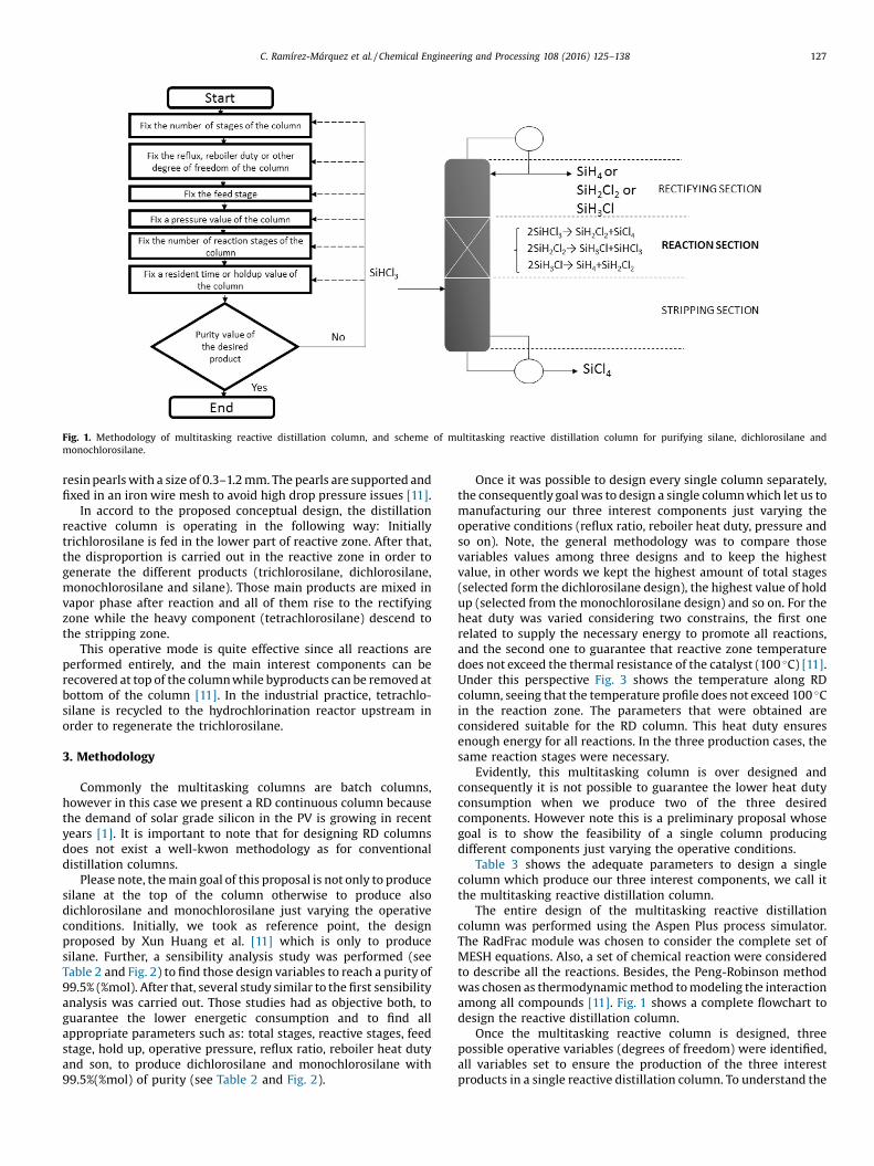
For a catalytic heterogeneous reaction, commonly is included asolid reactive zone in the distillation column where several masstransfer phenomena are carried out. This make possible theintegration among reaction and separation at the same time. Thetypical distillation column is shown in Fig. 1, this columns includesthree zones: rectifying zone, reactive zone and stripping zoneplaced at the high zone, middle zone and inferior zone respectively.The reaction occurs using as catalyst an ionic exchange polymeric
Fig. 1. Methodology of multitasking reactive distillation column, and scheme of multitasking reactive distillation column for purifying silane, dichlorosilane andmonochlorosilane.
C. Ramírez-Márquez et al. / Chemical Engineering and Processing 108 (2016) 125–138 127
resin pearls with a size of 0.3–1.2 mm. The pearls are supported andfixed in an iron wire mesh to avoid high drop pressure issues [11].
In accord to the proposed conceptual design, the distillationreactive column is operating in the following way: Initiallytrichlorosilane is fed in the lower part of reactive zone. After that,the disproportion is carried out in the reactive zone in order togenerate the different products (trichlorosilane, dichlorosilane,monochlorosilane and silane). Those main products are mixed invapor phase after reaction and all of them rise to the rectifyingzone while the heavy component (tetrachlorosilane) descend tothe stripping zone.
This operative mode is quite effective since all reactions areperformed entirely, and the main interest components can berecovered at top of the column while byproducts can be removed atbottom of the column [11]. In the industrial practice, tetrachlo-silane is recycled to the hydrochlorination reactor upstream inorder to regenerate the trichlorosilane.
3. Methodology
Commonly the multitasking columns are batch columns,however in this case we present a RD continuous column becausethe demand of solar grade silicon in the PV is growing in recentyears [1]. It is important to note that for designing RD columnsdoes not exist a well-kwon methodology as for conventionaldistillation columns.
Please note, the main goal of this proposal is not only to producesilane at the top of the column otherwise to produce alsodichlorosilane and monochlorosilane just varying the operativeconditions. Initially, we took as reference point, the designproposed by Xun Huang et al. [11] which is only to producesilane. Further, a sensibility analysis study was performed (seeTable 2 and Fig. 2) to find those design variables to reach a purity of99.5% (%mol). After that, several study similar to the first sensibilityanalysis was carried out. Those studies had as objective both, toguarantee the lower energetic consumption and to find allappropriate parameters such as: total stages, reactive stages, feedstage, hold up, operative pressure, reflux ratio, reboiler heat dutyand son, to produce dichlorosilane and monochlorosilane with99.5%(%mol) of purity (see Table 2 and Fig. 2).
Once it was possible to design every single column separately,the consequently goal was to design a single column which let us tomanufacturing our three interest components just varying theoperative conditions (reflux ratio, reboiler heat duty, pressure andso on). Note, the general methodology was to compare thosevariables values among three designs and to keep the highestvalue, in other words we kept the highest amount of total stages(selected form the dichlorosilane design), the highest value of holdup (selected from the monochlorosilane design) and so on. For theheat duty was varied considering two constrains, the first onerelated to supply the necessary energy to promote all reactions,and the second one to guarantee that reactive zone temperaturedoes not exceed the thermal resistance of the catalyst (100 �C) [11].Under this perspective Fig. 3 shows the temperature along RDcolumn, seeing that the temperature profile does not exceed 100 �Cin the reaction zone. The parameters that were obtained areconsidered suitable for the RD column. This heat duty ensuresenough energy for all reactions. In the three production cases, thesame reaction stages were necessary.
Evidently, this multitasking column is over designed andconsequently it is not possible to guarantee the lower heat dutyconsumption when we produce two of the three desiredcomponents. However note this is a preliminary proposal whosegoal is to show the feasibility of a single column producingdifferent components just varying the operative conditions.
Table 3 shows the adequate parameters to design a singlecolumn which produce our three interest components, we call itthe multitasking reactive distillation column.
The entire design of the multitasking reactive distillationcolumn was performed using the Aspen Plus process simulator.The RadFrac module was chosen to consider the complete set ofMESH equations. Also, a set of chemical reaction were consideredto describe all the reactions. Besides, the Peng-Robinson methodwas chosen as thermodynamic method to modeling the interactionamong all compounds [11]. Fig. 1 shows a complete flowchart todesign the reactive distillation column.
Once the multitasking reactive column is designed, threepossible operative variables (degrees of freedom) were identified,all variables set to ensure the production of the three interestproducts in a single reactive distillation column. To understand the
Table 2Data for the independent design reactive distillation column for the production ofsilane, dichlorosilane and monochlorosilane.
Silane
Stages 62Feed stage 51Condenser TotalConvergence StandardReflux ratio Mole 63Distillate to feed ratio Mole 0.25Pressure 5 atmPressure drop per stage 500 N/sqm
ReactionStart stage Final stage ID Reaction21 42 R-1
HoldupStart stage Final stage Vol [cum]21 42 0.09
DichlorosilaneStages 65Feed stage 51Condenser TotalConvergence StandardReflux ratio Mole 30Distillate to feed ratio Mole 0.50Pressure 1.0 atmPressure drop per stage 500 N/sqm
ReactionStart stage Final stage ID Reaction21 50 R-1
HoldupStart stage Final stage Vol [cum]21 50 0.10
MonochlorosilaneStages 63Feed stage 51Condenser TotalConvergence StandardReflux ratio Mole 68Distillate to feed ratio Mole 0.3335Pressure 1.5 atmPressure drop per stage 500 N/sqm
ReactionStart stage Final stage ID Reaction21 50 R-1
HoldupStart stage Final stage Vol [cum]21 50 0.15
128 C. Ramírez-Márquez et al. / Chemical Engineering and Processing 108 (2016) 125–138
role of those three degrees of freedom, a parametric study wasperformed getting as result that the column pressure does notaffect as much as the other variables, however it was possible tofind a wide range of column pressure values. Furthermore, todelimitate and set a single column pressure value some calculationwas performed, the total annual cost [12], the green-house gasemission [13] and a preliminary qualitative control study such thesingular value decomposition (SVD) respectively.
In order to calculate the total annual cost (TAC), we used themethod published by Guthrie [12]. It performs cost estimation ofan industrial plant separated in units, we carried out a costapproximation of the process using Equation (7), i.e.:
TAC ¼Xn
i¼1CTM;i
nþXnj¼1
Cut;j ð7Þ
Where TAC is the total annual cost, CTM is the capital cost of theplant, n is the total number of individual units and Cut is the cost ofservices, respectively.
To calculate the green-house gas emission, the CO2 producedby combustion in a stoichiometric equation is described asfollow:
CxHy þ x þ y4
� �O2 ! xCO2 þ y
2H2O ð8Þ
where x and y denote the amount of carbon, C, and hydrogen, H,present in the fuel compositions. A complete oxidation of carbon isassumed.
In the combustion of fuels, air is assumed to be in excess toensure complete combustion, so that no carbon monoxide isformed. CO2 emissions (ton/y), are related to the amount of fuelburnt, QFuel (kW), in a heating device is calculated as follow:
½CO2�Emiss ¼QFuel
NHV
� �C%100
� �/ ð9Þ
where a(=3.67) is the ratio of molar masses of CO2 and C, whileNHV (kJ/kg) represents the net heating value of a fuel with a carboncontent of C% (�) [13].
The singular value decomposition technique (SVD) is an open-loop control methodology where the natural dynamic of anyprocess is observed. The initial target is to obtain the open-loopresponse after disturbance of those analyzed process. Theresponses were obtained through the use of Aspen Dynamics.The transfer function matrices (G) were then collected for eachcase, and they were subjected to singular value decomposition(SVD):
G = VSWH (10)
where S = diag (s1,���,sn), si = singular value of G = l1=2i (GGH);
V = (v1, v2, . . . .) matrix of left singular vectors, and W = (w1,w2, . . . .) matrix of right singular vectors. Two parameters ofinterest are the minimum singular value, s*, and the ratiomaximum to minimum singular values, or condition number:
g* = s*/s* (11)
The minimum singular value is a measure of the invertibility ofthe system and represents a measure of potential problems in thesystem under feedback control. The condition number reflects thesensitivity of the system under uncertainties in process parametersand modeling errors. These parameters provide a qualitativeassessment of the theoretical control properties of the alternatedesigns. The systems with higher minimum singular values andlower condition numbers are expected to show the best dynamicperformance under feedback control [14].
Once the TAC, green-house emission and SVD calculation wereperformed, the column pressure was selected such that a goodbalance among economic, environmental and preliminary dynam-ic results was obtained. Then, several comparative studies of thecontrol properties in multitasking reactive column were devel-oped. The control strategies considered are described in the nextsection.
3.1. Setting-up the temperature, composition and cascade controllers
In order to establish if the column can be effectively controlledduring operation is necessary to carry out a control analysis andthree different control methodologies were analyzed: tempera-ture, composition and cascade (control/composition) [15]. Thosethree methodologies were applied to the multitasking reactivedistillation column during the production of each componentensuring the operability of the column.
Fig. 2. Compositions profiles: a) silane, b) monochlorosilane and c) dichlorosilane.
C. Ramírez-Márquez et al. / Chemical Engineering and Processing 108 (2016) 125–138 129
3.1.1. Temperature controllerAll control studies were performed in Aspen Plus Dynamics. In
this case the initial step to design the temperature control is to findthe proper tray where the controller must be placed [15]. Thecontroller location is possible if the analyzed scheme is subject to adisturbance in the manipulated variable. The disturbance willproduce a DT on each stage considering as initial temperaturethese before the disturbance. Once all DT are known, the controlleris set where the biggest DT is located [16].
Once the location of the highest DT is done, a death timemodule followed by a PI controller are placed selecting thetemperature as process variable. The controller action must bespecified as reverse. Moreover, it must be placed a level controlleron each reboiler/condenser, a pressure controller on condenser anda feed controller at entrance of the column (See Fig. 4).
After that, a positive/negative disturbance of 10% in columnfeed is done, later in order to evaluate the effect of impurities in the
feed stream, a disturbance of �5% is applied to the componentobtained as distillate flowrate. Finally, all those controllers aretuned up considering the technique proposed by Tyreus-Luyben[17].
3.1.2. Composition controllerUsing a composition controller usually the measurements has
bigger dead times than temperature controllers [15]. In this case, a3 min delay on composition measurement was considered.
Initially a dead time module followed by a PI controller is set(See Fig. 5). In order to control the distillate and bottoms outputcomposition a structure based on energy balance considerations isused, this structure yields to the called LV control structure, whichuse the reflux flowrate L and the vapor boilup rate V [18]. As initialstep a disturbance of 10% in column feed is done, later in order toevaluate the effect of impurities in the feed stream, a disturbanceof �5% is applied to the component obtained as distillate flowrate.
Fig. 3. Temperature profiles (silane, monochlorosilane and dichlorosilane).
130 C. Ramírez-Márquez et al. / Chemical Engineering and Processing 108 (2016) 125–138
Finally, all those controllers are tuned up considering thetechnique proposed by Tyreus-Luyben [17].
3.1.3. Cascade controlIn the cascade control strategy a composition and temperature
controller are used. The composition controller is considered asprimary, and the temperatures is considered as secondary [15]. Thetemperature controller is placed following the methodologydescribed in temperature controller section, however now thenew set point is the output signal of composition controller (SeeFig. 6).
The temperature controller is tuned up as has been described incomposition controller section. The composition controller isretuned up from its output signal, which is now the newtemperature set point. In this manner the temperature controlis set automatically and the feedback control is carried out in thecomposition controller. All those controllers are tuned upconsidering the methodology proposed by Tyreus-Luyben [17].
Table 3Data for the reactive distillation column for the production of silane, dichlorosilane an
Silane
Stages 65Feed stage 51Condenser TotalConvergence Standard
Design specificationsReflux ratio Mole 63
Distillate to feed ratio Mole 0.25
Pressure 2.3 atm
Pressure dropPressure drop per stage 500 N/sqm
ReactionStart stage Final stage
21 50
HoldupStart stage Final stage
21 50
3.2. Methodology to switch products in the RD column multitasking
A fundamental part of this study is to have a manual operationto switch from one component to other without affecting theircontrol properties.
The control temperature strategy is chosen to perform the shiftin components since this strategy is the simplest one, as it providesdegrees of freedom in the output of the current distillate flow rate.This scenario is quite different than the other two strategies as wellas less equipment is required for industrial operation, in exampleonly two thermocouples in the right position and the controller inthat column are needed. It is also important to note that the changeamong components begins with the conditions to producedichlorosilane, since this variable values are the biggest regardingto distillate flow rate and reboiler heat duty.
The change was made by connecting a multiply between theoutput at top of the column and the feed flow rate, providing theproper distillate to feed ratio to produce each component
d monochlorosilane.
Dichlorosilane Monochlorosilane
30 680.50 0.3335
ID ReactionR-1
Volcum0.15
Fig. 4. Temperature controller scheme.
Fig. 5. Composition controller scheme.
C. Ramírez-Márquez et al. / Chemical Engineering and Processing 108 (2016) 125–138 131
Fig. 6. Cascade controller scheme.
132 C. Ramírez-Márquez et al. / Chemical Engineering and Processing 108 (2016) 125–138
(Distillate to feed = 3 when dichlorosilane pass to monochlorosi-lane and Distillate to feed = 4 when silane pass to monochlor-osilane). Once the multiply is connected, the temperature of thecontrolled tray is varied gradually, until obtain the necessary traytemperature to produce each desired component.
4. Results
According to the methodology section, initially three differentschemes were consider to produce one single interest product in aseparately way. Table 2 shows all variable values such astheoretical stages, reactive stages, reflux ratio, feed stage andcolumn pressure of each design. Please note that in order to designa single RD column to produce the three interest component, somevariables values were kept in the higher obtained values. I.e., thedesign to produce dichlorosilane has the highest amount of stages,so this design is considered as the reference in number of stages. Ithappens the same in hold up values, the biggest value in hold upwas kept to design a single multitasking reactive column (SeeTable 3). The remaining degrees of freedom were used to define theoperating conditions for obtaining each product of interest in thesame column. As described above, the column pressure in amultitasking reactive distillation column would cover an operativewindow wherein the three components can be produced under arange of 1.7 and 2.6 atm. To facilitate the column operation inmultitask mode the pressure column must be adjusted in thesame value for all products. Such selection cannot be done basedonly on the energy requirements but also on their dynamiccharacteristics.
The results obtained from the TAC, green-house emission andSVD calculation will be presented in section 4.1. Note that all those
analysis were very useful to set the operation variables values suchas pressure in the design a single multitasking reactive distillationcolumn which can be able to produce independently silane,monochlorosilane and dichlorosilane.
4.1. Preliminary analysis
It is well known that distillation columns have a high energyconsumption. Under this perspective, energy studies were made toproduce a single interest component. The data suggested thatoperating at 2 atm forwards generate a diminishment in TAC valuesand heat duty consumption when silane and monochlorosilane areproduced.
Other important aspect which must be considered jointly witheconomic aspects is the green-house emissions produced byburning fuel to produce heat enough in a distillation column.Table 4 shows the results of the green-house emissions. It is clearthat the green-house emissions are not determinant to fix thecolumn pressure. However the best values are obtained in a rangeamong 2 and 2.5 atm.
When the SVD analysis is made, despite this analysis wasperformed in a wide pressure range, is quite clear that the columnpressure which produce a better dynamic behavior to producesilane, monochlorosilane and dichlorosilane is 2, 1 and 0.5 atmrespectively. In distillation, pressure is commonly controlled byadjusting the condenser duty, such that the operating pressure alsodefines the size of the heat exchanger and cooling requirements. Inorder to guarantee the proper operation of the multitask column, itshould be fixed in the upper value, obtained for the silaneproduction. In this way, the column pressure could be fixed as2 atm. However, the SVD results showed are not conclusive to fix a
Table 5Operating conditions for multitasking DR column for production of silane, monochlorosilane and dichlorosilane.
C. Ramírez-Márquez et al. / Chemical Engineering and Processing 108 (2016) 125–138 133
single column pressure value since the operative range is located ina range among 0.5 and 4.5 atm.
All the results obtained in section 4.1 leaded us to set thecolumn pressure in an average pressure values, 2.3 atm. Conse-quently only the reflux ratio and reboiler heat duty are left asdegrees of freedom to obtain in a single multitasking reactivecolumn all the desired products. Once the pressure column is set,varying a range of values in reboiler heat duty and reflux ratio waspossible to find some values which may produce all our interestproducts.
Fig. 3 describes the multitasking reactive distillation column.The parameters to design this columns are shown in Table 5, aswell the operation variables to produce each interest componentwith a purity of 99.5% (%mol). The dash cells dash [-] where foundas non-feasible operation points.
4.2. Dynamic simulation
With a fixed pressure column, three control structures(Temperature, composition and cascade strategy) were analyzedseparately and applied to the multitasking reactive distillationcolumn during the production of each component. In all controlstructures the target was to keep the product purity at top in 99.5%(%mol) of silane, monochlorosilane and dichlorosilane. All thosecontrollers are tuned up considering the technique proposed byTyreus-Luyben and the results are showed in Table 6. The results ofeach control tests will be described below.
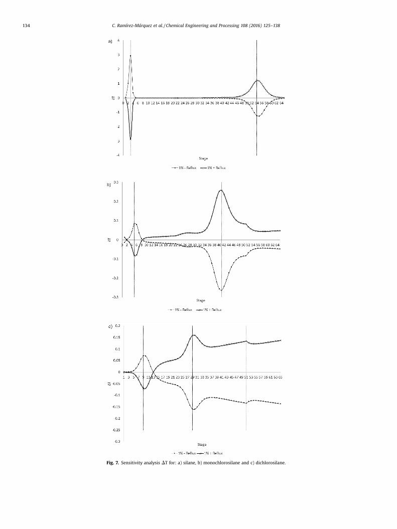
4.2.1. Temperature control schemeIn accord to the methodology section, where the highest DT on
each stage was found, in such stage the controller was located. InFig. 7 the most sensitive stages are shown. In the case of silaneproduction, the controllers was located at stage 3 and 54. Whendichlorosilane was produced the controllers was located at stage 9and 30, and finally for monochlorosilane production the con-trollers was located at stage 5 and 41. Fig. 4 shows the entirecontrol structure.
When a positive/negative disturbance of 10% was applied in thefeed flow stream, the responses obtained are shown in Fig. 8. Fig. 8shows that in despite of those disturbances, the purity in productstream was keep it in the target value. In the case of silane andtetrachlorosilane, the observed settling time was near 5 h in bothcases and the settling time of temperature process was less than5 h in both components. Moreover, Fig. 9 shows the response ofproduct composition after the contamination in feed stream. Notethat after disturbance, the composition returned to its nominalvalue at both top and bottom of the column.
In the case of dichlorosilane production, the temperaturecontrol strategy could keep the purity in the target value afterdisturbance with only a slight offset of 0.0005% mol. The observedsettling time for dichlorosilane was around 4 h. Furthermore, thetetrachlorosilane purity was not affected by disturbance. However,in this case after disturbance, the composition did not return to itsnominal value at the top of the column. At the bottom of thecolumn no changes in purity were observed.
Fig. 7. Sensitivity analysis DT for: a) silane, b) monochlorosilane and c) dichlorosilane.
134 C. Ramírez-Márquez et al. / Chemical Engineering and Processing 108 (2016) 125–138
Fig. 8. Disturbance in feed flow stream (� 10% F) for silane [temperature].
Fig. 9. Composition of feed which has an impurity of silane (SiH4 0.05, 0.95 SiHCl3) [temperature].
C. Ramírez-Márquez et al. / Chemical Engineering and Processing 108 (2016) 125–138 135
When monochlorosilane is produced, the temperature controlstrategy was capable to keep the purity in the target value afterdisturbance. However a similar scenario was observed indichlorosilane production in terms of a little offset of 0.0005%mol. The settling time of monochlorosilane response was near 3 hand the tetrachlorosilane purity was not affected by disturbance. Inthe same way the dichlorosilane feed flow stream was subject tocontamination. However, it was not feasible to return the purity toits nominal value. At the bottom of the column the tetrachlor-osilane purity did not show any change.
Very important to notice that the temperature control strategyresulted to be a feasible alternative to perform a switch amongdesired components since it was possible to stabilize allcomponents temperature.
4.2.2. Composition control schemeAs in temperature control study the multitasking column was
subjected to a positive/negative disturbance of 10% in feed flow
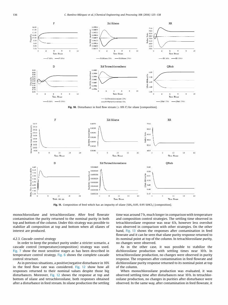
stream. Fig. 10 shows that is totally possible to control both silaneand tetrachlorosilane purities in stream products despite bigdisturbances. The settling time in both cases are around 4 h.However under this strategy a higher overshot in dynamicresponse is observed in comparison with temperature controlstrategy. Moreover, Fig. 11 shows the response of productcomposition after the contamination in feed stream. It is clearthat after disturbance, the composition returned to its nominalvalue at both top and bottom of the column.
Analyzing under this strategy the dichlorosilane production,the dynamic responses after disturbance, in this case the settlingtimes observed were near 2 h. The tetrachlorosilane did not showany change on composition. When the feed flowrate wascontaminated with both components, dichlorosilane and silicontetrachloride returned to its nominal purity values.
Furthermore, when monochlorosilane is produced, this controlstrategy as well as with other components the purity response wascontrolled with settling times near 5 h in both components
Fig. 10. Disturbance in feed flow stream (� 10% F) for silane [composition].
Fig. 11. Composition of feed which has an impurity of silane (SiH4 0.05, 0.95 SiHCl3) [composition].
136 C. Ramírez-Márquez et al. / Chemical Engineering and Processing 108 (2016) 125–138
monochlorosilane and tetrachlorosilane. After feed flowratecontamination the purity returned to the nominal purity in bothtop and bottom of the column. Under this strategy was possible tostabilize all composition at top and bottom when all silanes ofinterest are produced.
4.2.3. Cascade control strategyIn order to keep the product purity under a stricter scenario, a
cascade control (temperature/composition) strategy was used.Fig. 7 show the most sensitive stages as has been described intemperature control strategy. Fig. 6 shows the complete cascadecontrol structure.
As in previous situations, a positive/negative disturbance in 10%in the feed flow rate was considered. Fig. 12 show how allresponses returned to their nominal values despite those bigdisturbances. Moreover, Fig. 12 shows the response at top andbottom of silane and tetrachlorosilane, both responses obtainedafter a disturbance in feed stream. In silane production the settling
time was around 7 h, much longer in comparison with temperatureand composition control strategies. The settling time observed intetrachlorosilane response was near 6 h, however less overshotwas observed in comparison with other strategies. On the otherhand, Fig. 13 shows the responses after contamination in feedflowrate and it can be seen that silane purity response returned toits nominal point at top of the column. In tetrachlorosilane purity,no changes were observed.
As in the other case, it was possible to stabilize thedichlorosilane production with settling times near 10 h. Intetrachlorosilane production, no changes were observed in purityresponse. The responses after contamination in feed flowrate anddichlorosilane purity response returned to its nominal point at topof the column.
When monochlorosilane production was evaluated, it wasobserved settling time after disturbances near 10 h. In tetrachlor-osilane production, no changes in purities after disturbance wereobserved. In the same way, after contamination in feed flowrate, it
Fig. 12. Disturbance in feed flow stream (� 10% F) for silane [cascade].
Fig. 13. Composition of feed which has an impurity of silane (SiH4 0.05, 0.95 SiHCl3) [cascade].
C. Ramírez-Márquez et al. / Chemical Engineering and Processing 108 (2016) 125–138 137
was possible return the composition to its nominal purity value forboth products.
As general analysis, the temperature control strategy resulted tobe the simplest control strategy, which is also the most used inindustry since only thermocouples are required in the columncontrolled. Further, it was possible to control the temperature oneach stage selected.
Despite a good dynamic behavior observed during compositioncontrol strategy, in industrial practice is not a good alternativesince an online chromatograph is required to measure the purity ofeach component. However, it was possible to stabilize thecomposition of each silane of interest.
In cascade control case, the dynamic response and purityregulation was fast enough in comparison with other strategies.Moreover, this strategy showed the advantage of eliminate theoffset among nominal values and responses after disturbances.However, this control strategy is quite complex and consequentlyall degrees of freedom are specified in a more rigorous way, which
is not suitable to switch the production from one silane to theother.
4.3. Switch products in the RD column multitasking
Fig. 14 shows that it is possible to change the production of anycomponent to other in the column and this took place under thestrategy of temperature control. The switch of components wasconsidered under this control strategy since this control structureis the most simple control methodology, beside industrialinstrumentation requires devices relatively easy to operate, andwith good dynamic performance.
We can see that it is possible to switch from one component toanother with the required purity, by variation in temperature andfood/distillate ratio.
It is evident from the temperatures of the stages that there isonly one route by which can carry out the change component:
Fig. 14. Graphic switch of components in the DR column multitasking.
138 C. Ramírez-Márquez et al. / Chemical Engineering and Processing 108 (2016) 125–138
dichlorosilane-monochlorosilane-silane- and silane-monochloro-silane dichlorosilane, closing the cycle. The controller does notsupport such drastic temperature changes, so changes must beapplied gradually.
5. Conclusions
In this study is showed the feasibility to produce threecomponents (silane, dichlorosilane and monochlorosilane) usinga single multitasking reactive distillation column, taking trichlor-osilane as raw material. This column overcomes the traditionalprocess since only one single unit performs the production andpurification instead of two reactors and four distillation columns,also all material recycles are avoided diminishing the energy andequipment requirements. In this single unit all components wereobtained with high purity, having an entire conversion of thetrichlorosilane to silane and so on. This process showed aneconomical advantage in comparison with the conventionalprocess where production and purification are separated oper-ations. In this proposed design, it was possible to switch from aproduct to other changing only the operating variables such ascolumn pressure, reboiler heat duty and reflux ratio. We mustconsider the values of the parameters in the design of themultitasking RD column do not guarantee the lower energy and thelowest operating cost for all products. To ensure it, a rigorousoptimization study is necessary. After several tests the columnpressure was fixed at 2.3 atm since this condition produced thebest transient response for all products. Moreover, three controlstrategies were evaluated and the results obtained suggest that thethree strategies are able to stabilize the process with similardynamic performance. Although more complex control strategieslead to better dynamic responses, the simplest temperaturecontrol strategy, which is widely implemented in industry,guarantees the proper operation of the systems. Moreover usingthis strategy the multitasking scheme remains keeping somedegrees of freedom for the operation of the multitasking column.Furthermore, the temperature controlling strategy was chosen tomake the switch from a product to other because it is simpler sincerequires less expensive equipment and the structure is lesscomplex than the composition and cascade control strategies.
Acknowledgements
Authors acknowledge the financial support provided byCONACYT and Universidad de Guanajuato.
References
[1] P. Woditsch, K. Wolfgang, Solar grade silicon feedstock supply for PV industry,Sol. Energy Mater. Sol. Cells 72 (2002) 11–26.
[2] A.F.B. Braga, S.P. Moreira, P.R. Zampieri, J.M.G. Bacchin, P.R. Mei, New processesfor the production of solar-grade polycrystalline silicon: a review, Sol. EnergyMater. Sol. Cells 92 (2008) 418.
[3] K. Zweibel, J. Mason, V. Fthenakis, Solar grand plan: solar as a solution, SunWind Energy 4 (2008) 112–117.
[4] A. Morales-Acevedo, G. Casados-Cruz, Forecasting the development ofdifferent solar cell technologies, Int. J. Photoenergy (2013) 1–5.
[5] S. Pizzini, M. Acciarri, S. Binetti, From electronic grade to solar grade silicon:chances and challenges in photovoltaics, Phys. Status Sol. A 202 (2005) 2928–2942.
[6] C.J. Bakay, Process for making silane. U.S. Patent 3,968,199, 1976.[7] O.F. Werner, M. Trygve, H. Arve, M. Morten, K. Hallgeir, Production of Silicon
from SiH4 in a Fluidized Bed, Operation and Results, Report Institute forEnergy Technology, Solar Institute 18, Kjeller, Norway, and TelemarkUniversity College, Porsgrunn, Norway, 2013.
[8] M. Jun Jian, C. Shao-Chun, Q. Ke-Qiang, Thermodynamic study on productionof multicrystalline silicon by Siemens process, Chin. J. Inorg. Chem. 23 (5)(2007) 795–801.
[9] D. Müller, G. Ronge, J.P. Schäfer, H.J. Leimkühler, Development and economicevaluation of a reactive distillation process for silane production. Distillationand Adsorption: Integrated Processes, Bayer AG, D-51368 Leverkuse, 11 pages,2002.
[10] N. Sharma, K. Singh, Control of reactive distillation column: a review, Int. J.Chem. React. Eng. 8 (2010) R5.
[12] R. Turton, R.C. Bailie, W.B. Whiting, J.A. Shaeiwitz, Analysis, Synthesis andDesign of Chemical Process, third edition, Prentice Hall, USA, 2009.
[13] Z. Gadalla, P.J. Olujic, M. Jansens, Reducing CO2 emissions and energyconsumption of heat-integrated distillation systems, Environ. Sci. Technol. 39(2005) 6860–6870.
[14] H.S. Papastathopoulou, W.L. Luyben, Control of a binary sidestream distillationcolumn, Ind. Eng. Chem. Res. 30 (1991) 705.