*Corr. Author’s Address: Northeast Electric Power University, Department of Energy and Power Engineering, Jilin 132012, China, [email protected]
Dynamic Characteristics and Stability Prediction of Steam Turbine Rotor Based on Mesh Deformation
Si, H. – Cao, L. – Li, P.Heyong Si* – Lihua Cao – Pan Li
Northeast Electric Power University, Department of Energy and Power Engineering, China
In order to study the steam flow excited vibration caused by the eccentricity of a rotor, three-dimensional rotor whirl motion is simulated based on mesh deformation. The mechanism of steam flow excited vibration and its influence on the dynamic characteristics of the rotor are investigated. The results show that the exciting forces change with the displacement of the rotor’s centre. Rotor dynamic coefficients are nonlinear when the rotor whirls pass the mesh deformation. The rotor dynamic coefficients and effective damping increase with the increase of whirl frequency. When the whirl frequency is 24.41 Hz, the rotor dynamic coefficients are strongly affected by rotational velocity. The maximum fluctuations of average direct stiffness, cross-coupling stiffness, direct damping and cross-coupling damping are 8.1 %, 113.2 %, 45.8 %, and 121.0 %, respectively. Effective damping fluctuates greatly when both whirl and rotational frequency are 24.41 Hz. The direct stiffness, direct damping, and effective damping increase with the increase of pressure ratio, which can improve rotor stability. The pressure fluctuation on the rotor’s surface is a primary reason for steam flow excited vibration. The stability margin of the rotor can be estimated precisely via effective damping.Keywords: steam turbine; labyrinth seal; steam flow excited vibration; rotor dynamic characteristics; mesh deformation; stability
Highlights• The three-dimensional rotor whirl motion was simulated based on the mesh deformation.• The mechanism of steam flow excited vibration and the influence of factors on the dynamic characteristics of the rotor were
investigated.• The stability of the rotor can be predicted precisely through effective damping.
0 INTRODUCTION
With the continuous growth of power demand and the adjustment of industrial energy structures, steam turbines with large capacities are widely used in power generation. Steam flow plays an essential role in rotor stability. The uneven circumferential clearance in a seal caused by the eccentricity of the rotor will lead to the uneven distribution of steam, which easily induces steam flow excited vibration. This is the main reason for the variation of rotor dynamic characteristics and rotor instability. Therefore, the analysis of rotor dynamic characteristics and the stability of the rotor system including steam flow excited vibration are necessary.
In Alford’s analysis of steam flow exciting forces, the uneven force on rotor produced by steam can easily cause the eccentricity of the rotor, which results in circumferential uneven leakage flow and continuously aggravates the whirl motion of rotor [1]. To analyse the mechanism of steam exciting force, many different computational models of seal have been used by scholars [2] to [6]. With the deepening of research, the computational models of seal for steam flow exciting forces are constantly improved [7] and [8]. In recent years, computational fluid dynamics (CFD) has been widely used for
simulations of fluid flow, combustion, and chemical reactions due to its fast and effective computational model. The static eccentricity of a rotor model is calculated with a steady-state solver, in which the rotor only has rotational motion. The results show that the radial and tangential steam flow exciting forces on rotor increase with the increase of eccentricity [9] and [10]. The rotor dynamic coefficients have a nonlinear relationship with the eccentricity. With the increase of positive prewhirl at seal inlet, the cross-coupling stiffness increases gradually from negative to positive, and the rotor system is unstable [11]. However, a proper reverse prewhirl can enhance the rotor stability [12] and [13]. Based on the influences of preswirl and circumferential movement of steam flow on rotor stability, the damping seal proposed by von Pragenau is applied to practice. The seal can reduce circumferential non-uniform distribution of pressure and cross-coupling stiffness, which can enhance the rotor stability [14].
Based on the static eccentricity of the rotor model, the rotor whirl motion relative to rotating coordinate system is put forward. In this model, the stator and rotor have opposite rotational motion at the same time. Ishii et al. simulated the complex turbulent flow field of the seal to verify the validity of the model, and indicated that the accurate flow field near the teeth
Strojniški vestnik - Journal of Mechanical Engineering 66(2020)3, 164-174
165Dynamic Characteristics and Stability Prediction of Steam Turbine Rotor Based on Mesh Deformation
is necessary for evaluating the rotor dynamic forces [15]. Other scholars conducted a comparative analysis of different solvers via this model and indicated that CFX-TASC flow can accurately calculate the rotor dynamic coefficients [16]. Sivakumar Subramanian et al. studied the influence of centrifugal force on the radial exciting force and tangential exciting force. The centrifugal effect at low rotational velocity decreases the radial exciting force, which is more obvious when the pressure ratio increases; the tangential exciting force is almost constant. However, at the condition of high rotational velocity and high-pressure ratio, the radial and tangential exciting forces change sharply with the centrifugal effect [17]. Scholars established the rotor whirl model for gas turbines and calculated the dynamic coefficients in the frequency domain [18]. In addition, the instability in compressors can be linked to the high structural stress, which are associated with flow-induced blade vibrations. The research on the long-blade turbine stage showed that the frequency of separation vortex had a certain influence on the steam flow excited vibration [19]. In the research on rotor nonlinear motion [20], Ma et al. studied the bifurcation of rotor system and found that the bigger seal diameter, the higher bifurcation velocity of rotor system [21].
At present, simplified models are adopted in most of the research in order to reduce the computational time, such as the static eccentricity of the rotor and the rotor whirl motion based on the relative rotating coordinate. However, these models can only show the forces and flow characteristics at a certain position of rotor. The flow field analysis under the condition of rotor whirl is ignored. Furthermore, the result from the simplified dynamic coefficients equation by
duality is not accurate enough. Therefore, based on the structure of the diaphragm seal, the computational fluid dynamics software is applied to establish a three-dimensional rotor whirl model. The mesh deformation is used to simulate the real rotor whirl. The influences of whirl frequency, rotational velocity, whirl radius and pressure ratio on the steam flow excited vibration are considered to solve the rotor dynamic coefficients. At the same time, the rotor stability of steam turbine is analysed. The structure of the paper and the relative contents of sections are shown as Fig. 1.
1 NUMERICAL MODEL AND METHODS
1.1 Computational Model
Taking a second stage diaphragm seal in a high-pressure cylinder of 300 MW steam turbine as an example, the three-dimensional full-cycle rotor whirl model is established. The unstructured grid is generated by ANSYS ICEM, and the unsteady flow field in seal is calculated with a FLUENT pressure solver. The seal model is shown in Fig. 2. The cavity depth, teeth thickness, convex plate height, and seal tip clearance are represented by h, t, l and Cr, respectively. The specific structural parameters are shown in Table 1.
Fig. 2. Schematic diagram of labyrinth seal structure
A single-frequency rotor whirl model is constructed at one whirl velocity, as shown in Fig. 3. Orbit 1 is an example of single-frequency rotor whirl motion. The expression of motion in the forward direction is as follows:Fig. 1. The framework of research and methods
Strojniški vestnik - Journal of Mechanical Engineering 66(2020)3, 164-174
166 Si, H. – Cao, L. – Li, P.
x t e t( ) = − × × + ×( )Ω Ωcos ,θ0 (1)
y t e t( ) = × × + ×( )Ω Ωsin ,θ0 (2)
where e is the whirl radius of the rotor; x t( ) is the velocity of the x direction; y t( ) is the velocity of the y direction; Ω is the whirl velocity; θ0 is the initial angle; t is the time.
Table 1. Structural parameters of labyrinth seal
Name Value unitCavity depth, h 3.2 mmTeeth thickness, t 0.4 mmConvex plate height, l 2.4 mmSeal tip clearance, Cr 1 mmRotor diameter 496.6 mm
Fig. 3. Schematic diagram of whirl motion
The multi-frequency rotor whirl model is obtained from the improvement of single-frequency rotor whirl model, as shown in Fig. 3. Orbit 2 is an example of multi-frequency rotor whirl motion. The expression of the forward direction is as follows:
x t e ti i( ) = − × × + ×( )∑Ω Ωcos ,θ0 (3)
y t e ti i( ) = × × + ×( )∑Ω Ωsin ,θ0 (4)
where i is the whirl velocity which has five values (750, 1500, 2250, 3000, 3750) r/min.
1.2 Mesh Deformation Method
As the boundary profile of the model will be changed by the whirl of rotor, the defined function is compiled with a user-defined function (UDF) to command the motion of boundary, and mesh deformation is used to the computational domain. Thus, the three-dimensional whirl motion of the rotor is achieved. The main structure of UDF is shown in Fig. 4, in which
the control function of the rotor is DEFINE_CG_MOTION.
Fig. 4. Main structure of UDF program
The boundary parameters are derived from the rated operating conditions of the unit. The pressure boundary is applied to the inlet and outlet, the inlet pressure is 10.7 MPa and the inlet temperature is 744.25 K, the outlet pressure is 10.263 MPa and the outlet temperature is 734.25 K. The N-S equation in labyrinth seal flow field is solved by the standard k–ε equation with the SIMPLE algorithm. Because the mesh can be updated and reconstructed, the high quality of the initial mesh and suitable mesh updating are necessary. The initial mesh number under the condition of static eccentricity is shown in Table 2. There is no significant influence on the results when the grid number reaches 5.4 million.
Strojniški vestnik - Journal of Mechanical Engineering 66(2020)3, 164-174
167Dynamic Characteristics and Stability Prediction of Steam Turbine Rotor Based on Mesh Deformation
The remeshing method of grid updating and dimension function are used; the specific parameters are shown in Table 3. The grids at 0 s and 0.002 s are shown in Fig. 5. Taking a grid element as an example, when the rotor is whirling, rotor displacement appears and the node K on rotor surface moves in the x direction. It can be seen from Table 5 that the volume difference of grids between 0 s and 0.002 s is small, so the grids updated by mesh deformation still have high quality.
Fig. 5. Schematic diagram of mesh deformation
Table 4. Comparison of mesh deformation
Grid statistics t = 0 s t= 0.002 sMinimum volume [m3] 3.3922e-13 3.3882e-13Maximum volume [m3] 1.4430e-07 1.6809e-07Total volume [m3] 9.3375e-04 9.3375e-04Minimum face area [m2] 4.2743e-09 4.2743e-09Maximum face area [m2] 8.0990e-05 8.0970e-05
Fig. 6. Variation of forces with time
In order to verify the accuracy of the model, a single-frequency whirl model is simulated at 50 Hz. The steam flow exciting forces in x and y directions is shown in Fig. 6. Compared with the forces of the honeycomb seal in literature [18], they have a very similar variation trend. Therefore, the model established in this paper is reliable.
1.3 Calculation Method of Rotor Dynamic Coefficients
The mathematical relation between the steam flow exciting forces and rotor dynamic coefficients in the labyrinth seal can be represented by the following equation:
F tF t
k kk k
x ty t
c cc
x
y
xx xy
yx yy
xx xy( )
( )
( )
( )
= −
−
yyx yycx ty t
( )
( ), (5)
where Fx(t) and Fy(t) are the component forces in x and y direction, as shown in Fig. 3. kxx and kyy are the direct stiffness, kxy and kyx are the cross-coupling stiffness, cxx and cyy are the direct damping, cxy and cyx are the cross-coupling damping, x(t) and y(t) are the displacements in the x and y directions.
The rotor dynamic coefficients are solved according to the solution in [22]. The matrix in Eq. (5) is performed by Fast Fourier transform to obtain the matrix in Eq. (6) in the frequency domain.
−−
=
+ ++ +
FF
k j c k j ck j c k j c
dd
x
y
xx xx xy xy
yx yx yy yy
xΩ ΩΩ Ω yy
. (6)
In order to distinguish the forward and backward motions, the forward whirl motion and backward whirl motion are defined as a and b, respectively. For each group of whirl motion, there is the following matrix:
− −− −
=
+ ++ +
F FF F
k j c k j ck j c k j c
ax bx
ay by
xx xx xy xy
yx yx yy y
Ω ΩΩ Ω yy
ax bx
ay by
d dd d
. (7)
Therefore, the dynamic coefficients can be expressed in the following equations. The real parts and the imaginary parts in Eqs. (8) to (11) are the rotor dynamic coefficients.
k j cF d F dd d d dxx xxax by bx ay
ax by bx ay+ =
−( ) − −( )−
Ω , (8)
k j cF d F dd d d dxy xyax bx bx ax
ay bx by ax+ =
−( ) − −( )−
Ω , (9)
k j cF d F dd d d dyx yxby ay ay by
ay bx by ax+ =
−( ) − −( )−
Ω , (10)
Strojniški vestnik - Journal of Mechanical Engineering 66(2020)3, 164-174
168 Si, H. – Cao, L. – Li, P.
k j cF d F dd d d dyy yyby ax ay bx
by ax bx ay+ =
−( ) − −( )−
Ω . (11)
2 RESULTS AND ANALYSIS
Based on the multi-frequency whirl model and solution method of dynamic coefficients, the influences of whirl radius, whirl frequency, rotational velocity and pressure ratio on rotor dynamic characteristics have been researched. The quantitative relationship among
them is also studied. Specific calculation parameters are shown in Table 5.
Table 5. Calculation parameters
Name Value unitWhirl frequency 12.5, 25, 37.5, 50, 62.5 HzWhirl radius 0.05, 0.075, 0.10 mmRotational velocity 750, 1500, 3000 r/minPressure ratio 1.04, 1.06, 1.08 -
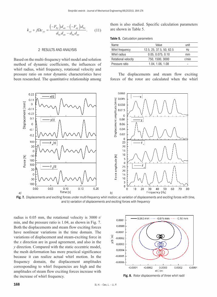
The displacements and steam flow exciting forces of the rotor are calculated when the whirl
a) b) Fig. 7. Displacements and exciting forces under multi-frequency whirl motion; a) variation of displacements and exciting forces with time,
and b) variation of displacements and exciting forces with frequency
Fig. 8. Rotor displacements of three whirl radii
radius is 0.05 mm, the rotational velocity is 3000 r/min, and the pressure ratio is 1.04, as shown in Fig. 7. Both the displacements and steam flow exciting forces have nonlinear variations in the time domain. The variations of displacement and steam-exciting force in the x direction are in good agreement, and also in the y direction. Compared with the static eccentric model, the mesh deformation has more practical significance because it can realize actual whirl motion. In the frequency domain, the displacement amplitudes corresponding to whirl frequencies are high and the amplitudes of steam flow exciting forces increase with the increase of whirl frequency.
Strojniški vestnik - Journal of Mechanical Engineering 66(2020)3, 164-174
169Dynamic Characteristics and Stability Prediction of Steam Turbine Rotor Based on Mesh Deformation
The rotor dynamic coefficients are calculated in three different whirl radiuses. The three whirl orbits are shown in Fig. 8, and the influence of whirl radius on rotor dynamic coefficients is shown in Fig. 9.
It can be seen that the rotor dynamic coefficients present evident nonlinear variation in the multi-frequency whirl motion. With the increase of whirl frequency, the dynamic coefficients present an increasing trend with fluctuation. When the whirl radius grows, the direct stiffness, cross-coupling stiffness, and cross-coupling damping in the xy direction can hardly match themselves in the yx direction. The direct damping increases with the increase of whirl frequency. With the increase of whirl radius, the direct stiffness, cross-coupling stiffness, and cross-coupling damping change obviously but without regularity. Furthermore, they have the approximate trend of trigonometric function under the large whirl radius. Comparing the direct stiffness 0.05 mm with 0.1 mm, it can be determined that the direct stiffness increases with the increase of whirl radius, while the direct damping is less affected by the whirl radius. The duality of dynamic coefficients is used in most studies to simplify the calculation equations, namely, kxx = kyy , cxx = cyy , kxy = –kyx , cxy = –cyx. In
this research, however, the duality is not applicable to the dynamic coefficients except the direct damping. Therefore, in the research of rotor dynamic coefficients for a steam turbine, the results obtained by the simplified equation based on the duality are not accurate enough.
Fig. 10 shows the rotor dynamic coefficients under different rotational velocity. The variation of coefficients is similar to the above analysis, but the rotational velocity also has a great influence on the rotor dynamic coefficients. The dynamic coefficients fluctuate considerably under different rotational velocity when the whirl frequency is near 24.41 Hz. It is shown in Fig. 10 that the rotational velocity has a significant effect on the direct damping in the low-frequency range and this effect decreases gradually with the increase of frequency. The direct damping decreases at exactly 24.41 Hz when the rotational velocity is 1500 r/min. This is because the rotational velocity and whirl velocity are both near the first critical velocity, which makes the stability of rotor decreased. The influence between the rotational velocity and whirl velocity is significantly reduced with the increase of whirl frequency, so the variation of direct damping decreases gradually. The average
Fig. 9. Dynamic coefficients under different whirl radii
Strojniški vestnik - Journal of Mechanical Engineering 66(2020)3, 164-174
170 Si, H. – Cao, L. – Li, P.
Fig. 10. Dynamic coefficients influenced by rotational velocity
Table 6. Fluctuations of average dynamic coefficients at whirl frequency 24.41 Hz
Name Calculation equation
Rotational velocity Maximum fluctuation [%]750 r/min 1500 r/min 3000 r/min
Average direct stiffness [N/m] (kxx + kxx)/2 –250227 –238030 –248539 8.1
direct stiffness, cross-coupling stiffness, direct damping and cross-coupling damping are listed in Table 6, as well as their equations. It can be seen that the rotational velocity of 1500 r/min has the greatest impact on the rotor dynamic coefficients. The maximum fluctuations of average dynamic coefficients are 8.1 %, 113.2 %, 45.8 %, and 121.0 %, respectively.
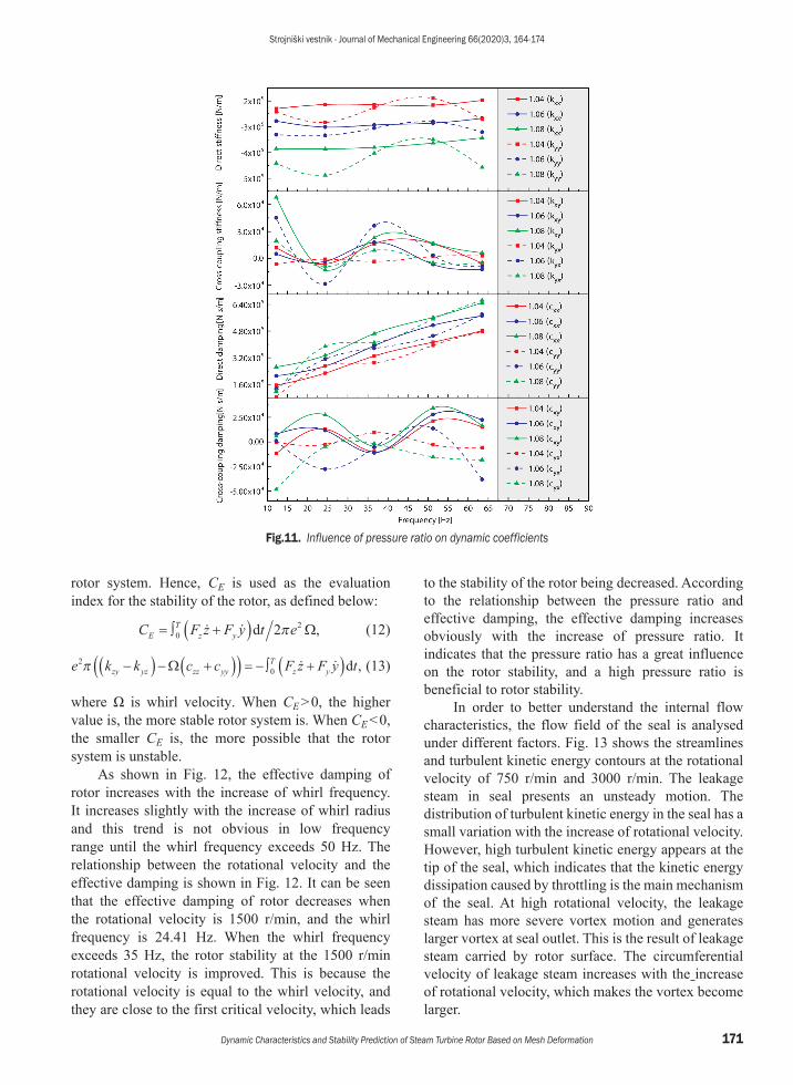
Fig. 11 shows the variation of rotor dynamic coefficients in different pressure ratios between inlet and outlet. The direct stiffness increases gradually towards the negative direction with the increase of pressure ratio, while the direct damping increases towards the positive direction. The direct stiffness and damping vary with pressure ratio in a hierarchical distribution. According to the rotor dynamics analysis,
the increase of direct damping is conducive to the stability of the rotor system and the direct damping increases obviously with the increase of pressure ratio. Therefore, the stability of the rotor system can be improved by increasing the pressure ratio. The variation of cross-coupling stiffness and cross-coupling damping with the increase of pressure ratio is not regular. A comparison of the 1.04 with 1.08 pressure ratio shows that the variation range of cross-coupling stiffness and cross-coupling damping increase as the pressure ratio increases.
The above research shows that the whirl frequency, whirl radius, rotational velocity and pressure ratio have considerable influence on the rotor dynamic coefficients. The effective damping coefficient CE can reflect the stability margin of the
Strojniški vestnik - Journal of Mechanical Engineering 66(2020)3, 164-174
171Dynamic Characteristics and Stability Prediction of Steam Turbine Rotor Based on Mesh Deformation
Fig.11. Influence of pressure ratio on dynamic coefficients
rotor system. Hence, CE is used as the evaluation index for the stability of the rotor, as defined below:
C F z F y t eET
z y= ∫ +( )0
22 d π Ω, (12)
e k k c c F z F y tzy yz zz yyT
z y2
0π −( ) − +( )( ) = − ∫ +( )Ω d , (13)
where Ω is whirl velocity. When CE > 0, the higher value is, the more stable rotor system is. When CE < 0, the smaller CE is, the more possible that the rotor system is unstable.
As shown in Fig. 12, the effective damping of rotor increases with the increase of whirl frequency. It increases slightly with the increase of whirl radius and this trend is not obvious in low frequency range until the whirl frequency exceeds 50 Hz. The relationship between the rotational velocity and the effective damping is shown in Fig. 12. It can be seen that the effective damping of rotor decreases when the rotational velocity is 1500 r/min, and the whirl frequency is 24.41 Hz. When the whirl frequency exceeds 35 Hz, the rotor stability at the 1500 r/min rotational velocity is improved. This is because the rotational velocity is equal to the whirl velocity, and they are close to the first critical velocity, which leads
to the stability of the rotor being decreased. According to the relationship between the pressure ratio and effective damping, the effective damping increases obviously with the increase of pressure ratio. It indicates that the pressure ratio has a great influence on the rotor stability, and a high pressure ratio is beneficial to rotor stability.
In order to better understand the internal flow characteristics, the flow field of the seal is analysed under different factors. Fig. 13 shows the streamlines and turbulent kinetic energy contours at the rotational velocity of 750 r/min and 3000 r/min. The leakage steam in seal presents an unsteady motion. The distribution of turbulent kinetic energy in the seal has a small variation with the increase of rotational velocity. However, high turbulent kinetic energy appears at the tip of the seal, which indicates that the kinetic energy dissipation caused by throttling is the main mechanism of the seal. At high rotational velocity, the leakage steam has more severe vortex motion and generates larger vortex at seal outlet. This is the result of leakage steam carried by rotor surface. The circumferential velocity of leakage steam increases with the increase of rotational velocity, which makes the vortex become larger.
Strojniški vestnik - Journal of Mechanical Engineering 66(2020)3, 164-174
172 Si, H. – Cao, L. – Li, P.
the eccentricity of the rotor, which is caused by the unsteady flow of leakage steam. It is the main reason for steam flow-excited vibration of the rotor. The
Fig. 12. Influence of three factors on effective damping
a) b) Fig. 13. Streamlines and turbulent kinetic energy of flow field; a) rotational velocity is 750 r/min, and b) rotational velocity is 3000 r/min
a) b) Fig. 14. Distribution of pressure on rotor surface; a) pressure ratio is 1.04, and b) pressure ratio is 1.08
Fig. 14 shows the three-dimensional distribution of pressure on the rotor surface. It can be seen that the pressure of rotor surface fluctuates violently as
Strojniški vestnik - Journal of Mechanical Engineering 66(2020)3, 164-174
173Dynamic Characteristics and Stability Prediction of Steam Turbine Rotor Based on Mesh Deformation
maximum pressure fluctuation appears at model inlet and outlet. Compared Fig. 14a and b, the fluctuation range of outlet pressure under the high-pressure ratio is wide, but the pressure distribution is relatively uniform; meanwhile, the lower pressure causes the smaller force on the rotor. At the same time, Fig. 12 shows that the effective damping of the rotor is larger under the high-pressure ratio, so the rotor is relatively stable.
3 CONCLUSIONS AND FUTURE OUTLOOK
The three-dimensional whirl motion is implemented through mesh deformation. On this basis, the influences of whirl radius, whirl frequency, rotational velocity, and pressure ratio on the rotor dynamic characteristics are obtained. The rotor stability affected by steam flow excited vibration is analysed and the mechanism of steam flow excited vibration is clearly revealed through analysis of flow field. The conclusions are as follows.
The rotor whirl motion using mesh deformation is in good agreement with the actual situation. The steam flow exciting forces and dynamic coefficients in multi-frequency whirl motion show nonlinear change and the steam flow exciting forces increase with the increase of whirl frequency. The calculation results obtained from the simplified equation based on duality is not accurate enough.
The whirl radius, whirl frequency, rotational velocity, and pressure ratio have great influence on the rotor dynamic coefficients. The direct damping increases with the increase of whirl frequency. The range of direct stiffness, cross-coupling stiffness and cross-coupling damping are increased at large whirl radius. At the 24.41 Hz whirl frequency, the maximum fluctuations of average direct stiffness, cross-coupling stiffness, direct damping and cross-coupling damping are 8.1 %, 113.2 %, 45.8 % and 121.0 % respectively. The direct stiffness and direct damping increase with the increase of the pressure ratio.
The pressure fluctuation caused by eccentricity is the main reason for steam flow excited vibration. With the increase of rotational velocity, the turbulent kinetic energy increases and the vortex motion is more intense. The effective damping of the rotor can adequately evaluate the rotor stability. The rotor stability increases with the increase of whirl frequency because the effective damping is improved. At a high-pressure ratio, the fluctuation range of pressure at seal outlet is wide, but the pressure distribution is relatively symmetrical and uniform.
The dynamic characteristics and stability of a 300 MW steam turbine rotor influenced by steam flow excited vibration are investigated. The nonlinear dynamic characteristics of the seal are different for steam parameters and seal structures, which is more prominent for the ultra-supercritical units. However, the existing whirl equation is unsuitable for large diameter rotor (over 800 mm). An improved whirl equation for ultra-supercritical units is necessary to make large diameter rotor whirling. Meanwhile, the nonlinear motion of rotor induced by steam flow excited vibration is also worthy of further study.
4 ACKNOWLEDGEMENT
This study was funded by the National Natural Science Foundation of China (NSFC) (grant number 51576036).
5 NOMENCLATURE
e whirl radius of rotor, [m]x t( ) velocity in the x direction, [m/s]y t( ) velocity in the y direction, [m/s]Ω Whirl velocity, [rad/s]ω Rotational velocity, [rad/s]θ0 Initial angle, [rad]t Time, [s]F Steam exciting force, [N]k Stiffness, [N/s]c Damping, [N·s/m]CE Effective damping, [N·s/m]x(t) Displacement in the x direction, [m]y(t) Displacement in the y direction, [m]h Cavity depth, [mm]th Teeth thickness, [mm]T Temperature, [K]l Convex plate height, [mm]Cr Seal tip clearance, [mm]d Displacement in frequency domain, [mm]
Subscripts:x x direction in cartesian coordinates y y direction in cartesian coordinatesi five whirl velocities; (750, 1500, 2250, 3000, 3750) r/minxx from x to x direction in cartesian coordinatesyy from y to y direction in cartesian coordinatesxy from x to y direction in cartesian coordinatesyx from y to x direction in cartesian coordinatesa forward whirl motionb backward whirl motion
Strojniški vestnik - Journal of Mechanical Engineering 66(2020)3, 164-174
174 Si, H. – Cao, L. – Li, P.
5 REFERENCES
[1] Alford, J.S. (1965). Protecting turbomachinery from self-excited rotor whirl. Journal of Engineering for Gas Turbines and Power, vol. 87, no. 4, p. 333-343, DOI:10.1115/1.3678270.
[2] El-Gamal, H.A., Awad, T.H., Saber, E. (1996). Leakage from labyrinth seals under stationary and rotating conditions. Tribology International, vol. 29, no. 4, p. 291-297, DOI:10.1016/0301-679X(95)00043-4.
[3] Kim, H.S., Cho, M., Song, S.J. (2002). Stability analysis of a turbine rotor system with Alford forces. Journal of Sound & Vibration, vol. 258, no. 4, p. 777-790, DOI:10.1006/jsvi.2002.5189.
[4] Ha, T.W., Lee, Y.B., Kim, C.H. (2002). Leakage and rotordynamic analysis of a high pressure floating ring seal in the turbo pump unit of a liquid rocket engine. Tribology International, vol. 35, no. 3, p. 153-161, DOI:10.1016/S0301-679X(01)00110-4.
[5] Vance, J.M., Laudadio, F.J. (1984). Experiment measurement of Alford’s force in axial-flow turbomachinery. Journal of Engineering for Gas Turbines & Power, vol. 106, no. 3, p. 585-590, DOI:10.1115/1.3239610.
[6] Zhang, W.F., Yang, J.G., Tian, Y.W., Cao, h., Gu, J.G. (2013). Research on the leakage and dynamic characteristics of a new kind of radial annular seal and comparisons with labyrinth seals. Proceedings of the Institution of Mechanical Engineers, Part A: Journal of Power and Energy, vol. 227, no. 3, p. 261-271, DOI:10.1177/0957650912474388.
[7] Iwatsubo, T., Ishimaru, H. (2010). Consideration of whirl frequency ratio and effective damping coefficient of seal. Journal of System Design & Dynamics, vol. 4, no. 1, p. 177-188, DOI:10.1299/jsdd.4.177.
[8] Duan, W., Chu, F., Kim, C.H., Lee, Y.B. (2007). A bulk-flow analysis of static and dynamic characteristics of floating ring seals. Tribology International, vol. 40, no.3, p. 470-478, DOI:10.1016/j.triboint.2006.04.010.
[9] Ding, X.J., Yang, Y.L., Chen, W., Huang, H., Zheng, C.G. (2006). Calculation method of efficiency factor in Alford’s force. Proceedings of the Institution of Mechanical Engineers, Part A: Journal of Power and Energy, vol. 220, no. 2, p. 169-177, DOI:10.1243/095765006X75983.
[10] Rhode, D.L., Hensel, S.J., Guidry, M.J. (1993). Three-dimensional computations of rotordynamic force distributions in a labyrinth seal. Tribology Transactions, vol. 36, no. 3, p. 461-469, DOI:10.1080/10402009308983184.
[11] Xia, P., Liu, Z., Yu, X., Zhao, J. (2018). A transient bulk flow model with circular whirl motion for rotordynamic coefficients of annular seals. Chinese Journal of Aeronautics, vol. 31, no. 05, p. 1085-1094, DOI:10.1016/j.cja.2018.02.011.
[12] Tam, L.T., Przekwas, A.J., Muszynska, A., Hendricks, R.C., Braun, M.J., Mullen, R.L. (1987). Numerical and analytical
study of fluid dynamic forces in seals and bearings. Journal of Vibration and Acoustics, vol. 110, no. 3, p. 315-325, DOI:10.1115/1.3269519.
[13] Sun, D., Wang, S., Xiao, Z., Meng, J., Wang, X., Zheng, T. (2015). Measurement versus predictions of rotordynamic coefficients of seal with swirl brakes. Mechanism and Machine Theory, vol. 94, p. 188-199, DOI:10.1016/j.mechmachtheory.2015.08.009.
[14] Li, J., Li, Z.G. (2011). Review of the leakage flow and rotordynamic characteristics of pocket damper seals. Advances in Mechanics, vol. 41, no. 5, p. 519-536, DOI:10.6052/1000-0992-2011-5-lxjzJ2011-028.
[15] Ishii, E., Kato, C., Kikuchi, K., Ueyama, Y. (1997). Prediction of rotordynamic forces in a labyrinth seal based on three-dimensional turbulent flow computation. JSME International Journal. Series C: Mechanical Systems, Machine Elements and Manufacturing, vol. 40, no. 4, p. 743-748, DOI:10.1299/jsmec.40.743.
[16] Hirano, T., Guo, Z., Kirk, R.G. (2003). Application of CFD analysis for rotating machinery: Part 2—Labyrinth seal analysis. ASME Turbo Expo: Power for Land, Sea, and Air, p. 661-667, DOI:10.1115/gt2003-38984.
[17] Subramanian, S., Sekhar, A.S., Prasad, B.V.S.S.S. (2016). Rotordynamic characteristics of rotating labyrinth gas turbine seal with centrifugal growth. Tribology International, vol. 97, p. 349-359, DOI:10.1016/j.triboint.2016.01.003.
[18] Yan, X., Li, J., Feng, Z.P. (2011). Investigations on the rotordynamic characteristics of a hole-pattern seal using transient CFD and periodic circular orbit model. Journal of Vibration & Acoustics, vol. 133, no. 4, p. 783-789, DOI:10.1115/1.4003403.
[19] Zhang, L.Y., He, L., Stüer, H. (2013). A numerical investigation of rotating instability in steam turbine last stage. ASME Journal of Turbomachinery, vol. 135, no. 1, p. 011009, DOI:10.1115/1.4006330.
[20] El-Marhomy, A.A., Abdel-Sattar, N.E. (2004). Stability analysis of rotor-bearing systems via Routh-Hurwitz criterion. Applied Energy, vol. 77, no. 3, p. 287-308, DOI:10.1016/S0306-2619(03)00139-9.
[21] Ma, W., Huang, H., Feng, G., Chen, Z., Kirk, R.G. (2015). Labyrinth seals diameter and length effect study on nonlinear dynamics. Procedia Engineering, vol. 99, p. 1358-1364, DOI:10.1016/j.proeng.2014.12.670.
[22] Li, Z.G., Li, J., Feng, Z.P. (2015). Comparisons of rotordynamic characteristics predictions for annular gas seals using the transient computational fluid dynamic method based on different single-frequency and multifrequency rotor whirling models. Journal of Tribology, vol. 138, p. 011701, DOI:10.1115/1.4030807.