Page 1
Jordan Journal of Civil Engineering, Volume 14, No. 3, 2020
‐ 331 - © 2020 JUST. All Rights Reserved
Received on 4/2/2020. Accepted for Publication on 19/5/2020.
Dynamic Characteristics of Transmission Tower-Line Coupled System
Considering Torsional Effect
Ying Zhou 1), Shuguo Liang 1) and Lianghao Zou 1),2)*
1) School of Civil Engineering and Structure, Wuhan University, China. E-Mail: [email protected] 2) School of Urban Construction, Wuhan University of Science and Technology, China.
E-Mail: [email protected] * Correspondence Author: [email protected]
ABSTRACT
The multi-particle model is a common method for calculating the dynamic characteristics of typical
transmission tower-line coupled systems. The existing multi-particle model often ignores the torsional effect
of the transmission tower when performing tower-line coupling. In order to increase the accuracy of the
calculation results of dynamic property, for the first time, the torsional effect of the transmission tower is
incorporated into the traditional multi-particle model by increasing the degree of freedom of the transmission
tower-line system in theoretical formulae. The developed formulae were then used to analyze the inherent
frequencies of transmission towers and tower-line coupled systems of a typical tower-line structure. The
theoretical calculation results are rather similar to the three-dimensional finite element analysis results and to
the experimental results regarding translational motion frequency and torsional frequency. The research results
could have civil engineering application value for multi-particle model theoretical research and seismic analysis
of vibration characteristics of transmission tower-line systems.
KEYWORDS: Transmission tower-line system, Multi-particle model, Dynamic characteristics, Seismic resistance, Torsion.
INTRODUCTION
High-voltage transmission mode and superhigh-
voltage transmission mode are the main modes of
electric power supply that are most commonly used all
over the world today. According to the statistics of the
American Energy Information Administration (EIA),
there were 307,000 kilometers of high-voltage
transmission lines of 200 kV or more in the United
States of America by the end of 2012. In comparison,
China had a total length of 20,518 kilometers of ultra-
high voltage transmission lines by the end of 2017 with
an annual growth rate of more than 5% (Kunjie, 2028).
The high-voltage transmission tower-line system is a
carrier for high-load power transmission, consisting of a
steel lattice tower body used to support large-span
transmission lines. This coupled system is not only
sensitive to environmental loads, such as earthquakes
and strong winds, but also prone to dynamic fatigue and
instability (Gobarah et al., 1996). In 1995, 38 high-
voltage lines and 446 distribution lines were damaged in
the Hyogo Prefecture Hanshin earthquake (Chen and
Zheng, 2010; Qifeng, 1997). Similarly, in 2006, a 5.1
magnitude earthquake in Yanjin County, Zhaotong City,
Yunnan Province, China, resulted in damaged wires and
collapse of various transmission towers within the 119.2
km transmission network and therefore caused severe
economic losses (Meigen Cao et al., 2007).
The evaluation of dynamic characteristics of the
transmission tower-line system by determining the inherent
frequency and vibration mode of the system is a
fundamental part of the structural wind-resistant and
seismic design (Irvine, 1981; Danesh, 2019; Shatnawi and
Al-Qaryouti, 2018). The mutual coupling effect in the
transmission tower-line system makes it a very
complicated coupled system and therefore it is quite
difficult to accurately evaluate the system‘s dynamic
characteristics subjected to multi-component seismic
excitations. The influence of the transmission line on the
Page 2
Dynamic Characteristics of… Ying Zhou, Shuguo Liang and Lianghao Zou
- 332 -
dynamic characteristics of the transmission tower (Irvine,
1981; Ozono et al., 1988; Ozono and Maeda, 1992) shows
the mass effect which tends to reduce the natural frequency
of the transmission tower, the stiffness effect which
changes the global stiffness matrix of the system and the
energy dissipation effect which causes a considerable
increase in the damping of the transmission tower.
Researchers generally investigate the dynamic
characteristics of transmission tower-line systems
through finite element analysis (FEA) model,
mechanical model and dynamic test. The FEA model
can couple the transmission tower with the transmission
line with considerations of six degrees of freedom, but
the complicated FEA process and analysis could build a
barrier for its engineering application for practical
purposes. Also, it is still necessary to comprehensively
analyze the measured data from the field (e.g., shaking
table test) and the wind tunnel tests for broad
understanding (Chunxiang et al., 2009). The limited size
of the existing seismic simulation shaking table and the
large span of transmission tower-line structure make it
impractical to carry out the test on a shaking table. Wind
tunnel tests are even more complicated, especially in
model design and flow field simulation (Huijun Yin and
Weilian Zhai, 2002).
In terms of the mechanical model for the calculation
of the dynamic characteristics of the transmission tower-
line system, Irvine (1981) proposed a continuum model
for calculating static and dynamic characteristics of
cable structures. However, the coupling effect in the
tower-line system was ignored for the sake of simplicity.
Li and his co-authors (Xianxin Wang and Hongnan Li,
1989; Hongnan Li and Xianxin Wang, 1990 and Li,
1999) believed that the long-span transmission system
should consider the interaction between the wire and the
transmission tower for analyzing the dynamic
characteristics of the transmission tower system by
using the energy principle theory. A simplified multi-
particle model was proposed, the results of which
showed that the vibration frequency of the transmission
tower system is reduced due to the influence of the wire.
Afterwards, Liang and Ma, as well as Liang et al. (2003)
proposed a multi-degree-of-freedom calculation method
based on the simplified multi-particle model. The
influence of the vibration coupling of the tower-line
system on the natural frequency and vibration mode of
the tower line was analyzed. The results showed that the
mass ratio between the wire and the tower has a minor
influence on the natural frequency of the transmission
tower system.
The above mentioned multi-particle model is a
widely used mechanical alalysis model that can reflect
the tower-line coupled vibration effect of transmission
lines (Liang et al., 2015). The velocity of each mass
point of the coupled system can be obtained directly by
the speed superposition treatment. The increase of the
degree of freedom of the coupled system, however, is
ignored in this coupling method. The result leads to the
decrease of accuracy in the velocity calculation of each
mass point of the coupled system. It is, therefore,
reasonable to couple the transmission tower-line system
for increasing the degree of freedom. Also, the
traditional coupling method simplifies the transmission
tower into a cantilever bar, whereby the torsional effect
of the large-scale cross-arm in the upper part of the
transmission tower is ignored. The translational effect of
the transmission tower is considered only through the
speed superposition. Currently, there are only few
research studies that have been carried out on the
torsional response of transmission towers. The main
reason is that the cross-arm cantilever length of the
tower type studied in the past is small and the torsional
effect is insignificant or even negligible (Xia, 2013).
However, with the improvement of wire transmission
capacity, application of long-cantilever transmission
towers has become extensive. The torsion effect on the
dynamic response of transmission tower-line system
may be more significant, as it could generate a larger
error when calculating the dynamic characteristics of the
tower-line system.
Based on the multi-particle model, this paper
proposed an improved coupling method of the
transmission tower-line system by considering the
torsion effect on the dynamic characteristics of a
representative tower-line structure. The multi-particle
model results were then compared to the FEA results
and the experimental results regarding the vibration
characteristics of the transmission tower line system. As
the developed multi-particle model was verified by the
experimental results, our research results could provide
insight into the accurate theoretical understanding of the
multi-particle model of transmission tower-line coupled
system. As a result, the seismic design of long cantilever
transmission towers could also be improved.
Page 3
Jordan Journal of Civil Engineering, Volume 14, No. 3, 2020
- 333 -
Improvement of Coupling between Transmission
Tower and Wire Firstly, by combining the traditional multi-particle
model theory and the Lagrangian equation (Ghobarah et
al., 1996), the basic differential equation of the
longitudinal vibration of the transmission line is derived.
The calculation methods of the mass matrix and the
stiffness matrix of the wire’s longitudinal vibration are
given. The differences of vibration characteristics of the
tower with and without wire are obtained. Then, by
adding the degree of freedom, the tower-line coupled
method is derived considering the torsional effect of the
upper part of the transmission tower. Subsequently, the
fundamental equation of the longitudinal vibration of the
coupled system is obtained. Finally, the method for
solving the vibration characteristics of the coupled
system is formulated. The following literature only
describes the deduction of the coupling method of the
transmission tower-line system in the plane vibration,
because the coupled mode of the plane vibration is
similar to that.
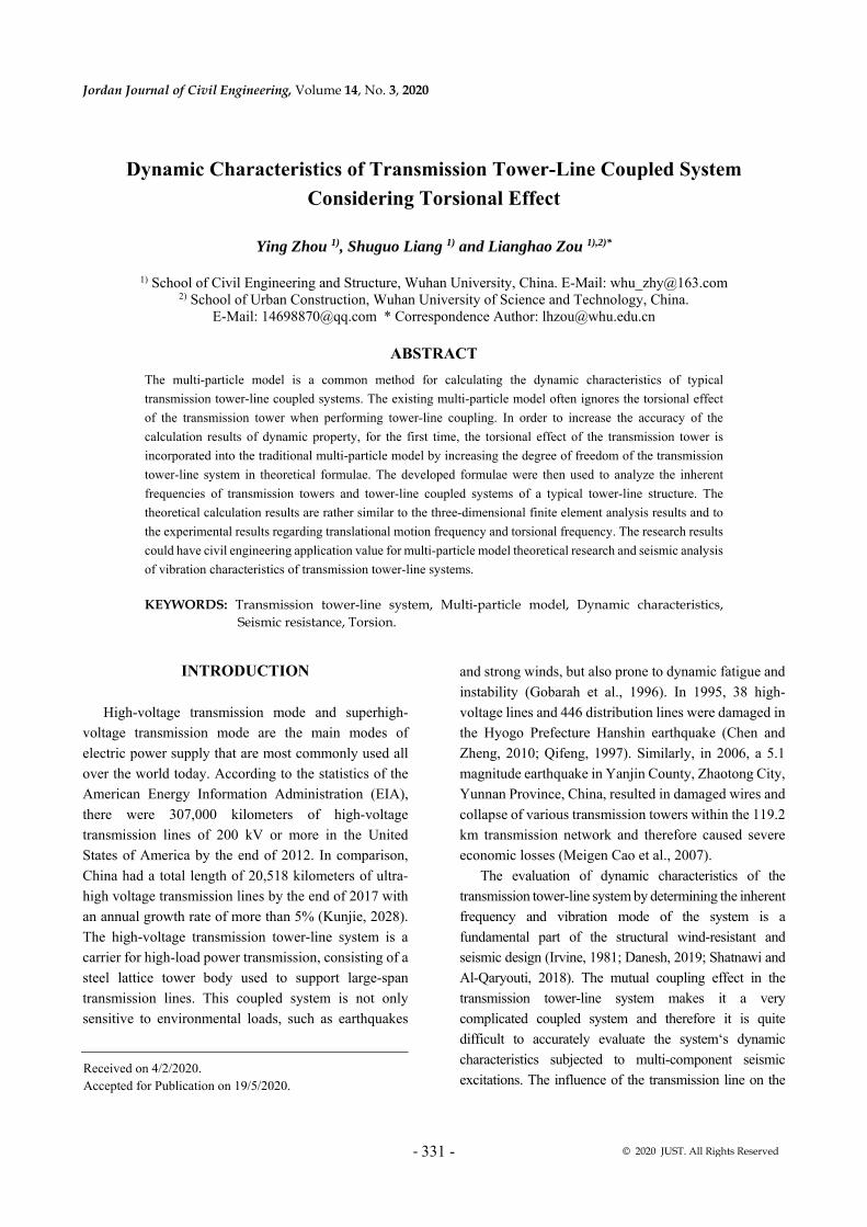
Multi-particle Model Firstly, the longitudinal vibration characteristics of
the transmission line are studied in this section.
According to the multi-particle model, the transmission
line is simplified to a fixed suspension structure at both
ends. Within this structure, multiple degrees of freedom
are composed of the deformable connecting rods and
concentrated particles. As shown in Figure 1, 𝑙 indicates
the length of 𝑖 connecting rod when the suspension
cables are vibrating and 𝑚 indicates the lumped mass.
𝜃 indicates the horizontal angle of the connecting rod
during the vibration of the suspension cables. 𝑆 is the
horizontal length of the connecting rod when the cable
is stationary.
Figure (1): Logitudinal plane vibration of the transmission line with multiple degree of freedom system
Constraints By considering the tensile stiffness of the cable, the
connecting rods should satisfy the geometric
relationship when the cable is stationary.
𝑆 𝑙 𝑙 𝑐𝑜𝑠𝜃𝐻 𝑙 𝑙 𝑠𝑖𝑛𝜃
(1)
where 𝑙 is the original length of the connecting rod;
𝑙 is the static elongation of the connecting rod caused
by the lumped mass when the suspension cable is
stationary; 𝜃 is the horizontal angle of the connecting
rod when the suspension cable is stationary; 𝐻 is the
vertical length of the connecting rod when the cable is
stationary. 𝑺 is the horizontal length of the connecting
rod when the cable is stationary.
We reasonably assume that the angle 𝜃 is positive in
the clockwise direction, the elongation of the connecting
rod is positive and the cable during vibration would
satisfy the following equation.
∑ 𝑙 𝑐𝑜𝑠𝜃 𝐿∑ 𝑙 𝑠𝑖𝑛𝜃 0
(2)
where 𝐿 is the span of the transmission line; 𝑛 is the
number of links.
Vibration Differential Equation For the transmission line with 𝑛 connecting rods and
𝑛 1 particle hinges, the system freedom is 2𝑛 2 .
Page 4
Dynamic Characteristics of… Ying Zhou, Shuguo Liang and Lianghao Zou
- 334 -
After the system is disturbed, it vibrates near the static
equilibrium position. We would combine 𝜉 𝜃 𝜃 ,
𝛿 𝑙 𝑙 𝑙 , 𝜉 and 𝛿 for generalized coordinates
of the system’s vibrational differential equations.
Therefore, 𝜉 and 𝜉 can be expressed as:
𝜉 ∑ 𝜉 ∑ 𝛿
𝜉 ∑ 𝜉 ∑ 𝛿 (3)
where , , and satisfy:
⎩⎪⎪⎪⎨
⎪⎪⎪⎧
𝜕𝜃𝜕𝜃
𝑙 𝑐𝑜𝑠𝜃 𝑙 𝑠𝑖𝑛𝜃 𝑙 𝑠𝑖𝑛𝜃 𝑙 𝑐𝑜𝑠𝜃𝑙 𝑐𝑜𝑠𝜃 𝑙 𝑠𝑖𝑛𝜃 𝑙 𝑠𝑖𝑛𝜃 𝑙 𝑐𝑜𝑠𝜃
𝜕𝜃𝜕𝜃
𝑙 𝑠𝑖𝑛𝜃 𝑙 𝑐𝑜𝑠𝜃 𝑙 𝑐𝑜𝑠𝜃 𝑙 𝑠𝑖𝑛𝜃𝑙 𝑠𝑖𝑛𝜃 𝑙 𝑐𝑜𝑠𝜃 𝑙 𝑐𝑜𝑠𝜃 𝑙 𝑠𝑖𝑛𝜃
𝜕𝜃𝜕𝑙
𝑐𝑜𝑠𝜃 𝑐𝑜𝑠𝜃 𝑠𝑖𝑛𝜃 𝑠𝑖𝑛𝜃𝑙 𝑠𝑖𝑛𝜃 𝑐𝑜𝑠𝜃 𝑐𝑜𝑠𝜃 𝑠𝑖𝑛𝜃
𝜕𝜃𝜕𝑙
𝑐𝑜𝑠𝜃 𝑐𝑜𝑠𝜃 𝑠𝑖𝑛𝜃 𝑠𝑖𝑛𝜃𝑙 𝑠𝑖𝑛𝜃 𝑐𝑜𝑠𝜃 𝑐𝑜𝑠𝜃 𝑠𝑖𝑛𝜃
(4)
The system vibration differential equation is
established by the Lagrange equation (Ghobarah et al.,
1996), excluding the higher-order infinitesimal and
therefore the velocity of each particle in the horizontal
direction is:
⎩⎪⎨
⎪⎧
𝑢 𝐻 𝜉 𝑐𝑜𝑠𝜃 𝛿𝑙
𝑢 𝐻 𝜉 𝑐𝑜𝑠𝜃 𝛿𝑙
𝑗 1,2, … , 𝑖𝑛𝑡 𝑛/2 (5)
The vertical velocity of each particle is:
⎩⎪⎨
⎪⎧
𝑣 𝑆𝜉 𝑠𝑖𝑛𝜃 𝛿𝑙
𝑣 𝑆𝜉 𝑠𝑖𝑛𝜃 𝛿𝑙
𝑗 1,2, … , 𝑖𝑛𝑡 𝑛/2 (6)
where int (*) in Equations (5) and (6) represents a
step function.
Solution of Plane Vibration Characteristics of the
Transmission Line System kinetic energy 𝑇 of the transmission line is:
𝑇12
𝑚 𝑢 𝑣 𝑇 𝜉 , 𝛿𝑙 (7)
Excluding the infinitesimal that is not less than
second-order, the potential energy of the transmission
line 𝑈 is:
𝑈 𝑚 𝑔 𝑙 𝑙 𝛿𝑙 𝑠𝑖𝑛𝜃
𝐸𝐴2𝑙
𝑙 𝛿𝑙 (8)
The system kinetic energy of the transmission line
constitutes the mass matrix of the first-order partial
derivatives of the degrees, whereas the system potential
energy constitutes the stiffness matrix of the first-order
partial derivatives of the degrees. The eigenvalues and
eigenvectors of the system mass matrix and the stiffness
matrix were then solved to obtain the frequency of
vibration mode and vibration mode of the transmission
line at different orders.
If the influence of the tensile stiffness of the wire on
the dynamic characteristics of the wire is not considered,
the simplified multi-particle model only needs to take
𝜉 , 𝜉 , ⋯ , 𝜉 as the generalized coordinates of the
system. The degree of freedom of the simplified model
Page 5
Jordan Journal of Civil Engineering, Volume 14, No. 3, 2020
- 335 -
is reduced. Equation (3) is changed accordingly and the rest of the calculation process is unchanged.
Transmission Tower-line System Coupling
Figure (2): A multi-particle model of a tower and a two-line transmission tower-line system
Traditional Coupling Method for Multi-particle Model When the tower-line coupled system is calculated in
the traditional multi-particle model, the stiffness matrix
is uncoupled, whereas the mass matrix is coupled. As
shown in Figure 2, for a typical one-tower and two-line
multi-particle model, the particles connected to the
tower and the wire move together with the tower.
According to the symmetry, the speed of corresponding
nodes is transmitted by each mass point of the wires near
the tower part. The vertical speed of the wire is constant
and the horizontal speed can be expressed as:
⎩⎪⎨
⎪⎧
𝑢 𝑢 𝐻 𝜉 𝑐𝑜𝑠𝜃 𝛿𝑙
𝑢 𝑢 𝐻 𝜉 𝑐𝑜𝑠𝜃 𝛿𝑙
𝑗 1,2, … , 𝑖𝑛𝑡 𝑛/2 (9)
Comparing Equation (9) to Equation (5), the
coupling method of the traditional multi-particle model
is to superimpose the speed of the corresponding points
of the transmission tower directly on the speed of the
original transmission line. The change in vibration mode
or speed caused by the increase in the degree of freedom
of the system after coupling is not considered.
Further, the kinetic energy of the wire in the
transmission tower-line coupled system is:
𝑇12
𝑚 𝑢 𝑣12
𝑚 𝑢 𝑣12
𝑚 𝑢 𝑗 1,2, … , 𝑖𝑛𝑡 𝑛/2 (10)
After obtaining the kinetic energy of the conductors
in the coupled system, partial derivatives of the wire
free-degrees are taken to obtain the coupling term of the
mass matrix. Then, the transmission tower, the
transmission conductor mass matrix and the stiffness
matrix are combined into a global mass matrix and a
global stiffness matrix. Finally, vibration mode and
frequency of the overall system are obtained after the
eigenvalues and eigenvectors are calculated.
Improvement of Multi-particle Model Coupling
Method
The above analysis shows that the movement of the
transmission tower would cause an overall translation of
the transmission line, which in turn would increase the
translational freedom of the system. In addition, the
torsional effect of the large-scale cross-arm in the upper
Page 6
Dynamic Characteristics of… Ying Zhou, Shuguo Liang and Lianghao Zou
- 336 -
part of the transmission tower also causes a change in
the velocity of each point of the wire. Therefore, when
performing the wire stiffness matrix and the mass matrix
calculation, two degrees of freedom can be added. The
vibration differential equations for the mass points of the
coupled system transmission line can be established
based on the one-column and two-line multi-particle
model in Figure 2 by adding the two degrees of freedom
derived in Equation (3) as:
⎩⎨
⎧𝜉𝜕𝜃𝜕𝜃
𝜉𝜕𝜃𝜕𝑙
𝛿𝜕𝜃𝜕𝜃
𝜃𝜕𝜃𝜕𝑢
𝑢
𝜉𝜕𝜃𝜕𝜃
𝜉𝜕𝜃𝜕𝑙
𝛿𝜕𝜃𝜕𝜃
𝜃𝜕𝜃𝜕𝑢
𝑢 (11)
where 𝑢 is the horizontal displacement of point A
on the transmission tower, 𝜃 is the upper twist angle of
the transmission tower and it satisfies:
⎩⎪⎪⎨
⎪⎪⎧
𝜕𝜃𝜕𝜃
𝑙 𝑐𝑜𝑠𝜃 sin 𝜃 𝜃𝑙
𝜕𝜃𝜕𝜃
𝑙 𝑐𝑜𝑠𝜃 sin 𝜃 𝜃𝑙
𝜕𝜃𝜕𝑢
𝑐𝑜𝑠𝜃 sin 𝜃 𝜃𝑙
𝜕𝜃𝜕𝑢
𝑐𝑜𝑠𝜃 sin 𝜃 𝜃𝑙
(12)
, , and are calculated according to
Equation (4).
The system vibration differential equation is
established by the Lagrange equation, whereas the
horizontal velocity and vertical velocity of each mass
point of the system are calculated according to
Equations (5) and (6), respectively. The kinetic energy
and potential energy of coupled system wires are
respectively obtained according to Equations (7) and
(8). The coupling terms of the mass matrix and the
stiffness matrix of the system can be obtained by
deriving the respective degrees. Then, the mass matrix
and the stiffness matrix for the transmission tower and
the transmission line are combined into an overall mass
matrix and an overall stiffness matrix. The vibration
mode and frequency of the overall system are obtained
by calculating the eigenvalues and eigenvectors.
The coupling of the traditional multi-particle model
keeps the system degrees of freedom constant and only
changes the kinetic energy of the wire by superimposing
the translational velocity of the corresponding particle
on the speed of the transmission tower. Our new
coupling method increases the degrees of freedom of the
coupled system. Starting from the vibration differential
equation of the system, the influence of the transmission
tower translational motion frequency and the upper
torsion can be simultaneously considered. Thus, the
coupled dynamic characteristics of the system can be
better reflected compared to the traditional multi-
particle model.
RESULTS
Engineering Background
In order to demonstrate the accuracy of the improved
multi-particle model coupling method, we selected a
typical power transmission project as a prototype for
analysis. The transmission tower model is ZBV63-75
with a tower height of 80.5m and a span of 750m. The
structural members of the transmission tower are made
of angle steel, whereas the connection forms of the
components are bolted and welded. The main profiles
are shown in Table 1. The transmission line uses four
split wires and the relevant parameters are shown in
Table 2. In order to simplify the calculations the actual
four-split wire is assumed into a single wire whereas the
single wire, density and cross-sectional area are
considered equivalent to those of the four-split wire.
Page 7
Jordan Journal of Civil Engineering, Volume 14, No. 3, 2020
- 337 -
Table 1. Main component profiles of transmission towers
Numbering Lever
specification Profile use position Numbering
Lever
specification Profile use position
1 L200×16 Tower main column
within 28m 6 L140×10 Cross-arm main material
2 L180×16
Tower main column
in the range of
28~34.6m
7 L125×10
Cross-arm main material,
tower main column, tower
body bracing
3 L180×14
Tower main column
in the range of
34.6~45.9m
8 L125×8 Tower body bracing
4 L160×14
Tower main column
in the range of
45.9~60.8m
9 L110×10 Tower head material
5 L140×12
Main column of
tower head above
60.8m
10 L110×8
Tower body bracing,
tower head auxiliary
column
Table 2. Parameters of transmission line material
Span / m 750 Average wire running tension / N 36869
Ground line density / (kg / km) 570.3 Wire cross-sectional area / mm 2 666.55
Wire density / (kg / m) 2060 Ground cross section / mm 2 121.21
Ground sag / m 10.22 Wire elastic modulus / GPa 63
Wire sag / m 38.5 Ground linear modulus / GPa 103
Ground line average running tension / N 38431
Multi-particle Model Analysis Based on the multi-particle model, the dynamic
coupling characteristics of the transmission tower-line
coupled system are calculated by the improved coupling
method. The multi-particle model of the coupled system
is shown in Figure 3.
Figure (3): Transmission tower-line system multi-particle model
Page 8
Dynamic Characteristics of… Ying Zhou, Shuguo Liang and Lianghao Zou
- 338 -
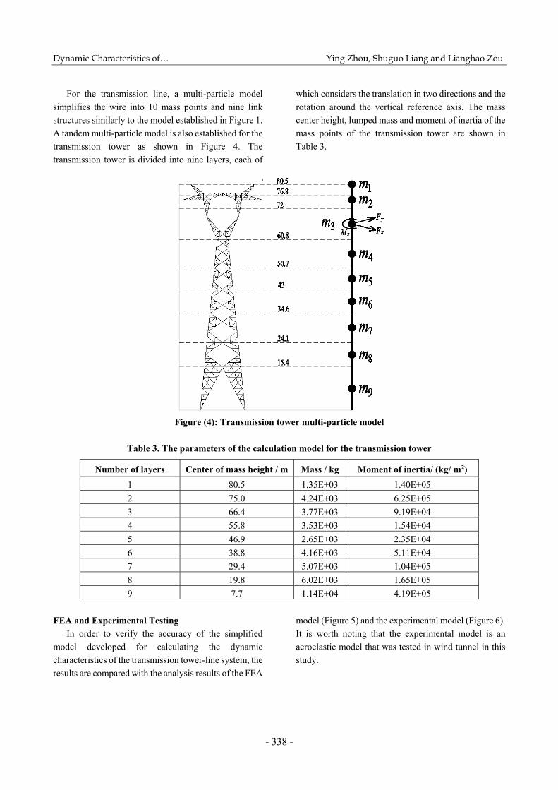
For the transmission line, a multi-particle model
simplifies the wire into 10 mass points and nine link
structures similarly to the model established in Figure 1.
A tandem multi-particle model is also established for the
transmission tower as shown in Figure 4. The
transmission tower is divided into nine layers, each of
which considers the translation in two directions and the
rotation around the vertical reference axis. The mass
center height, lumped mass and moment of inertia of the
mass points of the transmission tower are shown in
Table 3.
Figure (4): Transmission tower multi-particle model
Table 3. The parameters of the calculation model for the transmission tower
Number of layers Center of mass height / m Mass / kg Moment of inertia/ (kg/ m2)
1 80.5 1.35E+03 1.40E+05
2 75.0 4.24E+03 6.25E+05
3 66.4 3.77E+03 9.19E+04
4 55.8 3.53E+03 1.54E+04
5 46.9 2.65E+03 2.35E+04
6 38.8 4.16E+03 5.11E+04
7 29.4 5.07E+03 1.04E+05
8 19.8 6.02E+03 1.65E+05
9 7.7 1.14E+04 4.19E+05
FEA and Experimental Testing
In order to verify the accuracy of the simplified
model developed for calculating the dynamic
characteristics of the transmission tower-line system, the
results are compared with the analysis results of the FEA
model (Figure 5) and the experimental model (Figure 6).
It is worth noting that the experimental model is an
aeroelastic model that was tested in wind tunnel in this
study.
Page 9
Jordan Journal of Civil Engineering, Volume 14, No. 3, 2020
- 339 -
Figure (5): FEA model of transmission tower line system
(a) (b)
Figure (6): The experimental model of (a) transmission tower and (b) tower-line system (photograph)
The finite element model of transmission tower-line
system with six degrees-of-freedom is established by
ANSYS. The tower adopts BEAM188 rod elements,
whereas the transmission line adopts link10 unit. The
insulator is replaced by a rigid rod. The most end line
node applies UX, UY, UZ constraint. Through the
sensitivity analysis of the unit size to the local stress, the
model uses a small unit. The material parameters are
shown in Table 2. Based on the FEA model of the
transmission tower-line system, the dynamic
characteristics of the coupled system after the
transmission line is connected are calculated. In order to
show the effect of the tower line coupling on the results
of dynamic characteristics, we also analyzed and
compared the transmission characteristics of the
transmission tower without hanging the line.
To ensure that the experimental model has a good
real structure representation and that it can be properly
tested in wind tunnel, a similarity theory was used to
scale the structure and wind flow. The similarity scale
ratios for the length, wind speed, frequency, Young’s
modulus and mass are presented in Table 4. It is worth
noting that the experimental work of this project is rather
expensive and only the first vibration model results
Page 10
Dynamic Characteristics of… Ying Zhou, Shuguo Liang and Lianghao Zou
- 340 -
could be measured in this study. Figure 7 shows the free
vibration deformations of the tower-line system in X and
Y directions.
Table 4. The scale ratios for different parameters
Parameter Length L Wind speed U Frequency n Young’s modulus EA Mass m
Scale equation n n0.5 n-0.5 n3 n3
Scale ratio 1:40 1:6.32 6.32:1 1:64000 1:64000
0.0 0.2 0.4 0.6 0.8 1
-1.8
-1.2
-0.6
0.0
0.6
1.2
1.8
2.4
disp./mm
t/s0.0 0.2 0.4 0.6 0.8
-3
-2
-1
0
1
2di
sp./
mm
t/s
(a) (b)
Figure (7): The free vibration deformations oft he tower-line system in (a) X direction and (b) Y direction
Calculation Results and Discussion
Based on the simplified multi-particle model and the
improved algorithm of the derived dynamic
characteristics, the first- and second-order mode
frequencies of the transmission tower and tower-line
system were calculated. The theoretical results were
then compared to the FEA and experimental results.
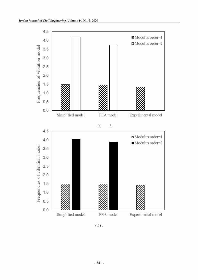
Power Transmission Tower Dynamic Characteristics Figure 8 shows the calculation results of the first-
and second-order modes of the simplified model, FEA
model and the experimental model of the transmission
tower, where f x and f y are the translational motion
frequency of vibration mode in the X and Y directions
and f z is the torsional frequency. The results show that
the inherent frequency calculated by the simplified
model is rather close to that of the FEA model and the
experimental model. Compared to the FEA results, the
maximum errors between the first-order and the second-
order frequency of vibration mode are only 6.1% and
12.7%, respectively. Compared to the experimental
results, the errors for the first order in the X and Y
directions are 11% ad 4%, respectively. The coupling
causes the torsional freedom and the corresponding
vibration frequency to appear within the model. Figure
9 shows the first-order mode of the transmission tower-
line system.
Page 11
Jordan Journal of Civil Engineering, Volume 14, No. 3, 2020
- 341 -
(a) f x
(b) f y
Page 12
Dynamic Characteristics of… Ying Zhou, Shuguo Liang and Lianghao Zou
- 342 -
(c) f z
Figure (8): Frequencies of vibration mode of the transmission tower
Figure (9): First-order vibration mode of the tower-line system
Page 13
Jordan Journal of Civil Engineering, Volume 14, No. 3, 2020
- 343 -
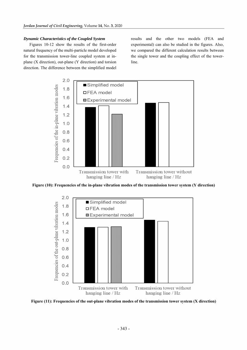
Dynamic Characteristics of the Coupled System Figures 10-12 show the results of the first-order
natural frequency of the multi-particle model developed
for the transmission tower-line coupled system at in-
plane (X direction), out-plane (Y direction) and torsion
direction. The difference between the simplified model
results and the other two models (FEA and
experimental) can also be studied in the figures. Also,
we compared the different calculation results between
the single tower and the coupling effect of the tower-
line.
Figure (10): Frequencies of the in-plane vibration modes of the transmission tower system (Y direction)
Figure (11): Frequencies of the out-plane vibration modes of the transmission tower system (X direction)
Page 14
Dynamic Characteristics of… Ying Zhou, Shuguo Liang and Lianghao Zou
- 344 -
Figure (12): Frequencies of the torsional vibration modes of the transmission tower system
For the transmission tower-line system, by
comparison of the self-vibration frequency of the wire
under the condition of hanging and non-winding wire, it
can be concluded that the influence of the transmission
line on the frequency of vibration mode of the
transmission tower is insignificant. However, the self-
vibration frequency of the wire has a significant impact
on the torsional direction. After twisting the line, the
torsion frequency of the transmission tower is reduced
by about 34%. Therefore, the transmission tower-line
coupled system considering the torsion effect could
more accurately reflect the dynamic characteristics of
the transmission tower system. If the torsional effect is
not considered, the frequency of the transmission tower
would be overestimated, making the calculations
inaccurate. Since this torsional effect is mainly caused
by power transmission lines, the change in dynamic
characteristics due to torsion may be rather great for
long cantilever transmission tower projects. Therefore,
it is necessary to consider the torsional effects while
designing the span for long cantilever transmission
towers.
Figures 10-12 show that the in-plane, out-plane and
torsional natural frequencies of the transmission tower
calculated by the simplified model are generally close to
FEA and experimental results. The experimental values
are slightly lower than the simplified model values by
13% (Y direction) and 1% (X direction), whereas the
simplified multi-particle model and the FEA model have
a maximum error of less than 7%. These results indicate
that the improved calculation method for the single-
tower multi-particle model is reliable and can be used to
analyze the dynamic characteristics of the tower-line
coupling situation and therefore providing a theoretical
reference and calculation method for the precise
engineering design of the transmission tower. In seismic
design, seismic waves with unilateral degrees of
freedom are often required. Since two-way coupled load
is likely to cause structural torsional effects (Calvi et al.,
2005), the multi-particle model calculation method
considering the torsional effect can accurately reflect the
seismic performance of the transmission tower-line
system (e.g., failure and ductility capacity). Thus, it is
beneficial to civil engineering design such as the design
of damper that performs the vibration control of a power
transmission tower (Tian et al., 2017). It is worth noting
that our simplified model achieves a better simplicity
than the traditional FEA method and can be potentially
used for engineering estimation.
Page 15
Jordan Journal of Civil Engineering, Volume 14, No. 3, 2020
- 345 -
CONCLUSIONS
Based on the exploration of the multi-particle model
of the transmission tower-line system, a simplified
model of the transmission tower-line coupled system is
established in this paper. Considering the cross-arm’s
torsional effect on the upper part of the transmission
tower, the coupling method has been improved by
increasing the degree of freedom. The dynamic
characteristics of the transmission tower and
transmission tower-line coupled system have been
calculated and compared to FEA results and
experimental results. The conclusions are as follows:
The frequency of vibration mode of the tower-line
coupled system calculated by the simplified multi-
particle model established in this paper has a higher
accuracy as compared to the FEA and experimental
results.
By increasing the degree of freedom, we can
consider the coupling effect of transmission tower
by twisting the transmission line. Thus, the dynamic
characteristics of the transmission tower-line
system could be accurately reflected.
Considering the tower-line coupled vibration, the
in-plane, out-plane and torsional frequencies of the
transmission tower under vibration mode are lower
than those of the single tower (without a hanging
line). It is also concluded that the hanging line has
a significant influence on the torsional frequency
under vibration mode.
During the design process of the transmission
tower-line architecture, if the tower-line coupling
effect is not considered, the frequency of the
transmission tower would be overestimated,
making the structural design inaccurate.
Acknowledgements Funding: This research was funded by the National
Natural Science Foundation of China, grant number 51078296.
REFERENCES
Calvi, G.M., A. Pavese, A. Rasulo, and D. Bolognini.
(2005). “Experimental and numerical studies on the
seismic response of RC hollow bridge piers”. Bulletin
of Earthquake Engineering, 3, 267-297; doi:10.
1007_s10518-005-2240-0.
Chen, Z., and X. Zhang. (2010). “Seismic response analysis
of multispan bridge using FEM”. In: ICCTP 2010:
Integrated Transportation Systems: Green, Intelligent,
Reliable, 3102-3109.
Chunxiang, L., J. Li, and Z. Yu. (2009). “A review of wind-
resistant design theories of transmission tower-line
systems”. Journal of Vibration and Shock, 28, 15-25,
222-223, (In Chinese).
Danesh, M. (2019). “Evaluation of seismic performance of
PBD optimized steel moment frames by means of
neural network”. Jordan Journal of Civil Engineering,
13 (3).
Ghobarah, A., T. S. Aziz, and M. El-Attar. (1996).
“Response of transmission lines to multiple support
excitation”. Engineering Structures, 18, 936-946; doi:
10.1016/s0141-0296(96)00020-x.
Hongnan, Li, and M.L., Qianxin Wang. (1990).
“Simplified aseismic calculation of high voltage system
consisting of long span transmission lines and their
supporting towers”. Earthquake engineering and
engineering vibration, 10, 73-87, (In Chinese).
Huijun, Yin, B.C., and Weilian Zhai. (2002). “Research
advances of transmission tower-line system’s vibration
responses”. Journal of Huazhong University of Science
and Technology (Urban Science Edition), 3, 79-82, (In
Chinese).
Irvine, H. M. (1981). “Cable structure”.
Kunjie, R. (2018). “Vibratiom control of power
transmission tower-line system under strong seismic
conditions”. Master thesis, Shandong University.
Li, H. (1999). “Response spectral method of aseismic
calculation for coupled system of long-span
transmission lines and their supporting towers”. Special
Structures 1996, 13 (2), 18-22 (In Chinese).
Liang, S., and Z. Ma. "An analysis of wind-induced
response for Dashengguan electrical transmission
tower-line system across the Yangtze river."
Proceedings of the 10th International Conference on
Wind Engineering.
Page 16
Dynamic Characteristics of… Ying Zhou, Shuguo Liang and Lianghao Zou
- 346 -
Liang, S., J. Zhu, and L. Wang. (2003). “Analysis of
dynamic characters of electrical transmission tower-
line system with a big span”. Earthquake Engineering
and Engineering Vibration, 23, 63-69, (In Chinese).
Liang, S., L. Zou, D. Wang, and H. Cao. (2015).
“Investigation on wind tunnel tests of a full Aeroelastic
model of electrical transmission tower-line system”.
Engineering Structures, 85, 63-72;
doi:10.1016/j.engstruct.2014.11.042.
Meigen, Cao, Q. Z., Zenglu and Mo et al. (2007). “Current
research status of HV transmission line earthquake
prevention and disaster relief and earthquake
countermeasures”. Electric Power Construction, 28,
23-27, (In Chinese).
Ozono, S., and J. Maeda. (1992). “In-plane dynamic
interaction between a tower and conductors at lower
frequencies”. Engineering Structures, 14, 210-216; doi:
10.1016/0141-0296(92)90009-F.
Ozono, S., J. Maeda, and M. Makino. (1988).
“Characteristics of in-plane free vibration of
transmission line systems”. Engineering Structures, 10,
272-280; doi: 10.1016/0141-0296(88)90049-1.
Qianxin Wang, M.L., and Hongnan Li. (1989).
“Reasonable computation schema for earthquake-
resistant analysis of the system consisting of
transmission line and its supporting towers”.
Earthquake Engineering and Engineering Vibration, 9,
81-90, (In Chinese).
Qifeng, L. (1997). “Damages to life-line systems caused
earthquake in southern Hyogoken, Japan and their
recovery”. Journal of Catastrophology, 12, 43-48, (In
Chinese).
Shatnawi, A.S., and Al-Qaryouti, Y.H. (2018). “Evaluating
seismic design factors for reinforced concrete frames
braced with viscoelastic damper systems”. Jordan
Journal of Civil Engineering, 12 (2).
Tian, L., K. Rong, P. Zhang, and Y. Liu. (2017). “Vibration
control of a power transmission tower with pounding
tuned mass damper under multi-component seismic
excitations”. Applied Sciences, 7, 477, (In Chinese).
Xia, L. (2013). “The research on wind effects of power
transmission tower with long cross-arms”. Master
Thesis, Zhejiang University, Hangzhou.