Date post: | 14-Apr-2018 |
Category: |
Documents |
Upload: | manishchaturvedi6 |
View: | 218 times |
Download: | 0 times |
7/30/2019 Dynamic Control and Performance of a Unified06
http://slidepdf.com/reader/full/dynamic-control-and-performance-of-a-unified06 1/8
IEEE TRANSACTIONS ON POWER ELECTRONICS, VOL. 21, NO. 4, JULY 2006 1013
Dynamic Control and Performance of a UnifiedPower Flow Controller for Stabilizing
an AC Transmission SystemHideaki Fujita , Member, IEEE , Hirofumi Akagi , Fellow, IEEE , and Yasuhiro Watanabe
Abstract—This paper presents dynamic control and perfor-mance of a unified power flow controller (UPFC) intended forinstallation on a transmission system consisting of two sets of three-phase transmission lines in parallel. When no UPFC isinstalled, interruption of either three-phase line due to a faultreduces an active power flow to half, because the line impedancebecomes double before the interruption. Installing the UPFCmakes it possible to control an amount of active power flowingthrough the transmission system. The validity of the theoreticalanalysis developed in this paper is verified by experiments using a10-kVA laboratory setup, as well as a computer simulation.
Index Terms—Line interruption, power swings, transmissionsystems, unified power flow controller (UPFC).
I. INTRODUCTION
THE unified power flow controller (UPFC) [1]–[3], which
is one of the most promising devices in the FACTS con-
cept, has been researched and put into practical use. The Amer-
ican Electric Power (AEP) company has built and installed a
160-MVA UPFC at the Inez substation in eastern Kentucky for
the first time in the world [4], [5]. The UPFC consists of com-bined series and shunt devices, and the dc terminals which are
connected to a common dc-link capacitor. The series device
controls active power flow from the sending to the receiving
end by means of adjusting the phase angle of the output voltage.
On the other hand, the shunt device performs regulation of the
dc-link voltage as well as control of reactive power. The UPFC
realizes power flow control, stability improvement, and so on.
Damping performance against the so-called “power swings”
is essential to improving the sending capacity of a power trans-
mission system. The power swings are low-frequency oscilla-
tions of active and reactive powers, which are caused by res-
onance between a line inductance and a moment of inertia in
synchronous generators. The oscillating frequency of the power
swings is usually in a range from 0.3 to 2 Hz. Thus, a conven-
tional UPFC for the purpose of damping out the power swings
is designed to have a response time as slow as about 100 ms in
power flow control. Line-to-line and line-to-ground faults may
cause a considerable variation in power flow as fast as 10 ms.
Manuscript received June 17, 2004; revised March 24, 2005. Recommendedby Associate Editor V. Staudt.
H. Fujita and H. Akagi are with the Tokyo Institute of Technology, Tokyo152-8552, Japan (e-mail: [email protected]; [email protected]).
Y. Watanabe is with the Japan Atomic Energy Agency, Ibaraki 319-1195,Japan (e-mail: [email protected]).
Digital Object Identifier 10.1109/TPEL.2006.876845
Fig. 1. Circuit configuration of a UPFC used for experiment.
However, the conventional UPFC could not mitigate such a vari-
ation. A fast response is required for a UPFC to eliminate the
variation from power flow. Dynamic control methods based on
feedback control of instantaneous active and reactive power has
been proposed to realize fast power flow control [6], [12]. The
authors have already proposed the “advanced control method,”which is characterized by providing a response as fast as 3 ms
in power flow control without any oscillation or overshoot [13],
[14]. This paper presents dynamic control and behavior of a
UPFC under a fault condition in a transmission system con-
sisting of two parallel three-phase lines.
II. EXPERIMENTAL SYSTEM CONFIGURATION
Fig. 1 shows the laboratory setup of the UPFC used in the fol-
lowing experiments and simulations. The circuit parameters of
the UPFC are shown in Table I. The main circuit of the series de-
vice consists of three single-phase H-bridge voltage-source in-verters rated at 1 kVA. The inverters perform ac voltage control
by means of pulsewidth modulation (PWM) with a switching
frequency of 1 kHz. The ac terminals of each H-bridge inverter
are connected in series to the transmission line through a single-
phase transformer with a turns ratio of 1:12.
It is possible to replace the three single-phase inverters with
a three-phase inverter. The circuit configuration using three
single-phase inverters seems to be suitable for implementation
of a practical UPFC rated at 100 MVA or higher. Each leg in
such a large-rating converter generally consists of series and/or
parallel connection of high-voltage large-current switching de-
vices. The volt-ampere rating of the three single-phase inverters
0885-8993/$20.00 © 2006 IEEE
7/30/2019 Dynamic Control and Performance of a Unified06
http://slidepdf.com/reader/full/dynamic-control-and-performance-of-a-unified06 2/8
1014 IEEE TRANSACTIONS ON POWER ELECTRONICS, VOL. 21, NO. 4, JULY 2006
TABLE I
SYSTEM PARAMETERS OF THE EXPERIMENTAL SYSTEM
Fig. 2. Experimental system configuration.
is twice as large as that of the three-phase inverter, when each
leg of the inverters consists of the same number of the same
switching devices. Moreover, the three single-phase inverters
produce less switching ripples than the three-phase inverter.
The shunt device consists of a three-phase PWM inverter,
the ac terminals of which are connected in parallel with the
transmission line via a three-phase transformer with a turns
ratio of 2:1. The shunt device regulates the dc-link voltage
as 200 V. A practical shunt device may consist of a
multilevel inverter. However, the simple three-phase inverter is
introduced to the experimental setup, because this paper pays
attention to the control and performance of the series device.For the same reason, no reactive-power control is achieved in
the shunt device.
Fig. 2 shows the 10-kVA laboratory model including a trans-
mission system consisting of two sets of three-phase lines; lines
1 and 2. Here, and is assumed to be sending- and re-
ceiving-end voltages, respectively. The model assumes that the
sending end corresponds to a power plant while the receiving
end to an electric power network. The receiving-end voltage
may not cause any phase-angle change, because can be
considered as an infinite-bus voltage. The phase angle of is
adjusted according to a power demand for the power plant. A
phase-shifting transformer is employed to produce a difference
in phase angle between the sending-end and receiving-end volt-ages [14]. The UPFC installed near the sending end effectively
Fig. 3. Control circuit of the series device.
controls power flow from the sending to the receiving end. In-
ductors and represent line inductance in each transmis-
sion line.
A three-phase solid-state relay (SSR) installed in series with
line 1 is used as a line breaker to simulate the interruption of
line 1. The SSR remains closed in a normal condition. While it
is opened for a few cycles, the total line impedance increases,so that the power flow decreases. In an actual power system, a
periodic change in the rotor speed and angle of a synchronous
generator induces power swings. If the power swings exceeded
a stable region, the generator would fall into out-of-phase
conditions.
III. CONTROL METHODS
Fig. 3 shows a block diagram of the control circuit for the
series device. The three–two-phase transformation obtains
and from the three-phase currents and . Then the
– transformation is applied with the help of sinusoidal sig-
nals of and . These blocks are implemented byusing analog multipliers and operational amplifiers. The phase
information is generated by a phase-lock-loop (PLL) circuit.
The and signals are obtained by connecting dig-
ital-to-analog converters to a read only memory (ROM). Thus,
the control circuit shown in Fig. 3 has almost no delay. The
PWM operation of the inverter produces the most dominant
delay. This delay in the experimental setup is about 0.5 ms, be-
cause the switching frequency is 1 kHz.
The following sections discuss transient responses of the
“cross-coupling control method” in [7] and the “advanced
control method” in [13]. A main difference between the two
methods exists in whether they can damp out power swings.
The cross-coupling control method is based on voltage and
current phasors, while the advanced control method starts from
differential equations in the transient states. The advanced con-
trol method makes it possible to improve its transient stability
even when its feedback gains are higher than that in cross-cou-
pling control method. As a result, the advanced control method
brings a faster response to active and reactive power than the
cross-coupling control method [13].
A. Cross-Coupling Control Method
The “cross-coupling control method” in [7] has two control
gains, and , for active- and reactive-power feedbacks.
This makes it possible to control both active and reactive powersindependently. Integral gains are widely applied for a practical
7/30/2019 Dynamic Control and Performance of a Unified06
http://slidepdf.com/reader/full/dynamic-control-and-performance-of-a-unified06 3/8
FUJITA et al.: DYNAMIC CONTROL AND PERFORMANCE OF A UNIFIED POWER FLOW CONTROLLER 1015
feedback control in order to reduce steady-state error. The cross-
coupling control method with integral gains gives the following
voltage references and to the series device:
(1)
where and are proportional gains for active and reactivepowers, respectively, and is a integral gain [8]–[11].
B. Advanced Control Method
The “advanced control method” in [13] has an additional con-
trol gain for the purpose of improving the stability of the
active- and reactive-power control. The voltage references
and are given by the following equation:
(2)
where is a control gain capable of damping out power
swings.
IV. TRANSFER FUNCTIONS OF THE TRANSMISSION SYSTEM
Fig. 2 gives the following three-phase voltage and current
equation:
(3)
where and are line inductance and resistance in parallel
connection of lines 1 and 2. Applying three-to-two-phase con-version and – transformation to (3) can be represented by
(4)
Here, is a current component corresponding to an active
power, while corresponds to a reactive power. This means
that is in phase with the -phase supply voltage, while is
perpendicular to it. (4) assumes 0, because the receiving
end is assumed to be connected to an infinite bus. Equation (4)
gives the following transfer functions from the output voltage
of the series device to the line current:
(5)
where
(6)
(7)
(8)
The transfer functions and exhibit a second-order
response with a resonant angular frequency of . The existenceof results in cross couplings of with and with
Fig. 4. Bode diagrams of the transmission line,G ( s )
andG ( s )
whenR =
0.02 , and L = 0.5 mH.
. The resonant angular frequency appears very close to ,
because in a transmission line.
Fig. 4 shows the bode diagrams of and . In a
frequency range lower than 60 Hz, is higher than
in gain, and the phase angle is almost zero. Thus, adjusting
can control effectively, while can control . This
means that the cross-coupling control may operate in the low-
frequency range successfully. On the other hand, shows
a high gain in a frequency range higher than 60 Hz, comparedwith . Therefore, in (2) is more effective than and
for controlling and in the high-frequency range. There-
fore, the “advanced control method” may show dynamic perfor-
mance better than the cross-coupling control and phase control
methods.
V. TRANSIENT RESPONSE WHEN NO UPFC IS INSTALLED
This section discusses transient response of the active power,
considering the line inductance change from to
due to a line fault. For the sake of simplicity, it is assumed
that the -axis voltage on the sending end is equal to that on the
receiving end, that is, . Substituting 0 and
0 to (5) gives a step response of the -axis current
as follows:
(9)
From (9), the initial current just before occurrence of the
line fault is given by
(10)
7/30/2019 Dynamic Control and Performance of a Unified06
http://slidepdf.com/reader/full/dynamic-control-and-performance-of-a-unified06 4/8
1016 IEEE TRANSACTIONS ON POWER ELECTRONICS, VOL. 21, NO. 4, JULY 2006
and the final value is
(11)
Taking and into account, a transient response of is
represented as
(12)
The time response of can be obtained as follows:
(13)
The dc component of continues to decrease during the line
fault, while an ac component with the line frequency appears in
. In order to eliminate the ac component from , the UPFC
requires capability of power flow control as fast as 2–3 ms.
VI. TRANSIENT RESPONSE WHEN THE UPFC IS INSTALLED
A. Cross-Coupling Control Method
Let us consider the transient response of the transmission
system with an UPFC, to which the cross-coupling control is
applied.
1) In Case of No Integral Gain: For the sake of simplicity,
the integral gain in (1) is neglected as follows:
(14)
As shown in Fig. 4, the cross-coupling control are applicable to a
frequency range lower than . In this range, almost no coupling
appears between and because .
Paying attention to the resonant angular frequency ,
the following approximations are derived:
(15)
(16)
Although both transfer functions have the same amplitude, thephase angle of lags by 90 . If 2 and 2 , the
open-loop gain is 0 dB and the phase margin is 90 . However,
increasing and tends induce overshoots and oscillations,
because the phase angle of is almost 180 in the frequency
range over . In order to avoid the overshoot and oscilla-
tions, the control gains and should be set as
(17)
The gain of at 0 is given by
(18)
Invoking the approximation in (18)) results in the following
steady-state error in active power:
(19)
When the gain is set as (17), a large amount of steady-state
error may appear in active power.
2) In Case of Having the Integral Gain: In particular, the in-
tegral gains are more dominant than the proportional gains in a
low frequency range of . Applying the approxima-
tion in (18), the transfer function of the whole system is given
by
(20)
The time constant of the transfer function is
(21)
The approximation in (18) is applicable for a steady state or a
slow transient state. Therefore, the time constant has to be larger
than 1 , in order to avoid the coupling between active and
reactive power:
1(22)
The requirement for the integral gain is summarized as
(23)
From (19) to (23), the time response of the active power con-
trol with the proportional and integral gain can be represented
as follows:
(24)
Note that (24) is valid only for a slow transient response
without any overshoot nor oscillation in active power. The error
equal to (19) appears in at the instant of occurrence of the
line fault. However, the active power gradually recovers with
the time constant of . The final value of (24) is equal to its ini-
tial value of . Thus, no steady-state error exists.
B. Advanced Control Method
1) In Case of No Integral Gain: The voltage reference for the
advanced control method in (2) is represented by the following
equation, when the integral gain is neglected:
(25)
7/30/2019 Dynamic Control and Performance of a Unified06
http://slidepdf.com/reader/full/dynamic-control-and-performance-of-a-unified06 5/8
FUJITA et al.: DYNAMIC CONTROL AND PERFORMANCE OF A UNIFIED POWER FLOW CONTROLLER 1017
Assuming in (5) makes almost no change in
even during the line fault. Substituting (25) into (5) obtains the
following simplified equation related with :
(26)
The -axis current is controlled by the difference between
itself and its reference . Therefore, (26) is assumed as a
feedback control of . The open-loop transfer function of the
assumed feedback control, which is a transfer function from
to , is given by
(27)
Neglecting the line resistance derives the approximated fre-
quency response of
(28)
In a frequency range higher than , the phase angle of is
represented by
(29)
The gain contributes to increasing the phase angle. Thephase margin is more than 60 when is set to be two. In
the case of the cross-coupling control method, the phase angle
in (29) is 180 , because the gain is equal to zero. Thus,
almost no phase margin exists in the cross-coupling control.
The steady-state error of the advanced control method is
also obtained by (19). The gains and can be set to a
large value, compared with the cross-coupling control method,
because the cross-coupling control method has the limitation
shown in (17). Setting makes it possible to reduce
the steady-state error in (19).
2) In Case of Having the Integral Gain: Equation (24) is de-
rived for the cross-coupling control method under a assumption
of a slow transient response. This equation is also applicable to
the advanced control method when the time constant in (20)
is adequate to the range shown in (22). The advanced control
method has capability of reduction of the error in at the instant
of occurrence of the line fault, because the advanced control
method allows setting a higher gain than the cross-coupling
control method does. As a result, the advanced control method
makes it possible to maintain almost constant even under the
line fault condition.
VII. EXPERIMENTAL RESULTS
The control parameters used in experiment and simulationare summarized in Table II. The proportional gains in the cross-
TABLE II
GAIN SETTINGS FOR THE EXPERIMENTS AND SIMULATIONS
TABLE IIIVALUES OF
,! ; 1 I = I
, AND
couplingcontrol method are set to 0.05 V/A. Since
these gains are slightly greater than the values in (17), a small
amount of overshoot appears in power flow. The integral gains
are set as 2.5 V/A/s. Then, the time constant shown in
(21) is 75 ms during the SSR is opened, while it is
38 ms during the SSR is closed.
The proportional gains and in the advanced control
are set to 0.5 V/A, which are ten times as large as
those in the cross-coupling control. The gain is set to
0.9 V/A, so that the damping factor is 0.8. The integral gain isalso set to 0.5 V/A/s, and thus, the time constant is one
tenth of that in cross-coupling control method. Table III shows
damping factor , resonant angular frequency , error in active
power , and time constant . The time constant of the
advanced control method is 4 ms during the SSR is turned on,
as shown in Table III. The time constant dominates the transient
performance of active and reactive powers because it is eight
times as long as a delay time of 0.5 ms that is caused by PWM
with a switching frequency of 1 kHz. Therefore, the delay time
has almost no effect, although the delay time is not considered
in the analysis in the previous section. However, the delay time
may cause a stability problem in the active- and reactive-powercontrol if the time constant were close to or less than the delay
time.
Figs. 5 –10 show simulated and experimental waveforms. The
SSR installed in series with line 1 had been turned on before the
marked point (SSR off), it remained turned off for ten cycles
(200 ms), and then, it was turned on again at the other marked
point (SSR on). An actual amount of active power flow was set
to 10 kW by adjusting the phase-shift transformer, when the
SSR was turned on and the UPFC was not installed. In this situ-
ation, a reactive power of 3 kvar was flowing through the trans-
mission lines. The computer simulation was carried out by using
the EMTDC software package. An ideal switch model was used
as the SSR, and it was programmed to be turned off at a zero-cur-rent point [15].
7/30/2019 Dynamic Control and Performance of a Unified06
http://slidepdf.com/reader/full/dynamic-control-and-performance-of-a-unified06 6/8
1018 IEEE TRANSACTIONS ON POWER ELECTRONICS, VOL. 21, NO. 4, JULY 2006
Fig. 5. Simulated waveforms when no UPFC controls active and reactivepowers.
Fig. 6. Experimental waveforms when no UPFC controls active and reactivepowers.
A. No UPFC
Figs. 5 and 6 show simulated and experimental waveforms
when no UPFC controls active and reactive powers. In this ex-
periments, the lower-arm switching devices of the H-bridge in-
verter are turned on, while the upper-arm devices remain off.
Thus, the ac terminal voltage of the inverter should be zero.However, a small amount of voltage appears in , as shown in
Fig. 7. Simulated waveforms when the cross-coupling control method isapplied.
Fig. 8. Experimental waveforms when the cross-coupling control method isapplied.
Fig. 6. It is caused by the leakage inductance of the single-phase
transformer.
The active power decreased from 10 to 5 kW within 5 ms
after the SSR was turned off. After the SSR was turned on, the
active power regained to 10 kW with an overshoot of 3 kW.
Fig. 6 has a smaller overshoot in than Fig. 5, because anon-state resistance exists in the SSR used in this experiment.
7/30/2019 Dynamic Control and Performance of a Unified06
http://slidepdf.com/reader/full/dynamic-control-and-performance-of-a-unified06 7/8
FUJITA et al.: DYNAMIC CONTROL AND PERFORMANCE OF A UNIFIED POWER FLOW CONTROLLER 1019
Fig. 9. Simulated waveforms when the advanced control method is applied.
Fig. 10. Experimental waveforms when the advanced control method isapplied.
A practical system may show a good agreement with the simu-
lation results, because a practical line breaker has a very small
resistance.
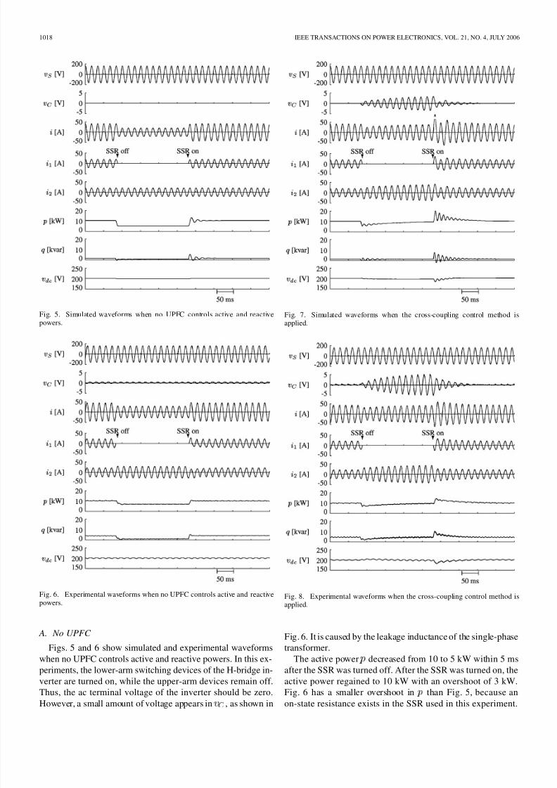
B. UPFC With the Cross-Coupling Control Method
Experimental and simulation results using the cross-coupling
control are shown in Figs. 7 and 8, respectively. The activepower decreases to 5 kW after the SSR was turned off similarly
to the case of no UPFC, because and were a small gain
of 0.05 V/A. After that, the active power gradually increased to
10 kW by the integralgains. A large amount of overshoot and os-
cillations appeared in the active power and reactive power when
turning the SSR on, because the integral gains could not respond
to the rapid change of the line impedance. While active power in
Fig. 8 had almost no oscillation, a large amount of oscillationsappear in Fig. 7. In the simulation, any resistor is considered in
SSR, so that large oscillations appear in Fig. 7.
C. UPFC With the Advanced Control Method
Figs. 9 and 10 show simulated and experimental waveforms
when applying the advanced control. The active power was kept
as 10 kW during the fault, because the gains and were
set to 0.5 V/A, which is ten times as large as that in Figs. 7 and
8. Since the gain has the capability of damping the active
and reactive power oscillations, no overshoot nor oscillations
appeared in the active and reactive power. These results reveal
that the advanced control makes it possible to significantly im-
prove stability of transmission systems.
VIII. CONCLUSION
This paper has presented dynamic control and performance
of a UPFC under a fault condition in a two-parallel three-phase
transmission system. The transient analysis clarifies that a line
interruption generally causes a transition in the active power as
fast as 2–3 ms. Thus, a conventional UPFC with a response as
slow as100ms has dif ficulty in suppressing the power variations
caused by the faults. Moreover, a conventional UPFC may cause
an overcurrent after finishing the fault, due to the slow response
of the integral gains in the control loop for the activeand reactive
power. The advanced control in this paper shows good transientperformance without any overshoot or oscillation. The advanced
control may contribute not only to achieving fast power flow
control but also to improvement of stabilizing the transmission
systems.
REFERENCES
[1] L. Gyugyi, “Unified power-flow control concept for flexible ac trans-mission systems,” Proc. Inst. Elect. Eng. C , vol. 139, pp. 323–331, Jul.1992.
[2] L. Gyugyi, C. D. Schauder, S. L. Williams, T. R. Rietman, D. R. Torg-erson,and A. Edris, “Theunified power flowcontroller: a newapproachto power transmission control,” IEEE Trans. Power Del., vol. 10, no.2, pp. 1085–1097, Oct. 1995.
[3] N. G. Hingorani and L. Gyugyi , UnderStanding FACTS: Concept and
Technology of FlexibleAC Transmission Systems. Piscataway, NJ:IEEE Press, 2000.
[4] C. Schauder, E. Stacey, M. Lund, L. Gyugyi, L. Kovalsky, A. Keri, A.Mehraban, and A. Edris, “AEP UPFC project: Installation, commis-sioning and operation of the /spl plusmn/160 MVA STATCOM (phase
I),” IEEE Trans. Power Del., vol. 13, no. 4, pp. 1530–1535, Nov. 1998.[5] B. A. Renz, A. Keri, A. S. Mehraban, C. Schauder, E. Stacey, L. Ko-
valsky, L. Gyugyi, and A. Edris, “AEP unified power flow controllerperformance,” IEEE Trans. Power Del., vol. 14, no. 4, pp. 1374–1381,Nov. 1999.
[6] B.S. RigbyandR. G.Harley, “An improved controlscheme for a seriescapacitive reactance compensator based on a voltage source inverter,”in Proc. IEEE/IAS Annu. Meeting, 1996, pp. 870–877.
[7] Q. Yu, S. D. Round, L. E. Norum, and T. M. Undeland, “Dynamiccontrol ofa unified power flow controller,” in Proc. IEEE/PELS PES’96 Conf., 1996, pp. 508–514.
[8] Y. Jiang and A. Ekstrom, “Optimal controller for the combinationsystem of a UPFC and conventional series capacitors,” in Proc. EPE’97 , 1997, vol. 1, pp. 372–337.
7/30/2019 Dynamic Control and Performance of a Unified06
http://slidepdf.com/reader/full/dynamic-control-and-performance-of-a-unified06 8/8
1020 IEEE TRANSACTIONS ON POWER ELECTRONICS, VOL. 21, NO. 4, JULY 2006
[9] Y. Chen, B. Mwinyiwiwa, Z. Wolanski, and B. T. Ooi, “Unified powerflow controller (UPFC) based on chopper stabilized multilevel con-verter,” in Proc. IEEE/PELS PESC ’97 Conf., 1997, pp. 331–337.
[10] L. Gyugyi, C. D. Schauder, and K. K. Sen, “Static synchronous se-ries compensator: A solid-state approach to the series compensationof transmission lines,” IEEE Trans. Power Del., vol. 12, no. 1, pp.406–413, Feb. 1997.
[11] L. Gyugyi, C. D. Schauder, and K. K. Sen, “Improving power system
dynamics by series-connected FACTS device,” IEEE Trans. Power Del., vol. 12, no. 4, pp. 1635–1641, Nov. 1997.[12] B. T. Ooi, M. Kazerani, R. Marceau, and Z. Wolanski, “Mid-point
siting of FACTS devicein transmissionlines,” IEEE Trans. Power Del.,vol. 12, no. 4, pp. 1717–1722, Nov. 1997.
[13] H. Fujita, Y. Watanabe, and H. Akagi, “Control and analysis of a uni-fied power flow controller,” IEEE Trans. Power Electron., vol. 14, no.6, pp. 1021–1027, Nov. 1999.
[14] H. Fujita, Y. Watanabe, and H. Akagi, “Transient analysis of a unifiedpower flow controller and its application to design of the DC-link ca-pacitor,” IEEE Trans. Power Electron., vol.16,no.5, pp. 735–740,Sep.2001.
[15] H. Fujita, S. Tominaga, and H. Akagi, “Analysis and design of a dcvoltage-controlled static var compensator using quad-series voltage-source inverters,” IEEE Trans. Ind. Appl., vol. 32, no. 4, pp. 970–978,Jul./Aug. 1996.
Hideaki Fujita (M’91) received the B.S. and M.S.degrees in electrical engineering from the NagaokaUniversity of Technology, Nagaoka, Japan, in 1988and 1990, respectively.
In 1991, he became a Research Associate with theOkayama University, Okayama, Japan. Since 2002,he hasbeen an AssociateProfessorin the Departmentof Electrical Engineering, Tokyo Institute of Tech-nology, Tokyo, Japan.His research interests are static
var compensators, active power filters, and resonantconverters.
Dr. Fujita received Prize Paper Awards from the Industrial Power ConverterCommittee,IEEE Industry ApplicationsSociety, in 1990, 1995, 1998, and2003,respectively.
Hirofumi Akagi (M’87–SM’94–F’96) was bornin Okayama, Japan, in 1951. He received the B.S.degree from the Nagoya Institute of Technology,Nagoya, Japan, in 1974, and the M.S. and Ph.D.degrees from the Tokyo Institute of Technology,Tokyo, Japan, in 1976 and 1979, respectively, all inelectrical engineering.
In 1979, he joined the Nagaoka University of
Technology, Nagaoka, Japan, as an Assistant andthen Associate Professor in the Department of Electrical Engineering. In 1987, he was a Visiting
Scientist at the Massachusetts Institute of Technology (MIT), Cambridge, forten months. From 1991 to 1999, he was a Professor in the Department of Electrical Engineering, Okayama University, Okayama. From March to Augustof 1996, he was a Visiting Professor at the University of Wisconsin, Madison,and then MIT. Since January 2000, he has been a Professor in the Departmentof Electrical and Electronic Engineering, Tokyo Institute of Technology.He has published about 170 peer-reviewed journal papers, including about70 IEEE TRANSACTIONS papers and an invited Proceedings of the IEEE paper.His research interests include power conversion systems, ac motor drives,active and passive EMI filters, high-frequency resonant-inverters for inductionheating and corona discharge treatment processes, and utility applications of power electronics such as active filters, self-commutated BTB systems, andFACTS devices.
Dr. Akagi received two IEEE IAS TRANSACTIONS Prize Paper Awards in
1991 and 2004, two IEEE PELS T RANSACTIONS Prize Paper Awards in 1999and in 2003, nine IEEE IAS Committee Prize Paper Awards, the IEEE WilliamE. Newell Power Electronics Award in 2001, and the IEEE IAS OutstandingAchievement Award in 2004. He has made presentations many times as akeynote or invited speaker internationally. He was elected as a DistinguishedLecturer of the IEEE IAS and PELS for 1998–1999.
Yasuhiro Watanabe was born in Gifu, Japan,on May 16, 1972. He received the B.S. degree inelectrical engineering from Shizuoka University,Hamamatsu City, Japan, in 1995, and the M.S. andPh.D degrees from Okayama University, Okayama,Japan, in 1997 and 2000, respectively.
In 2000, he joined the National Laboratory for
High Energy Accelerator Research. Since 2001, hehas been a Research Scientist in the Japan AtomicEnergy Agency (formerly Japan Atomic EnergyResearch Institute), Ibaraki, Japan. His research
interests are magnet and magnet power supply for synchrotron accelerator.