Dynamic field modelling of torque and radial forces in vector-controlled induction machines with bearing relief U.A. Ungku Amirulddin, G.M. Asher, P. Sewell and K.J. Bradley Abstract: The paper addresses the bearingless induction motor based on the concept of dual-pole windings, one controlling the motor torque and the other the generated radial forces. Such machines have been investigated experimentally in the past. The paper presents a simulation model capable of investigating the effect of induction-machine design on the generation and control of the radial force. The simulation is based on the dynamic reluctance-mesh field model embedded in vector control systems for the decoupled control of torque, flux and radial force. In the paper, the rotor is constrained by a mechanical bearing so that the radial force is used to cancel the rotor weight to effect ‘bearing relief’. The paper summarises the modelling method, investigates the radial force production in both cage and wound rotor machines, and introduces a mixed field orientation method for the decoupled control of the torque and radial forces. Simulations are undertaken showing good generation of radial force under zero speed, acceleration and transient load conditions. List of symbols M ðmÞ number of poles (pole pair) for main winding N ðnÞ number of poles (pole pair) for ‘levitation’ winding B o ðy; tÞ M-pole flux density distribution B M o M-pole peak airgap flux density B F ðy; tÞ N-pole flux density distribution B N F N-pole peak airgap flux density o; o e synchronous speed (electrical) y rotor mechanical angular co-ordinate j phase difference between B M o and B N F m 0 permeability of vacuum r rotor radius L rotor length D rotor diameter f ij flux flowing in a reluctance element con- nected by nodes i and j f i magnetic potential at node i N node total number of nodes in the reluctance mesh R ph winding phase resistance R bar squirrel cage bar resistance N bar number of rotor bars in a squirrel cage rotor F Rmmf value of mmf source associated with each rotor slot fðtÞ flux flowing in reluctance element associated with each stator or rotor slot N turns number of turns linked by flux fðtÞ o r mech rotor mechanical rotational speed T torque produced by machine J rotor moment of inertia B coefficient of friction T load applied load torque w width of reluctance element d depth of reluctance element l length of reluctance element A ¼ wd area of airgap reluctance element l g airgap length in machine and length of airgap reluctance element < gap airgap element reluctance B gap flux density due to the airgap reluctance element, a function of < gap I R a ; I R b ; I R c wound-rotor phase a, b and c currents I M a ; I M b ; I M c stator main-winding phase a, b and c currents I N a ; I N b ; I N c stator ‘levitation’-winding phase a, b and c currents x matrix of state variables, x i x old matrix of state variables previously solved for at time t x new matrix of state variables solved for at time t þ Dt Y ðxÞ matrix of state equations, Y i , solved by the model k M w winding factor of the main winding N M t total number of series turns per phase of the main winding k N w winding factor of the ‘levitation’ winding N N t total number of series turns per phase of the ‘levitation’ winding 1 Introduction Bearingless motors are electric motors capable of producing rotor levitation as well as torque. In recent years research The authors are with the School of Electrical and Electronic Engineering, University of Nottingham, University Park, Nottingham NG7 2RD, UK E-mail: [email protected]r IEE, 2005 IEE Proceedings online no. 20045233 doi:10.1049/ip-epa:20045233 Paper first received 22nd November 2004 and in final revised form 11th March 2005. Originally published online: 20th May 2005 894 IEE Proc.-Electr. Power Appl., Vol. 152, No. 4, July 2005
Transcript
Dynamic field modelling of torque and radial forcesin vector-controlled induction machines withbearing relief
U.A. Ungku Amirulddin, G.M. Asher, P. Sewell and K.J. Bradley
Abstract: The paper addresses the bearingless induction motor based on the concept of dual-polewindings, one controlling the motor torque and the other the generated radial forces. Suchmachines have been investigated experimentally in the past. The paper presents a simulation modelcapable of investigating the effect of induction-machine design on the generation and control of theradial force. The simulation is based on the dynamic reluctance-mesh field model embedded invector control systems for the decoupled control of torque, flux and radial force. In the paper, therotor is constrained by a mechanical bearing so that the radial force is used to cancel the rotorweight to effect ‘bearing relief’. The paper summarises the modelling method, investigates the radialforce production in both cage and wound rotor machines, and introduces a mixed field orientationmethod for the decoupled control of the torque and radial forces. Simulations are undertakenshowing good generation of radial force under zero speed, acceleration and transient loadconditions.
List of symbols
MðmÞ number of poles (pole pair) for main windingNðnÞ number of poles (pole pair) for ‘levitation’
windingBoðy; tÞ M-pole flux density distributionBM
o M-pole peak airgap flux densityBF ðy; tÞ N-pole flux density distributionBN
F N-pole peak airgap flux densityo;oe synchronous speed (electrical)y rotor mechanical angular co-ordinatej phase difference between BM
o and BNF
m0 permeability of vacuumr rotor radiusL rotor lengthD rotor diameterfij flux flowing in a reluctance element con-
nected by nodes i and jfi magnetic potential at node iNnode total number of nodes in the reluctance meshRph winding phase resistanceRbar squirrel cage bar resistanceNbar number of rotor bars in a squirrel cage rotorFRmmf value of mmf source associated with each
rotor slotfðtÞ flux flowing in reluctance element associated
with each stator or rotor slotNturns number of turns linked by flux fðtÞor mech rotor mechanical rotational speed
T torque produced by machineJ rotor moment of inertiaB coefficient of frictionTload applied load torquew width of reluctance elementd depth of reluctance elementl length of reluctance elementA ¼ wd area of airgap reluctance elementlg airgap length in machine and length of
airgap reluctance element<gap airgap element reluctanceBgap flux density due to the airgap reluctance
element, a function of <gap
IRa ; I
Rb ; I
Rc wound-rotor phase a, b and c currents
IMa ; I
Mb ; I
Mc stator main-winding phase a, b and c
currentsINa ; I
Nb ; I
Nc stator ‘levitation’-winding phase a, b and c
currentsx matrix of state variables, xixold matrix of state variables previously solved
for at time txnew matrix of state variables solved for at time
t þ DtYðxÞ matrix of state equations, Yi, solved by the
modelkM
w winding factor of the main windingNM
t total number of series turns per phase of themain winding
kNw winding factor of the ‘levitation’ winding
NNt total number of series turns per phase of the
‘levitation’ winding
1 Introduction
Bearingless motors are electric motors capable of producingrotor levitation as well as torque. In recent years research
The authors are with the School of Electrical and Electronic Engineering,University of Nottingham, University Park, Nottingham NG7 2RD, UK
Paper first received 22nd November 2004 and in final revised form 11th March2005. Originally published online: 20th May 2005
894 IEE Proc.-Electr. Power Appl., Vol. 152, No. 4, July 2005
has been carried out on different types of bearingless motors[1–6] as an alternative to external magnetic bearings,particularly in high-speed operations. In the proposedbearingless motors, the main M-pole (m pole pair) windingis augmented by an auxiliary N-pole (n pole pair) levitation-winding, such that the interaction between the M- and N-pole fields generates radial forces that can levitate the rotor.Bearingless motors utilising only a single set of windingshave also been put forward [5, 6]. A general theory of pole-number combination for a permanent-magnet synchro-nous-type and induction-motor-type bearingless motor wascarried out in [7] showing that the condition M � N ¼�2ðm� n ¼ �1Þ produces a constant radial force acting onthe rotor.
Research into induction-type bearingless motors having a4-pole main winding and 2-pole levitation winding hasexperimentally studied the possibility of controlled radialforces suitable for levitation under no-load [3] and load [4]conditions. These experiments used a vertical rig with oneend of the shaft held by bearings. No true levitation of abearingless induction machine has been reported. Theproblem is a challenging one, under load, 2-pole levitationcurrents are induced in the cage which cause lower thanexpected forces as well as introducing a phase delay withrespect to the radial force command [8]. To overcome theeffects of the 2-pole rotor currents, phase-lead compensa-tion was introduced in the levitation-winding controllers [8]or else the rotor cage was modified such that only 4-polecurrents were allowed to flow [9]. Field-oriented vectorcontrol schemes for the induction-type bearinglessmotors have also been introduced [6, 10, 11] since thelevitation forces generated are dependent on the phaseinteraction between the fields of the main and levitationwindings.
This paper focuses on induction-type bearingless motors.It is part of a wider research project investigating the effectsof machine design (winding geometries, rotor slotting andsaturation) on radial force generation and motor levitationunder both steady-state and transient conditions. Since nosuccessful experimental levitation has been reported, thestudy uses a modelling approach to investigate the problemsassociated with true bearingless induction motors. Thestudy requires a dynamic magnetic-field model of themachine embedded in a vector-controlled system. Finite-element models are considered inappropriate owing to thevery long computation times associated with the problemdynamics. Therefore, a reduced-complexity reluctance-meshmodel [12–14] is used for solving the fields in the inductionmachine. Since the qualitative direction and spatial varia-tion of the fields in the machine are predictable, withsufficiently good accuracy, from experience, the resultinglumped equivalent-circuit mesh may be coarse in compar-ison with a conventional FEM mesh while still yieldinggood results. In fact, the results obtained from thereluctance-mesh model for conventional induction machinesunder transient conditions have previously shown excellentagreement with experimental results [14].
The paper considers ‘bearing relief’ in vector-controlledinduction motors in which the rotor movement is restrictedby bearings but with the bearing load cancelled by thesuitably directed radial force. The paper will consider theeffects of real winding topologies, stator and rotor slottingand motor skew, but the effects of iron saturation will bediscussed in a future paper. Both the cage and wound-rotorinduction machines are investigated and their suitability forgenerating controlled bearing-relief forces assessed. A mixedfield-oriented vector control scheme is introduced to controlthe radial forces for a wound-rotor machine that is capable
of successful bearing relief under both transient and steady-state conditions.
2 Radial-force generation
In a bearingless induction motor, the stator is wound withan M-pole ‘motoring’ winding and an additional N-pole‘levitation’ winding. The flux density Boðy; tÞ actingperpendicular to rotor surface in the airgap, due to boththe main M-pole-winding stator current and the inducedM-pole rotor current, is assumed sinusoidal and given by
Boðy; tÞ ¼ BMo cosðot � myÞ ð1Þ
Similarly, the additional N-pole stator current and inducedN-pole rotor current are assumed to produce a sinusoidalflux density at the surface the rotor of
BF ðy; tÞ ¼ �BNF cosðot � ny� fÞ ð2Þ
The total magnetic-flux-density distribution in the airgap atthe rotor surface of the induction motor can be expressed as
Bðy; tÞ ¼ Boðy; tÞ � BF ðy; tÞ¼ BM
o cosðot � myÞ þ BNF cosðot � ny� fÞ
ð3Þ
This flux density Bðy; tÞ produces a force acting on aninfinitesimal surface element of the rotor:
DF ðyÞ ¼ Bðy; tÞ2
2m0DS ð4Þ
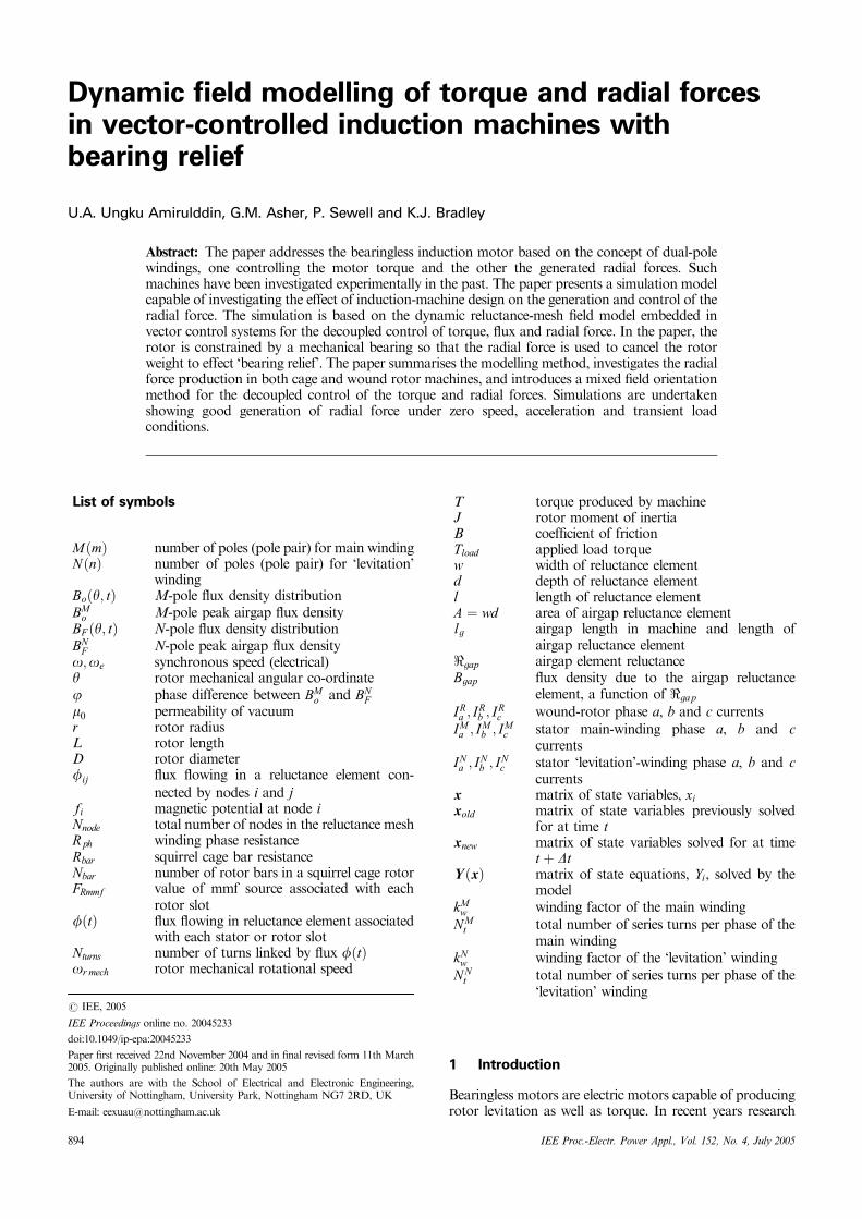
The total force in the y direction is obtained by resolving(4), as shown in Fig. 1, and integrating over the surface ofthe rotor:
Fy ¼Z 2p
0
Z L
0
DF ðyÞr cosðyÞ dzdy
¼ rLBMo BN
F
4m0
Z 2p
0
fcosff� ðm� n� 1Þyg
þ cosff� ðm� nþ 1Þyggdy
ð5Þ
However, when m� n ¼ �1, (5) produces a constant forceof
Fy ¼rLpBM
o
2m0BN
F cosf ð6Þ
Similarly, the x-directional force is obtained by integratingthe horizontal component of (4) to give
Fx ¼ �rLpBM
o
2moBN
F sinf whenm� n ¼ �1 ð7Þ
Unlike Fy , which is positive when m� n ¼ þ1 orm� n ¼ �1, the x-directional force Fx is positive in the
x
y
0°�Fy (�)
�Fx (�)
�F(�)
�
�
Fig. 1 Horizontal and vertical forces on the rotor
IEE Proc.-Electr. Power Appl., Vol. 152, No. 4, July 2005 895
former choice of m�n pole-pair combination and negativein the latter. The magnitude of the force is obtained by
densities of the two components aligned with the y and xaxes, respectively, when BM
o is lying on the y axis. Therefore,the y and x directional forces acting on the rotor can also berepresented as
Fy ¼rLpBM
o
2m0BFy ð10Þ
Fx ¼ �rLpBM
o
2moBFx ð11Þ
when m� n ¼ �1ðM � N ¼ �2Þ. Note that the directionof Fx is dependent on the m�n pole-pair combination.Eqns. (10) and (11) illustrate that the forces can becontrolled by the peak magnitudes of the levitation windingfields BFy and BFx. This result agrees with [7] in that paper’sconsideration of the permanent-magnet machine; for aninduction motor [7] uses a formulation based on inducedcoefficients to account for the fields due to the induced rotorcurrents. This introduces an additional term to be multipliedby (10) and (11) which considerably increases the complex-ity of the force calculations. Furthermore, the IM-forceexpressions (10) and (11) are more consistent with vector-control concepts, compared with those derived by Okada[7], thus making it much more appealing for the drivescommunity.
3 Dynamic-reluctance-mesh model of a bearing-less induction motor
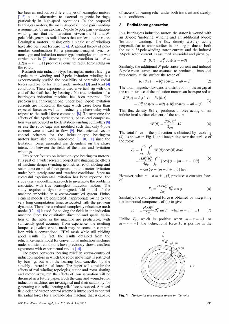
The induction motor is modelled by a computationallyefficient dynamic-reluctance-mesh modelling technique de-veloped by Sewell et al. [14]. In this model, the machinegeometry is discretised into a number of cells in which theflux may be realistically considered to flow perpendicularlyto the intercell boundaries. The discretisation employed toproduce the final mesh shown in Fig. 2 is illustrated inFig. 17 of the Appendix (Section 10). On each boundary, anode is defined, at which point the MMF is sampled,reluctance elements connecting the nodes, as shown inFig. 18. These reluctances are calculated using (45) and theflux flowing through them using (46) and (47).
Each reluctance element corresponds to linear iron,nonlinear iron or ‘air’. In the case of nonlinear iron, asuitable experimental B/H curve defines the permeability;otherwise an appropriate relative-permeability valuemr ¼ constant, is given. The slots on both the stator androtor side can be left open by modelling the reluctanceelement between the teeth as an ‘air’ element.
The model enforces conservation of flux entering eachnode i: X
j
fij fi; fj� �
¼ 0 ð12Þ
As there are a total of Nnode nodes in the reluctance-mesh, aset of equations is recovered linking together all the nodalMMFs f in the simulation. The stator and rotor slots arefilled by a phase winding, or bars for a cage rotor. Thestator possesses two three-phase windings, the main windingand the ‘levitation’ winding, each of which may be woundas either a fractional- or full-pitch double-layer winding.The rotor slots, however, can be wound with a double-layered three-phase winding or filled with bars of a cage.
The magnetic model is coupled to the stator and rotorelectrical models by applying Ampere’s and Faraday’s laws.Satisfaction of Ampere’s law requires placingMMF sourcesin the teeth of both the rotor and stator as shown in Fig. 17.Each of the three phase windings on the stator and thewound rotor comprises three independent phase loops, andknowledge of the winding distribution allows appropriatecurrent to be used in determining each tooth MMF source.For the cage rotor, each bar current is regarded as anindependent quantity. Faraday’s law is enforced for eachindependent electrical loop in the motor. These loopscomprise each of the phases of the stator and wound-rotorwindings. For the cage rotor, the independent electricalloops consist of pairs of adjacent rotor bars. The electricalloops having been defined, the teeth fluxes which couplewith each of them become clear from the windingdistribution of the stator and rotor, and an equation ofthe form
VloopðtÞ � RloopIloopðtÞ � Nturnsddt
Xteeth
fðtÞ ¼ 0 ð13Þ
is formed. Vloop is either the imposed stator or wound-rotorvoltage or 0 for the cage-rotor loops, and Rloop and Nturns areknown from the machine specification.
Finally, the rotor dynamics are encapsulated by
or mech �dydt¼ 0 ð14Þ
T � Jdor mech
dt� Bor mech � Tload ¼ 0 ð15Þ
In (15), T is the torque produced by the motor and iscalculated in the model using the virtual-work principle oneach airgap reluctance element. Based on this principle, thetorque is calculated from the change of magnetic energy dueto a virtual perturbation of the rotor in the y direction [15].Therefore,
T ¼X @E
@yð16Þ
where E is the magnetic energy produced by each airgapreluctance and is given by
E ¼B2
gap
2m0Alg ð17Þ
The model is quasi-three-dimensional, allowing for rotorskew along its axis. The motor is divided into a number of
mainwinding
levitationwinding stator
mesh
rotormesh
Fig. 2 Reluctance-mesh model
896 IEE Proc.-Electr. Power Appl., Vol. 152, No. 4, July 2005
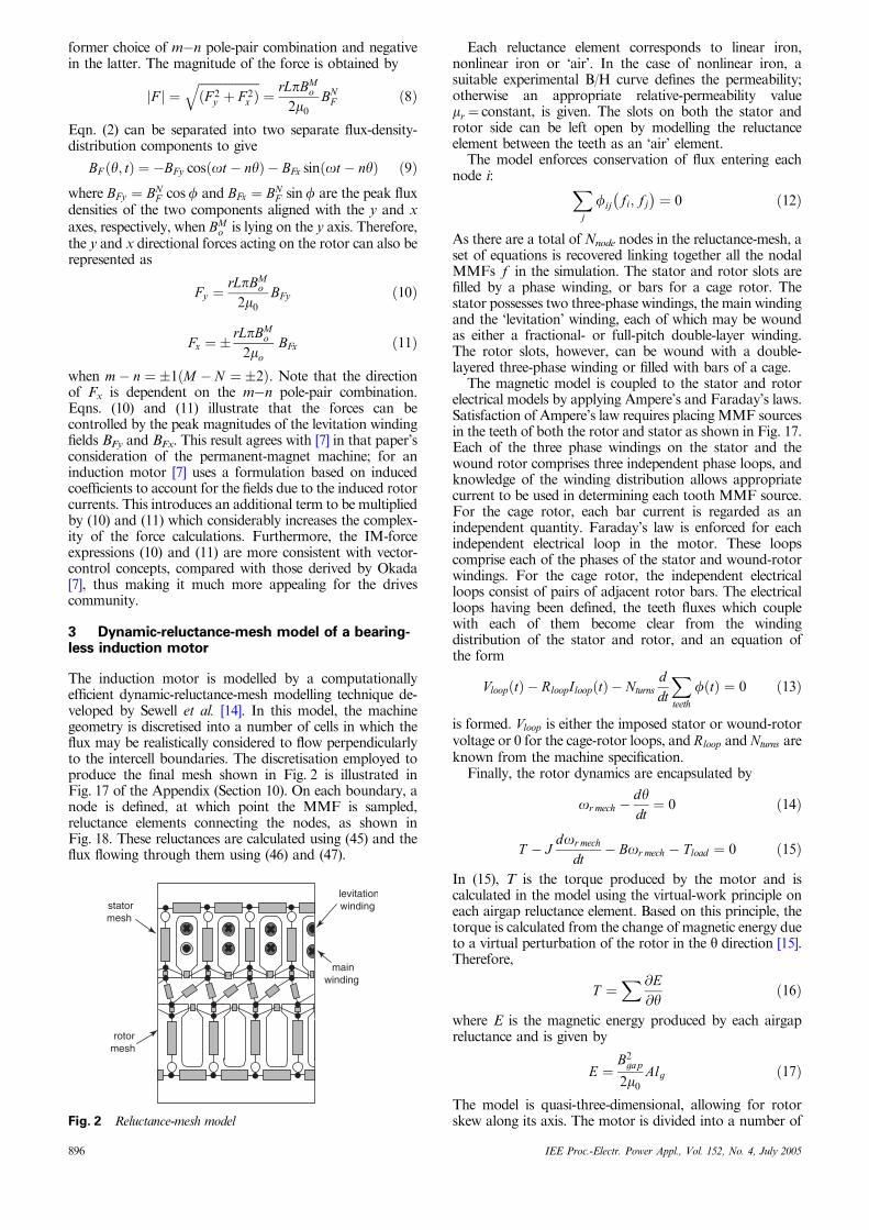
axial sections with each section of the rotor being offsetfrom its predecessor by a small angle to model the skew.Adjacent axial sections are only coupled through the rotorand stator electrical circuits as it is assumed that axiallydirected flux is negligible; this is a physically realisticassumption which dramatically improves the computationalefficiency of the model. Correctly modelling the reluctancemesh of the airgap is crucial in a dynamic simulation. Theairgap-reluctance elements are allocated on the basis of theoverlap area between pairs of rotor and stator tooth tips. Asthe rotor rotates, the overlaps between rotor and statorteeth change and hence the airgap-reluctance-element meshvaries at each time step, as shown in Fig. 3. Flux is assumedto flow radially across the airgap at all times.
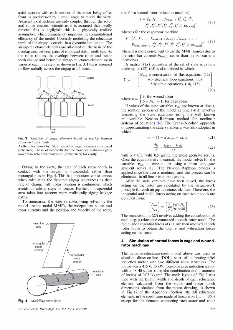
Owing to the skew, the area of each rotor tooth incontact with the airgap is trapezoidal, rather thanrectangular as in Fig. 4. This has important consequenceswhen calculating the dynamic airgap reluctances as theirrate of change with rotor position is continuous, whichavoids unrealistic steps in torque. Further, a trapezoidalarea takes into account more realistically zigzag leakagepaths.
To summarise, the state variables being solved by themodel are the nodal MMFs, the independent stator androtor currents and the position and velocity of the rotor,
where n ¼ 9; for wound rotor6þ Nbar � 1; for cage rotor:
�If values of the state variables xold are known at time t,
the solution process of the model at time t þ Dt involveslinearising the state equations using the well knownmultivariable Newton–Raphson method for nonlinearsystems of equations [16]. The Crank–Nicolson approachof approximating the state variables x was also adopted inwhich
xi ¼ 1� að Þxi new þ axi old ð21Þ
dxi
dt¼ xi new � xi old
Dtð22Þ
with a � 0:5, with 0.5 giving the most accurate results.Once the equations are linearised, the model solves for thevariables xnew at time t þ Dt using a linear conjugategradient solver [17]. The Newton–Raphson process isapplied since the iron is nonlinear and this process can beeliminated in all linear iron simulations.
After the state variables have been solved, the forcesacting on the rotor are calculated by the virtual-workprinciple for each airgap-reluctance element. Therefore, thetangential and radial forces acting on each rotor tooth areobtained from:
Frad
Ftan
� �¼
P@E=@lgP@E=r@y
� �ð23Þ
The summation in (23) involves adding the contribution ofeach airgap reluctance connected to each rotor tooth. Theradial and tangential forces of (23) are then resolved at eachrotor tooth to obtain the total x- and y-direction forcesacting on the rotor.
4 Simulation of normal forces in cage and wound-rotor machines
The dynamic-reluctance-mesh model above was used tosimulate direct-on-line (DOL) start of a bearing-reliefinduction motor with two different rotor structures. Themotor was a 415V, 15kW, four-pole cage induction motorwith a 48–40 stator–rotor slot combination and a momentof inertia of 0.0713kgm2. The mesh layout of Fig. 2 wasused with the length, width and depth of each reluctanceelement calculated from the stator and rotor toothdimensions obtained from the motor drawing, as shownin Fig. 17 of the Appendix (Section 10). All reluctanceelements in the mesh were made of linear iron ðmr ¼ 1350Þexcept for the elements connecting each stator and rotor
rδθ
stator
rotor
Fig. 3 Creation of airgap elements based on overlap betweenstator and rotor toothAs the rotor moves by rdy, a new set of airgap elements are created(solid lines). The set of rotor teeth after the movement is drawn slightlylower than before the movement (broken lines) for clarity
machineaxis
rectangularstator
section
trapezoidalrotor
section
machineaxis
Fig. 4 Modelling rotor skew
IEE Proc.-Electr. Power Appl., Vol. 152, No. 4, July 2005 897
tooth which are of ‘air’ to model the open stator and rotorslots. The motor was also modelled with only one rotoraxial skew section with a skew angle of 151 electrical.
The original four-pole stator winding was maintained asthe main M¼ 4 pole winding with a total of 176 series turnsper phase. The ‘levitation’ winding was chosen as a two-pole (N¼ 2 pole) stator winding wound into the same statorslots with a total of 48 series turns per phase. N¼ 2 waschosen to utilise the fact that a constant force is produced inthe motor when M � N ¼ þ2 as derived in Section 2. Thetwo rotor structures considered were a cage rotor and awound rotor. In the wound rotor the rotor slots wasreduced to 36 to incorporate a short-circuited four-polewinding with 180 turns in series per phase.
According to (8), and with a peak main field BMo of 0.9T,
the levitation winding must produce a peak flux density BNF
of 17mT in order to produce a force of 235N tocompensate for the rotor weight. To achieve a BN
F of17mT, the terminal voltage for the levitation winding wascalculated using
V Nrms ¼
2pf
2p kN
w NNt
BNF 2rLN
ð24Þ
[18] where f ¼ 50Hz frequency and kNw ¼ 0:9562. There-
fore, in both motors simulated, a 415V RMS terminalvoltage was applied to the main four-pole winding togetherwith a voltage of 4.196V RMS applied to the two-polelevitation winding.
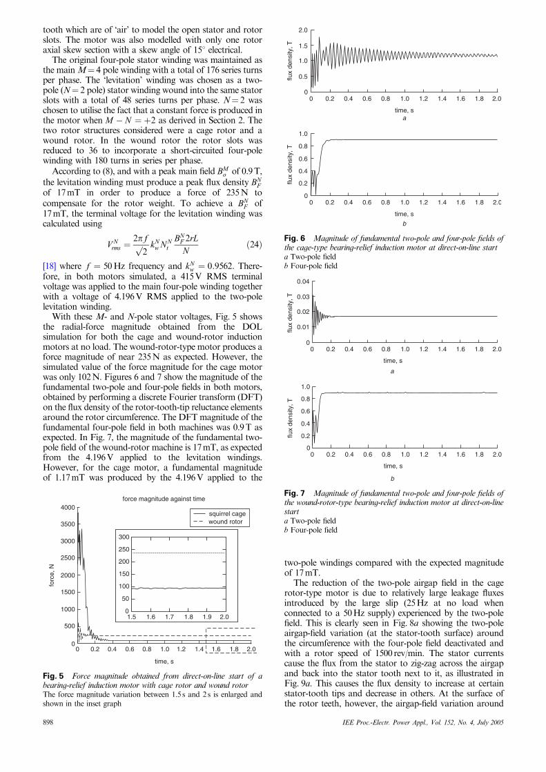
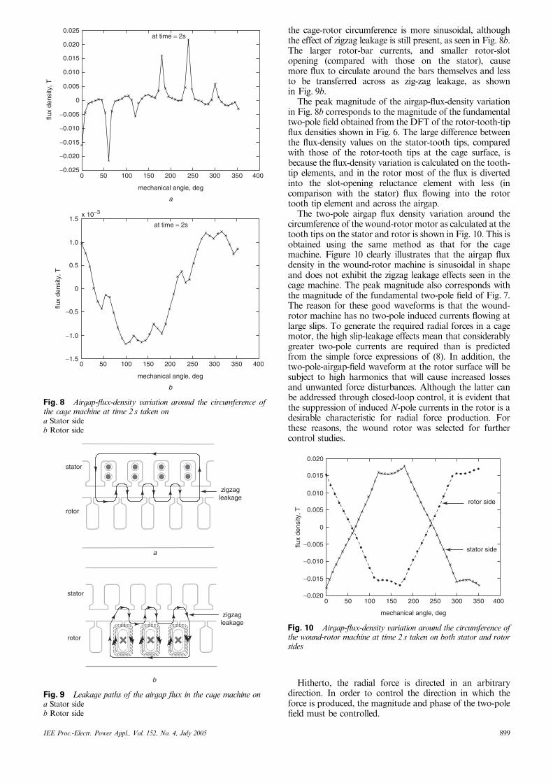
With these M- and N-pole stator voltages, Fig. 5 showsthe radial-force magnitude obtained from the DOLsimulation for both the cage and wound-rotor inductionmotors at no load. The wound-rotor-type motor produces aforce magnitude of near 235N as expected. However, thesimulated value of the force magnitude for the cage motorwas only 102N. Figures 6 and 7 show the magnitude of thefundamental two-pole and four-pole fields in both motors,obtained by performing a discrete Fourier transform (DFT)on the flux density of the rotor-tooth-tip reluctance elementsaround the rotor circumference. The DFTmagnitude of thefundamental four-pole field in both machines was 0.9T asexpected. In Fig. 7, the magnitude of the fundamental two-pole field of the wound-rotor machine is 17mT, as expectedfrom the 4.196V applied to the levitation windings.However, for the cage motor, a fundamental magnitudeof 1.17mT was produced by the 4.196V applied to the
two-pole windings compared with the expected magnitudeof 17mT.
The reduction of the two-pole airgap field in the cagerotor-type motor is due to relatively large leakage fluxesintroduced by the large slip (25Hz at no load whenconnected to a 50Hz supply) experienced by the two-polefield. This is clearly seen in Fig. 8a showing the two-poleairgap-field variation (at the stator-tooth surface) aroundthe circumference with the four-pole field deactivated andwith a rotor speed of 1500 rev/min. The stator currentscause the flux from the stator to zig-zag across the airgapand back into the stator tooth next to it, as illustrated inFig. 9a. This causes the flux density to increase at certainstator-tooth tips and decrease in others. At the surface ofthe rotor teeth, however, the airgap-field variation around
300
250
200
150
100
50
01.5 1.6 1.7 1.8 1.9 2.0
4000force magnitude against time
3500
3000
2500
2000
1500
1000
500
00 0.2 0.4 0.6 0.8 1.2 1.4 1.6 1.8 2.01.0
time, s
forc
e, N
squirrel cagewound rotor
Fig. 5 Force magnitude obtained from direct-on-line start of abearing-relief induction motor with cage rotor and wound rotorThe force magnitude variation between 1.5 s and 2 s is enlarged andshown in the inset graph
0 0.2 0.4 0.6 0.8 1.0 2.01.2 1.4 1.6 1.8
time, sa
b
2.0
1.5
1.0
0
0.5flux
dens
ity, T
0 0.2 0.4 0.6 0.8 1.0 2.01.2 1.4 1.6 1.8
time, s
1.0
0.8
0.6
0.4
0
0.2flux
dens
ity, T
Fig. 6 Magnitude of fundamental two-pole and four-pole fields ofthe cage-type bearing-relief induction motor at direct-on-line starta Two-pole fieldb Four-pole field
0 0.2 0.4 0.6 0.8 1.0 2.01.2 1.4 1.6 1.8
time, s
0.04
0.03
0.02
0.01
0
flux
dens
ity, T
0 0.2 0.4 0.6 0.8 1.0 2.01.2 1.4 1.6 1.8
time, s
1.0
0.8
0.6
0.4
0.2
0
flux
dens
ity, T
a
b
Fig. 7 Magnitude of fundamental two-pole and four-pole fields ofthe wound-rotor-type bearing-relief induction motor at direct-on-linestarta Two-pole fieldb Four-pole field
898 IEE Proc.-Electr. Power Appl., Vol. 152, No. 4, July 2005
the cage-rotor circumference is more sinusoidal, althoughthe effect of zigzag leakage is still present, as seen in Fig. 8b.The larger rotor-bar currents, and smaller rotor-slotopening (compared with those on the stator), causemore flux to circulate around the bars themselves and lessto be transferred across as zig-zag leakage, as shownin Fig. 9b.
The peak magnitude of the airgap-flux-density variationin Fig. 8b corresponds to the magnitude of the fundamentaltwo-pole field obtained from the DFT of the rotor-tooth-tipflux densities shown in Fig. 6. The large difference betweenthe flux-density values on the stator-tooth tips, comparedwith those of the rotor-tooth tips at the cage surface, isbecause the flux-density variation is calculated on the tooth-tip elements, and in the rotor most of the flux is divertedinto the slot-opening reluctance element with less (incomparison with the stator) flux flowing into the rotortooth tip element and across the airgap.
The two-pole airgap flux density variation around thecircumference of the wound-rotor motor as calculated at thetooth tips on the stator and rotor is shown in Fig. 10. This isobtained using the same method as that for the cagemachine. Figure 10 clearly illustrates that the airgap fluxdensity in the wound-rotor machine is sinusoidal in shapeand does not exhibit the zigzag leakage effects seen in thecage machine. The peak magnitude also corresponds withthe magnitude of the fundamental two-pole field of Fig. 7.The reason for these good waveforms is that the wound-rotor machine has no two-pole induced currents flowing atlarge slips. To generate the required radial forces in a cagemotor, the high slip-leakage effects mean that considerablygreater two-pole currents are required than is predictedfrom the simple force expressions of (8). In addition, thetwo-pole-airgap-field waveform at the rotor surface will besubject to high harmonics that will cause increased lossesand unwanted force disturbances. Although the latter canbe addressed through closed-loop control, it is evident thatthe suppression of induced N-pole currents in the rotor is adesirable characteristic for radial force production. Forthese reasons, the wound rotor was selected for furthercontrol studies.
Hitherto, the radial force is directed in an arbitrarydirection. In order to control the direction in which theforce is produced, the magnitude and phase of the two-polefield must be controlled.
at time = 2s
0
0 50 100 150 200 250 300 350 400
mechanical angle, deg
a
0.025
0.020
0.015
0.010
0.005
−0.005
−0.015
−0.025
−0.010
−0.020
flux
dens
ity, T
at time = 2s
0 50 100 150 200 250 300 350 400
mechanical angle, deg
b
1.5
1.0
0.5
0
−1.0
−1.5
−0.5
flux
dens
ity, T
x 10−3
Fig. 8 Airgap-flux-density variation around the circumference ofthe cage machine at time 2 s taken ona Stator sideb Rotor side
a
b
rotor
zigzagleakage
stator
zigzagleakage
rotor
stator
Fig. 9 Leakage paths of the airgap flux in the cage machine ona Stator sideb Rotor side
0.020
0.010
0.015
0.005
0
−0.005
−0.015
−0.010
−0.020
flux
dens
ity, T
0 50 100 150 200 250 300 400350
mechanical angle, deg
rotor side
stator side
Fig. 10 Airgap-flux-density variation around the circumference ofthe wound-rotor machine at time 2 s taken on both stator and rotorsides
IEE Proc.-Electr. Power Appl., Vol. 152, No. 4, July 2005 899
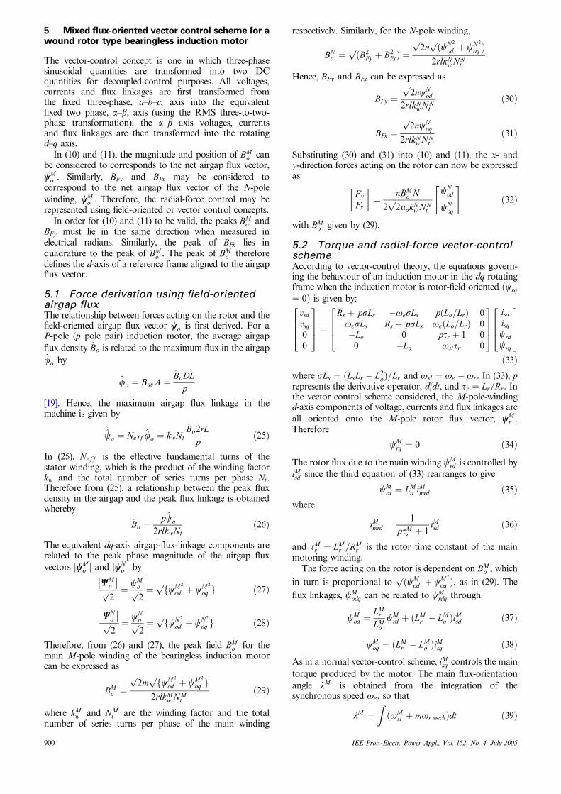
5 Mixed flux-oriented vector control scheme for awound rotor type bearingless induction motor
The vector-control concept is one in which three-phasesinusoidal quantities are transformed into two DCquantities for decoupled-control purposes. All voltages,currents and flux linkages are first transformed fromthe fixed three-phase, a–b–c, axis into the equivalentfixed two phase, a–b, axis (using the RMS three-to-two-phase transformation); the a–b axis voltages, currentsand flux linkages are then transformed into the rotatingd–q axis.
In (10) and (11), the magnitude and position of BMo can
be considered to corresponds to the net airgap flux vector,
wMo . Similarly, BFy and BFx may be considered to
correspond to the net airgap flux vector of the N-pole
winding, wMo . Therefore, the radial-force control may be
represented using field-oriented or vector control concepts.In order for (10) and (11) to be valid, the peaks BM
o andBFy must lie in the same direction when measured inelectrical radians. Similarly, the peak of BFx lies inquadrature to the peak of BM
o . The peak of BMo therefore
defines the d-axis of a reference frame aligned to the airgapflux vector.
5.1 Force derivation using field-orientedairgap fluxThe relationship between forces acting on the rotor and thefield-oriented airgap flux vector wo is first derived. For aP-pole (p pole pair) induction motor, the average airgap
flux density Bo is related to the maximum flux in the airgap
fo by
fo ¼ Bav A ¼ BoDLp
[19]. Hence, the maximum airgap flux linkage in themachine is given by
co ¼ Neff fo ¼ kwNtBo2rL
pð25Þ
In (25), Neff is the effective fundamental turns of thestator winding, which is the product of the winding factorkw and the total number of series turns per phase Nt.Therefore from (25), a relationship between the peak fluxdensity in the airgap and the peak flux linkage is obtainedwhereby
Bo ¼pco
2rlkwNtð26Þ
The equivalent dq-axis airgap-flux-linkage components arerelated to the peak phase magnitude of the airgap flux
vectors jwMo j and jwN
o j byWM
o
�� ��2p ¼ cM
o
2p ¼ f
pcM2
od þ cM2
oq g ð27Þ
WNo
�� ��2p ¼ cN
o
2p ¼ f
pcN2
od þ cN2
oq g ð28Þ
Therefore, from (26) and (27), the peak field BMo for the
main M-pole winding of the bearingless induction motorcan be expressed as
BMo ¼
2p
m fp
cM2
od þ cM2
oq g2rlkM
w N Mt
ð29Þ
where kMw and NM
t are the winding factor and the totalnumber of series turns per phase of the main winding
respectively. Similarly, for the N-pole winding,
BNo ¼ ðp
B2Fy þ B2
FxÞ ¼2p
n ðp
cN2
od þ cN2
oq Þ2rlkN
w N Nt
Hence, BFy and BFx can be expressed as
BFy ¼2p
ncNod
2rlkNw N N
tð30Þ
BFx ¼2p
ncNoq
2rlkNw NN
tð31Þ
Substituting (30) and (31) into (10) and (11), the x- andy-direction forces acting on the rotor can now be expressedas
Fy
Fx
� �¼ pBM
o N
2 2p
mokNw NN
t
cNod
cNoq
" #ð32Þ
with BMo given by (29).
5.2 Torque and radial-force vector-controlschemeAccording to vector-control theory, the equations govern-ing the behaviour of an induction motor in the dq rotatingframe when the induction motor is rotor-field oriented ðcrq
oÞ=Lr and osl ¼ oe � or. In (33), prepresents the derivative operator, d/dt, and tr ¼ Lr=Rr. Inthe vector control scheme considered, the M-pole-windingd-axis components of voltage, currents and flux linkages are
all oriented onto the M-pole rotor flux vector, wMr .
Therefore
cMrq ¼ 0 ð34Þ
The rotor flux due to the main winding cMrd is controlled by
iMsd since the third equation of (33) rearranges to give
cMrd ¼ LM
o iMmrd ð35Þ
where
iMmrd ¼
1
ptMr þ 1
iMsd ð36Þ
and tMr ¼ LM
r =RMr is the rotor time constant of the main
motoring winding.The force acting on the rotor is dependent on BM
o , which
in turn is proportional to ðp
cM2
od þ cM2
oq Þ, as in (29). The
flux linkages, cModq can be related to cM
rdq through
cMod ¼
LMr
LMocM
rd þ ðLMr � LM
o ÞiMsd ð37Þ
cMoq ¼ ðLM
r � LMo ÞiMsq ð38Þ
As in a normal vector-control scheme, iMsq controls the main
torque produced by the motor. The main flux-orientation
angle lM is obtained from the integration of thesynchronous speed oe, so that
lM ¼ZðoM
sl þ mor mechÞdt ð39Þ
900 IEE Proc.-Electr. Power Appl., Vol. 152, No. 4, July 2005
where oMsl is electrical slip speed of the main rotor flux given
by
oMsl ¼
1
tMr iMmrd
iMsq ð40Þ
obtained from the last line of the induction motor equationsin (33).
The d-axis component of voltage, currents and fluxlinkages of the N-pole system is oriented onto the airgap
field vector wMo . The electrical-orientation angle of the
N-pole system lN is therefore displaced to lM by
lN ¼ lM þ tan�1cM
oq
cMod
!ð41Þ
where cMod and cM
oq are as given by (37) and (38),
respectively. Eqn. (41) ensures an airgap field orientation
for the N-pole system whereby cNoq ¼ 0.
In a wound-rotor machine, the rotor has an only an M-pole winding so that no N-pole rotor currents are induced.Hence, the airgap-flux-linkage equation due to the N-polewinding reduces to:
cNodq ¼ LN
o iNsdq ð42Þ
A direct relationship between the forces acting on the rotorand the N-pole stator currents iNsd and iN
sq is obtained
through substitution of (42) into (32):
Fy
Fx
� �¼ pBonLN
o
2 2p
mokNw NN
t
iNsd
iNsq
" #ð43Þ
and the N-pole stator-current references iN�sd and iN�sq can be
determined from F �y and F �x by inverting (43) to give
iN�sd
iN�sq
� �¼ 2 2p
mokNw N N
t
pBonLNo
F �yF �x
" #ð44Þ
In a true bearingless motor, the forces F �y and F �x are
obtained from a position control loop in which the rotor’svertical and horizontal displacements are measured. How-ever, for bearing-relief purposes F �y and F �x may be constant
values set to the rotor weight and zero, respectively.Figure 11 shows the bearing-relief-vector control struc-
ture for a wound-rotor induction-machine configurationwith the mixed flux-oriented scheme. The scheme is ‘mixed’because the variables associated with M-pole system are inthe rotor-flux-frame co-ordinates while those associatedwith the N-pole system are in the frame of the M-pole
PI
PIPl
3-to-2
�risq
isqM
isdN*
isd
vsd
vsqisqN*
isq
isabc
isq
vsq
�sl �e
�r mech
vsabcM*
vsabc
isabc
vsa�
vsa�
isa�
isa�
vsdisd
isdM
isd
�M
�N
�M
m
e j�
e j�
2-to-3PI
PI
3-to-2
equation(40)
2-to-3
∫
e− j�
e− j�
�rdM = Lo
M imrdM
�oqM
�odM equation
(29)
equation(44)
BoM
tan−1
F*y
F*x
equations(37) &(38)
+
+
+
−
−
− −
−M
M
M
M
M*M*
M*
M*
M*
NN
NN*
*
M
N
N
N*N*
N*
Fig. 11 Vector-control scheme for wound-rotor-type bearing-relief induction motor
IEE Proc.-Electr. Power Appl., Vol. 152, No. 4, July 2005 901
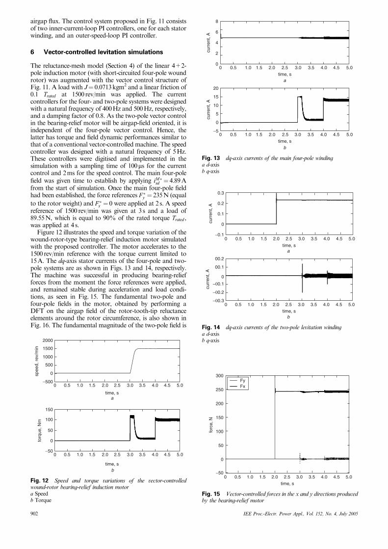
airgap flux. The control system proposed in Fig. 11 consistsof two inner-current-loop PI controllers, one for each statorwinding, and an outer-speed-loop PI controller.
6 Vector-controlled levitation simulations
The reluctance-mesh model (Section 4) of the linear 4+2-pole induction motor (with short-circuited four-pole woundrotor) was augmented with the vector control structure ofFig. 11. A load with J¼ 0.0713kgm2 and a linear friction of0.1 Trated at 1500 rev/min was applied. The currentcontrollers for the four- and two-pole systems were designedwith a natural frequency of 400Hz and 500Hz, respectively,and a damping factor of 0.8. As the two-pole vector controlin the bearing-relief motor will be airgap-field oriented, it isindependent of the four-pole vector control. Hence, thelatter has torque and field dynamic performances similar tothat of a conventional vector-controlled machine. The speedcontroller was designed with a natural frequency of 5Hz.These controllers were digitised and implemented in thesimulation with a sampling time of 100ms for the currentcontrol and 2ms for the speed control. The main four-polefield was given time to establish by applying iM�sd ¼ 4.89Afrom the start of simulation. Once the main four-pole fieldhad been established, the force references F �y ¼ 235N (equal
to the rotor weight) and F �x ¼ 0 were applied at 2 s. A speedreference of 1500 rev/min was given at 3 s and a load of89.55N, which is equal to 90% of the rated torque Trated ,was applied at 4 s.
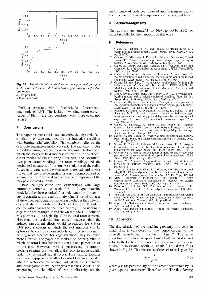
Figure 12 illustrates the speed and torque variation of thewound-rotor-type bearing-relief induction motor simulatedwith the proposed controller. The motor accelerates to the1500 rev/min reference with the torque current limited to15A. The dq-axis stator currents of the four-pole and two-pole systems are as shown in Figs. 13 and 14, respectively.The machine was successful in producing bearing-reliefforces from the moment the force references were applied,and remained stable during acceleration and load condi-tions, as seen in Fig. 15. The fundamental two-pole andfour-pole fields in the motor, obtained by performing aDFT on the airgap field of the rotor-tooth-tip reluctanceelements around the rotor circumference, is also shown inFig. 16. The fundamental magnitude of the two-pole field is
0 0.5 1.0 1.5 2.0 2.5 3.0 3.5 4.0 5.04.5
2000
1500
1000
500
−500
0
atime, s
btime, s
spee
d, r
ev/m
in
0 0.5 1.0 1.5 2.0 2.5 3.0 3.5 4.0 5.04.5
50
100
150
−50
0torq
ue, N
m
Fig. 12 Speed and torque variations of the vector-controlledwound-rotor bearing-relief induction motora Speedb Torque
0 0.5 1.0 2.0 3.0 4.01.5 2.5 3.5 4.5
time, s
5.0
0
−5
5
10
15
20
curr
ent,
A
0 0.5 1.0 2.0 3.0 4.01.5 2.5 3.5 4.5
time, s
5.00
2
4
6
8
curr
ent,
A
a
b
Fig. 13 dq-axis currents of the main four-pole windinga d-axisb q-axis
0time, s
0 0.5 1.0 2.0 3.0 4.01.5 2.5 3.5 4.5
time, s
5.0
0
0
0.3
0.2
0.1
−0.1
curr
ent,
A
00.2
00.1
−00.1
−00.2
−00.3
curr
ent,
A
a
b
0.5 1.0 2.0 3.0 4.01.5 2.5 3.5 4.5 5.0
Fig. 14 dq-axis currents of the two-pole levitation windinga d-axisb q-axis
FyFx
300
250
200
100
150
50
−50
0
0 1.0 2.00.5 1.5 2.5 3.0 4.0 5.03.5 4.5
forc
e, N
time, s
Fig. 15 Vector-controlled forces in the x and y directions producedby the bearing-relief motor
902 IEE Proc.-Electr. Power Appl., Vol. 152, No. 4, July 2005
17mT, as expected, with a four-pole-field fundamentalmagnitude of 0.9T. The levitation-winding stator-currentvalues of Fig. 14 are also consistent with those calculatedusing (44).
7 Conclusions
This paper has presented a system-embedded dynamic-fieldsimulation of cage and wound-rotor induction machineswith bearing-relief capability. This capability relies on thedual-pole bearingless-motor concept. The induction motoris modelled using the dynamic-reluctance-mesh technique inwhich the magnetic-field model is coupled to the electrical-circuit models of the motoring (four-pole) and ‘levitation’(two-pole) stator windings, the rotor windings and themechanical equations of motion. A simulation of the radialforces in a cage machine was also presented and it wasshown that the force-generating process is compromised byleakage effects introduced by the large slip frequency of thetwo-pole induced currents.
These leakages cause field distributions with largeharmonic contents. As such for 4+2-type machinemodelled, the short-circuited four-pole wound-rotor topol-ogy is considered more appropriate. One of the advantagesof the embedded-dynamic-modelling method is that one caneasily study the combined effects of the overall systemcontrol with changes to the machine design. Considering acage rotor, for example, it was shown that the 4+2 solutionwas poor due to the high slip of the induced rotor currents.However, the understanding gained suggests that theinduced slip-current effects would be reduced for 8–6 or10–8 pole selections in which the slot numbers can beoptimised to control leakage reluctances. For such designs,bearing-relief schemes for cage machines may be muchmore effective. The paper has focused on bearing relief inwhich the rotor is not free to move in a plane perpendicularto the axis. However, work is progressing on airgap-meshing schemes that will allow the rotor to move radiallyunder the generated radial forces. This feature, togetherwith an airgap-position feedback-control loop incorporatedinto the vector-control scheme, will allow the simulationand investigation of real bearingless machines. Work is alsoprogressing on the effect of iron nonlinearity on the
performance of both bearing-relief and bearingless induc-tion machines. These developments will be reported later.
8 Acknowledgments
The authors are grateful to Newage AVK SEG ofStamford, UK for their support of this work.
9 References
1 Chiba, A., Rahman, M.A., and Fukao, T.: ‘Radial force in abearingless reluctance motor’, IEEE Trans., 1991, MAG-27, (2),pp. 786–790
2 Oshima, M., Miyazawa, S., Deido, T., Chiba, A., Nakamura, F., andFukao, T.: ‘Characteristics of a permanent magnet type bearinglessmotor’, IEEE Trans. on Ind., 1996, IA-32, (2), pp. 363–370
3 Chiba, A., Power, D.T., and Rahman, M.A.: ‘Analysis of no-loadcharacteristics of a bearingless induction motor’, IEEE Trans., 1995,IA-31, (1), pp. 77–83
4 Chiba, A., Furuichi, R., Aikawa, Y., Takamoto, Y., and Fukao, T.:‘Stable operation of induction-type bearingless motors under loadedconditions’, IEEE Trans., 1997, IA-33, (4), pp. 919–924
5 Osama, M., and Lipo, T.: ‘A magnetic relief scheme for four poleinduction motors’. Proc. 6th Int. Conf. ELECTRIMACS’ 99.Modelling and Simulation of Electric Machines, Converters andSystems, 1999, Vol. 1, pp. I15–21
6 Khoo, S.W.K., Fittro, R.L., and Garvey, S.D.: ‘AC polyphace self-bearing motors with a bridge configured winding’. Proc. 8th Int.Symp. Magnetic Bearings, Mito, Japan, 2002, pp. 47–52
7 Okada, Y., Dejima, K., and Ohishi, T.: ‘Analysis and comparison ofPM synchronous motor and induction motor type magnetic bearing’,IEEE Trans., 1995, IA-31, (5), pp. 1047–1053
8 Nomura, S., Chiba, A., Nakamura, F., Ikeda, K., Fukao, T., andRahman, M.A.: ‘A radial position control of induction typebearingless motor considering phase delay caused by the rotor squirrelcage’. Conf. Rec. Power Conversion Conf., Yokohama, Japan, Apr.1993, pp. 438–443
9 Chiba, A., Miyatake, R., Hara, S., and Fukao, T.: ‘Transfercharacteristics of radial force of induction-type bearingless motorswith four-pole rotor circuits’. Proc. 5th Int. Symp. Magnetic Bearings,Kanazawa, Japan, 1996, pp. 319–325
10 Sch.ob, R., and Bichsel, J.: ‘Vector control of bearingless motors’.Proc. 4th Int. Symp. onMagnetic Bearings, Zurich, Switzerland, Aug.1994, pp. 327–332
11 Suzuki, T., Chiba, A., Rahman, M.A., and Fukao, T.: ‘An air-gap-flux-oriented vector controller for stable operation of bearinglessinduction motors’, IEEE Trans., 2000, IA-36, (4), pp. 1069–1076
12 Ostovic, V.: ‘A method for evaluation of transient and steady stateperformance in saturated squirrel cage induction machines’, IEEETrans., 1986, EC-1, (3), pp. 190–197
13 Ostovic, V.: ‘A simplified approach to magnetic equivalent-circuitmodelling of induction machines’, IEEE Trans., 1988, IA-24, (2),pp. 308–316
14 Sewell, P., Bradley, K.J., Clare, J.C., Wheeler, P.W., Ferrah, A., andMagill, R.: ‘Efficient dynamic models for induction machines’, Int. J.Num. Model. Electron. Netw. Devices Fields, 1999, 12, (6), pp. 449–464
15 Mizia, J., Adamiak, K., Eastham, A.R., and Dawson, G.E.: ‘Finiteelement force calculation: somparison of methods for electricmachine’, IEEE Trans., 1988, MAG-22, (1), pp. 447–450
16 Press, W.H., Teukolsky, S.A., Vetterling, W.T., and Flannery, B.P.:‘Numerical recipes in C++’ (Cambridge University Press, UK, 2002,2nd edn.), p. 383
17 Van Der Vorst, H.A.: ‘Bi-CGSTAB: A fast and smoothly convergingvariant of Bi-CG for the solution of nonsymmetric linear systems’,SIAM J. Sci. Stat. Comput., 1992, 13, pp. 631–644
18 Alger, P.L.: ‘Induction machines’ (Gordon and Breach Publishers,1995, 2nd edn.), p. 81
19 Alger, P.L.: ‘Induction machines’ (Gordon and Breach Publishers,1995, 2nd edn.), p. 94
10 Appendix
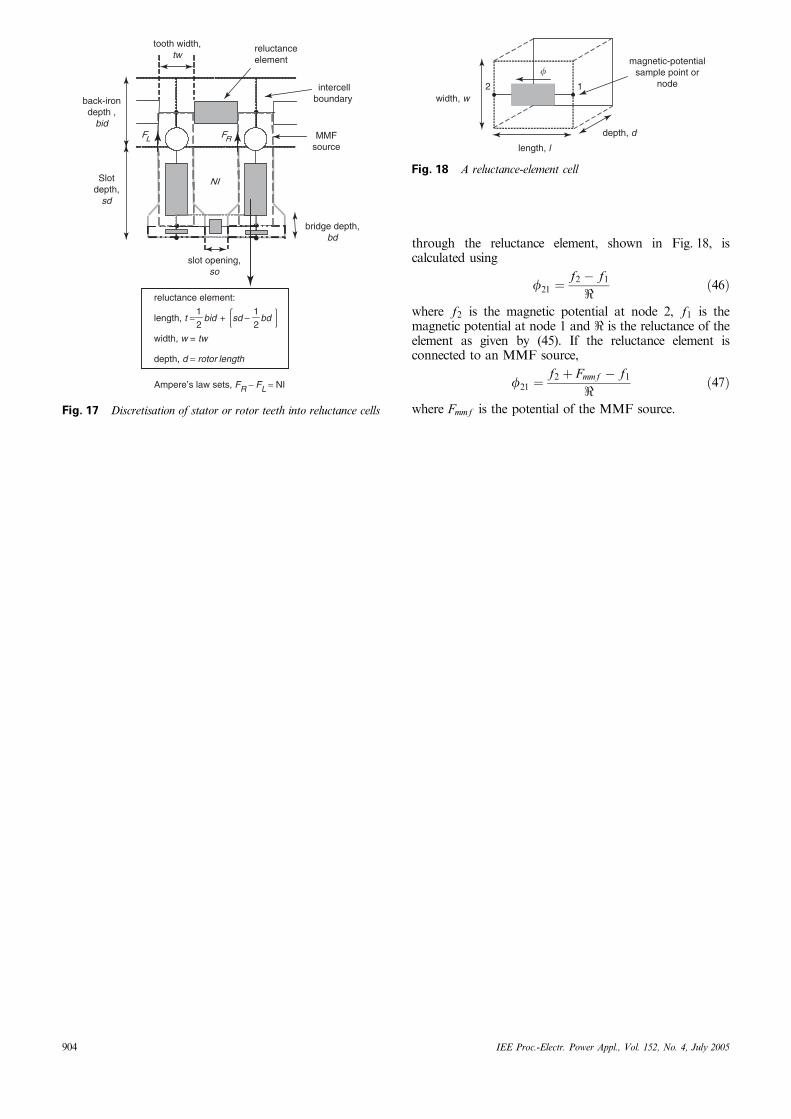
The discretisation of the machine geometry into cells, inwhich flux is considered to flow perpendicular to theintercell boundaries, is shown in Fig. 17. The samediscretisation method is applied onto both the stator androtor teeth. Each cell is represented by a reluctance elementhaving an associated width w, length l, and depth d, asshown in Fig. 18. The reluctance of each element is given by
< ¼ lmwd
ð45Þ
where m is the permeability of the element determined by itsgiven type, i.e. ‘nonlinear’, ‘linear’ or ‘air’. The flux flowing
0.025
0.020
0.015
0.010
0.005
00 0.5 1.0 2.0 3.0 4.01.5 2.5 3.5 5.04.5
flux
dens
ity, T
flux
dens
ity, T
time, s
0.8
0.6
0.4
0.2
0
1.0
time, s
a
b
0 0.5 1.0 2.0 3.0 4.01.5 2.5 3.5 5.04.5
Fig. 16 Magnitude of the fundamental two-pole and four-polefields of the vector-controlled wound-rotor-type bearing-relief induc-tion motora Two-pole fieldb Four-pole field
IEE Proc.-Electr. Power Appl., Vol. 152, No. 4, July 2005 903
through the reluctance element, shown in Fig. 18, iscalculated using
f21 ¼f2 � f1
< ð46Þ
where f2 is the magnetic potential at node 2, f1 is themagnetic potential at node 1 and < is the reluctance of theelement as given by (45). If the reluctance element isconnected to an MMF source,
f21 ¼f2 þ Fmmf � f1
< ð47Þ
where Fmmf is the potential of the MMF source.
FL FR
NI
back-irondepth ,
bid
Slotdepth,
sd
slot opening,so
bridge depth,bd
MMFsource
intercellboundary
reluctanceelement
tooth width,tw
reluctance element:
length, t = −+ bdsdbid21
21
width, w = tw
depth, d = rotor length
Ampere’s law sets, FR − FL = NI
Fig. 17 Discretisation of stator or rotor teeth into reluctance cells
2 1
magnetic-potentialsample point or
node
depth, d
length, l
width, w
�
Fig. 18 A reluctance-element cell
904 IEE Proc.-Electr. Power Appl., Vol. 152, No. 4, July 2005