Hindawi Publishing CorporationInternational Journal of Reconfigurable ComputingVolume 2008, Article ID 901328, 10 pagesdoi:10.1155/2008/901328
Research Article
Dynamic Hardware Development
Stephen Craven1 and Peter Athanas2
1 Department of Electrical Engineering, The University of Tennessee at Chattanooga, Chattanooga, TN 37403, USA2 Bradley Department of Electrical and Computer Engineering, Virginia Polytechnic and State University,Blacksburg, VA 24061, USA
Correspondence should be addressed to Stephen Craven, [email protected]
Received 31 March 2008; Accepted 12 August 2008
Recommended by Michael Hubner
Applications that leverage the dynamic partial reconfigurability of modern FPGAs are few, owing in large part to the lack of suitabletools and techniques to create them. While the trend in digital design is towards higher levels of design abstractions, forgoinghardware description languages in some cases for high-level languages, the development of a reconfigurable design requiresdevelopers to work at a low level and contend with many poorly documented architecture-specific aspects. This paper discusses thecreation of a high-level development environment for reconfigurable designs that leverage an existing high-level synthesis tool toenable the design, simulation, and implementation of dynamically reconfigurable hardware solely from a specification written inC. Unlike previous attempts, this approach encompasses the entirety of design and implementation, enables self-re-configurationthrough an embedded controller, and inherently handles partial reconfiguration. Benchmarking numbers are provided, whichvalidate the productivity enhancements this approach provides.
Field-programmable gate arrays (FPGAs) are a class ofintegrated circuits that can be reprogrammed numeroustimes after manufacture to implement arbitrary digitalcircuits. While FPGAs always lag custom application-specificICs (ASICs) in performance, the significantly reduced non-re-occurring engineering costs make FPGAs attractive for avariety of applications. However, with very few exceptions, anFPGA in a deployed design implements a single static design,behaving exactly as if it were a fixed-function ASIC.
The ability to reconfigure itself in a deployed productoffers FPGAs a distinct advantage over ASICs. Whereas anASIC must allocate area to implement every digital circuitthe application requires, regardless of how infrequently itis actually exercised, an FPGA only need be sized largeenough to support the circuits being active at any onetime. The research community has demonstrated the benefitsof swapping circuits in and out of an FPGA in suchdiverse applications as image detection [1], gene sequencing[2], video processing [3], network applications [4], andinstruction set extension [5].
Vendor and tool support for the dynamic partial recon-figuration (PR) of an FPGA has suffered from severe limi-tations in the past. PR design flows were poorly supportedand frequently broken. Device configuration architecturesrequired that an entire configuration column be loaded justto change a single bit in the FPGA configuration. Self-re-configuration, through an internal configuration access port(ICAP), was limited to high-end devices, raising the cost ofPR designs.
Recently, the PR landscape has experienced a change,driven in part by the growing importance of software definedradio (SDR), with its dynamic creation of radio waveforms.As the throughput requirements of SDR are impossible tomeet with a processor and the configurability to implementarbitrary waveforms is beyond the capabilities of ASICs,the PR abilities of FPGAs are finally gaining tool support[6, 7]. The newer device families feature a configurationarchitecture that is more granular, increasing the speed andflexibility of PR [8]. Furthermore, PR capabilities have beenextended to low-cost device families [9].
In spite of these trends, much work remains beforePR design becomes an accepted practice. To develop
2 International Journal of Reconfigurable Computing
a PR application using current tools, a designer must learnthe intricacies of the target architecture and nuances ofunfamiliar design flows. Lacking models and tools to abstractaway the low-level specifics of each different architecture,every porting of a PR application to a different devicerequires that the design process start anew. Simulation of aPR design before implementation must be forgone, owingto a lack of simulator support, complicating verification anddebugging.
Concurrent with the changes in the PR landscape hasbeen a push towards electronic system-level (ESL) design.ESL design involves raising the level of abstraction that adesigner sees from the register transfer level (RTL) to some-thing higher than what traditional hardware descriptionlanguages (HDLs) provide [10]. The research community hasexperimented with high-level languages (HLLs) to lift theabstraction level [11], and their results are paying off witha variety of commercial ESL tools now available [12]. Designspecifications can now be captured in a multitude of formatsfrom graphical [13] to C [14], and automatically converted tosynthesizable HDL by commercial high-level synthesis (HLS)tools.
Recognizing the potential for HLS to drastically reducethe complexity of PR design, several researchers havedescribed development environments utilizing some formof high-level design capture specifically tailored to PRdesign [15–17]. Notable limitations in these projects, though,hinder their ability to take advantage of recent trends in con-figurable computing. The reliance of many of these projectson an external host hinders development of embeddedapplications and ignores embedded processor capabilitiesof modern FPGAs. The use of outdated design entrytechniques, such as JBits [18], shackles several projects toolder architectures.
This paper describes a new approach to PR applica-tion development that leverages a commercial HLS tool,integrates embedded processors, and provides models ofcommunication and reconfiguration. Previous publicationshave described the methodology [19] and the languageextensions to an HLS toolset [20]. This paper focuses onthe implementation and testing of the development flow,providing design and productivity results that validate thisapproach.
Section 2 provides an overview of previous attempts toraise the level of abstraction in PR design. An overviewof the approach of this paper is presented in Section 3,with Section 4 detailing the implementation of applicationsand providing benchmarking results. Finally, conclusions arediscussed in Section 5.
2. Background
To address the difficulties in applying traditional designmethodologies to PR applications, several researchers haveproposed or implemented new methodologies targeting therequirements of PR hardware.
Janus [16] was an early effort at a unified PR appli-cation development environment centered around Java.Software for the host PC was written in Java, while the
hardware for the multi-FPGA system was created in thesame environment from JHDL, a Java-based structuralhardware description language. Janus was developed underthe coprocessor paradigm where the FPGA is essentially aslave to an external host processor. Partial reconfigurationand dynamic scheduling are not supported.
The PaDReH framework [21] focuses solely on hardwaredevelopment, defining an open development flow permit-ting multiple methods of design capture, simulation, andpartitioning to be used. Partial bitstream generation occurswithin the Xilinx modular design flow, which is the onlyfully specified step in the framework. Little is provided to thedesigner in terms of tools or abstractions.
Synthesis and partitioning for adaptive reconfigurablecomputing systems (SPARCSs) [22] start with a behav-ioral VHDL description of the application separated intotasks communicating through shared memory or directconnections. Temporal and spatial scheduling occurs acrossmultiple FPGAs. A high-level synthesis tool converts thebehavioral description to RTL that is then processed withtraditional tools.
The Institute for Software Integrated Systems (ISIS)describes a prototype model-integrated design environmentfor dataflow applications [23]. ISIS focuses on constraint-driven development and verification from a model-basedapproach. Tools automatically apply user-specified con-straints to prune the design space. The development envi-ronment targets board-level designs comprised of heteroge-neous computing elements (FPGAs, DSPs, processors, etc.),limiting the utility for FPGA-centric applications.
Recent work from Imperial College London definesabstractions of low-level details with an HLL-based approachto PR application development [15]. A modified form of C(RT-C) captures the design behavior at a high level, includingconfiguration control. The RT-C is then translated intoHandel-C [24], a commercial C-to-gates synthesis tool. Animplementation flow generates the required configurationfiles, with configuration management handled by a hostprocessor. The implementation flow, however, is based onJBits and therefore is limited to older architectures. Also, amanual translation is required to go from the Handel-C-generated HDL to JBits, and the resulting design is shackledto a host processor.
Brigham Young University developed a JHDL-basedreconfigurable computing application framework (RCAF)with the distinguishing feature that the framework, con-sisting of control, communication, and debugging aids,is deployed in the finished product [25]. The frameworkassumes a tight integration of the FPGA with a host processorrunning a controlling Java programme. This framework doeslittle to facilitate the capture of configuration management orthe incorporation of embedded processors.
The Caronte PR framework defines a high-level develop-ment environment targeting coprocessor applications [26].Simulation of PR is possible via SystemC, with design entryvia HDLs or Impulse C [27]. Caronte’s use of Impulse Cdiffers from the work presented in this paper in that Carontemerely uses Impulse C to produce HDL and not to capturethe totality of the application including the configuration
International Journal of Reconfigurable Computing 3
control. The bus-based communication of Caronte limits itsapplicability to streaming applications.
In addition to the projects described above, severalresearchers have explored the problem without producinga prototype design environment. Eisenring and Platzner’sPR framework [28] describes a tool-independent design andimplementation methodology in generic terms. Berkley’sStream Computations Organized for Reconfigurable Exe-cution (SCORE) project [29] proposes a new FPGA-likearchitecture leveraging hardware pages to permit location-independent reconfiguration. While promising, no hardwarehas been produced.
These previous projects, summarized in Table 1, areeach limited in important ways. Most assume a modelof external configuration control, mandating the use of ahost processor. For embedded application, this requirementis generally prohibitive. Many do not enable the use ofpartial reconfiguration. It is also interesting to note that noproject has been extended, by its authors or others, since itsinitial implementation. This is perhaps in part due to thetight coupling of many of these frameworks to a specificarchitecture or design capture tool.
3. Approach
The goal of this project is to significantly reduce the effortrequired to deploy PR designs. To this end, a high-leveldevelopment flow has been implemented that permits PRdesigns to be specified in C. Models of communication,computation, and reconfiguration have been defined thatsimplify design of streaming applications.
The development flow consists of a frontend, archi-tecture-agnostic design flow, and a backend architecture-specific implementation flow. The design flow leverages anexisting commercial HLS tool, modified to enable the captureand simulation of PR designs. By utilizing a commercialESL tool, this work avoids the pitfalls of previous projectsthat relied heavily on outdated and unsupported tools suchas JBits. The implementation flow is completely automated,encompassing floorplanning of the PR regions, insertion of aconfiguration controller, creation of the partial configurationbitstreams, and packaging of the configuration bitstreams fordeployment.
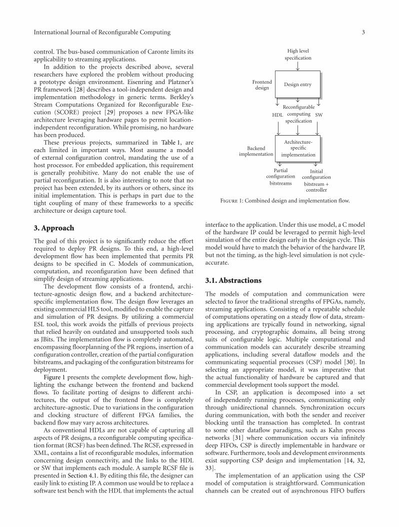
Figure 1 presents the complete development flow, high-lighting the exchange between the frontend and backendflows. To facilitate porting of designs to different archi-tectures, the output of the frontend flow is completelyarchitecture-agnostic. Due to variations in the configurationand clocking structure of different FPGA families, thebackend flow may vary across architectures.
As conventional HDLs are not capable of capturing allaspects of PR designs, a reconfigurable computing specifica-tion format (RCSF) has been defined. The RCSF, expressed inXML, contains a list of reconfigurable modules, informationconcerning design connectivity, and the links to the HDLor SW that implements each module. A sample RCSF file ispresented in Section 4.1. By editing this file, the designer caneasily link to existing IP. A common use would be to replace asoftware test bench with the HDL that implements the actual
High levelspecification
Design entryFrontenddesign
Architecture-specific
implementation
Reconfigurablecomputing
specificationHDL SW
Backendimplementation
Partialconfiguration
bitstreams
Initialconfigurationbitstream +controller
Figure 1: Combined design and implementation flow.
interface to the application. Under this use model, a C modelof the hardware IP could be leveraged to permit high-levelsimulation of the entire design early in the design cycle. Thismodel would have to match the behavior of the hardware IP,but not the timing, as the high-level simulation is not cycle-accurate.
3.1. Abstractions
The models of computation and communication wereselected to favor the traditional strengths of FPGAs, namely,streaming applications. Consisting of a repeatable scheduleof computations operating on a steady flow of data, stream-ing applications are typically found in networking, signalprocessing, and cryptographic domains, all being strongsuits of configurable logic. Multiple computational andcommunication models can accurately describe streamingapplications, including several dataflow models and thecommunicating sequential processes (CSP) model [30]. Inselecting an appropriate model, it was imperative thatthe actual functionality of hardware be captured and thatcommercial development tools support the model.
In CSP, an application is decomposed into a setof independently running processes, communicating onlythrough unidirectional channels. Synchronization occursduring communication, with both the sender and receiverblocking until the transaction has completed. In contrastto some other dataflow paradigms, such as Kahn processnetworks [31] where communication occurs via infinitelydeep FIFOs, CSP is directly implementable in hardware orsoftware. Furthermore, tools and development environmentsexist supporting CSP design and implementation [14, 32,33].
The implementation of an application using the CSPmodel of computation is straightforward. Communicationchannels can be created out of asynchronous FIFO buffers
4 International Journal of Reconfigurable Computing
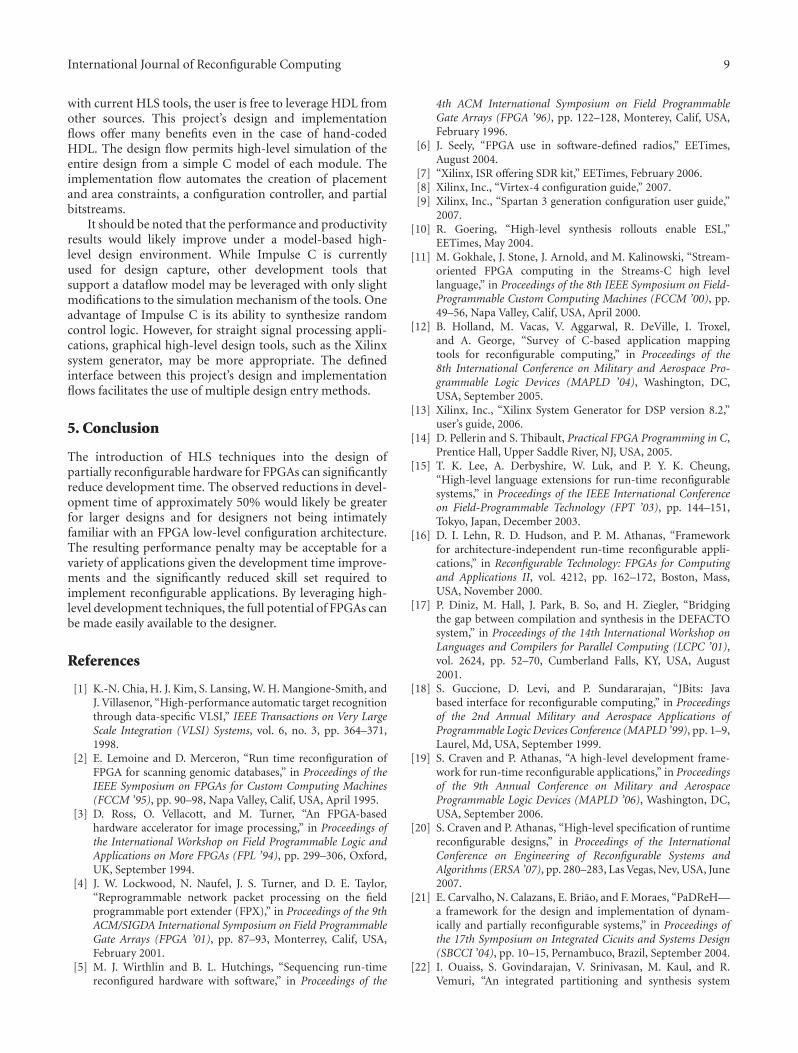
Table 1: Previous PR development environments.
Project Design entry Model of computation Architecture Limitations
Imperial College RT-C Dataflow Limited by JBitsRequires host
Manual translation
Caronte Various Coprocessor Embedded proc Limited automation
with minimal communication overhead. The FIFO-basedcommunication permits easy integration with embeddedprocessors as many Xilinx embedded processors featurefast simplex link (FSL) interfaces that are nothing morethan asynchronous FIFO buffers linking the processor toperipherals [34].
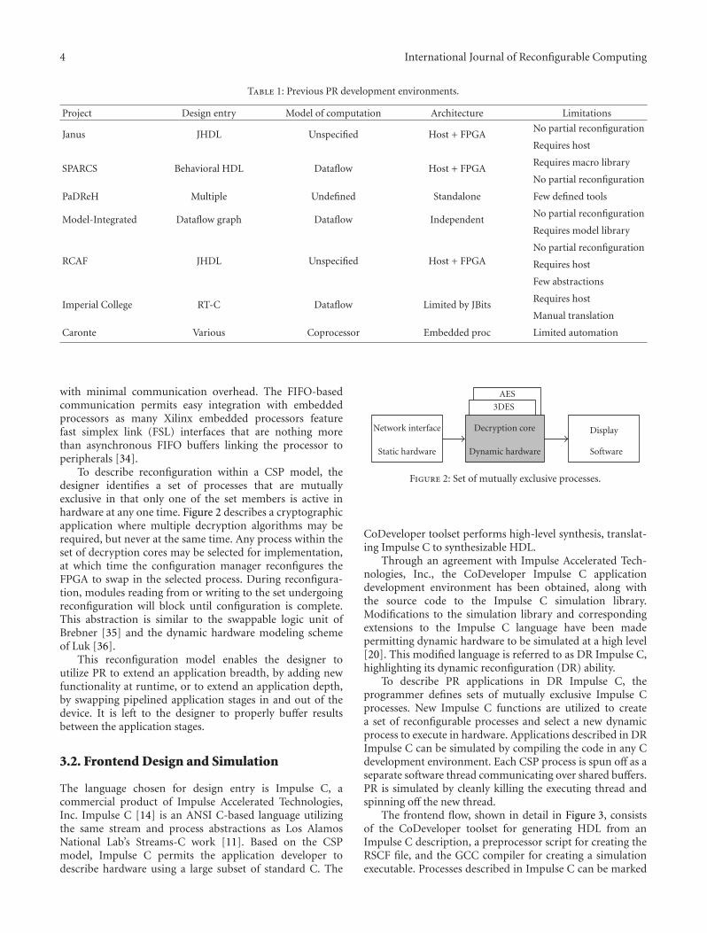
To describe reconfiguration within a CSP model, thedesigner identifies a set of processes that are mutuallyexclusive in that only one of the set members is active inhardware at any one time. Figure 2 describes a cryptographicapplication where multiple decryption algorithms may berequired, but never at the same time. Any process within theset of decryption cores may be selected for implementation,at which time the configuration manager reconfigures theFPGA to swap in the selected process. During reconfigura-tion, modules reading from or writing to the set undergoingreconfiguration will block until configuration is complete.This abstraction is similar to the swappable logic unit ofBrebner [35] and the dynamic hardware modeling schemeof Luk [36].
This reconfiguration model enables the designer toutilize PR to extend an application breadth, by adding newfunctionality at runtime, or to extend an application depth,by swapping pipelined application stages in and out of thedevice. It is left to the designer to properly buffer resultsbetween the application stages.
3.2. Frontend Design and Simulation
The language chosen for design entry is Impulse C, acommercial product of Impulse Accelerated Technologies,Inc. Impulse C [14] is an ANSI C-based language utilizingthe same stream and process abstractions as Los AlamosNational Lab’s Streams-C work [11]. Based on the CSPmodel, Impulse C permits the application developer todescribe hardware using a large subset of standard C. The
Network interface
Static hardware
Decryption core
Dynamic hardware
AES
3DES
Display
Software
Figure 2: Set of mutually exclusive processes.
CoDeveloper toolset performs high-level synthesis, translat-ing Impulse C to synthesizable HDL.
Through an agreement with Impulse Accelerated Tech-nologies, Inc., the CoDeveloper Impulse C applicationdevelopment environment has been obtained, along withthe source code to the Impulse C simulation library.Modifications to the simulation library and correspondingextensions to the Impulse C language have been madepermitting dynamic hardware to be simulated at a high level[20]. This modified language is referred to as DR Impulse C,highlighting its dynamic reconfiguration (DR) ability.
To describe PR applications in DR Impulse C, theprogrammer defines sets of mutually exclusive Impulse Cprocesses. New Impulse C functions are utilized to createa set of reconfigurable processes and select a new dynamicprocess to execute in hardware. Applications described in DRImpulse C can be simulated by compiling the code in any Cdevelopment environment. Each CSP process is spun off as aseparate software thread communicating over shared buffers.PR is simulated by cleanly killing the executing thread andspinning off the new thread.
The frontend flow, shown in detail in Figure 3, consistsof the CoDeveloper toolset for generating HDL from anImpulse C description, a preprocessor script for creating theRSCF file, and the GCC compiler for creating a simulationexecutable. Processes described in Impulse C can be marked
International Journal of Reconfigurable Computing 5
Preprocess
CoDeveloper(impulse accelerated)
DR impulse C
CoDeveloperprojects
Simulationlibrary
gcc(GNU)
XML HDL C Simulationexecutable
To backend flow
Tools created by this project
Commercial tools
Fron
ten
d
Figure 3: Frontend tool flow.
for hardware implementation, in which the CoDevelopertools convert the corresponding code to an HDL, or canbe targeted to an embedded processor. The implementationflow handles the mapping of software processes to specificprocessors available on the target platform.
3.3. Backend Implementation
The architecture-specific implementation flow accepts theRCSF file, HDL modules, and C code from the frontend. Inaddition, a board support package (BSP) must be specified,supplying all the platform-specific information required toproduce a deployable design. The implementation tool flow,shown in Figure 4, integrates tools automating placement,HDL generation, and clock creation.
The postprocess tool parses the RCSF and BSP, generat-ing a top-level Verilog wrapper that instantiates each modulein the design, along with the PR control modules, MicroBlazecontroller, and clocking structure. The Floorplanner utilityis responsible for creating area constraints for each recon-figurable region of the FPGA. This tool accepts as input alist of the resource requirements of each set and a list ofkeep-out regions. The keep-out regions correspond to areasof the FPGA that must be available for peripherals or softprocessors, such as regions near critical I/Os. In keeping withother FPGA floorplanning projects [37–39], Floorplanneruses a simulated annealing algorithm to find a near optimalminimum of a cost function.
Unlike most previous works, Floorplanner is knowledge-able of the device configuration architecture, and attempts tofind placements that minimize reconfiguration overhead. Forthe Xilinx Virtex-II and Virtex-II Pro architectures, whereconfiguration frames run the entire height of the device, thisinvolves finding a solution that has a high aspect ratio (heightversus width) to use as much of the configuration frameas possible for the reconfigurable module. In the Virtex-4 architectures, where configuration frames are 16 CLBs
Xilinx early accesspartial reconfiguration flow
Floorplanner BusMacroHelper
Postprocess
Board supportpackage
Constraintsfile
Partialbitstreams
RCSF
gcc(GNU)
Top-levelVerilog
CELF
HDL
CreateLUT
Memoryimage
Initialbitstream
Tools created by this project
Tools modified by this project
Commercial tools
Figure 4: Backend tool flow.
tall, Floorplanner places all modules on configuration frameedges.
Floorplanner starts by first populating a list of moduleplacements, called realizations. All possible realizations areconsidered in the creation of this list, with placements thatare overly wasteful of resources being removed. Once a list ofacceptable placements has been created, simulated annealingis performed to minimize the cost function:
Module overlap, contained in overlap as the sum of alloverlapping CLBs, is weighted orders of magnitude higherin the cost function to ensure that no two PR regions willoverlap. aspectError penalizes the placements for having apoor aspect ratio with the ideal aspect ratio being dependenton the architecture. Higher ideal aspect ratios are used forthe Virtex-II families to minimize reconfiguration overhead.waste is a measure of extra resources within the placementthat will not be utilized on the device. The distancevariable represents the total distance between reconfigurableregions, and it is used to minimize routing delays betweenreconfigurable regions.
Producing partial configuration bitstreams currentlyrequires an Xilinx-supplied patch to the standard XilinxISE toolset. Among other changes, this patch constrainsthe router to keep routes inside a reconfigurable region.These modified tools make up the Xilinx early access PR(EAPR) flow. The EAPR flow requires that special connectionpoints, called bus macros, surround reconfigurable modules,providing a stable connection point to the static hardware.
6 International Journal of Reconfigurable Computing
AMdemod
Externalmemory
FMbitfile
AMbitfile
Lookuptable
Bus macroenable
PRcontrol
Microblaze
swProc
UART
ICAP
bb
I/O Clock ADC
PR reset
FilteredfirProc
To modules
DCMs ADCI/F
rf
FPGA
FSL
Bus macro
Control/clock
Figure 5: Final design implementation.
BusMacroHelper is a tool created for a related project thatautomatically inserts and places bus macros.
The CreateLUT tool creates a binary look-up table(LUT) that lists the size and location in memory of eachpartial bitstream enabling the configuration controller tofind the desired partial bitstream. Additionally, the scriptconcatenates the LUT and the partial bitstreams together intoa single memory image to facilitate the automated downloadof the application to an FPGA.
Figure 5 presents an example implementation of a simpleSDR application that may switch demodulation schemes.Several important aspects of this project are evident in thefigure. The PR module AM Demod has been area-constrainedto a specific location of the FPGA by the Floorplanner tool.All non-re-configurable modules are unconstrained, permit-ting the Xilinx tools to choose their optimum locations.All nonclock signals crossing the boundary between thestatic and PR regions must pass through a bus macro. Asreconfiguration leaves the logic internal to a PR region inan undefined state, to stop the internal logic from producingrandom outputs that affect the rest of the system, the busmacro on the output of a PR region can be disabled. The toolflow automatically creates a PR control module for each PRregion that disables the bus macros before reconfigurationand places any newly reconfigured module into a knowngood state by toggling the module reset line. Control ofpartial reconfiguration is handled by a MicroBlaze-basedsystem running the user control code.
The CSP model permits each process to run at its ownspeed. To replicate this in hardware, each process receives itsown clock, subject to resource availability. The FSL connec-tions between processes are implemented as asynchronousFIFOs to enable cross-clock domain communication. Theclocking structure is automatically generated using timingestimates from the synthesis tool.
4. Results
A video processing application, representative of streamingapplications that benefit from PR, is described in this sectionfollowed by a comparison of the results obtained withthis development flow and the results obtained manuallyfollowing the Xilinx EAPR flow [40].
4.1. Application development
A video processing demonstration has been implementedusing this development flow in which a video stream isfiltered in real time with one of several filters. A separatefilter acts on each of the three colors (red, green, and blue)and each can be independently reconfigured to implementan edge detector, a median image filter, or a pass-through.The edge detector and median image filter operate on a 5× 5window of pixels. The application forgoes a full frame buffer,using a separate columns process to buffer five lines of pixels,presenting a column of five pixels to the filters.
The filters and control logic are all described in DRImpulse C. For high-level simulation, separate test processesare defined that load an input image from a Windows Bitmap(BMP) file and translate filters’ outputs into a BMP, as shownin Figure 6. The filtered output images in Figure 6 wereproduced by this Impulse C simulation.
Before implementation, the application RCSF is editedto replace these Impulse C test benches with the interfacelogic for the video card and video DAC, which are a part ofthe BSP of the Xilinx Virtex-II Pro XUP development board.This edit involves the modification of only eight lines of XMLcode. The original RCSF file is shown in Figure 7. Each CSPprocess is linked to an implementation folder containing theHDL description. Connectivity is expressed by associatingeach port to a stream.
The implemented design (the layout of which is seen inFigure 8) encompasses 63% of an Xilinx xc2vp30. The filtersoperate at 57 MHz, sufficiently fast to support the incoming640 × 480 video stream at 60 Hz. If implemented as a staticdesign, the hardware would have to include nine separatefilters, that is, three filters for each of the three colors.The total area required by all nine filters would be 1707slices. Partial reconfiguration reduces the area requirementsto three instances of the largest filter, consuming 1328 slicesacross three reconfigurable regions, thus resulting in an areasaving of 379 slices due to using PR. Any additional filtersadded to the system would increase this area saving.
4.2. Benchmarks
To quantify the advantages and disadvantages of the high-level development environment, a set of applications wasimplemented in this environment and compared to imple-mentations made following the Xilinx EAPR flow. To moreaccurately simulate real-world design practices, the XilinxEAPR flow was scripted following the PR documentation[40]. All designs were created by an experienced hardwaredesigner familiar with the Xilinx configuration architectureand EAPR flow. Note that the results presented below do
International Journal of Reconfigurable Computing 7
Reconfigurablefilter
Columns
BlueGreen
Red
Producer Consumer
BMP file BMP files
Figure 6: Video processing application.
Figure 7: RCSF file for simulated video processing design.
BlueGreenRed
Microblaze
Video controller
Figure 8: Floorplan of video processing implementation in anXilinx xc2vp30.
not take into account the reduced skill set required by thehigh-level development environment. While some level ofhardware experience is still required to create an applicationin DR Impulse C, it is significantly less than the low-levelarchitecture-specific knowledge needed to follow the XilinxEAPR flow.
The first application involved a reconfigurable coproces-sor for an embedded MicroBlaze processor. This coprocessor,attached via an FSL interface, can be reconfigured toimplement either a 32-bit integer divider or an integersquare-root function. The descriptions for both functionswere obtained from existing IP using the Xilinx Coregentool and the OpenCores internet IP repository, in the caseof the EAPR flow, and using example code provided withthe Impulse C tools, in the case of this project’s developmentenvironment.
The development time for both environments, from ini-tial design description to working hardware implementation,was recorded. The PR region of the Xilinx EAPR flow washand-placed, and it is 36% smaller than the Impulse C-basedapproach, owing to inefficiencies in HLS and automatedfloorplanning. Table 2 presents area and performance resultsat the module level. The Impulse C-generated divider com-pares well with the OpenCores divider, while the Coregensquare-root function is significantly smaller than the ImpulseC-generated module. The Impulse C-generated square-rootfunction has a latency that is data-dependent. It should benoted that this high-level development environment can useexisting IP and is not limited to Impulse C-created hardwarethough currently the implementation flow only supports IPwith an FSL interface.
As presented in Table 3 for the integrated coproces-sor application, the high-level development environmentincurred a 71% penalty in average throughput and an8% overall area penalty when compared to a manualimplementation in the Xilinx EAPR flow. This throughputmetric averages the best- and worst-case throughputs forthe divider and square-root modules. The manual EAPRimplementation ran the coprocessor at the system 100 MHzclock rate. The high-level development environment ran thecoprocessor at 80% of the synthesis tool estimated clockrate for the slowest coprocess module. The performancepenalty could be reduced by leveraging existing IP insteadof using Impulse C-generated HDL. Additional gains arepossible by dynamically modifying the clock rate of thecoprocessor instead of running all coprocessors at the speed
8 International Journal of Reconfigurable Computing
Table 2: Coprocessor module performance benchmarks in an Xilinx xc2vp30.
ModuleArea Speed Throughput
(slices/BRAMs/BMults) (MHz) (ops/sec)
Divider (Impulse C) 258/0/0 134 3.8 (106)
Divider (OpenCores) 159/0/0 123 3.4 (106)
Square root (Impulse C) 760/1/9 56 0.7 (106)–4.7 (106)
of the slowest. The small area penalty is due to the superiorityof hand-placed designs.
The high-level development approach netted a 57%reduction in overall development time, seen in Table 4. Thefrontend number indicates the time required to create thedesign description, whether in DR Impulse C or Verilog. Thebackend number represents the time required to take thedesign description through implementation, and includesany hardware debugging. While the DR Impulse C designbested the Verilog design for each metric, the majority of theproductivity improvement came from the frontend design.Even with the EAPR flow leveraging existing IP, the timerequired to integrate this IP into a design was significantlygreater than the time required to describe the application inImpulse C.
Cryptographic hash functions were used as a secondbenchmarking application. A reconfigurable region on theFPGA could be configured for either the MD5 or the SHA-1 standard. The hash functions were created from scratchusing both Impulse C and Verilog. Area and performancenumbers for each function are shown in Table 5. TheVerilog-described SHA-1 consumed 12% more slices thanthe Impulse C design owing to the use of five independentmemories to permit simultaneous access to the message data.This approach increases throughput at the expense of area.Had area been of primary concern, a Verilog design wouldhave been smaller than the Impulse C-created hardware.The Impulse C MD5 and SHA-1 cores underperformed theVerilog cores by 39% and 63%, respectively.
Table 6 presents the performance results with the crypto-graphic modules integrating into the reconfiguration appli-cation. The high-level development environment imparts a
Table 5: Cryptographic module performance benchmarks in anXilinx xc2vp30.
24% area penalty and a 48% performance penalty, comparedto the conventional Verilog design.
The productivity advantage of the high-level develop-ment environment was hampered in this application by abug in the Impulse C-generated hardware, as seen in Table 7.The time spent resolving this issue resulted in a 28% greaterfrontend design time for the high-level development envi-ronment than that for a Verilog-created design. If the MD5design time was removed from consideration, the frontenddesign times for the high-level and conventional approachesare 1 and 2.2 hours, respectively. This 120% frontend designtime improvement is more in line with the coprocessorproductivity results. If the MD5 design and debug timeare considered, the total development improvement of thehigh-level approach is 10%, while if the MD5 design timeis excluded from both designs, the high-level productivityimprovement increases to 49%, approximating the results forthe coprocessor application.
While the performance and area results obtained fromthe HLS tool may limit its applicability to high-performanceapplications, this does not negate the utility of the presenteddynamic hardware development environment. For designswith timing or area constraints that cannot easily be met
International Journal of Reconfigurable Computing 9
with current HLS tools, the user is free to leverage HDL fromother sources. This project’s design and implementationflows offer many benefits even in the case of hand-codedHDL. The design flow permits high-level simulation of theentire design from a simple C model of each module. Theimplementation flow automates the creation of placementand area constraints, a configuration controller, and partialbitstreams.
It should be noted that the performance and productivityresults would likely improve under a model-based high-level design environment. While Impulse C is currentlyused for design capture, other development tools thatsupport a dataflow model may be leveraged with only slightmodifications to the simulation mechanism of the tools. Oneadvantage of Impulse C is its ability to synthesize randomcontrol logic. However, for straight signal processing appli-cations, graphical high-level design tools, such as the Xilinxsystem generator, may be more appropriate. The definedinterface between this project’s design and implementationflows facilitates the use of multiple design entry methods.
5. Conclusion
The introduction of HLS techniques into the design ofpartially reconfigurable hardware for FPGAs can significantlyreduce development time. The observed reductions in devel-opment time of approximately 50% would likely be greaterfor larger designs and for designers not being intimatelyfamiliar with an FPGA low-level configuration architecture.The resulting performance penalty may be acceptable for avariety of applications given the development time improve-ments and the significantly reduced skill set required toimplement reconfigurable applications. By leveraging high-level development techniques, the full potential of FPGAs canbe made easily available to the designer.
References
[1] K.-N. Chia, H. J. Kim, S. Lansing, W. H. Mangione-Smith, andJ. Villasenor, “High-performance automatic target recognitionthrough data-specific VLSI,” IEEE Transactions on Very LargeScale Integration (VLSI) Systems, vol. 6, no. 3, pp. 364–371,1998.
[2] E. Lemoine and D. Merceron, “Run time reconfiguration ofFPGA for scanning genomic databases,” in Proceedings of theIEEE Symposium on FPGAs for Custom Computing Machines(FCCM ’95), pp. 90–98, Napa Valley, Calif, USA, April 1995.
[3] D. Ross, O. Vellacott, and M. Turner, “An FPGA-basedhardware accelerator for image processing,” in Proceedings ofthe International Workshop on Field Programmable Logic andApplications on More FPGAs (FPL ’94), pp. 299–306, Oxford,UK, September 1994.
[4] J. W. Lockwood, N. Naufel, J. S. Turner, and D. E. Taylor,“Reprogrammable network packet processing on the fieldprogrammable port extender (FPX),” in Proceedings of the 9thACM/SIGDA International Symposium on Field ProgrammableGate Arrays (FPGA ’01), pp. 87–93, Monterrey, Calif, USA,February 2001.
[5] M. J. Wirthlin and B. L. Hutchings, “Sequencing run-timereconfigured hardware with software,” in Proceedings of the
4th ACM International Symposium on Field ProgrammableGate Arrays (FPGA ’96), pp. 122–128, Monterey, Calif, USA,February 1996.
[6] J. Seely, “FPGA use in software-defined radios,” EETimes,August 2004.
2007.[10] R. Goering, “High-level synthesis rollouts enable ESL,”
EETimes, May 2004.[11] M. Gokhale, J. Stone, J. Arnold, and M. Kalinowski, “Stream-
oriented FPGA computing in the Streams-C high levellanguage,” in Proceedings of the 8th IEEE Symposium on Field-Programmable Custom Computing Machines (FCCM ’00), pp.49–56, Napa Valley, Calif, USA, April 2000.
[12] B. Holland, M. Vacas, V. Aggarwal, R. DeVille, I. Troxel,and A. George, “Survey of C-based application mappingtools for reconfigurable computing,” in Proceedings of the8th International Conference on Military and Aerospace Pro-grammable Logic Devices (MAPLD ’04), Washington, DC,USA, September 2005.
[13] Xilinx, Inc., “Xilinx System Generator for DSP version 8.2,”user’s guide, 2006.
[14] D. Pellerin and S. Thibault, Practical FPGA Programming in C,Prentice Hall, Upper Saddle River, NJ, USA, 2005.
[15] T. K. Lee, A. Derbyshire, W. Luk, and P. Y. K. Cheung,“High-level language extensions for run-time reconfigurablesystems,” in Proceedings of the IEEE International Conferenceon Field-Programmable Technology (FPT ’03), pp. 144–151,Tokyo, Japan, December 2003.
[16] D. I. Lehn, R. D. Hudson, and P. M. Athanas, “Frameworkfor architecture-independent run-time reconfigurable appli-cations,” in Reconfigurable Technology: FPGAs for Computingand Applications II, vol. 4212, pp. 162–172, Boston, Mass,USA, November 2000.
[17] P. Diniz, M. Hall, J. Park, B. So, and H. Ziegler, “Bridgingthe gap between compilation and synthesis in the DEFACTOsystem,” in Proceedings of the 14th International Workshop onLanguages and Compilers for Parallel Computing (LCPC ’01),vol. 2624, pp. 52–70, Cumberland Falls, KY, USA, August2001.
[18] S. Guccione, D. Levi, and P. Sundararajan, “JBits: Javabased interface for reconfigurable computing,” in Proceedingsof the 2nd Annual Military and Aerospace Applications ofProgrammable Logic Devices Conference (MAPLD ’99), pp. 1–9,Laurel, Md, USA, September 1999.
[19] S. Craven and P. Athanas, “A high-level development frame-work for run-time reconfigurable applications,” in Proceedingsof the 9th Annual Conference on Military and AerospaceProgrammable Logic Devices (MAPLD ’06), Washington, DC,USA, September 2006.
[20] S. Craven and P. Athanas, “High-level specification of runtimereconfigurable designs,” in Proceedings of the InternationalConference on Engineering of Reconfigurable Systems andAlgorithms (ERSA ’07), pp. 280–283, Las Vegas, Nev, USA, June2007.
[21] E. Carvalho, N. Calazans, E. Briao, and F. Moraes, “PaDReH—a framework for the design and implementation of dynam-ically and partially reconfigurable systems,” in Proceedings ofthe 17th Symposium on Integrated Cicuits and Systems Design(SBCCI ’04), pp. 10–15, Pernambuco, Brazil, September 2004.
[22] I. Ouaiss, S. Govindarajan, V. Srinivasan, M. Kaul, and R.Vemuri, “An integrated partitioning and synthesis system
10 International Journal of Reconfigurable Computing
for dynamically reconfigurable multi-FPGA architectures,”in Proceedings of the 12th International Parallel ProcessingSymposium and 9th Symposium on Parallel and DistributedProcessing (IPPS/SPDP ’98), pp. 31–36, Orlando, Fla, USA,March-April 1998.
[23] T. Bapty, S. Neema, J. Scott, J. Sztipanovits, and S. Asaad,“Model-integrated tools for the design of dynamically recon-figurable systems,” Tech. Rep., Institute for Software IntegratedSystems, Vanderbilt University, Nashville, Tenn, USA, 2000.
[24] Celoxica, Inc., “Handel-C for hardware design,” white paper,2006.
[25] A. L. Slade, B. E. Nelson, and B. L. Hutchings, “Reconfigurablecomputing application frameworks,” in Proceedings of the11th Annual IEEE Symposium on Field-Programmable CustomComputing Machines (FCCM ’03), pp. 251–260, Napa, Calif,USA, April 2003.
[26] F. Ferrandi, M. D. Santambrogio, and D. Sciuto, “A designmethodology for dynamic reconfiguration: the Caronte archi-tecture,” in Proceedings of the 19th IEEE International Paralleland Distributed Processing Symposium (IPDPS ’05), p. 163,Denver, Colo, USA, April 2005.
[27] A. Antola, M. D. Santambrogio, M. Fracassi, P. Gotti, and C.Sandionigi, “A novel hardware/software codesign methodol-ogy based on dynamic reconfiguration with impulse C andcodeveloper,” in Proceedings of the 3rd Southern Conference onProgrammable Logic (SPL ’07), pp. 221–224, Mar del Plata,Argentina, February 2007.
[28] M. Eisenring and M. Platzner, “A framework for run-timereconfigurable systems,” The Journal of Supercomputing, vol.21, no. 2, pp. 145–159, 2002.
[29] E. Caspi, M. Chu, R. Huang, J. Yeh, J. Wawrzynek, and A.DeHon, “Stream computations organized for reconfigurableexecution (SCORE),” in Proceedings of the 10th InternationalConference on Field-Programmable Logic and Applications (FPL’00), pp. 605–614, Villach, Austria, August 2000.
[30] C. A. R. Hoare, “Communicating sequential processes,”Communications of the ACM, vol. 21, no. 8, pp. 666–677, 1978.
[31] E. A. Lee and T. M. Parks, “Dataflow process networks,”Proceedings of the IEEE, vol. 83, no. 5, pp. 773–801, 1995.
[32] P. Ljung, “How to create fixed- and floating-point IIR filtersfor FPGAs,” Programmable Logic Design Line, May 2006.
[33] A. Saifhashemi and P. A. Beerel, “High level modeling ofchannel-based asynchronous circuits using verilog,” in Pro-ceedings of the Communicating Process Architectures Conference(CPA ’05), vol. 63, pp. 275–288, Eindhoven, Netherlands,September 2005.
[34] J. A. Williams, N. W. Bergmann, and X. Xie, “FIFO communi-cation models in operating systems for reconfigurable com-puting,” in Proceedings of the 13th Annual IEEE Symposiumon Field-Programmable Custom Computing Machines (FCCM’05), pp. 277–278, Napa, Calif, USA, April 2005.
[35] G. Brebner, “The swappable logic unit: a paradigm for virtualhardware,” in Proceedings of the 5th Annual IEEE Symposiumon FPGAs for Custom Computing Machines (FCCM ’97), pp.77–86, Napa Valley, Calif, USA, April 1997.
[36] W. Luk, N. Shirazi, and P. Y. K. Cheung, “Modelling andoptimising run-time reconfigurable systems,” in Proceedingsof the IEEE Symposium on FPGAs for Custom ComputingMachines (FCCM ’96), pp. 167–176, Napa Valley, Calif, USA,April 1996.
[37] L. Cheng and M. D. F. Wong, “Floorplan design for multi-million gate FPGAs,” IEEE Transactions on Computer-AidedDesign of Integrated Circuits and Systems, vol. 25, no. 12, pp.2795–2805, 2006.
[38] Y. Feng and D. P. Mehta, “Heterogeneous floorplanning forFPGAs,” in Proceedings of the 19th International Conferenceon VLSI Design Held Jointly with 5th International Conferenceon Embedded Systems Design (VLSID ’06), pp. 257–262,Hyderabad, India, January 2006.
[39] L. Singhal and E. Bozorgzadeh, “Multi-layer floorplanningon a sequence of reconfigurable designs,” in Proceedings ofthe International Conference on Field Programmable Logic andApplications (FPL ’06), pp. 605–612, Madrid, Spain, August2006.
[40] Xilinx, Inc., “Early access partial reconfiguration user guide,”March 2006.