DYNAMIC MODELLING AND SIMULATION OF SUPERCRITICAL COAL-FIRED POWER PLANT (SCPP) WITH CO 2 CAPTURE • Dynamic Modelling of System Components • Dynamic Modelling of Whole SCPP •Steady State Validation Akeem Olaleye Process\Energy Systems Engineering Group Department of Chemical Engineering School of Engineering University of Hull Supervisors: Dr. Meihong Wang (University of Hull) Dr. Muhammad Abubakar (BF2RA) BF2RA-CRF SEMINAR 1
Transcript
DYNAMIC MODELLING AND SIMULATION OF
SUPERCRITICAL COAL-FIRED POWER PLANT
(SCPP) WITH CO2 CAPTURE
• Dynamic Modelling of System Components
• Dynamic Modelling of Whole SCPP
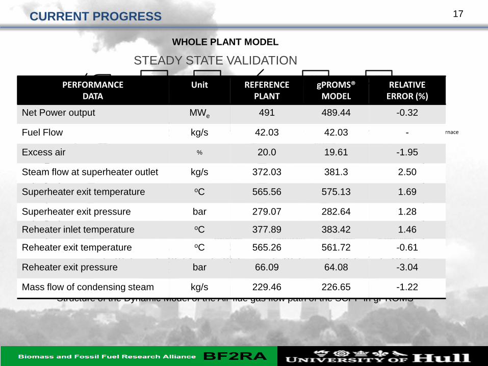
•Steady State Validation
Akeem Olaleye
Process\Energy Systems Engineering Group
Department of Chemical Engineering
School of Engineering
University of Hull
Supervisors:
Dr. Meihong Wang (University of Hull)
Dr. Muhammad Abubakar (BF2RA)
BF2RA-CRF SEMINAR
1
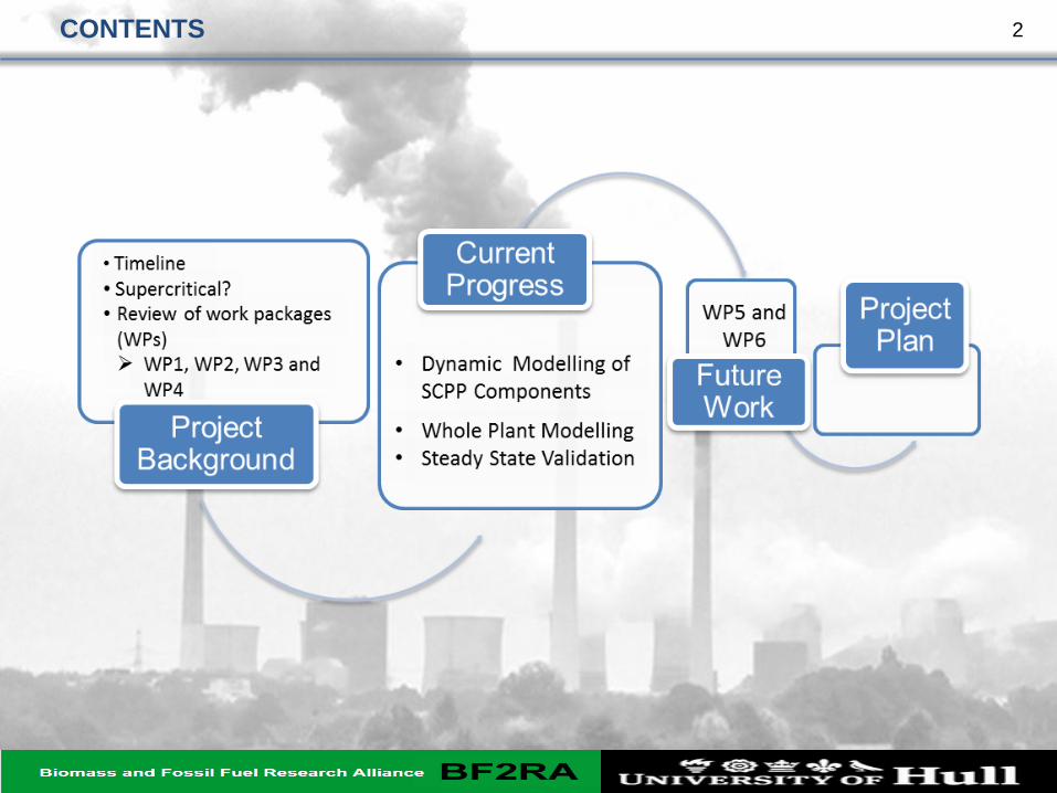
CONTENTS 2
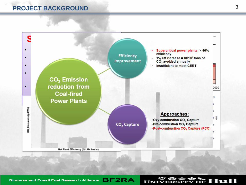
PROJECT BACKGROUND 3
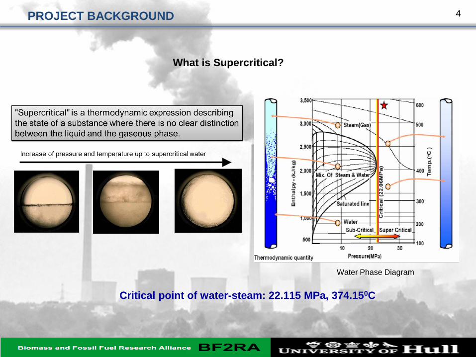
Critical point of water-steam: 22.115 MPa, 374.150C
Water Phase Diagram
PROJECT BACKGROUND
What is Supercritical?
4
PROJECT BACKGROUND
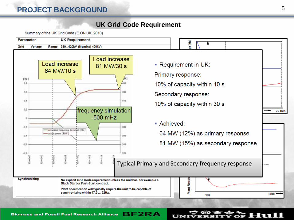
Typical Primary and Secondary frequency response
UK Grid Code Requirement
5
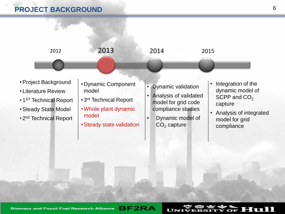
•Project Background
•Literature Review
•1ST Technical Report
•Steady State Model
•2nd Technical Report
•Dynamic Component
model
•3rd Technical Report
•Whole plant dynamic
model
•Steady state validation
2012 2013 2014 2015
• Dynamic validation
• Analysis of validated
model for grid code
compliance studies
• Dynamic model of
CO2 capture
• Integration of the
dynamic model of
SCPP and CO2
capture
• Analysis of integrated
model for grid compliance
PROJECT BACKGROUND 6
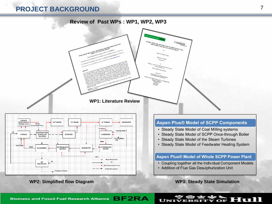
Review of Past WPs : WP1, WP2, WP3
WP1: Literature Review
WP2: Simplified flow Diagram WP3: Steady State Simulation
PROJECT BACKGROUND 7
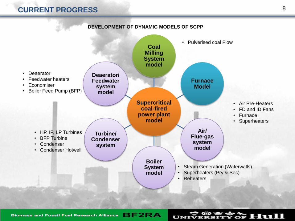
Supercritical coal-fired
power plant model
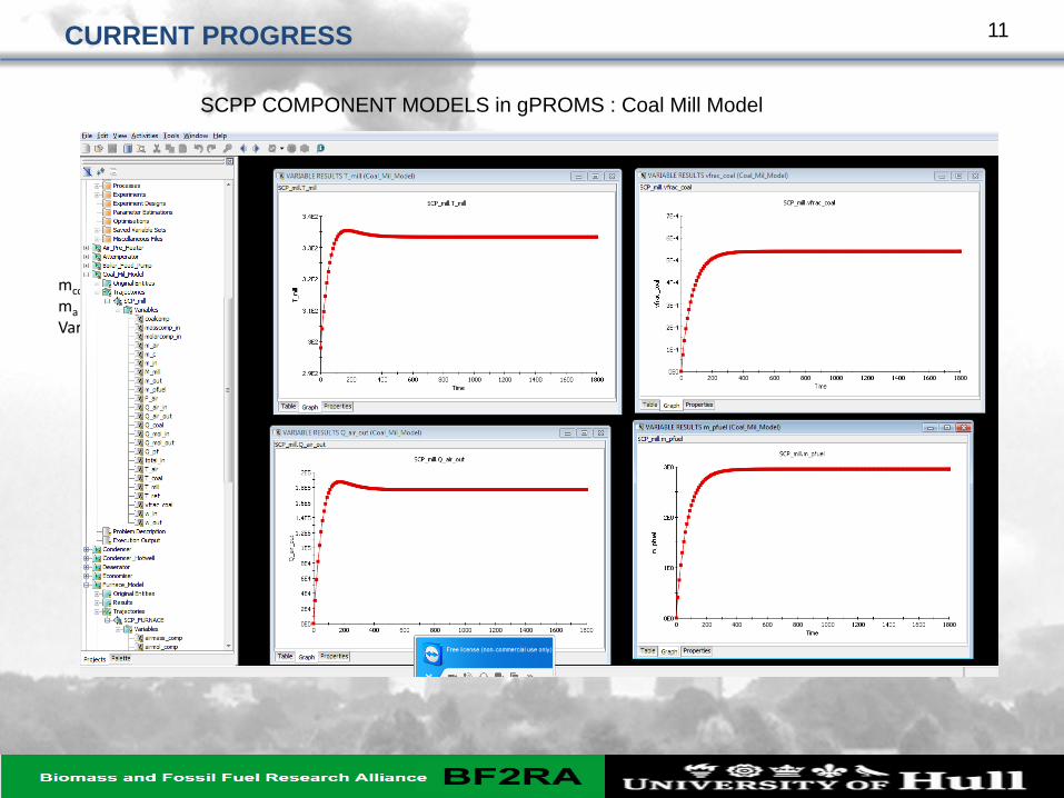
Coal Milling System model
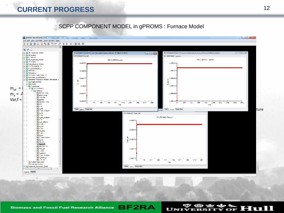
Furnace Model
Air/ Flue-gas system model
Boiler System model
Turbine/ Condenser
system
Deaerator/ Feedwater
system model
• Deaerator
• Feedwater heaters
• Economiser • Boiler Feed Pump (BFP)
• HP, IP, LP Turbines
• BFP Turbine
• Condenser
• Condenser Hotwell
• Steam Generation (Waterwalls)
• Superheaters (Pry & Sec)
• Reheaters
• Pulverised coal Flow
• Air Pre-Heaters
• FD and ID Fans
• Furnace • Superheaters
DEVELOPMENT OF DYNAMIC MODELS OF SCPP
CURRENT PROGRESS 8
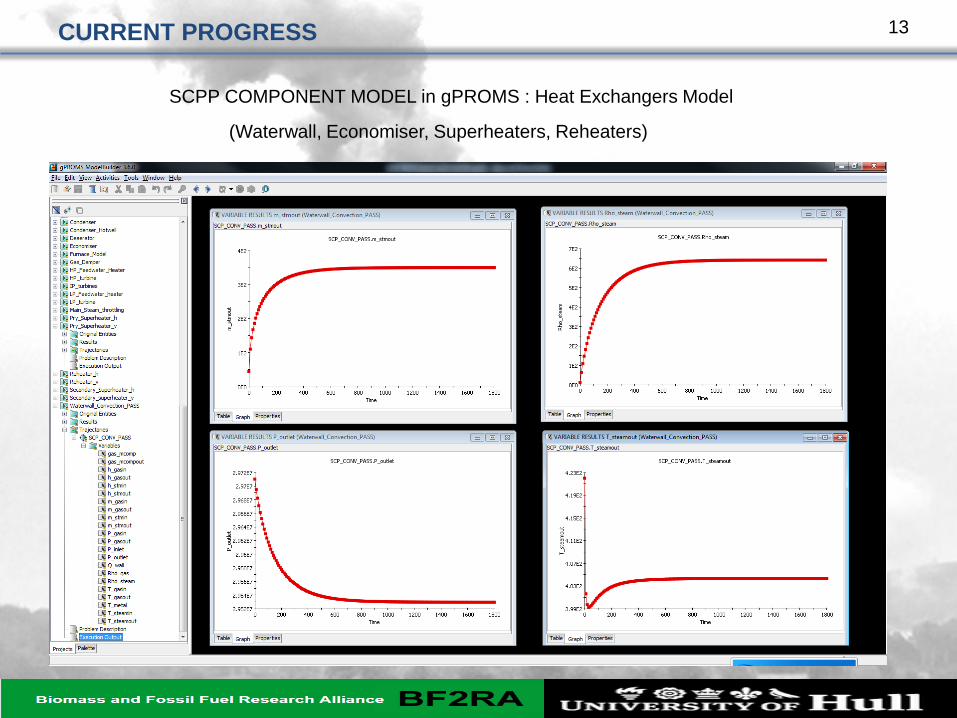
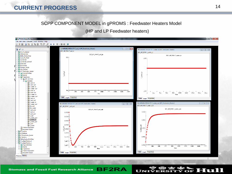
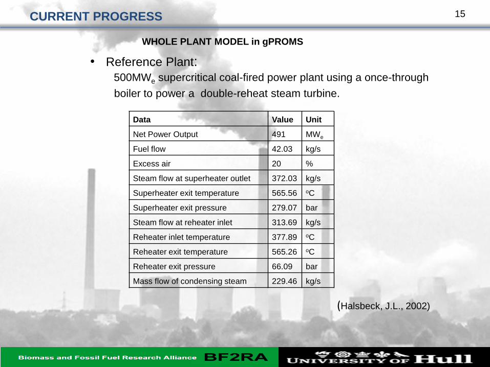
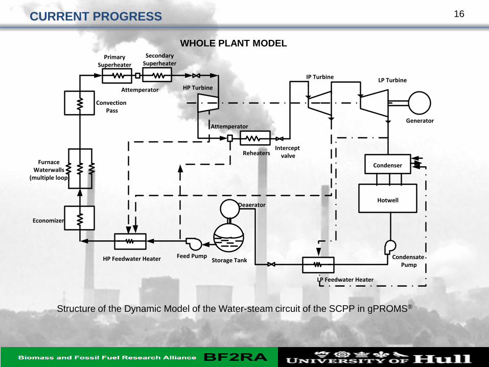
CURRENT PROGRESS
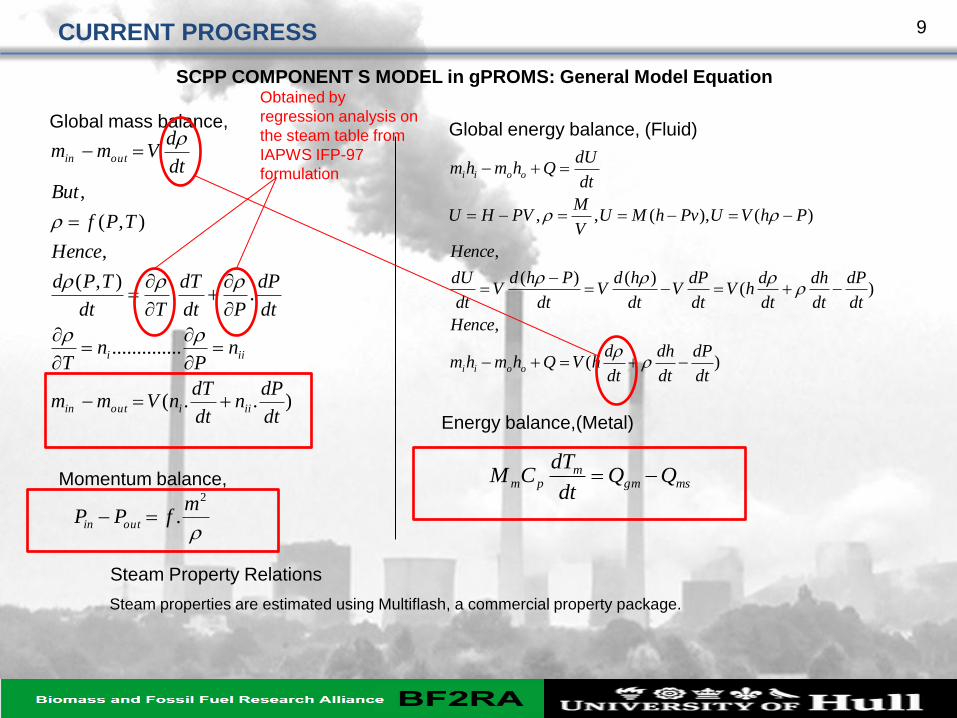
SCPP COMPONENT S MODEL in gPROMS: General Model Equation
Global mass balance,
)..(
..............
..),(
,
),(
,
dt
dPn
dt
dTnVmm
nP
nT
dt
dP
Pdt
dT
Tdt
TPd
Hence
TPf
But
dt
dVmm
iiiout in
iii
out in
)(
,
)()()(
,
)(),(,,
dt
dP
dt
dh
dt
dhVQhmhm
Hence
dt
dP
dt
dh
dt
dhV
dt
dPV
dt
hdV
dt
PhdV
dt
dU
Hence
PhVUPvhMUV
MPVHU
dt
dUQhmhm
ooii
ooii
Global energy balance, (Fluid)
Momentum balance, msgmm
pm QQdt
dTCM
Energy balance,(Metal)
2
.m
fPP outin
Steam Property Relations
Steam properties are estimated using Multiflash, a commercial property package.
Obtained by
regression analysis on
the steam table from
IAPWS IFP-97
formulation
9
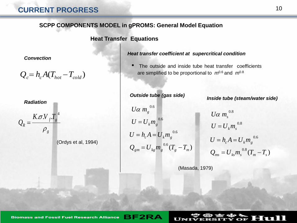
CURRENT PROGRESS
Heat Transfer Equations
Convection
)( coldhotcc TTAhQ
Radiation
g
gf
R
TVKQ
4
...
Heat transfer coefficient at supercritical condition
• The outside and inside tube heat transfer coefficients
are simplified to be proportional to m0.6 and m
0.8
)(6.0
6.0
mggkggm
gkc
TTmUQ
mUAhU
(Ordys et al, 1994)
(Masada, 1979)
SCPP COMPONENTS MODEL in gPROMS: General Model Equation