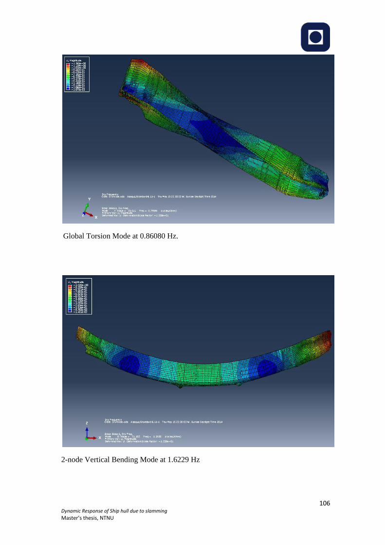
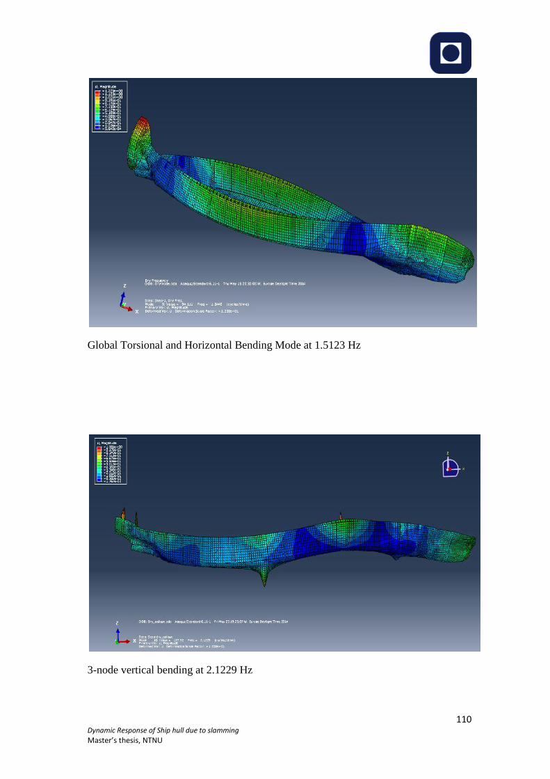
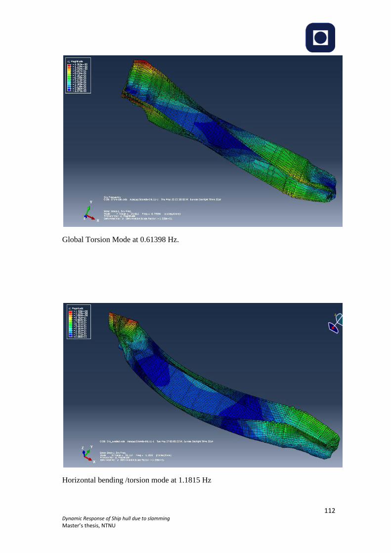
Page 1
Dynamic Response of Ship Hull due to Slamming
Md Emdadul Hoque
Marine Technology
Supervisor: Bernt Johan Leira, IMT
Department of Marine Technology
Submission date: June 2014
Norwegian University of Science and Technology
Page 3
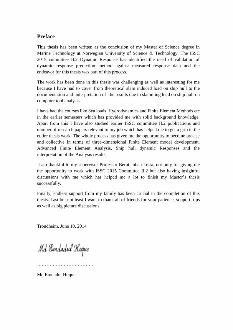
Preface
This thesis has been written as the conclusion of my Master of Science degree in
Marine Technology at Norwegian University of Science & Technology. The ISSC
2015 committee II.2 Dynamic Response has identified the need of validation of
dynamic response prediction method against measured response data and the
endeavor for this thesis was part of this process.
The work has been done in this thesis was challenging as well as interesting for me
because I have had to cover from theoretical slam induced load on ship hull to the
documentation and interpretation of the results due to slamming load on ship hull on
computer tool analysis.
I have had the courses like Sea loads, Hydrodynamics and Finite Element Methods etc
in the earlier semesters which has provided me with solid background knowledge.
Apart from this I have also studied earlier ISSC committee II.2 publications and
number of research papers relevant to my job which has helped me to get a grip in the
entire thesis work. The whole process has given me the opportunity to become precise
and collective in terms of three-dimensional Finite Element model development,
Advanced Finite Element Analysis, Ship hull dynamic Responses and the
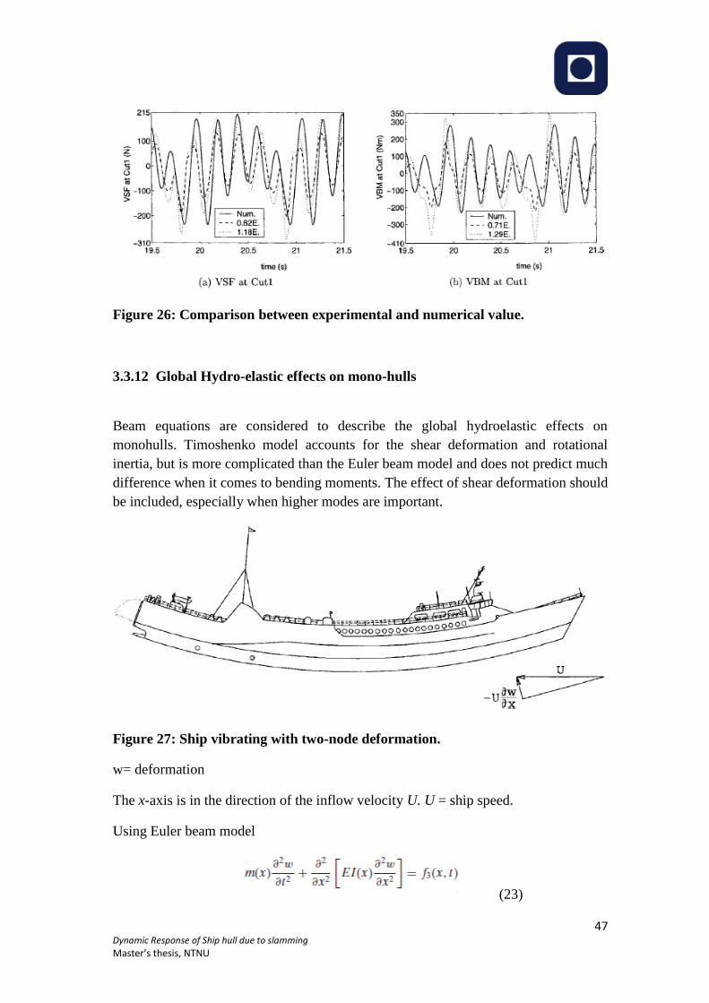
interpretation of the Analysis results.
I am thankful to my supervisor Professor Bernt Johan Leira, not only for giving me
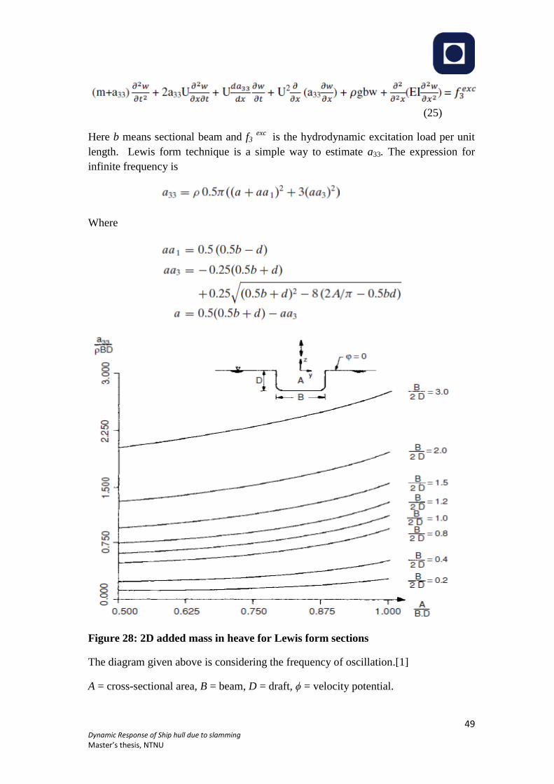
the opportunity to work with ISSC 2015 Committee II.2 but also having insightful
discussions with me which has helped me a lot to finish my Master’s thesis
successfully.
Finally, endless support from my family has been crucial in the completion of this
thesis. Last but not least I want to thank all of friends for your patience, support, tips
as well as big picture discussions.
Trondheim, June 10, 2014
……………………………….
Md Emdadul Hoque
Page 4
2 Dynamic Response of Ship hull due to slamming
Master’s thesis, NTNU
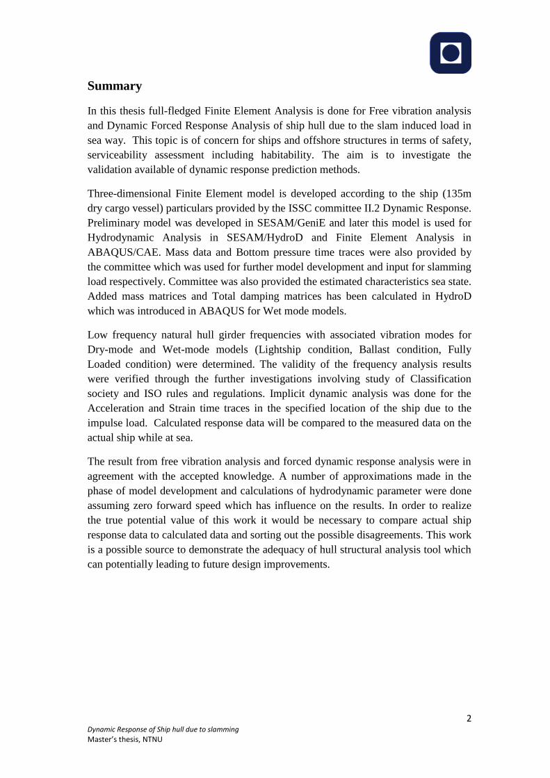
Summary
In this thesis full-fledged Finite Element Analysis is done for Free vibration analysis
and Dynamic Forced Response Analysis of ship hull due to the slam induced load in
sea way. This topic is of concern for ships and offshore structures in terms of safety,
serviceability assessment including habitability. The aim is to investigate the
validation available of dynamic response prediction methods.
Three-dimensional Finite Element model is developed according to the ship (135m
dry cargo vessel) particulars provided by the ISSC committee II.2 Dynamic Response.
Preliminary model was developed in SESAM/GeniE and later this model is used for
Hydrodynamic Analysis in SESAM/HydroD and Finite Element Analysis in
ABAQUS/CAE. Mass data and Bottom pressure time traces were also provided by
the committee which was used for further model development and input for slamming
load respectively. Committee was also provided the estimated characteristics sea state.
Added mass matrices and Total damping matrices has been calculated in HydroD
which was introduced in ABAQUS for Wet mode models.
Low frequency natural hull girder frequencies with associated vibration modes for
Dry-mode and Wet-mode models (Lightship condition, Ballast condition, Fully
Loaded condition) were determined. The validity of the frequency analysis results
were verified through the further investigations involving study of Classification
society and ISO rules and regulations. Implicit dynamic analysis was done for the
Acceleration and Strain time traces in the specified location of the ship due to the
impulse load. Calculated response data will be compared to the measured data on the
actual ship while at sea.
The result from free vibration analysis and forced dynamic response analysis were in
agreement with the accepted knowledge. A number of approximations made in the
phase of model development and calculations of hydrodynamic parameter were done
assuming zero forward speed which has influence on the results. In order to realize
the true potential value of this work it would be necessary to compare actual ship
response data to calculated data and sorting out the possible disagreements. This work
is a possible source to demonstrate the adequacy of hull structural analysis tool which
can potentially leading to future design improvements.
Page 5
3 Dynamic Response of Ship hull due to slamming
Master’s thesis, NTNU
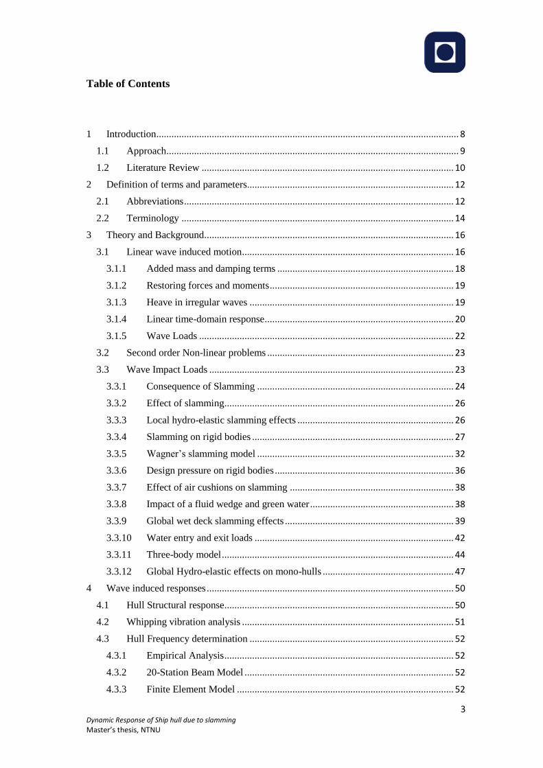
Table of Contents
1 Introduction ........................................................................................................................ 8
1.1 Approach .................................................................................................................... 9
1.2 Literature Review .................................................................................................... 10
2 Definition of terms and parameters.................................................................................. 12
2.1 Abbreviations ........................................................................................................... 12
2.2 Terminology ............................................................................................................ 14
3 Theory and Background ................................................................................................... 16
3.1 Linear wave induced motion .................................................................................... 16
3.1.1 Added mass and damping terms ...................................................................... 18
3.1.2 Restoring forces and moments ......................................................................... 19
3.1.3 Heave in irregular waves ................................................................................. 19
3.1.4 Linear time-domain response ........................................................................... 20
3.1.5 Wave Loads ..................................................................................................... 22
3.2 Second order Non-linear problems .......................................................................... 23
3.3 Wave Impact Loads ................................................................................................. 23
3.3.1 Consequence of Slamming .............................................................................. 24
3.3.2 Effect of slamming ........................................................................................... 26
3.3.3 Local hydro-elastic slamming effects .............................................................. 26
3.3.4 Slamming on rigid bodies ................................................................................ 27
3.3.5 Wagner’s slamming model .............................................................................. 32
3.3.6 Design pressure on rigid bodies ....................................................................... 36
3.3.7 Effect of air cushions on slamming ................................................................. 38
3.3.8 Impact of a fluid wedge and green water ......................................................... 38
3.3.9 Global wet deck slamming effects ................................................................... 39
3.3.10 Water entry and exit loads ............................................................................... 42
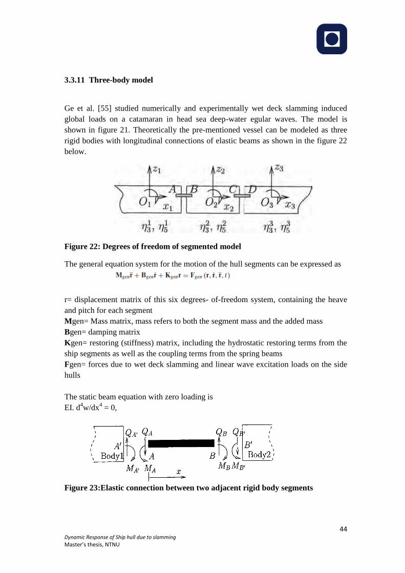
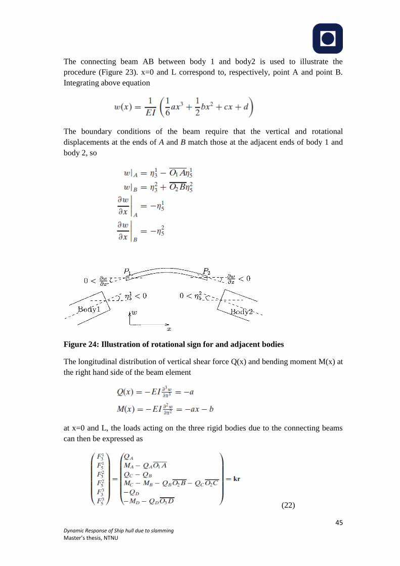
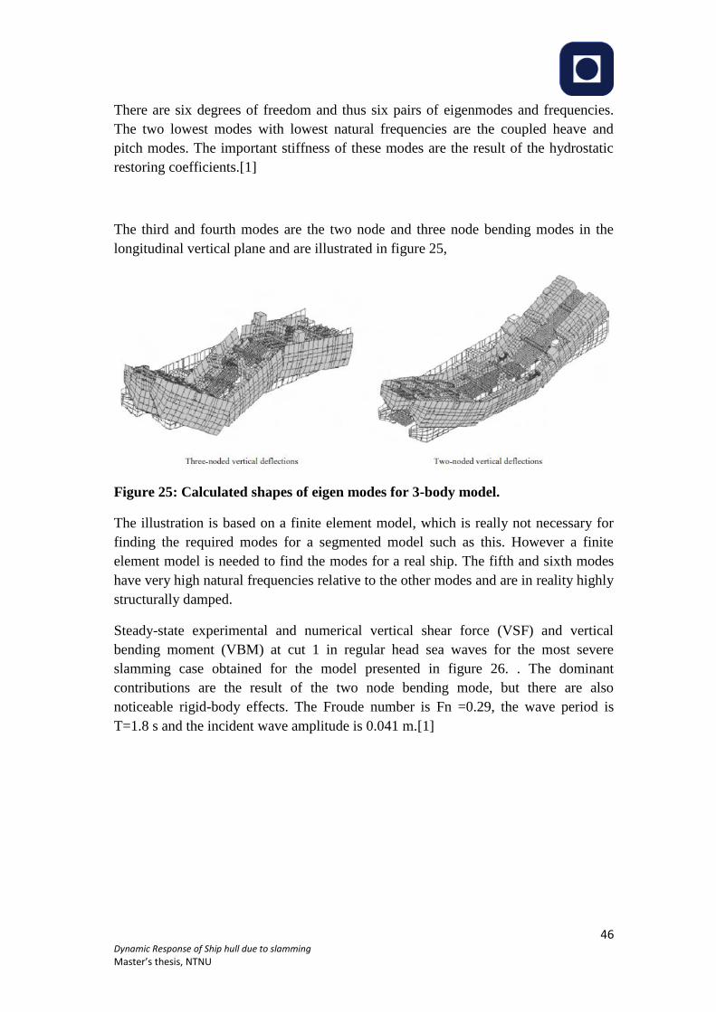
3.3.11 Three-body model ............................................................................................ 44
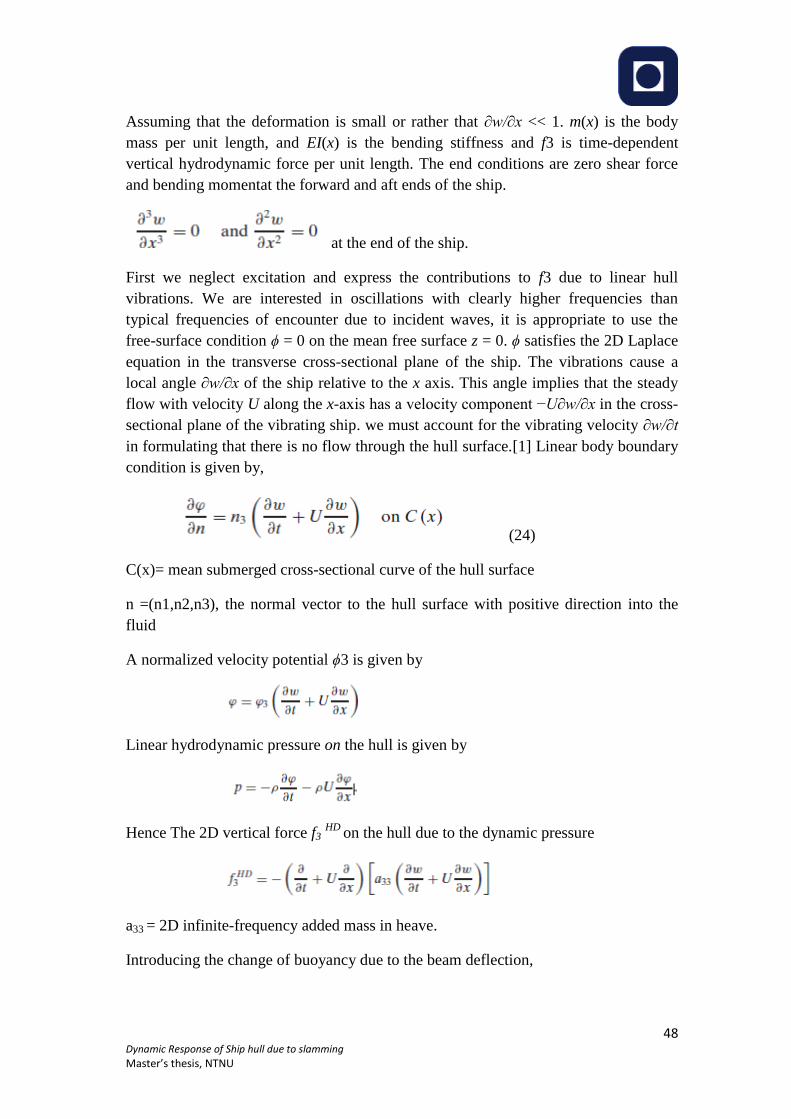
3.3.12 Global Hydro-elastic effects on mono-hulls .................................................... 47
4 Wave induced responses .................................................................................................. 50
4.1 Hull Structural response ........................................................................................... 50
4.2 Whipping vibration analysis .................................................................................... 51
4.3 Hull Frequency determination ................................................................................. 52
4.3.1 Empirical Analysis ........................................................................................... 52
4.3.2 20-Station Beam Model ................................................................................... 52
4.3.3 Finite Element Model ...................................................................................... 52
Page 6
4 Dynamic Response of Ship hull due to slamming
Master’s thesis, NTNU
4.4 Dynamic Analysis .................................................................................................... 53
4.4.1 Overview .......................................................................................................... 53
4.4.2 Implicit Versus Explicit ................................................................................... 54
4.4.3 Time integration methods ................................................................................ 55
4.4.4 Damping in dynamic analysis .......................................................................... 56
4.4.5 Frequency Extraction procedure ...................................................................... 57
4.4.6 Eigen Extraction methods ................................................................................ 57
5 Input Data ........................................................................................................................ 58
5.1 Ship data .................................................................................................................. 58
5.2 FE Model ................................................................................................................. 59
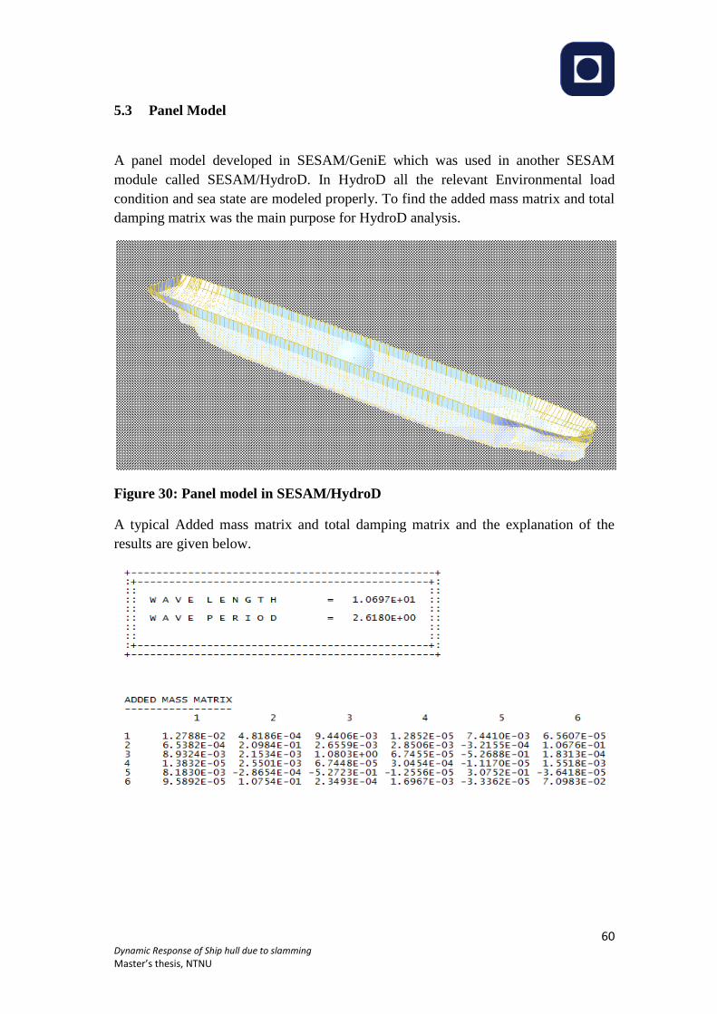
5.3 Panel Model ............................................................................................................. 60
5.4 ABAQUS model ...................................................................................................... 61
6 Analysis and Results ........................................................................................................ 66
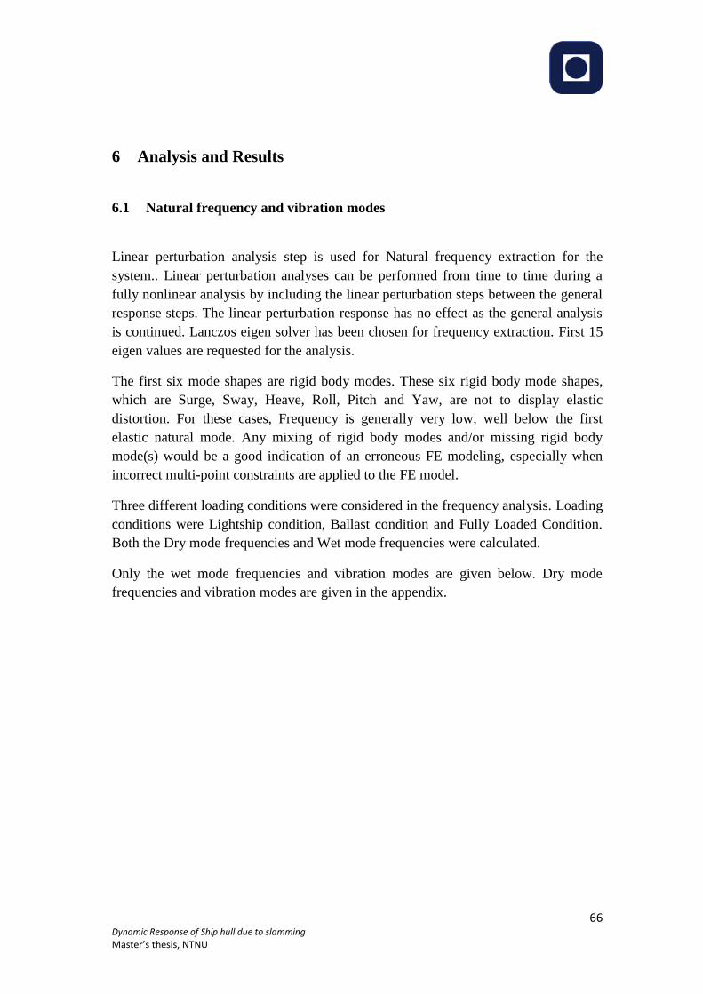
6.1 Natural frequency and vibration modes ................................................................... 66
6.1.1 Wet mode frequencies and mode shapes ......................................................... 67
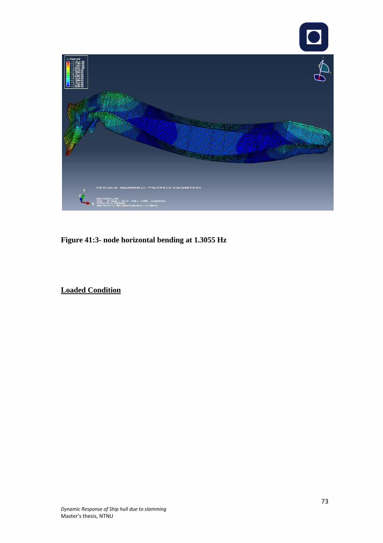
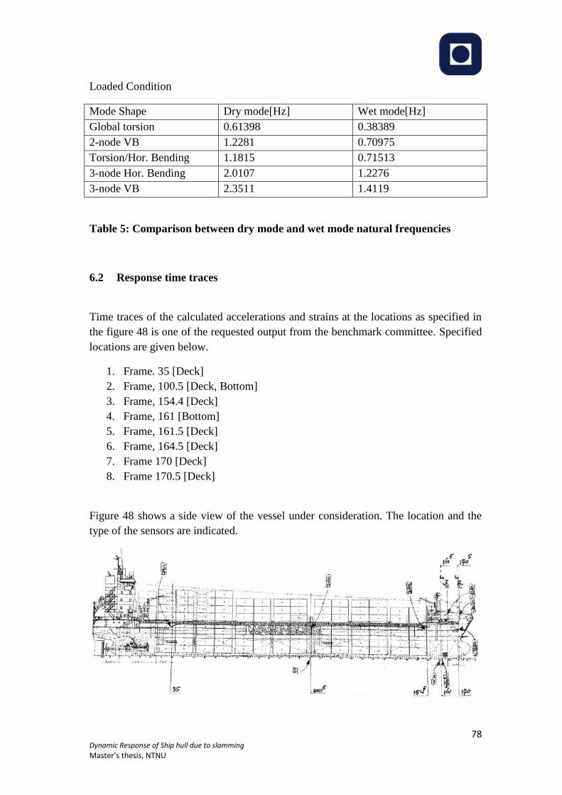
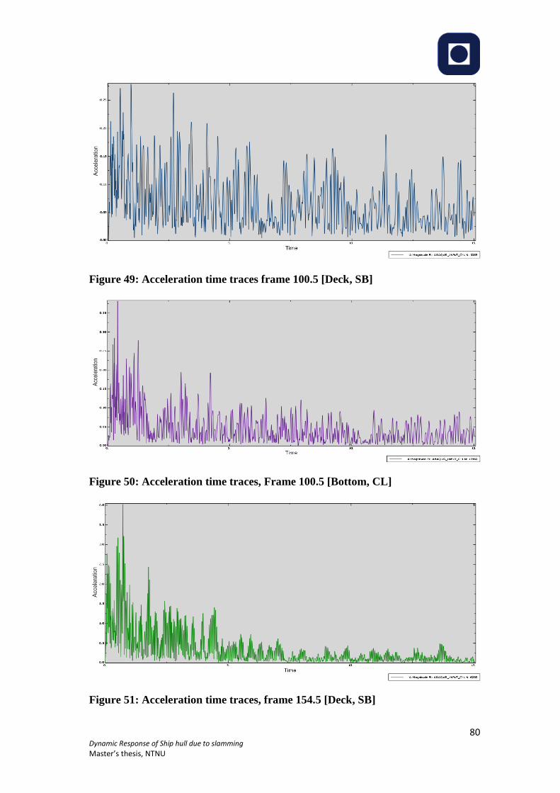
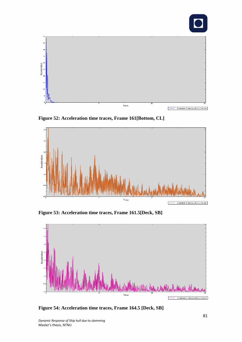
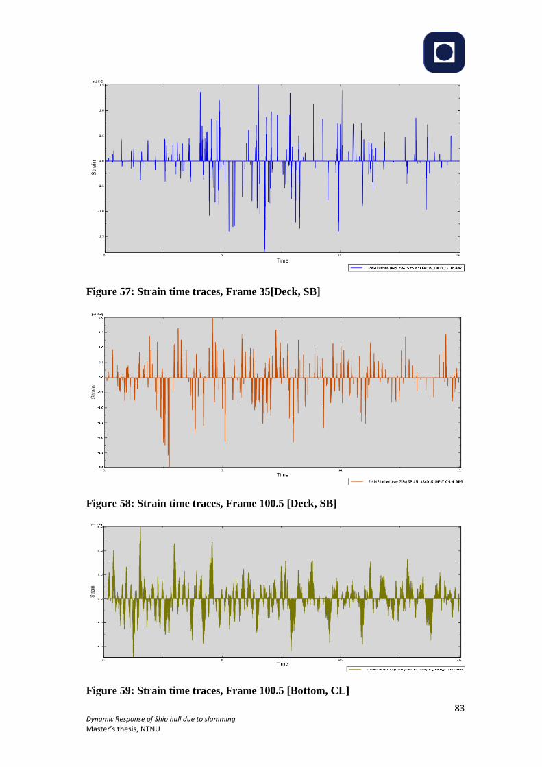
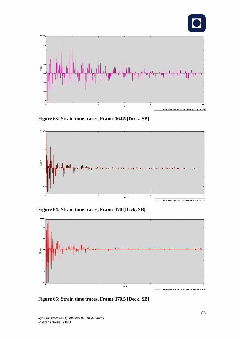
6.2 Response time traces ................................................................................................ 78
6.2.1 Acceleration time traces ................................................................................... 79
6.2.2 Strain time traces ............................................................................................. 82
7 Discussion and Conclusions ............................................................................................ 87
8 Recommendation for future work .................................................................................... 90
9 References ........................................................................................................................ 91
Appendices .............................................................................................................................. 95
9.1 Appendix A .............................................................................................................. 95
9.2 Appendix B ............................................................................................................ 100
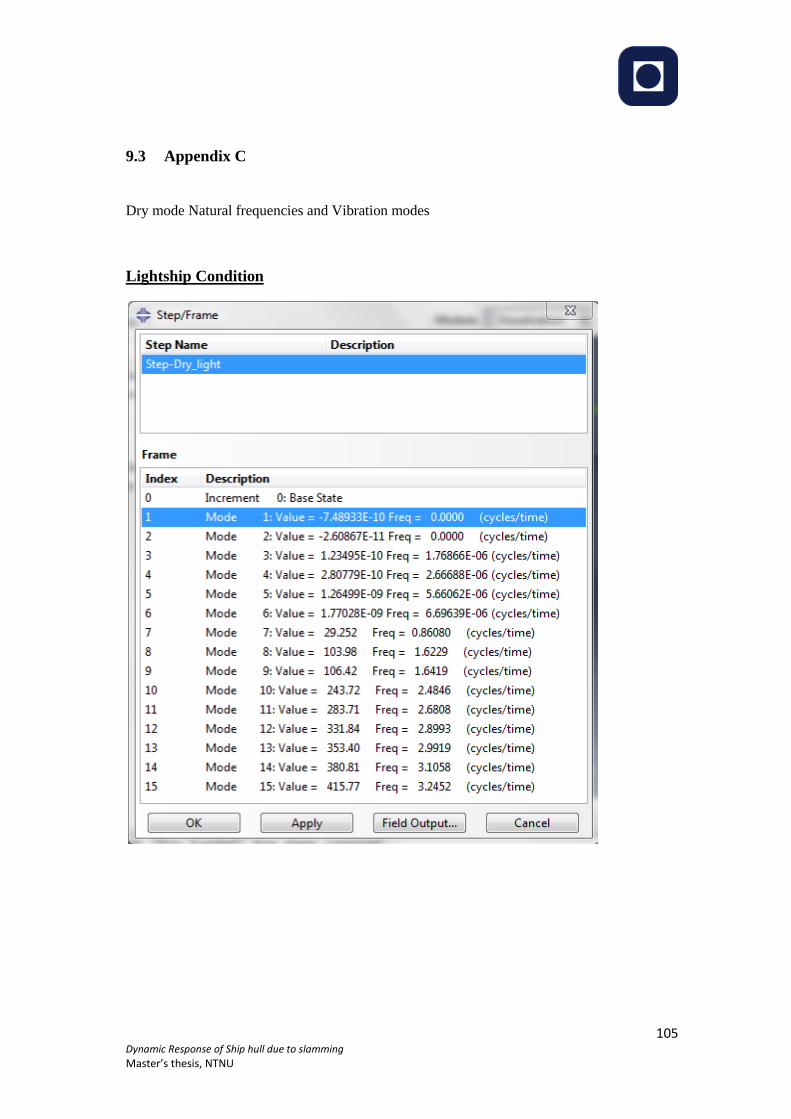
9.3 Appendix C ............................................................................................................ 105
Page 7
5 Dynamic Response of Ship hull due to slamming
Master’s thesis, NTNU
List of Figures
Figure 1: Co-ordinate system ................................................................................................... 16 Figure 2: Super position wave excitation, added mass, damping and restoring loads ............. 18 Figure 3: Heave response in irregular long-crested head waves .............................................. 20 Figure 4: Global forces and moments on hull girder [1] ......................................................... 22 Figure 5: Wet deck slamming [1] ............................................................................................ 25 Figure 6: Prediction of pressure distribution during water entry of a rigid wedge .................. 29 Figure 7: Slamming pressure parameters during water entry of a blunt 2D rigid body. .......... 29 Figure 8: The vertical slamming force on symmetric wedge................................................... 30 Figure 9: Vertical slamming force on a wedge with knuckles. Dead rise angle is 20 deg. ..... 31 Figure 10: Water entry of a wedge with constant velocity V. Definition of inner and jet flow
domains. ................................................................................................................................... 32 Figure 11: Definition of parameters in analysis of impact forces (Wagner model) ................. 32 Figure 12: Boundary-value problem for the velocity potential in simplified analysis. ........... 33 Figure 13: Definition of polar co-ordinates (r1, 1) and (r2, 2) used in evaluating the complex
function. ................................................................................................................................... 34 Figure 14: Water entry of a wedge shaped elastic cross section .............................................. 36 Figure 15: Stiffened panel consisting of plate and longitudinal stiffener. ............................... 37 Figure 16: Deformation of the free surface and formation of an air pocket during entry of a
rigid body ................................................................................................................................. 38 Figure 17: Impact of fluid wedge and green water .................................................................. 39 Figure 18: Measured vertical acceleration at the forward perpendicular (FP) of the ulstein test
catamaran. ................................................................................................................................ 40 Figure 19: Position of slamming on the wet deck in regular head sea waves as a function of
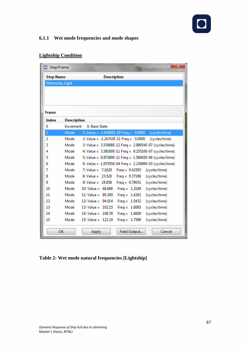
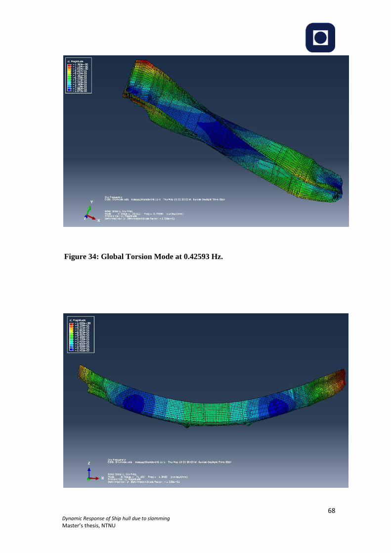
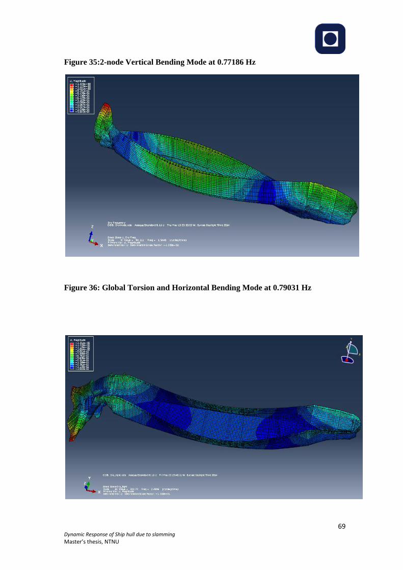
wave lenght. ............................................................................................................................. 41 Figure 20:2D boundary value problem for velocity potential due to wet deck slamming ....... 42 Figure 21: Outline of the experimental hull arrangements (top view) ( Ge 2002) .................. 43 Figure 22: Degrees of freedom of segmented model ............................................................... 44 Figure 23:Elastic connection between two adjacent rigid body segments ............................... 44 Figure 24: Illustration of rotational sign for and adjacent bodies ............................................ 45 Figure 25: Calculated shapes of eigen modes for 3-body model. ............................................ 46 Figure 26: Comparison between experimental and numerical value. ...................................... 47 Figure 27: Ship vibrating with two-node deformation. ........................................................... 47 Figure 28: 2D added mass in heave for Lewis form sections .................................................. 49 Figure 29: Ship preliminary model in GeniE. .......................................................................... 59 Figure 30: Panel model in SESAM/HydroD ........................................................................... 60 Figure 31: Element properties .................................................................................................. 63 Figure 32: Mesh model in ABAQUS ...................................................................................... 64 Figure 33: Frequency Analysis Steo in ABAQUS .................................................................. 65 Figure 34: Global Torsion Mode at 0.42593 Hz. ..................................................................... 68 Figure 35:2-node Vertical Bending Mode at 0.77186 Hz ........................................................ 69 Figure 36: Global Torsion and Horizontal Bending Mode at 0.79031 Hz .............................. 69 Figure 37: 3- node horizontal bending at 1.3188 Hz ............................................................... 70 Figure 38: Global Torsion Mode at 0.41509 Hz. ..................................................................... 71 Figure 39:2-node Vertical Bending Mode at 0.73877 Hz ........................................................ 72 Figure 40: Global Torsion and Horizontal Bending Mode at 0.77515 Hz .............................. 72 Figure 41:3- node horizontal bending at 1.3055 Hz ................................................................ 73 Figure 42: Global Torsion Mode at 0.38389 Hz ...................................................................... 75 Figure 43:2-node Vertical Bending Mode at 0.70975 Hz ........................................................ 75 Figure 44: Horizontal bending /torsion mode at 0.71513 Hz .................................................. 76
Page 8
6 Dynamic Response of Ship hull due to slamming
Master’s thesis, NTNU
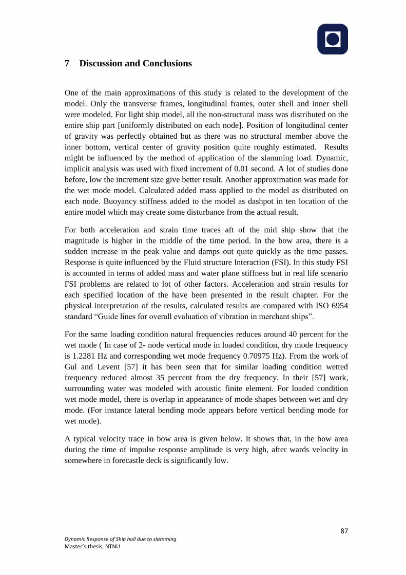
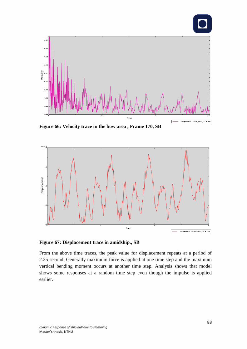
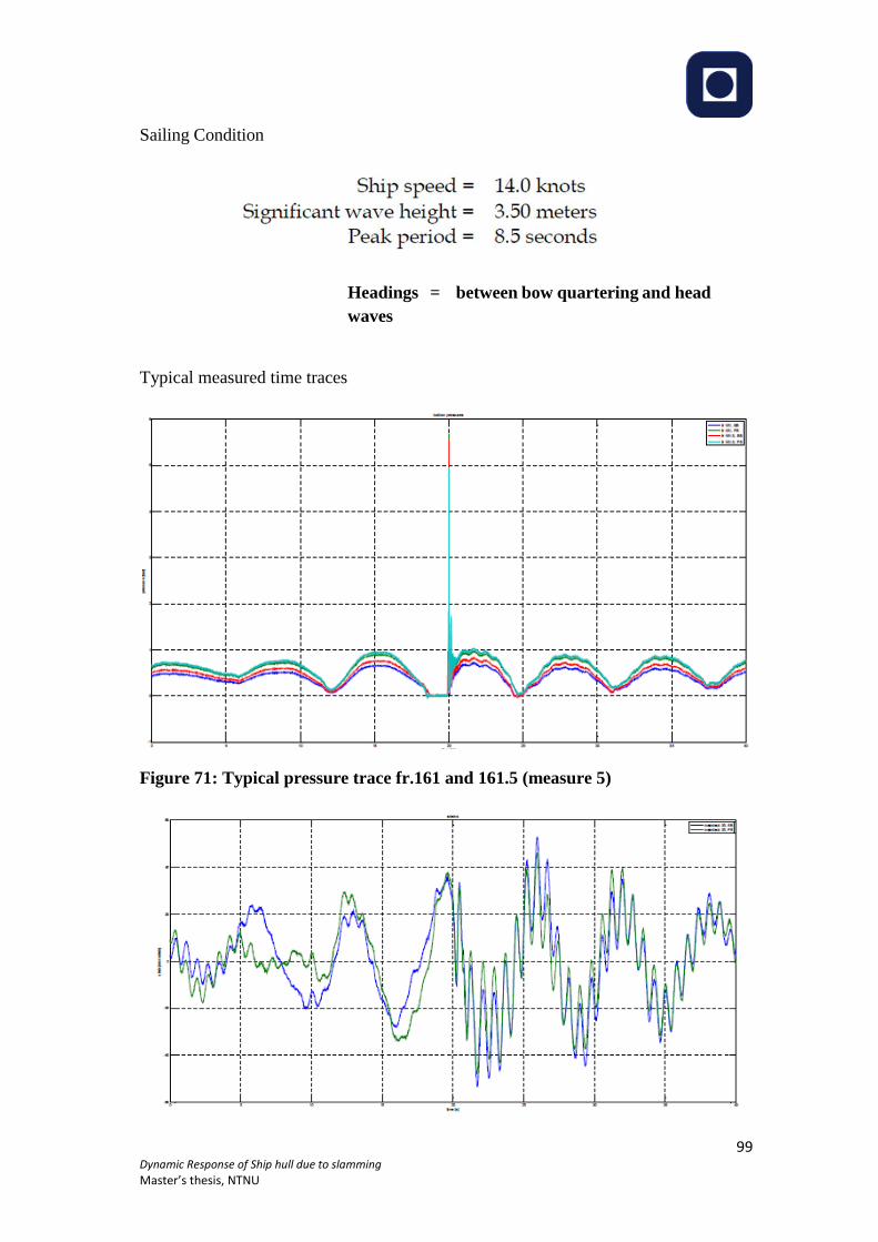
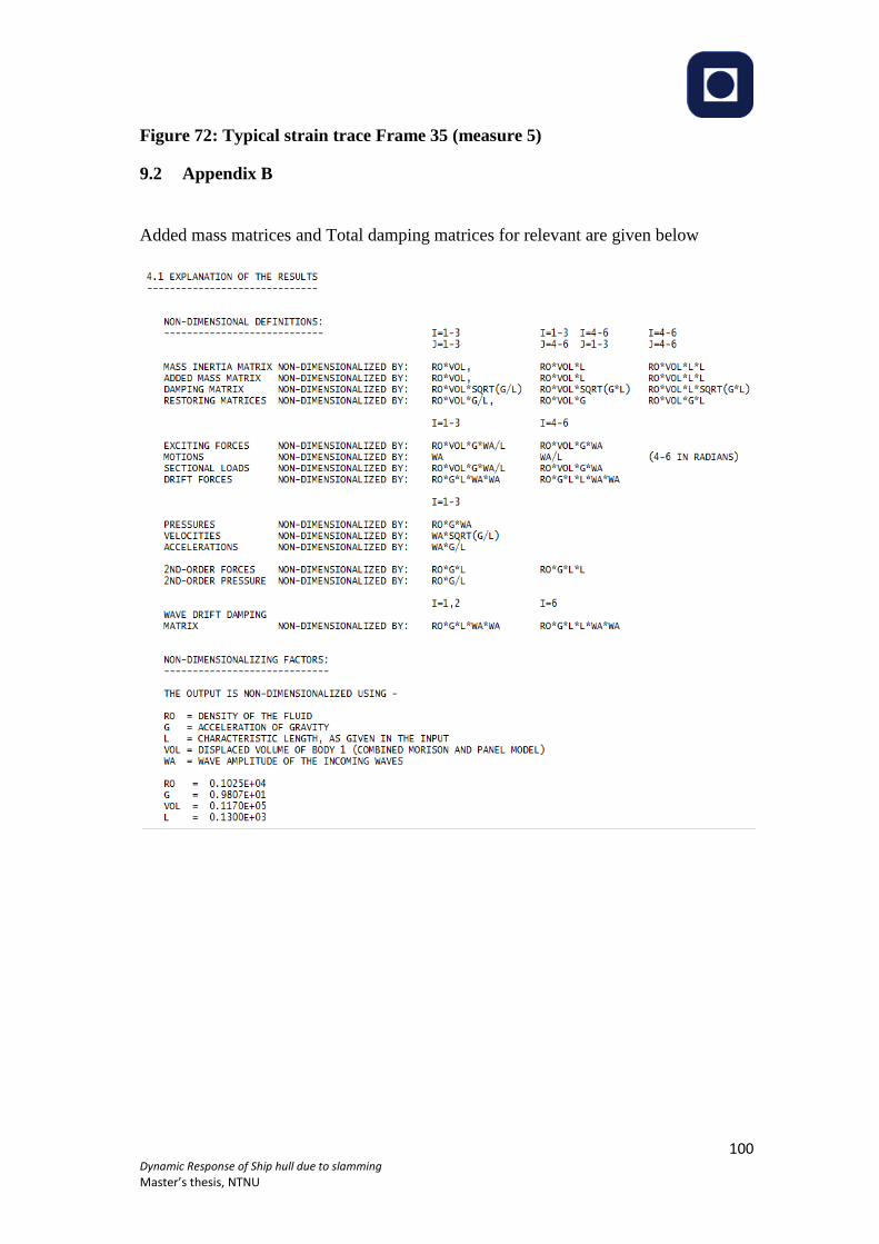
Figure 45:3- node horizontal bending at 1.2276 Hz ................................................................ 76 Figure 46:3- node vertical bending at 1.4119 Hz .................................................................... 77 Figure 47: 135 m dry cargo vessel, sensor locations indicated. ............................................... 79 Figure 48: Acceleration time traces Frame 35 [Deck, SB] ...................................................... 79 Figure 49: Acceleration time traces frame 100.5 [Deck, SB] .................................................. 80 Figure 50: Acceleration time traces, Frame 100.5 [Bottom, CL] ............................................ 80 Figure 51: Acceleration time traces, frame 154.5 [Deck, SB] ................................................. 80 Figure 52: Acceleration time traces, Frame 161[Bottom, CL] ................................................ 81 Figure 53: Acceleration time traces, Frame 161.5[Deck, SB] ................................................. 81 Figure 54: Acceleration time traces, Frame 164.5 [Deck, SB] ................................................ 81 Figure 55: Acceleration time traces, Frame 170 [Deck, SB] ................................................... 82 Figure 56: Acceleration time traces, frame 170.5 [Deck, SB] ................................................. 82 Figure 57: Strain time traces, Frame 35[Deck, SB] ................................................................. 83 Figure 58: Strain time traces, Frame 100.5 [Deck, SB] ........................................................... 83 Figure 59: Strain time traces, Frame 100.5 [Bottom, CL] ....................................................... 83 Figure 60: Strain time traces, Frame 154.5 [Deck, SB] ........................................................... 84 Figure 61: Strain time traces, Frame 161 [Bottom, CL] ......................................................... 84 Figure 62: Strain time traces, frame 161.5 [Deck, SB] ............................................................ 84 Figure 63: Strain time traces, Frame 164.5 [Deck, SB] ........................................................... 85 Figure 64: Strain time traces, Frame 170 [Deck, SB] .............................................................. 85 Figure 65: Strain time traces, Frame 170.5 [Deck, SB] ........................................................... 85 Figure 66: Velocity trace in the bow area , Frame 170, SB ..................................................... 88 Figure 67: Displacement trace in amidship., SB ...................................................................... 88 Figure 68: Stress [mises] plot in bow and stern area, SB ........................................................ 89 Figure 69: General Arrangement ............................................................................................. 97 Figure 70: Lines Plan ............................................................................................................... 98 Figure 71: Typical pressure trace fr.161 and 161.5 (measure 5) ............................................. 99 Figure 72: Typical strain trace Frame 35 (measure 5) ........................................................... 100
Page 9
7 Dynamic Response of Ship hull due to slamming
Master’s thesis, NTNU
List of Tables
Table 1: Hilber- Hughes- Taylor integrator parameters[41] .................................................... 55 Table 2: Wet mode natural frequencies [Lightship] ................................................................ 67 Table 3: Wet mode natural frequencies [Ballast condition] .................................................... 70 Table 4: Wet mode natural frequencies [Loaded] .................................................................... 74 Table 5: Comparison between dry mode and wet mode natural frequencies .......................... 78 Table 6: Mass data ................................................................................................................... 96
Page 10
8 Dynamic Response of Ship hull due to slamming
Master’s thesis, NTNU
1 Introduction
Technology is changing day by day. From concept design to the service condition of a
ship or an offshore floating structure involved with lot of procedure, estimation and
calculation. Well established rules and guidelines for all the aspects (designing,
construction, operation) during the Ship shelf life are available of. The main area of
this thesis work is about the dynamic response of ship. Dynamic Structural response
of ships and floating offshore structures is a concern in terms of safety and
serviceability assessment, including habitability. There are different procedure and
technique are available to predict the dynamic response of ship. To estimate the
response to the highest level of accuracy validation of existing prediction methods is
important and it is a continuous process.
The purpose of the work is to investigate the adequacy of various hull structural
analysis tools for predicting ship hull dynamic response due to slamming.
In 2002 TNO participated in a joint industry project (JIP), concerning a long term
measuring campaign on an ocean going general cargo ship. The owner Wangenborg
has kindly granted ISSC community access to the ship particulars, while all JIP
partners agreed to share some of measured time traces.
Fluid-structure interaction (FSI) problems have been studied in many diverse research
areas for several decades. There are many FSI problems that are relevant in the
maritime research area such as sloshing in a tanker ship, propulsion system, green
water and wave-induced loads on a ship or offshore structure. Ship hull is vulnerable
to unsteady wave, wind, and current loading. Among those external loads mentioned
earlier wave induced forces present the most considerable design problem for ship
owners, shipbuilders and classification societies. Dynamic wave- induced loads are
mostly two types: Global loads and Local Loads. Global loads are induced by the
unsteady hydrodynamic pressure because of the fluid oscillatory motions surrounding
the hull while the local or secondary loads, such as slamming and whipping are due to
wave impacts.
Study of transient dynamic response of ship structure due slamming pressure
impulsive load is the main focus of this thesis work. ISSC 2015, Committee II.2,
benchmark provided all the information related to vessel and corresponding sea state.
Slamming response time traces is predicted at location of sensors [Strain,
acceleration, pressure] along the hull girder. At the final stage, comparison will be
made with actual measured data from a trip in the Laurentian trough off the coast of
Nova Scotia, Canada.
Page 11
9 Dynamic Response of Ship hull due to slamming
Master’s thesis, NTNU
1.1 Approach
The work has been progressed in several stages. At the first stage, External loads
which acts on the ship hull girder due to waves and transient loads for example due
slamming have been studied. A detail study has performed about slam induced loads
on the ship hull. Experimental results from other work, theoretical background,
corresponding load models, load calculation procedure and computer tools for
dynamic analysis, vibration and frequency analysis are also studied. In the second
stage finite element theory has been emphasized. Natural frequency extraction
procedure and implicit dynamic analysis procedure has considered for computer tool
ABAQUS/CAE. In the next stage, Hull girder model is established in SESAM/GeniE
from the ship particulars given by the committee. Two different models were exported
from GeniE: one was panel model for Hydrodynamic analysis in SESAM/HydroD
and other one was for ABAQUS/CAE that was imported later on as part model. The
part model is further developed in ABAQUS for respective purposes. Hydrodynamic
properties are calculated in HydroD Considering the specified characteristic sea state
in which the ship sails, in terms of significant wave height Hs, wave zero crossing
period Tp, main heading and sailing speed. The dry and wet natural modes and
frequencies have been analyzed for the 2 and 3- node mode shapes in ABAQUS. At
the last stage, for given time histories of the load impulses that act on the fore part of
the hull, dynamic response analysis has been performed. The corresponding time
series of acceleration, strain has been established for different Loading conditions.
Page 12
10 Dynamic Response of Ship hull due to slamming
Master’s thesis, NTNU
1.2 Literature Review
Full scale measurements and model test have been done in the previous years. Most of
the measurements and tests were focused on larger ships i.e. Container ships, bulk
carriers, frigates and LNG carriers. Researches were focused on the effect of wave-
induced vibration on fatigue performance as well as wet deck slamming for high
speed catamarans.
Gaidai Et al.[5] Proposed a formulation for prediction of the extreme stresses
measured in the deck amidships of a container vessel during operation in harsh
weather using the full scale measurement data. The method opens a new window to
predict simply and efficiently both short-term and long-term extreme response
statistics.
Lee et al. [6] reported time domain whipping and springing analyses for a 10000 TEU
class container ship using computational tools as a part of a joint industry project
(JIP). The results from the computational analyses in regular waves have been
correlated with those from model tests undertaken by MOERI. It was reported that the
wave induced vertical bending moments with whipping vibration were reasonably
well predicted by 3D no-linear hydro elasticity method.
Ochi and Motter [7] offered a complete description of the slamming problem.
Account of a large number of unknowns required for the determination of the
whipping stresses they have suggested some simple formulae for the calculation of the
wave-induced slamming loads, for practical purposes. All these formulae were based
on experiments with frigate models. They stressed the importance at the design stage
of the combined effect of wave-induced and whipping stresses, i.e. the total bending
moment induced by the waves.
The work of Kawakami et al, [8] was based on experimental work for a tanker,
proposed an expression for the time history of the slamming loads. They found that
the Ochi and Motter [7] work slightly under predicts the maximum slamming pressure
when compared with the experimental measurements.
Belik et al. [9] understood that the bottom slamming could be divided into two
separate components: impact and momentum slamming. Based on this assumption
they used the Ochi and Motter [7] method for the determination of the maximum
slamming pressure and the Kawakami et al. expression for the determination of the
time history of the slamming impact force. After that, they carried out calculations for
the vertical bending moments and shear forces in regular head seas.
Belik and Price [10] used the same formulation to made comparisons for two different
slamming theories using time simulation of ship responses in irregular seas. They
Page 13
11 Dynamic Response of Ship hull due to slamming
Master’s thesis, NTNU
found that slamming response magnitude depend on the numerical model adopted in
the calculation of the slamming loads.
The non-linear ship motions were calculated by Yamamoto et al. [11] based on the
equations given by the linear theory but with time-varying coefficients dependent on
the instantaneous sectional draft. They included the hydrodynamic impact component
given by the rate of change of the sectional added mass, considering that this force
only acts on the vessel when the section is penetrating the water. Afterwards they did
some experiments and calculations on a bulk carrier model for head seas. They found
that the accuracy of the calculation of the hydrodynamic coefficients has a Significant
influence on the results of the slamming forces, and the computation with accurate
coefficients results in better agreement with experiments.
Tao and Incecik [16] found the large-amplitude motions and bow flare slamming
pressures in regular waves. The non-linear restoring, damping and fluid momentum
forces were considered in predicting ship motions in the time domain. The momentum
slamming theory and Wagner theory were used to predict the bow flare slamming
pressures. The bow flare slamming pressures were calculated by separating the
pressure into the water immersion impact pressure and the wave striking impact
pressure. A satisfactory correlation between the results of predictions and model test
measurements was obtained.
Sames et al. [17] applied a finite-volume method to predict impact coefficients around
the bow region of a ship during slamming. Ship motions in regular waves were
predicted by a linear panel method which takes into account incident, diffracted and
radiated waves. The impact pressures were calculated by processing the results of the
computed pressure coefficients and the transfer functions of ship motions in the time
domain. No comparisons with the measurements were given.
Comparisons between the full-scale measurements and theoretical predictions were
carried out by Aksu et al. [18] for a fast patrol boat travelling in rough seas. Due to
the uncertainty of the wave measurements in a real sea state, the experimental results
of the vertical bending moments were compared with calculations for two different
sea states in a histogram form and satisfactory results were found.
It was found by Ramos and Guedes Soares [13] that the several slamming load
formulations can produce large differences in the slamming pressures, loads and also
in primary stresses. The Ochi and Motter method under predicts the pressures, loads
and also bending moments when compared with the other methods.
[19]
Page 14
12 Dynamic Response of Ship hull due to slamming
Master’s thesis, NTNU
2 Definition of terms and parameters
This section contains the definition of the technical words and abbreviations have
been used in the report.
2.1 Abbreviations
Ƞ1, translatory displacement in X-direction with respect to origin, surge
Ƞ 2, translatory displacement inY-direction with respect to origin, sway
Ƞ 3, translatory displacement in Z-direction with respect to origin, heave
Ƞ 4, angular displacement of the rotational motion about the X-axis, roll
Ƞ 5, angular displacement of the rotational motion about the Y-axis, pitch
Ƞ 6, angular displacement of the rotational motion about the Z-axis, yaw
Fk, Force component
Akj, added mass co-efficient
Bkj, damping co-efficient
Ckj, Restoring co-efficient
ρ, Density of water
g, acceleration due to gravity
Awp, water plane area
B, maximum wedge breadth
ϕ, velocity potential
λ, wavelength
Fn, Froude number
A, submerged cross sectional area
d, sectional draft
a33, 2D infinite frequency added mass in heave
b, sectional beam
f33exe
, hydrodynamic excitation load per unit length
U, ship speed
CB, block co-efficient
f33HD
, 2D vertical force on the hull due to dynamic pressure
ϕ3, velocity potential due to forced heave with unit velocity
C(x), mean submerged cross-sectional curve of the hull surface
n = (n1, n2, n3), the normal vector to the hull surface with positive direction into the
fluid
T, wave period
QA, shear force at point A
MA, bending moment at point A
Mgen, mass matrix
Page 15
13 Dynamic Response of Ship hull due to slamming
Master’s thesis, NTNU
Bgen, Damping matrix
Kgen, restoring matrix
r, displacement matrix
Fgen, the forces due to wet deck slamming and linear wave excitation loads
w, elastic deflection of beam
EI, bending stiffness
h(x), is the time-independent wetdeck height above calm water
ȠB (x,t), vertical ship motion
S, motion at any point on the body
V, displaced volume of water
zb, z co-ordinate of the centre of buoyancy
β, dead rise angle
Pa, atmospheric pressure
Cp, pressure co-efficient
t, time variable
F3, the vertical slamming force
Page 16
14 Dynamic Response of Ship hull due to slamming
Master’s thesis, NTNU
2.2 Terminology
Ahead: Forward of the bow
Amidships (or midships): In the middle portion of ship, along the line of the keel.
Beam Sea: A sea where waves are moving perpendicular to the direction a ship is
moving.
Bow: The front of a vessel.
Bulbous bow: A protruding bulb at the bow of a ship just below the waterline which
modifies the way water flows around the hull, reducing drag and thus increasing
speed, range, fuel efficiency, and stability.
Cargo Ship: Any sort of ship or vessel that carries cargo, goods, and materials from
one port to another, including general cargo ships (designed to carry break bulk
cargo), bulk carriers, container ships, multipurpose vessels, and tankers. Tankers,
however, although technically cargo ships, are routinely thought of as constituting a
completely separate category
Course: The direction in which a vessel is being steered, usually given in degrees.
Dead rise: The design angle between the keel (q.v.) and horizontal.
Displacement: he weight of water displaced by the immersed volume of a ship's hull,
exactly equivalent to the weight of the whole ship.
Flare: A curvature of the topsides outward towards the gunwale.
Following sea: Wave or tidal movement going in the same direction as a ship
Forecastle: A partial deck, above the upper deck and at the head of the vessel;
traditionally the sailors' living quarters. The name is derived from the castle fitted to
bear archers in time of war
Freeboard: The height of a ship's hull (excluding superstructure) above the waterline.
The vertical distance from the current waterline to the lowest point on the highest
continuous watertight deck. This usually varies from one part to another.
FSI: Fluid Structure Interaction
Head sea: A sea where waves are directly opposing the motion of the ship.
Hull Girder: The primary hull structure such as the shell plating and continuous
strength decks contributing to flexural rigidity of the hull and the static and dynamic
behavior of which can be described by a free-free non-uniform beam approximation.
Page 17
15 Dynamic Response of Ship hull due to slamming
Master’s thesis, NTNU
Hull Girder Vibration: That component of vibration which exists at any particular
transverse plane of the hull so that there is little or no relative motion between
elements intersected by the plane.
JIP: Joint Industry Project.
Length Between perpendiculars: The length of a vessel along the waterline from the
forward surface of the stem, or main bow perpendicular member, to the after surface
of the sternpost, or main stern perpendicular member. Believed to give a reasonable
idea of the vessel's carrying capacity, as it excludes the small, often unusable volume
contained in her overhanging ends
Local Vibration: The dynamic response of a structural element, deck, bulkhead or
piece of equipment which is significantly greater than that of the hull girder at that
location.
Severity of Vibration: The peak value of vibration (velocity, acceleration or
displacement) during periods of steady-state vibration, representative behavior
Wheelhouse: Location on a ship where the wheel is located; also called pilothouse or
bridge
Page 18
16 Dynamic Response of Ship hull due to slamming
Master’s thesis, NTNU
3 Theory and Background
Ship response in a seaway is a complicated phenomenon involving the interactions
between the ship dynamics and several distinct hydrodynamic forces. All ship
responses are nonlinear at least to some extent, but in some cases when nonlinearities
are quite small a linear theory may yield good outcome.
The assumption of linearity for the ship response allows us to use many powerful
analysis techniques developed in other fields. The ship’s motion can considered to be
made of three translation components and three rotational components. A Strip theory
is developed for the ship motion in regular waves at forward speed and with an
arbitrary heading.
3.1 Linear wave induced motion
To estimate the ship responses, it is important to understand the complete motions of
a ship with all six degrees of freedom and also the coupling between them. Linear
equation of motion for ship is given with arbitrary heading in a train of regular
sinusoidal waves.
Small motion is the basis of linearization. Exception occurs for resonant situations
when damping is small, i.e. roll response in beam seas, heave resonance of semi-
submersible oil-drilling ships, near-pitch resonance of SWATH ships.[48]
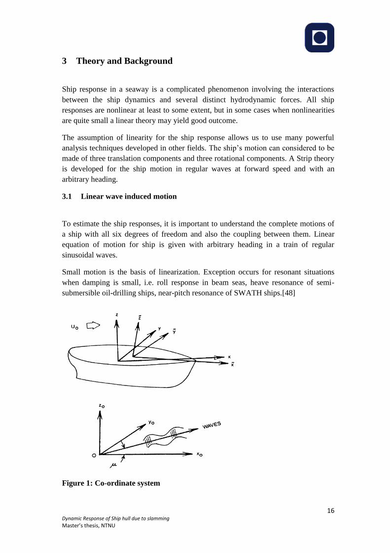
Figure 1: Co-ordinate system
Page 19
17 Dynamic Response of Ship hull due to slamming
Master’s thesis, NTNU
Linear equations in six degrees freedom using body axes in general form is given by,
(1)
∆jk= Generalized inertia matrix component for the ship
d2/dt
2 (Ƞk)= acceleration in mode k
Fj= Total forces and moments acting on the body.
In the above equation for J= 1, 2, 3 are the force equations and j=4,5,6 are the moment
equations.
If equation 1 is written in Euler’s equation of motion (with only fluid forces and
gravitational forces acting on the ship) results in
(2)
FGj =Component of gravitational force
FHj =Component of fluid frce acting on the ship.
In linear theory ship response is linear (i.e. directly proportional with to) wave
amplitude and happens at the frequency as the incident wave.
Gravitational forces simply refer to the weight of the vessel acting at the COG
normally cancels by the buoyant forces. Hydrodynamic and hydrostatic forces are
obtained by integrating the fluid pressure within the underwater part of the hull. Fluid
force equation is given by
(3)
P= Fluid pressure which is calculated by Bernoulli’s equation.
S= under water hull surface area.
Pressure includes both the hydrodynamic and hydrostatic part. Net hydrostatic force
acting on ship in any direction due to a unit displacement is given by the hydrostatic
coefficients. Total velocity potential is needed to find the hydrodynamic force acting
on a ship. Hydrodynamic force which is resulted from the incident and diffracted
waves is called exciting force. Hydrodynamic force which is resulted from radiated
waves are related to added mass and damping. First part of Exciting force may easily
calculated by integrating the incident velocity potential over the body surface. For the
Page 20
18 Dynamic Response of Ship hull due to slamming
Master’s thesis, NTNU
second component of exciting force diffraction potential is integrated over the surface
of the hull.[48]
Figure 2: Super position wave excitation, added mass, damping and restoring
loads
Radiation forces are the unsteady hydrodynamic force component. Radiation force is
effectively a transfer function from unit motion. Added mass which is a apparent
mass- added to the mass of the ship likewise damping is the hydrodynamic force on
the body (in phase with the velocity). [48]
Linearized equation of motion is given by
(4)
3.1.1 Added mass and damping terms
Force harmonic rigid body motions result added mass and damping loads which are
steady state hydrodynamic forces and moments. There is total 36 damping and 36
added mass coefficient. If the structure has zero forward speed and there is no current
it can be shown that coupled added mass and damping coefficient for any two motion
of ship is always same(For example A13=A31 and B15=B51). A finite amount of water
oscillates rigidly connected to the body is not the true concept for understanding
added mass. Added mass should better be understood from hydrodynamic pressure
induced forces point of view.
Added mass and damping coefficient are dependable on the frequency and also
motion mode (for example added mass is not same for sway and heave with same
frequency). Added mass moment fairly depend upon the choice of axes of rotation.
For a ship added mass and damping co efficient normally calculated based on strip
theory. The principle is to divide the underwater part of the ship into several strips.
Page 21
19 Dynamic Response of Ship hull due to slamming
Master’s thesis, NTNU
Two dimensional coefficients are calculated first for each strip and get combined
afterwards. In strip theory flow variation in cross –sectional plane is considered much
larger than the flow variation in longitudinal direction. Damping coefficient and
added mass Co efficient can be fairly dependent on the body shape. Conformal
mapping or source technique is used for two dimensional ship sections. When a body
comes close to the free-surface, a wall or another body added mass value will be
influenced. [49]
There is significant effect on added mass and damping coefficient due to forward
speed structure or current. Ship forward speed is related to the frequency of
encounter. Complete three dimensional realizations of linear wave-induced motion
and loads at forward speed are problematical. For practical purpose strip theory still
plays a good role even it does not account all the physical effects. It is better to know
the limitations to work with strip theory- this is basically a high frequency theory
stands more applicable in head and bow sea than the flowing and quarting sea for a
ship with forward speed. Strip theory is also limited to the ships with low length to
beam ratios.
3.1.2 Restoring forces and moments
For a free floating body, restoring forces follow from hydrostatic and mass
considerations.
Force and moments components may be written as
(5)
Non- zero coefficients for X-Z plane of symmetry for submerged volume in heave is
given by (6)
AWP= water plane area
To assess the amplitude of motion of ship- natural or resonance periods, damping
level and wave excitation level are important parameter. Large motion is expected if
the ship is excited with oscillation periods in the vicinity of a resonance period.
Implication of linear theory for specific vessel response (heave in head sea) illustrated
below.
3.1.3 Heave in irregular waves
Heave response in irregular waves which non-dimensional response is always unity at
zero wave frequency and trends to be zero for high frequency. As frequency
Page 22
20 Dynamic Response of Ship hull due to slamming
Master’s thesis, NTNU
approaches zero wave length become infinite- ship just follows the wave surface,
hence the heave and wave amplitude become equal. On the other hand wave length
becomes small as the wave frequency increases; that is , become ripples to which
ships do not respond. A typical shape of heave response operator at fixed forward
speed with varying wave spectra given below. [48]
Figure 3: Heave response in irregular long-crested head waves
3.1.4 Linear time-domain response
There are some scenarios where transient response accounted. Examples of transient
responses are waves generated by a passing ship, coupling between nonlinear sloshing
in a ship tank and ship motions wet deck slamming on a catamaran in regular incident
waves. Transient Vertical force that excites transient response in heave, pitch, and
global elastic vibration modes are resulted from wet deck slamming. For example we
can consider two-node vertical bending mode that has a natural period on the order of
1 s. Ship response at the wave encounter period which is order of 10 s. There is a
conflict of which frequency we should use in calculating added mass and damping.
For these two different periods the added mass and damping will be quite different.
Page 23
21 Dynamic Response of Ship hull due to slamming
Master’s thesis, NTNU
Here we limit ourselves to heave and pitch. Linear equation of motion may be written
as
(7)
A JK(∞) = mean infinite-frequency added mass coefficient
B JK(∞)=mean infinite-frequency damping coefficient
(8)
hJK (t)= retardation functions (also referred to as impulse response functions)
Page 24
22 Dynamic Response of Ship hull due to slamming
Master’s thesis, NTNU
AJK and BJK behave asymptotically for large frequencies which is difficult to estimate.
Boundary Element Method (BEM) will be good tool to tackle this situation. Hul
surface is approximated by panels. Response calculation is influenced by the high-
frequency behavior of AJK and BJK. [49]
3.1.5 Wave Loads
Wave loads may be needed for structural design purposes from two different aspects:
1. Instantaneous local hydrodynamic pressures on the hull surface due to ship
motions and ship-wave interactions. These pressures may be needed over the
entire hull surface or only on some portion of it. Slamming (water impact) is
the important case.
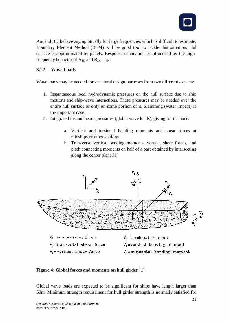
2. Integrated instantaneous pressures (global wave loads), giving for instance:
a. Vertical and torsional bending moments and shear forces at
midships or other stations
b. Transverse vertical bending moments, vertical shear forces, and
pitch connecting moments on half of a part obtained by intersecting
along the center plane.[1]
Figure 4: Global forces and moments on hull girder [1]
Global wave loads are expected to be significant for ships have length larger than
50m. Minimum strength requirement for hull girder strength is normally satisfied for
Page 25
23 Dynamic Response of Ship hull due to slamming
Master’s thesis, NTNU
scantlings obtained from local strength requirements (of plates and stiffeners due to
lateral pressure). [1]
3.2 Second order Non-linear problems
To solve non-linear wave –structure problem in ship hydrodynamics, perturbation
analysis is the most common way. In linear analysis, body boundary condition and
free-surface condition are satisfied on the submerged surface and mean position of the
free surface respectively. In second order theory, the fluid pressure being same to the
atmospheric pressure on instantaneous position of the free surface to accounted the
nor-linearities in the velocity of fluid particle the free surface. We consider all the
terms which are linear to the wave amplitude or square to the wave amplitude. For
irregular seas, the second order loads are sensitive to the wave frequency range with
significant wave energy. To calculate mean wave (drift) forces and moment direct
integration method or maruo’s formula may use. Added mass resistance is sensitive to
the mean wave period. Added resistance curve has a very distinct peak around heave
and itch resonance for a ship at finite Froude number. Viscous effect has contribution
to the wave drift force when they small. Consideration of second order non-linear
problems is important for several marine structures like the design of mooring and
thruster systems, analysis of offshore loading systems, evaluation of towing of large
gravity platforms from the fabrication site to the operation site, added resistance of
ships in waves, performance of submarines close to the free surface and analysis of
slowly oscillating heave, pitch and roll of large volume structures with low water
plane area. [48]
3.3 Wave Impact Loads
Slamming (water impact) load has great importance in structural design .The
probability of slamming is found by defining a threshold relative impact velocity of
slamming occurrence. This threshold is not related to threshold velocity. There is no
threshold for slamming as a physical process. TO come up with good understanding
about slamming threshold it is necessary to study theoretical models or perform
experiments on water impact against wet deck and hull structures of ship and also
necessary in order to develop rational criteria for operational limits due to slamming.
The criteria should be related to slamming loads used in the structural design i.e.
structural response due to slamming. [1]
Page 26
24 Dynamic Response of Ship hull due to slamming
Master’s thesis, NTNU
3.3.1 Consequence of Slamming
1. Compressibility of water, i.e. initial acoustic phase, typically for short time
duration
2. Air-cushion/bubbles, i.e. air cavities can be entrapped and oscillate due to air
compressibility (the cavity is exaggerated in the sketch). Relevant for β<2-
3deg. [50]
3. Hydro-elasticity, i.e. coupling of the hydrodynamic and structural problems,
relevant for β<5 deg. and when the loading time associated with water entry is
small or comparable to the natural wet period of the structure (NB: the
structure does not have only one natural period, typically the highest natural
period is relevant but one can not exclude that also other natural periods could
be excited and matter). Hydro-elasticity means that the hydrodynamic loads
affect the structural elastic vibrations and in return the elastic vibrations affect
the fluid flow and related pressure field. At the beginning the pressure is the
slamming pressure and then it oscillates as a consequence of the coupling. [50]
4. Cavitation, i.e. when local water pressure equals the vapour pressure pvap and
liquid becomes gas. This can happen for instance if hydro-elastic behaviour is
excited because we are close to the free surface so the hydrostatic pressure is
small and the pressure can oscillate greatly due to hydro-elasticity and become
lower than pvap. [50]
5. Ventilation, i.e. when local water pressure goes below the atmospheric
pressure pa and air is attracted between the structure and the water. It can
occur in connection with hydro- elasticity. Another example of occurrence is
in connection with asymmetric impacts with vortex shedding leading to high
local velocities and so low static pressures [50]
In terms of physical effects connected with slamming, we can say
1. Gravity effects are not relevant because the involved fluid accelerations are
typically much larger than gravity acceleration g, e.g. even 200g.
2. Froude number is very important because fixes the impact velocity, i.e. Froude
scaling must be respected when doing in model tests. [50]
3. Viscous effects, i.e. Reynolds number, are of secondary importance because
the time scales involved in the slamming are too short for them to matter.
Page 27
25 Dynamic Response of Ship hull due to slamming
Master’s thesis, NTNU
4. Some effects are relevant in specific cases, e.g. for tanks: boiling for LNG
tanks, mixtures of liquid and gas, ambient (ullage) pressure in case of air
cavities entrapment, ambient (ullage) density [50]
5. The relevance of some effects has not been fully clarified yet, like: surface-
tension effects, though they are expected to be of minor importance; sound
speed, i.e. acoustic effects, though it is expected to be of secondary
importance. [50]
Wetdeck Slamming
Wet deck is defined as the lowest part of the cross-structure connecting two adjacent
side hulls of a multihull vessel. In head sea conditions wetdeck slamming is likely to
occur for a vessel with forward speed. An example of wedge shaped wet deck with
cross section with dead rise angle βW. In some cases it might be zero. If the side hulls
come out of the water as a consequence of the relative vertical motions between the
vessel and the water surface, subsequent slamming on the side hulls expected to
occur.[1]
Figure 5: Wet deck slamming [1]
Local slamming loads depend upon the impact velocity VR . When β is larger than
about 5◦, the maximum slamming pressure is proportional to V2
R for constant VR. In
righthand side of figure 5 – it shows a steep wave impacts on the hull and the relative
small angle βR between the impacting free surface and the hull surface. The presence
of roll can decrease βR and thereby cause increased slamming loads. The slamming
loads are sensitive to βR, when the angle βR is small.[1]
Green Water on deck.
Green water on deck happens as a consequence of “dive-in” in following seas,
especially at reduced speed in large waves and when the frequency of encounter
becomes small. It can also happen as a consequence of large relative vertical motions
Page 28
26 Dynamic Response of Ship hull due to slamming
Master’s thesis, NTNU
between the vessel and the water. The water can enter the deck as a plunging breaker,
causing slamming loads on the deck.
3.3.2 Effect of slamming
Slamming causes with both local and global effect. Whipping is referred as the global
effect of slamming. Hydro elasticity may be important for global loads and also have
some local effects in the case of very high slamming pressures of very short duration.
When the angle between the impacting free surface and hull surface is small, very
high pressures may occur. Hydro-elasticity means that the fluid flow and the
structural elastic reaction are considered simultaneously and that we have mutual
interaction, that is,[1]
-The elastic vibrations cause a fluid flow with a pressure field
-The hydrodynamic loading affects the structural elastic vibrations
In conventional Structural analysis (without hydro-elasticity or dynamic effects),
hydrodynamic loading is considered as rigid structure. The loading is applied in a
quasi-steady manner when the resulting static structural elastic and plastic
deformations and stresses are calculated. Many physical features, such as
compressibility and air cushions affect the fluid flow. Solution of complete
hydrodynamic problem is quite complex and approximation must be made. For
simplification we can neglect the compressibility of the water. It seems very high
slamming pressures are not important for steel and aluminum structures. As the high
pressure peaks are localized in time and space. The force impulse that is important for
the structural response.[1]
3.3.3 Local hydro-elastic slamming effects
Different physical effects occur during slamming generally effects of viscosity and
surface tension are negligible. Air cushion may be formed between the body and the
water if the local angle between the water surface and the body surface is small at the
impact position. Compressibility influences the flow of the air in the cushion. The
airflow interacts with the water flow. When the air cushion collapses, air bubbles are
formed. Local dynamic hydro-elastic effects may occur when the angle between the
water surface and body surface is small. Vibrations lead to subsequent cavitations and
ventilations. The effect of compressibility on maximum local stress is likely to
become small. [1]
Page 29
27 Dynamic Response of Ship hull due to slamming
Master’s thesis, NTNU
Free vibration phase of hydro-elastic slamming
Theoretical study has been done assuming 2D beam theory for strips of the plates.
The whole plate is assumed as wetted and the structure is represented as euler beam
model and it is considered that load levels do not cause plastic deformation. [1]Beam
equation of motion is given by
(9)
P= Hydrodynamic pressure that is a function of the beam deflection
In free vibration phase slamming pressure is zero. But the pressure comes as a
consequence of vibration i.e. added mass effect is considered. The solution is given
by
(10)
The dry normal modes are a good approximation of the wet normal modes when the
added mass distribution is similar to the mass distribution.[1]
3.3.4 Slamming on rigid bodies
When the local angle at impact position between the water surface and the body
surface is not very small, slamming pressures can be used in a static structural
response analysis to find local slamming-induced stresses. [1]In hydrodynamic
calculations body can be assumed as rigid body. Irrotational and compressible water
can b assumed. Air flow is negligible. Local flow acceleration is large relative to
gravitational acceleration when slamming pressure is considered. Theoretical studies
are done assuming 2D vertical water entry of a symmetric body. An indicator of the
importance of 3D flow effects is the ratio 64/π4 ≈ 0.66 between maximum pressures
during water entry of a cone and a wedge with constant velocity and small dead rise
angles [51]
There are two methods for study of slamming impact.
Wagner method
Von Karman Method
Page 30
28 Dynamic Response of Ship hull due to slamming
Master’s thesis, NTNU
Von Karman method neglects the local up rise of the water, whereas aWagner method
accounts for that. Wagner method assumes impact of a blunt body. Beukelman (1991)
showed on basis of experimental results for three-dimensional models that forward
speed has a strong influence on the pressure level when the deadrise angle was lower
than≈2◦.It is difficult numerically to handle the intersection between the body and the
free surface for small local deadrise angles considering exact nonlinear free-surface
conditions are used. The numerical solution is very much influenced by small
intersection angle between the free surface and the body and may cause large errors in
the predictions of the intersection points and destroy numerical solution. The 2D
boundary element method (BEM) by Zhao and Faltinsen (1993) tackled this by
introducing a control surface normal to the body surface at the spray root which may
apply to a broad class of body shapes as well as time-varying water entry velocity.
When it comes to 3D geometry, forward speed with incident waves, and ship-
generated steady and unsteady waves make it complicated (impact analysis) to a
situation that does not seem feasible to solve numerically.[1]
Pressure distribution
Numerical result for water entry of rigid wedges with constant entry velocity was
presented by Zhao and Faltinsen (1993) for 4◦< β < 81◦. Figure 6 shows the predicted
pressures for 20◦ ≤ β ≤ 81◦. In the distribution curve, for β ≤ 20◦ it become
pronouncedly peaked and concentrated close to the spray root. As the angle goes
smaller, sensivity to pressure increases. [1]
Page 31
29 Dynamic Response of Ship hull due to slamming
Master’s thesis, NTNU
Figure 6: Prediction of pressure distribution during water entry of a rigid wedge
Maximum pressure occurs at the apex (or keel) when β >45 deg. For larger angles and
low impact velocities, other pressure contributions may be as important as the
slamming part. The position and value of the maximum pressure, the time duration,
and the spatial extent of high slamming pressures are the parameters that
characterized the slamming load on rigid body with small dead rise angle. [1]
Figure 7: Slamming pressure parameters during water entry of a blunt 2D rigid
body.
Page 32
30 Dynamic Response of Ship hull due to slamming
Master’s thesis, NTNU
The free-surface conditions are approximated as Wagner (1932) did in the outer flow
domain, that is, not for the details at the spray roots. The wetted body surface is found
by integrating in time the vertical velocity of the fluid particles on the free surface and
determining when the particles intersect with the body surface. This is done by
predetermining the intersection points on the body and then determining the time to
reach these points in a time-stepping procedure. Because the velocity in the
generalized Wagner method is singular at the body-water surface intersection, special
care is shown by using a local singular solution. Direct pressure integration is used to
predict the water entry force. [1]
Water entry force
Theoretical slamming force due constant water entry velocity for wedge is given
below.
Figure 8: The vertical slamming force on symmetric wedge
Different methods are used and related to an exact solution of the potential flow
incompressible water entry problem without gravity. For small dead rise angle
Wagner’s flat plate approximation stands quite well. A von Karman type of solution
clearly under predicts the force for β < ≈30◦ to 40◦[1]
Page 33
31 Dynamic Response of Ship hull due to slamming
Master’s thesis, NTNU
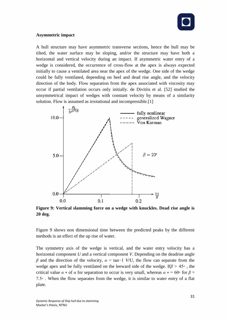
Asymmetric impact
A hull structure may have asymmetric transverse sections, hence the hull may be
tilted, the water surface may be sloping, and/or the structure may have both a
horizontal and vertical velocity during an impact. If asymmetric water entry of a
wedge is considered, the occurrence of cross-flow at the apex is always expected
initially to cause a ventilated area near the apex of the wedge. One side of the wedge
could be fully ventilated, depending on heel and dead rise angle, and the velocity
direction of the body. Flow separation from the apex associated with viscosity may
occur if partial ventilation occurs only initially. de Divitiis et al. [52] studied the
unsymmetrical impact of wedges with constant velocity by means of a similarity
solution. Flow is assumed as irrotational and incompressible.[1]
Figure 9: Vertical slamming force on a wedge with knuckles. Dead rise angle is
20 deg.
Figure 9 shows non dimensional time between the predicted peaks by the different
methods is an effect of the up rise of water.
The symmetry axis of the wedge is vertical, and the water entry velocity has a
horizontal component U and a vertical component V. Depending on the deadrise angle
β and the direction of the velocity, α = tan−1 V/U, the flow can separate from the
wedge apex and be fully ventilated on the leeward side of the wedge. Ifβ > 45◦ , the
critical value α ∗ of α for separation to occur is very small, whereas α ∗ = 60◦ for β =
7.5◦ . When the flow separates from the wedge, it is similar to water entry of a flat
plate.
Page 34
32 Dynamic Response of Ship hull due to slamming
Master’s thesis, NTNU
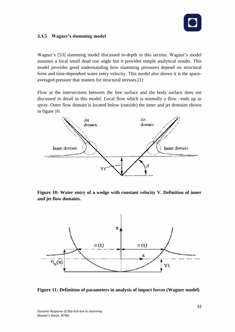
3.3.5 Wagner’s slamming model
Wagner’s [53] slamming model discussed in-depth in this section. Wagner’s model
assumes a local small dead rise angle but it provides simple analytical results. This
model provides good understanding how slamming pressures depend on structural
form and time-dependent water entry velocity. This model also shows it is the space-
averaged pressure that matters for structural stresses.[1]
Flow at the intersections between the free surface and the body surface does not
discussed in detail in this model. Local flow which is normally a flow –ends up as
spray. Outer flow domain is located below (outside) the inner and jet domains shown
in figure 10.
Figure 10: Water entry of a wedge with constant velocity V. Definition of inner
and jet flow domains.
Figure 11: Definition of parameters in analysis of impact forces (Wagner model)
Page 35
33 Dynamic Response of Ship hull due to slamming
Master’s thesis, NTNU
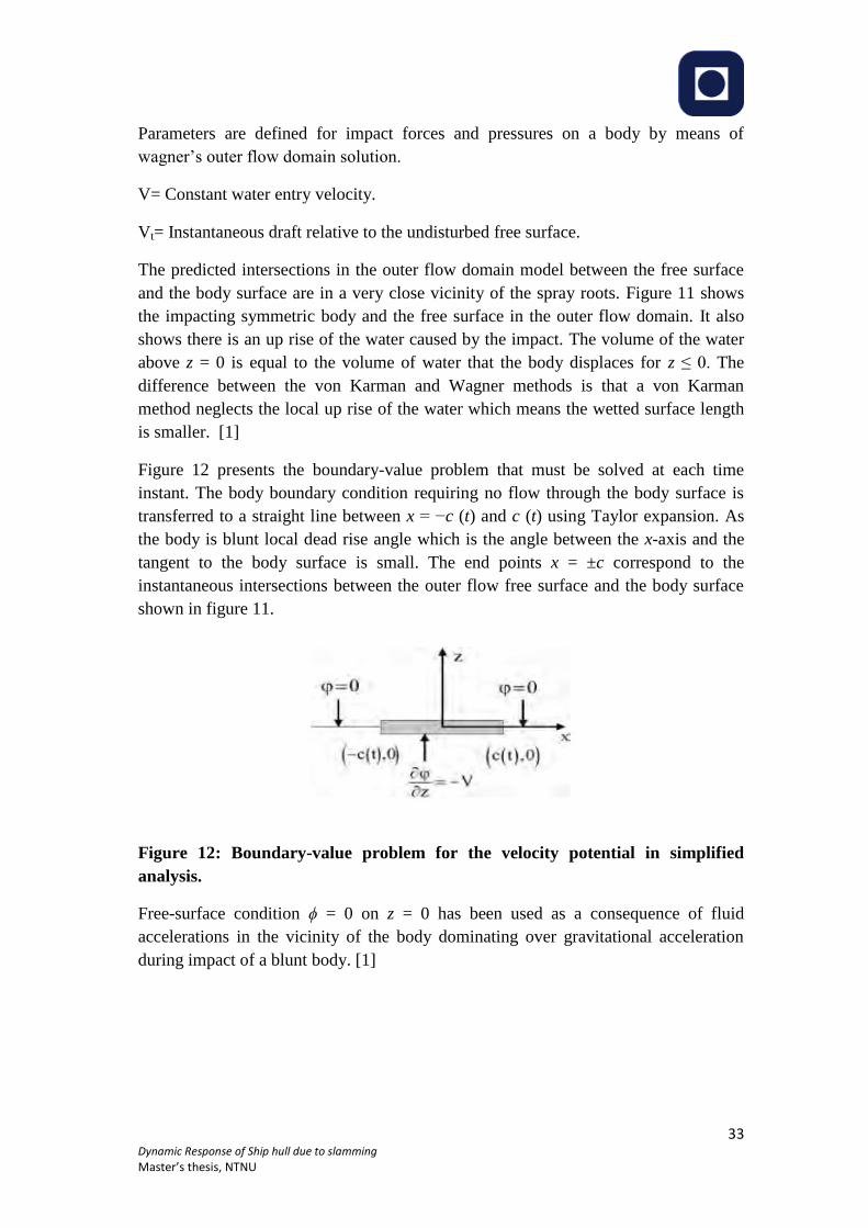
Parameters are defined for impact forces and pressures on a body by means of
wagner’s outer flow domain solution.
V= Constant water entry velocity.
Vt= Instantaneous draft relative to the undisturbed free surface.
The predicted intersections in the outer flow domain model between the free surface
and the body surface are in a very close vicinity of the spray roots. Figure 11 shows
the impacting symmetric body and the free surface in the outer flow domain. It also
shows there is an up rise of the water caused by the impact. The volume of the water
above z = 0 is equal to the volume of water that the body displaces for z ≤ 0. The
difference between the von Karman and Wagner methods is that a von Karman
method neglects the local up rise of the water which means the wetted surface length
is smaller. [1]
Figure 12 presents the boundary-value problem that must be solved at each time
instant. The body boundary condition requiring no flow through the body surface is
transferred to a straight line between x = −c (t) and c (t) using Taylor expansion. As
the body is blunt local dead rise angle which is the angle between the x-axis and the
tangent to the body surface is small. The end points x = ±c correspond to the
instantaneous intersections between the outer flow free surface and the body surface
shown in figure 11.
Figure 12: Boundary-value problem for the velocity potential in simplified
analysis.
Free-surface condition ϕ = 0 on z = 0 has been used as a consequence of fluid
accelerations in the vicinity of the body dominating over gravitational acceleration
during impact of a blunt body. [1]
Page 36
34 Dynamic Response of Ship hull due to slamming
Master’s thesis, NTNU
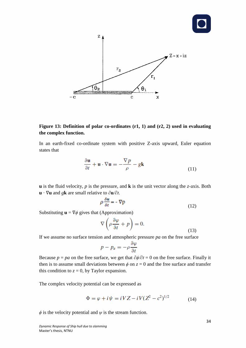
Figure 13: Definition of polar co-ordinates (r1, 1) and (r2, 2) used in evaluating
the complex function.
In an earth-fixed co-ordinate system with positive Z-axis upward, Euler equation
states that
(11)
u is the fluid velocity, p is the pressure, and k is the unit vector along the z-axis. Both
u · ∇u and gk are small relative to ∂u/∂t.
(12)
Substituting u = ∇ϕ gives that (Approximation)
(13)
If we assume no surface tension and atmospheric pressure pa on the free surface
Because p = pa on the free surface, we get that ∂ϕ/∂t = 0 on the free surface. Finally it
then is to assume small deviations between ϕ on z = 0 and the free surface and transfer
this condition to z = 0, by Taylor expansion.
The complex velocity potential can be expressed as
(14)
ϕ is the velocity potential and ψ is the stream function.
Page 37
35 Dynamic Response of Ship hull due to slamming
Master’s thesis, NTNU
Complex velocity is given by
(15)
Introducing Z− c = r1eiθ1 and Z+ c = r2eiθ2 , where θ1 and θ2 vary from −π to π
We can write θ1 = −π and θ2 = 0 when |x| < c and z = 0−
When x > c and z = 0, both θ1 and θ2 are zero
For x < −c and z = 0 means that θ1 = θ2 = π
For, ϕ = 0 for |x| > c on z =0
Velocity potential can be written as
Pressure equation can be written as
(16)
The first term is denoted as the slamming pressure.
It is associated with the rate of change of the wetted surface which is
approximately2dc/dt.
The two-dimensional vertical force acting on the impacting body can be expressed as
Page 38
36 Dynamic Response of Ship hull due to slamming
Master’s thesis, NTNU
(17)
The term ρπc2/2 appearing in the last term is the two-dimensional added mass in
heave a33
(18)
Second term in the above equation is the slamming force. This is a common way to
express the slamming force in connection with the von Karman method.[1]
3.3.6 Design pressure on rigid bodies
If the dead rise angle is small, one should not put too much emphasis on the peak
pressures. It is the pressure integrated over a given area that is of interest in structural
design as long as hydro elasticity does not matter. When hydro-elasticity matters,
maximum pressures cannot be used to estimate structural response. [1]
For better illustration of average pressures appropriate for the design of a local rigid
structure, we can consider a structural part shown on the following figures.
Figure 14: Water entry of a wedge shaped elastic cross section
Page 39
37 Dynamic Response of Ship hull due to slamming
Master’s thesis, NTNU
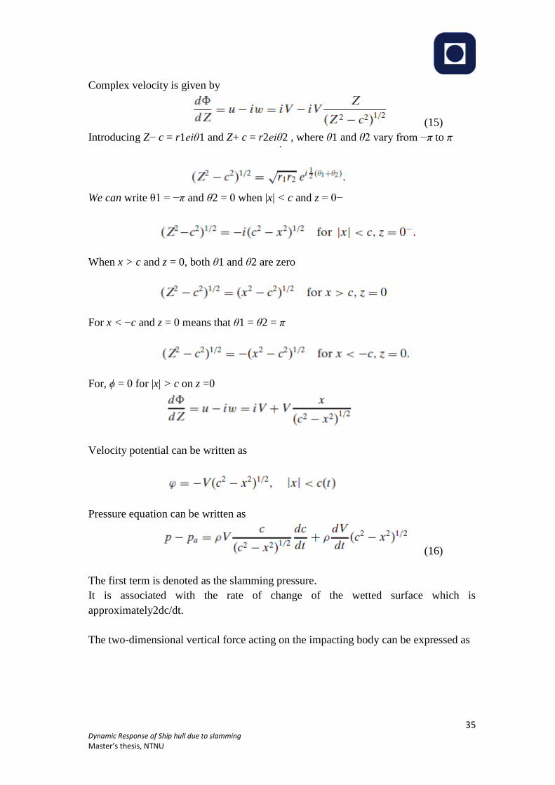
Figure 15: Stiffened panel consisting of plate and longitudinal stiffener.
By assuming the transverse frame to be much stiffer than the longitudinal stiffener,
the resulting stresses in the longitudinal stiffener are normally more important than
those in the transverse frame. If the x-direction means the longitudinal direction of the
ship, the instantaneous slamming pressure does not vary much with the position x
between two transverse frames. The instantaneous loads of importance for the stresses
in the longitudinal stiffener number i is then the space averaged slamming pressure is
the first approximation yi and yi+1 (Figure 14). This space averaged pressure varies
with time, and it is the largest value that is the prime importance. Wagner’s [53]
solution is used for water entry of a wedge to find the space-averaged pressure
assuming the dead rise angle to be small. The space-averaged pressure from yi to yi+1
has a maximum when c = yi+1. The maximum value is given by,
(19)
Page 40
38 Dynamic Response of Ship hull due to slamming
Master’s thesis, NTNU
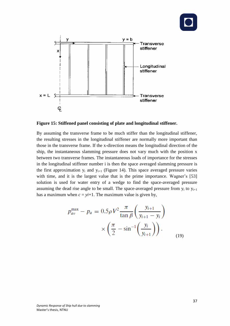
3.3.7 Effect of air cushions on slamming
When a body with a horizontal flat bottom or a small deadrise angle hits a horizontal
free surface, a compressible air pocket is created between the body and the free
surface in an initial phase (Figure 16)
Figure 16: Deformation of the free surface and formation of an air pocket during
entry of a rigid body
ϕ = velocity potential for the water motion,
UT
n = normal velocity of air pocket.
The pressure in the air cushion will in reality deform both the structure and the free
surface. The scenario in Fig 1.13 for an air cushion may have too short a duration for
the detailed behavior to influence the maximum slamming induced structural stresses.
However, air pockets may be created as a consequence of the shape of the impacting
free surface. One scenario could be plunging breaking waves against the ship side.
This causes an air cushion in a 2D flow situation. However, the air has the possibility
to escape in a 3D flow situation. Another scenario is in connection with wet deck
slamming (Figure 16) [1]
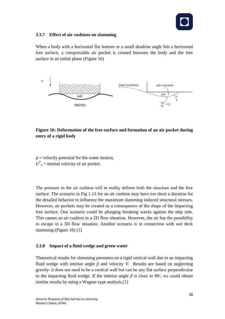
3.3.8 Impact of a fluid wedge and green water
Theoretical results for slamming pressures on a rigid vertical wall due to an impacting
fluid wedge with interior angle β and velocity V. Results are based on neglecting
gravity- it does not need to be a vertical wall but can be any flat surface perpendicular
to the impacting fluid wedge. If the interior angle β is close to 90◦, we could obtain
similar results by using a Wagner-type analysis.[1]
Page 41
39 Dynamic Response of Ship hull due to slamming
Master’s thesis, NTNU
Figure 17: Impact of fluid wedge and green water
First from Left: sketch of the equivalent problem of a fluid (half) wedge impacting a
flat wall at 90◦.
Center: maximum pressure on a wall due to the water impact.
Right: pressure distribution along the vertical wall for 5◦ ≤ β ≤ 75◦ with increment _β
= 10◦.
The results are numerically obtained by neglecting gravity and using the similarity
solution by Zhang et al. [54]
3.3.9 Global wet deck slamming effects
Global structural strength of ship is influenced by the slamming effect. For mono hull
vessels, these effects are associated with bow flare slamming effects. Transient heave,
pitch and global vertical elastic vibrations are excited because of the wet deck
slamming. The dominant elastic vibrations in head sea are in terms of two node
longitudinal vertical bending. The phenomenon is called whipping and also induces
global shear forces, bending moments and stresses.[1]
Page 42
40 Dynamic Response of Ship hull due to slamming
Master’s thesis, NTNU
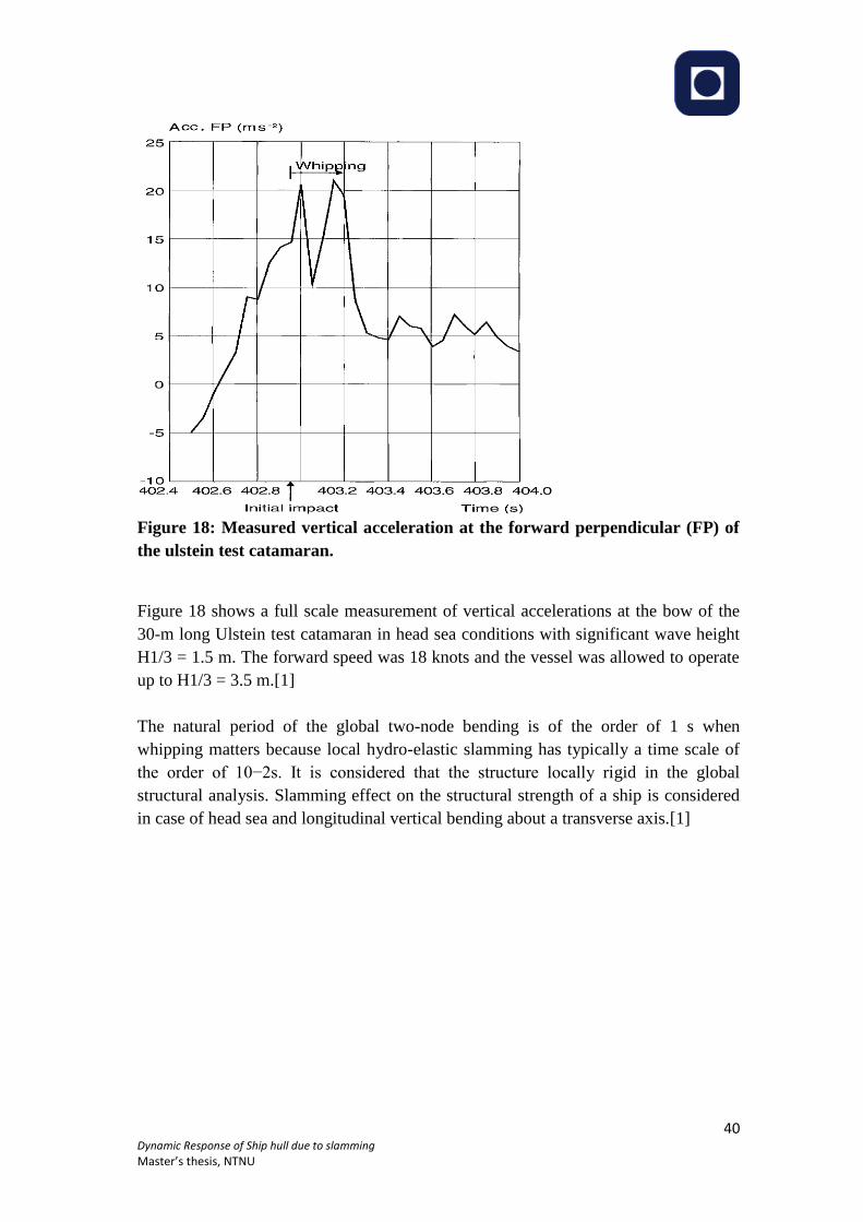
Figure 18: Measured vertical acceleration at the forward perpendicular (FP) of
the ulstein test catamaran.
Figure 18 shows a full scale measurement of vertical accelerations at the bow of the
30-m long Ulstein test catamaran in head sea conditions with significant wave height
H1/3 = 1.5 m. The forward speed was 18 knots and the vessel was allowed to operate
up to H1/3 = 3.5 m.[1]
The natural period of the global two-node bending is of the order of 1 s when
whipping matters because local hydro-elastic slamming has typically a time scale of
the order of 10−2s. It is considered that the structure locally rigid in the global
structural analysis. Slamming effect on the structural strength of a ship is considered
in case of head sea and longitudinal vertical bending about a transverse axis.[1]
Page 43
41 Dynamic Response of Ship hull due to slamming
Master’s thesis, NTNU
Figure 19: Position of slamming on the wet deck in regular head sea waves as a
function of wave lenght.
Page 44
42 Dynamic Response of Ship hull due to slamming
Master’s thesis, NTNU
The figure shows a longitudinal cross section at the centerplane of the catamaran. The
bow ramp is seen in the fore part. Fn = 0.5, ζa = ζslam = lowest incident wave
amplitude when slamming occurs, L= LPP = length between perpendiculars. Figure
19 show that the longer the wavelengths are, the closer to the bow the initial impact
occurs. The figure also presents the minimum wave amplitude ζa for slamming to
occur for a given incident wavelength. This minimum wave amplitude is smallest for
λ/L=1.26 for the current cases. The smaller the minimum wave amplitude, the larger
the amplitude of the relative vertical motion divided by ζa. When the water does not
initially hit at the end of the forward deck, the water surface has to be initially
tangential to the wet deck surface at the impact position.[1]
3.3.10 Water entry and exit loads
Both the water entry and water exit phases is the concern in The global slamming
analysis. This is the combination of both wagner and Von karman method.
Assumptions:
- Incident regular head sea waves act on a catamaran at forward speed
- The wet deck has a plane horizontal transverse cross section
In Von Karman method wetted area can be found by examining the relative vertical
displacement
(20)
h(x)= time-independent wet deck height above calm water
ȠB(x,t)= vertical ship motion, which includes global elastic vibrations in addition to
rigid body heave and pitch motions. For Ƞx is less than zero slamming occurs.
Figure 20:2D boundary value problem for velocity potential due to wet deck
slamming
a(t), b(t) and l(t) are ship fixed x-coordinates. X-Z is the local 2D coordinate system
on the wetted part of the deck.
Page 45
43 Dynamic Response of Ship hull due to slamming
Master’s thesis, NTNU
Figure 20 shows the boundary value problem that we have to solve at each time
instant to find the velocity potential _ due to slamming
Here ȠB = Ƞ3 − xȠ5 and ∂ȠB/∂x = −Ƞ5 in the case of no global elastic vibrations. The
second term is the velocity component of U normal to the wet deck. The angle τ
expresses the local geometry, for example, due to the bow ramp and also includes the
trim due to hydro-elastic and steady forward speed dependent hydrodynamic forces
on the vessel in calm water. There is also a contribution from the time averaged non-
linear hydrodynamic loads due to unsteady wave body interaction. The former effect
is normally neglected.[1]
As the wetted length is small relative to the incident wavelength, so we can do the
approximation,
This follows by keeping the constant and linearly varying terms of a Taylor expansion
of VR about X = 0 as the flow associated with V2X in is anti-symmetric about X = 0, V2
does not contribute to the vertical force.
Figure 21: Outline of the experimental hull arrangements (top view) ( Ge 2002)
Froude-kriloff and hydrostatic forces on the wet deck will also contribute, which are
generally smaller than the slamming and added mass forces. Assuming that the
incident free-surface ζ = ζa sin (ωet − kx) is higher than ηB + h(x), buoyancy” force is
given by
(21)
Page 46
44 Dynamic Response of Ship hull due to slamming
Master’s thesis, NTNU
3.3.11 Three-body model
Ge et al. [55] studied numerically and experimentally wet deck slamming induced
global loads on a catamaran in head sea deep-water egular waves. The model is
shown in figure 21. Theoretically the pre-mentioned vessel can be modeled as three
rigid bodies with longitudinal connections of elastic beams as shown in the figure 22
below.
Figure 22: Degrees of freedom of segmented model
The general equation system for the motion of the hull segments can be expressed as
r= displacement matrix of this six degrees- of-freedom system, containing the heave
and pitch for each segment
Mgen= Mass matrix, mass refers to both the segment mass and the added mass
Bgen= damping matrix
Kgen= restoring (stiffness) matrix, including the hydrostatic restoring terms from the
ship segments as well as the coupling terms from the spring beams
Fgen= forces due to wet deck slamming and linear wave excitation loads on the side
hulls
The static beam equation with zero loading is
EI. d4w/dx
4 = 0,
Figure 23:Elastic connection between two adjacent rigid body segments
Page 47
45 Dynamic Response of Ship hull due to slamming
Master’s thesis, NTNU
The connecting beam AB between body 1 and body2 is used to illustrate the
procedure (Figure 23). x=0 and L correspond to, respectively, point A and point B.
Integrating above equation
The boundary conditions of the beam require that the vertical and rotational
displacements at the ends of A and B match those at the adjacent ends of body 1 and
body 2, so
Figure 24: Illustration of rotational sign for and adjacent bodies
The longitudinal distribution of vertical shear force Q(x) and bending moment M(x) at
the right hand side of the beam element
at x=0 and L, the loads acting on the three rigid bodies due to the connecting beams
can then be expressed as
(22)
Page 48
46 Dynamic Response of Ship hull due to slamming
Master’s thesis, NTNU
There are six degrees of freedom and thus six pairs of eigenmodes and frequencies.
The two lowest modes with lowest natural frequencies are the coupled heave and
pitch modes. The important stiffness of these modes are the result of the hydrostatic
restoring coefficients.[1]
The third and fourth modes are the two node and three node bending modes in the
longitudinal vertical plane and are illustrated in figure 25,
Figure 25: Calculated shapes of eigen modes for 3-body model.
The illustration is based on a finite element model, which is really not necessary for
finding the required modes for a segmented model such as this. However a finite
element model is needed to find the modes for a real ship. The fifth and sixth modes
have very high natural frequencies relative to the other modes and are in reality highly
structurally damped.
Steady-state experimental and numerical vertical shear force (VSF) and vertical
bending moment (VBM) at cut 1 in regular head sea waves for the most severe
slamming case obtained for the model presented in figure 26. . The dominant
contributions are the result of the two node bending mode, but there are also
noticeable rigid-body effects. The Froude number is Fn =0.29, the wave period is
T=1.8 s and the incident wave amplitude is 0.041 m.[1]
Page 49
47 Dynamic Response of Ship hull due to slamming
Master’s thesis, NTNU
Figure 26: Comparison between experimental and numerical value.
3.3.12 Global Hydro-elastic effects on mono-hulls
Beam equations are considered to describe the global hydroelastic effects on
monohulls. Timoshenko model accounts for the shear deformation and rotational
inertia, but is more complicated than the Euler beam model and does not predict much
difference when it comes to bending moments. The effect of shear deformation should
be included, especially when higher modes are important.
Figure 27: Ship vibrating with two-node deformation.
w= deformation
The x-axis is in the direction of the inflow velocity U. U = ship speed.
Using Euler beam model
(23)
Page 50
48 Dynamic Response of Ship hull due to slamming
Master’s thesis, NTNU
Assuming that the deformation is small or rather that ∂w/∂x << 1. m(x) is the body
mass per unit length, and EI(x) is the bending stiffness and f3 is time-dependent
vertical hydrodynamic force per unit length. The end conditions are zero shear force
and bending momentat the forward and aft ends of the ship.
at the end of the ship.
First we neglect excitation and express the contributions to f3 due to linear hull
vibrations. We are interested in oscillations with clearly higher frequencies than
typical frequencies of encounter due to incident waves, it is appropriate to use the
free-surface condition ϕ = 0 on the mean free surface z = 0. ϕ satisfies the 2D Laplace
equation in the transverse cross-sectional plane of the ship. The vibrations cause a
local angle ∂w/∂x of the ship relative to the x axis. This angle implies that the steady
flow with velocity U along the x-axis has a velocity component −U∂w/∂x in the cross-
sectional plane of the vibrating ship. we must account for the vibrating velocity ∂w/∂t
in formulating that there is no flow through the hull surface.[1] Linear body boundary
condition is given by,
(24)
C(x)= mean submerged cross-sectional curve of the hull surface
n =(n1,n2,n3), the normal vector to the hull surface with positive direction into the
fluid
A normalized velocity potential ϕ3 is given by
Linear hydrodynamic pressure on the hull is given by
Hence The 2D vertical force f3 HD
on the hull due to the dynamic pressure
a33 = 2D infinite-frequency added mass in heave.
Introducing the change of buoyancy due to the beam deflection,
Page 51
49 Dynamic Response of Ship hull due to slamming
Master’s thesis, NTNU
(25)
Here b means sectional beam and f3 exc
is the hydrodynamic excitation load per unit
length. Lewis form technique is a simple way to estimate a33. The expression for
infinite frequency is
Where
Figure 28: 2D added mass in heave for Lewis form sections
The diagram given above is considering the frequency of oscillation.[1]
A = cross-sectional area, B = beam, D = draft, ϕ = velocity potential.
Page 52
50 Dynamic Response of Ship hull due to slamming
Master’s thesis, NTNU
4 Wave induced responses
The fundamental elements of a vibrating system include the basic mass-elastic
properties as well as damping and exciting forces. In order to control or limit the
vibratory response it is necessary to modify the mass-elastic properties by increasing
the damping, reducing the exciting forces or changing the exciting frequencies.
Increasing the damping may be useful in the solution of local structural vibration
problems and in certain machinery and equipment problems but is not a practical
solution for reducing hull girder vibration. The wave induced response of ships and
floating offshore structures might occur in two different forms denoted as springing
and whipping. Whipping is characterized by transient vibration response caused by
slamming impulses, and springing represents a resonant periodic vibration response to
high frequency harmonic wave excitation components. The analysis methods only for
whipping vibration response are briefly discussed.
4.1 Hull Structural response
Structural model must reflect the hull’s dynamic properties in the frequency range of
interest, i.e. the natural frequencies, the associated mode shapes and, last but not least,
the damping characteristics. Depending on the application a variety of methods is
used for this purpose:
a) Dynamic amplification factors in combination with quasi-static calculations,
b) Analytical formulae valid for impulsively or harmonically excited vibrations of 1-
or 2-DOF systems,
c) Timoshenko beam FE models reflecting one or several hull girder vertical bending
modes,
d) As like as c) but extended to simulate also torsional and horizontal bending
vibration modes,
e) 3D FE models of the complete hull for more complex hull structures, f) as e) but
with local FE mesh refinements for specific assessment purposes, e.g. stress
concentration effects or local deck panel vibration. The prediction methods for wave
induced vibration can be classified in coupled (hydro-elastic) and decoupled
approaches. Decoupled methods neglect the influences of hull elasticity and hull
vibration displacements on the magnitude of the impulsive or harmonic hydrodynamic
pressure excitation forces.
Page 53
51 Dynamic Response of Ship hull due to slamming
Master’s thesis, NTNU
Coupling between hydrodynamic analysis and structural response calculation is
normally realised by integrating the structural model into the hydrodynamic excitation
force analysis. Hull models according c), d), and e) are used for this purpose. In most
applications the hull FE models are replaced by modal representations for the sake of
computation efficiency. Normally, only a few of the first natural modes of the hull
girder are required to describe the dynamic response of the hull with sufficient
accuracy.
4.2 Whipping vibration analysis
Hull whipping response magnitude due to slamming impulses mainly depends on the
strength and location of the slamming impulse. The ratio of the impulse duration to
the natural period of the relevant hull girder vibration mode and the shape of the time
history of the impulsive force determine the grade of dynamic magnification of the
quasi-static response. In structural dynamics the dynamic amplification factor (DAF)
is often used to estimate the dynamic response from the quasi-static response to avoid
elaborate time domain transient response computations. Theoretically, the DAF can
reach a maximum value of 2.0, but for slamming excited hull girder vibration values
between approximately 1.1 and 1.4 are more typical. In order to point out the
difference to the fully decoupled approaches, as, e.g., the DAF concept, some
researchers use the term ‘1-way coupling’ for such a procedure as long as
hydrodynamic and structural response analysis are performed independently, and ‘2-
way coupling’, if also these computations are performed simultaneously, i.e. a hydro-
elastic analysis is performed.[56]
Also the calculation of ship motions, wave loads and slamming pressures can be
performed with simple and efficient or more elaborate and accurate methods. In
combination with the different ways to perform the structural response prediction and
to couple hydrodynamic and structural analysis, there exist a number of options for
the definition of a meaningful overall analysis procedure. [56]
In practice, there will be always a need for a compromise between the accuracy of the
respective approach and its computational efficiency. It goes without saying that the
choice of the most suitable overall procedure will depend on the objective of the
analysis, e.g., it must be differentiated between extreme load scenarios, the
computation of stress range spectra or the prediction of design values based on long-
term statistics.[56]
Whipping effect is currently very difficult to reliably calculate or model.
Classification societies are therefore unable to predict its magnitude or effect on a
ship’s structure, with any confidence, and as a consequence they are not generally
calculated during the structural design process. [56]
Page 54
52 Dynamic Response of Ship hull due to slamming
Master’s thesis, NTNU
4.3 Hull Frequency determination
The most important requirement to minimize hull vibration is to limit the exciting
forces, is to avoid resonance of the hull girder with the frequency of exciting forces.
Here we focus on methods available to calculate hull natural frequencies and
demonstrates a simplified, empirical method that can be used in the preliminary hull
vibration analysis.
4.3.1 Empirical Analysis
In early 1894, Schlick [25] developed an empirical formula based on modification of
an ordinary beam, which approximated fundamental bending frequency. By
introducing empirical factors obtained by systematic shipboard vibration studies, it
was possible to estimate the fundamental vertical frequency of a ship. A study by
Disenbacker and Perkins [26] , demonstrates a further refinement of this simplified
approach, which would provide the natural frequencies of a ship's hull, within ±5% of
that obtained by the more conventional 20-station beam model, which requires a
complete distribution of ship parameters.
4.3.2 20-Station Beam Model
The 20-station beam model, frequently used for preliminary design purposes, was
developed at the David Taylor Research Center [27]. For each station along the length
of a hull, it is necessary to develop the weight, virtual mass, bending rigidity and
shear rigidity. This of course, requires firm design data that is not necessarily
available in the early stages of design, and considerable engineering time to assemble
and calculate. An early digital computer program for solving the system of finite-
difference equations that approximate the problem representing the steady-state
motion of a vibrating beam-spring system, such as a ship hull in bending, was also
developed at DTRC.
4.3.3 Finite Element Model
Primarily ship model is made of finite-elements of beam and plate, with large number
of joints (or nodes) as inter-joining points. With each node having six degrees of
freedoms (DOF), the mathematical model consists of mass and stiffness matrices of
high order. Computations with matrices of such an order of magnitude are very costly
Page 55
53 Dynamic Response of Ship hull due to slamming
Master’s thesis, NTNU
and not warranted to determine hull frequencies. Reduction of matrix size was
therefore undertaken. For determination of the basic hull frequencies however, only
the lowest frequencies are required. The use of the finite-element model analysis
requires the geometry of the structure to be analyzed. In the early design phase, the
detail required for a vibratory response analysis is generally not available. If it is
necessary to make assumptions on the structural details and the boundary conditions,
the accuracy expected of the finite-element analysis is lost and the expense is not
warranted.
4.4 Dynamic Analysis
There are number of different computer programs are available in the market for
dynamic analysis (Free vibration and forced response) of ships and offshore
structures, for instance ABAQUS package, ANSYS, SESAM-DNV package, GL
shipload etc. ABAQUS is one of the most widely used software by wide range of
industries, including aircraft manufacturers, automobile companies, oil companies,
shipbuilding industries and microelectronics industries, as well as national
laboratories and research centers. For this thesis work, ABAQUS is also used for free
vibration analysis and dynamic forced response analysis.
4.4.1 Overview
There are several methods for performing dynamic analysis of problems in which
inertia effects are considered. Modal methods are usually chosen for linear analyses
because in direct-integration dynamics the global equations of motion of the system
must be integrated through time, which makes direct-integration methods significantly
more expensive than modal methods. Subspace-based methods are provided in
Abaqus/Standard and offer cost-effective approaches to the analysis of systems that
are mildly nonlinear.
In Abaqus/Standard dynamic studies of linear problems are generally performed by
using the eigen modes of the system as a basis for calculating the response. In such
cases the necessary modes and frequencies are calculated first in a frequency
extraction step. Eigen mode extraction can become computationally intensive if many
modes are required for a large model. [45]
Page 56
54 Dynamic Response of Ship hull due to slamming
Master’s thesis, NTNU
4.4.2 Implicit Versus Explicit
The direct-integration dynamic procedure provided in Abaqus/Standard offers a
number of implicit operators for integration of the equations of motion, while
Abaqus/Explicit uses the central-difference operator. In an implicit dynamic analysis
the integration operator matrix must be inverted and a set of nonlinear equilibrium
equations that must be solved at each time increment. Displacements and velocities
are calculated in terms of quantities that are known at the beginning of an increment
in an explicit dynamic analysis; therefore, the global mass and stiffness matrices need
not be formed and inverted, which means that each increment is relatively
inexpensive compared to the increments in an implicit integration process. The size of
the time increment in an explicit dynamic analysis is limited, however, because the
central-difference operator is only conditionally stable; whereas the implicit operator
options available in Abaqus/Standard are unconditionally stable and, thus, there is no
such limit on the size of the time increment that can be used for most analyses.
Abaqus/Explicit offers fewer element types than Abaqus/Standard. For example, only
first-order, displacement method elements (4-node quadrilaterals, 8-node bricks, etc.)
and modified second-order elements are used, and each degree of freedom in the
model must have mass or rotary inertia associated with it. [45]
Dynamic, implicit step is used for the response analysis in the work. This steps is used
in the analysis because it provides suitable understanding for
- must be used when nonlinear dynamic response is being studied;
- can be fully nonlinear (general dynamic analysis) or can be based on the
modes of the linear system (subspace projection method); and
- can be used to study a variety of applications, including
- Dynamic responses requiring transient fidelity and involving
minimal energy dissipation;
- Dynamic responses involving nonlinearity, contact, and moderate
energy dissipation; and
- Quasi-static responses in which considerable energy dissipation
provides stability and improved convergence behavior for
determining an essentially static solution
Page 57
55 Dynamic Response of Ship hull due to slamming
Master’s thesis, NTNU
4.4.3 Time integration methods
Abaqus/Standard uses the Hilber-Hughes-Taylor time integration by default unless it
is specified that the application type is quasi-static. The Hilber-Hughes-Taylor
operator is an extension of the Newmark -method. Numerical parameters associated
with the Hilber-Hughes-Taylor operator are tuned differently for moderate dissipation
and transient fidelity applications. The backward Euler operator is used by default if
the application classification is quasi-static.[41]
These time integration operators are implicit, which means that the operator matrix
must be inverted and a set of simultaneous nonlinear dynamic equilibrium equations
must be solved at each time increment. This solution is done iteratively using
Newton's method. The principal advantage of these operators is that they are
unconditionally stable for linear systems; there is no mathematical limit on the size of
the time increment that can be used to integrate a linear system. Marching through a
simulation with a finite time increment size generally introduces some degree of
numerical damping. This damping differs from the material damping. [40]
Default parameters for the Hilber-Hughes-Taylor integrator.
Parameter
Application
Transient Fidelity Moderate Dissipation
–0.05 –0.41421
0.275625 0.5
0.55 0.91421
Table 1: Hilber- Hughes- Taylor integrator parameters[41]
In this process time increment size is specified. This approach is not generally
recommended but may be useful in special cases. The analysis terminates if
convergence tolerances are not satisfied within the maximum number of iterations
allowed.
Page 58
56 Dynamic Response of Ship hull due to slamming
Master’s thesis, NTNU
4.4.4 Damping in dynamic analysis
Every non-conservative system exhibits some energy loss that is attributed to material
nonlinearity, internal material friction, or to external (mostly joint) frictional behavior.
Conventional engineering materials used in ship building industry like steel and high
strength aluminum alloys provide small amounts of internal material damping, not
enough to prevent large amplification at or near resonant frequencies.
4.4.4.1 Source of damping
There are four categories of damping sources: material and element damping, global
damping, modal damping, and damping associated with time integration.
Material damping
Material Rayleigh damping is defined by two Rayleigh damping factors: for mass
proportional damping and for stiffness proportional damping. In general, damping
is a material property specified as part of the material definition. For the cases of
rotary inertia, point mass elements, and substructures, where there is no reference to a
material definition, the damping can be defined in conjunction with the property
references. Any mass proportional damping also applies to nonstructural features
Dashpots, springs with their complex stiffness matrix, and connectors that serves as
dampers, all with viscous and structural damping factors. Viscous damping can be
included in mass, beam, pipe, and shell elements with general section properties.
Global Damping
In cases where material or element damping is not appropriate or sufficient, abstract
damping factors are used to an entire model. Abaqus allowsto specify global damping
factors for both viscous (Rayleigh damping) and structural damping (imaginary
stiffness matrix). [45]
Modal Damping
Modal damping applies only to mode-based linear dynamic analyses which are not
used in the current work.
Page 59
57 Dynamic Response of Ship hull due to slamming
Master’s thesis, NTNU
Damping in a linear dynamic analysis
Damping applied to a linear dynamic system in two ways
- velocity proportional viscous damping
- Displacement proportional structural damping, which is for use in
frequency domain dynamics. The exception is SIM-based transient modal
dynamic analysis, where the structural damping is converted to the
equivalent diagonal viscous damping.[45]
4.4.5 Frequency Extraction procedure
- Eigen value are extracted to calculate the natural frequencies and the
corresponding mode shapes of a system;
- include initial stress and load stiffness effects due to preloads and initial
conditions if geometric nonlinearity is accounted for in the base state, so
that small vibrations of a preloaded structure can be modeled;
- compute residual modes if requested;
- linear perturbation procedure; [45]
4.4.6 Eigen Extraction methods
There are three eigen value extraction methods:
- Lanczos
- Automatic multi-level substructuring (AMS), an add-on analysis capability for
Abaqus/Standard
- Subspace iteration
Lanczos method is used in the eigen value extraction method in the current work.
4.4.6.1 Lanczos Eigen Solver
In Lanczos method it is needed to provide the maximum frequency of interest or the
number of eigen values required. Abaqus/Standard determines a suitable block size. If
you specify both the maximum frequency of interest and the number of eigen values
Page 60
58 Dynamic Response of Ship hull due to slamming
Master’s thesis, NTNU
required and the actual number of eigenvalues is underestimated, In that case
Abaqus/Standard issue a corresponding warning message; the remaining eigen modes
can be found by restarting the frequency extraction. [45]
5 Input Data
This section contains the input from the benchmark committee to develop the ship
model in GeniE. Afterwards exports from GeniE used as input for HydroD and
ABAQUS analysis.
5.1 Ship data
The ship has been analysised in this thesis work is owned by Wagenborg which is a
multi-purpose cargo/container ship. The bench mark committee has provided all the
information about the ship and corresponding sea condition and mass distribution.
The input from the committee consist of
1. Body Plan
2. Load Condition
3. Structural drawings of the man structure of both fore body and aft body
4. Structural drawings of the prismatic section of the hull
5. Sea, state, heading and speed.
All the drawings and sketches used in the model is attached in the Appendix-A [9.1]
section.
Committee has also provided with the Mass distribution for three different loading
conditions.
- Light ship condition
- Ballast Condition
- Fully loaded condition
The information available in mass distribution for all loading condition is
- Component
- Weight[tons]
- Longitudinal center of gravity [m]
Page 61
59 Dynamic Response of Ship hull due to slamming
Master’s thesis, NTNU
- Start position [m]
- End position [m]
- Weight/m
- Component width [m]
- Component height [m]
- IXX [Kgm2]
- IYY [Kg m2]
The start position and the end position for the components are measured from the
position of the aft perpendicular [AP].
Detail mass distributions with all the properties mentioned above are given in the
Appendix-A.
5.2 FE Model
For the complex shape in the bow [bulbous bow] and stern area ship is preliminary
modeled in SESAM/GeniE. No wheelhouse, superstructure and forecastle has not
been included in the model. The model contains Outer shell, inner shell Framming
structure only. Small brackets and machinery part are not also included in the model.
Figure 29: Ship preliminary model in GeniE.
This model only contains the geometry of the ship which was imported to ABAQUS
afterwards. No properties and sections did not assign to the GeniE preliminary model.
Page 62
60 Dynamic Response of Ship hull due to slamming
Master’s thesis, NTNU
5.3 Panel Model
A panel model developed in SESAM/GeniE which was used in another SESAM
module called SESAM/HydroD. In HydroD all the relevant Environmental load
condition and sea state are modeled properly. To find the added mass matrix and total
damping matrix was the main purpose for HydroD analysis.
Figure 30: Panel model in SESAM/HydroD
A typical Added mass matrix and total damping matrix and the explanation of the
results are given below.
Page 63
61 Dynamic Response of Ship hull due to slamming
Master’s thesis, NTNU
5.4 ABAQUS model
The Preliminary model that was made in GeniE, was imported in ABAQUS as part
later on. There was three different model has been made, Lightship condition, Ballast
condition and Fully Loaded condition. For the models apart from the mass
distribution everything is exactly same. Assigned section to the model given below.
Page 64
62 Dynamic Response of Ship hull due to slamming
Master’s thesis, NTNU
The material used in the model is the Steel with the properties given below:
Steel:
- Elasticity modulus: 2.1X10¹¹
N/m2
Poisson ratio: 0.3
Density: 7850Kg/m3
For these three different models total mass, rotational mass, position of longitudinal
center of gravity and vertical center of gravity was obtained from the mass
distribution provided by the benchmark committee. Table of mass distributions are
provided in the appendix.
Another three modes has been made corresponding to Lightship model, Ballast
condition and fully loaded model including Added mass for wet mode analysis.
Hydrodynamic damping and water plane were also added to the wet mode models As
dashpot/spring in ten different locations [ 4 on each side, 1 in stern and 1 in bow area]
of the model. The Global seed used in the entire model is
Page 65
63 Dynamic Response of Ship hull due to slamming
Master’s thesis, NTNU
Properties of the Elements used in the model given below
Figure 31: Element properties
Page 66
64 Dynamic Response of Ship hull due to slamming
Master’s thesis, NTNU
Total number of nodes: 26707
Total number of elements: 31766
29721 linear quadrilateral elements of type S4R
2045 linear triangular elements of type S3
Conventional Shell Element S4R is used because it provide with
- Uniformly reduced integration to avoid shear and membrane locking.
- The element has several hourglass modes that may propagate over the mesh
- Converges to shear flexible theory for thick shells and classical theory for thin
shells.
- S4R is a robust, general-purpose element that is suitable for a wide range of
applications
Where it is not applicable to use S4R elements , S3 elements are used.
Figure 32: Mesh model in ABAQUS
Page 67
65 Dynamic Response of Ship hull due to slamming
Master’s thesis, NTNU
This was the step that was used for Frequency analysis.
Figure 33: Frequency Analysis Steo in ABAQUS
Rayleigh damping and structural damping is alo added to the dynamic analysis model.
Dynamic implicit analysis is used as analysis process with used direct time
integration. Total time period for analysis was used 15 second as the highest natural
period was close to 2 second. Fixed increment is used in the analysis which was 0.01
second.
Page 68
66 Dynamic Response of Ship hull due to slamming
Master’s thesis, NTNU
6 Analysis and Results
6.1 Natural frequency and vibration modes
Linear perturbation analysis step is used for Natural frequency extraction for the
system.. Linear perturbation analyses can be performed from time to time during a
fully nonlinear analysis by including the linear perturbation steps between the general
response steps. The linear perturbation response has no effect as the general analysis
is continued. Lanczos eigen solver has been chosen for frequency extraction. First 15
eigen values are requested for the analysis.
The first six mode shapes are rigid body modes. These six rigid body mode shapes,
which are Surge, Sway, Heave, Roll, Pitch and Yaw, are not to display elastic
distortion. For these cases, Frequency is generally very low, well below the first
elastic natural mode. Any mixing of rigid body modes and/or missing rigid body
mode(s) would be a good indication of an erroneous FE modeling, especially when
incorrect multi-point constraints are applied to the FE model.
Three different loading conditions were considered in the frequency analysis. Loading
conditions were Lightship condition, Ballast condition and Fully Loaded Condition.
Both the Dry mode frequencies and Wet mode frequencies were calculated.
Only the wet mode frequencies and vibration modes are given below. Dry mode
frequencies and vibration modes are given in the appendix.
Page 69
67 Dynamic Response of Ship hull due to slamming
Master’s thesis, NTNU
6.1.1 Wet mode frequencies and mode shapes
Lightship Condition
Table 2: Wet mode natural frequencies [Lightship]
Page 70
68 Dynamic Response of Ship hull due to slamming
Master’s thesis, NTNU
Figure 34: Global Torsion Mode at 0.42593 Hz.
Page 71
69 Dynamic Response of Ship hull due to slamming
Master’s thesis, NTNU
Figure 35:2-node Vertical Bending Mode at 0.77186 Hz
Figure 36: Global Torsion and Horizontal Bending Mode at 0.79031 Hz
Page 72
70 Dynamic Response of Ship hull due to slamming
Master’s thesis, NTNU
Figure 37: 3- node horizontal bending at 1.3188 Hz
Ballast Condition
Table 3: Wet mode natural frequencies [Ballast condition]
Page 73
71 Dynamic Response of Ship hull due to slamming
Master’s thesis, NTNU
Figure 38: Global Torsion Mode at 0.41509 Hz.
Page 74
72 Dynamic Response of Ship hull due to slamming
Master’s thesis, NTNU
Figure 39:2-node Vertical Bending Mode at 0.73877 Hz
Figure 40: Global Torsion and Horizontal Bending Mode at 0.77515 Hz
Page 75
73 Dynamic Response of Ship hull due to slamming
Master’s thesis, NTNU
Figure 41:3- node horizontal bending at 1.3055 Hz
Loaded Condition
Page 76
74 Dynamic Response of Ship hull due to slamming
Master’s thesis, NTNU
Table 4: Wet mode natural frequencies [Loaded]
Page 77
75 Dynamic Response of Ship hull due to slamming
Master’s thesis, NTNU
Figure 42: Global Torsion Mode at 0.38389 Hz
Figure 43:2-node Vertical Bending Mode at 0.70975 Hz
Page 78
76 Dynamic Response of Ship hull due to slamming
Master’s thesis, NTNU
Figure 44: Horizontal bending /torsion mode at 0.71513 Hz
Figure 45:3- node horizontal bending at 1.2276 Hz
Page 79
77 Dynamic Response of Ship hull due to slamming
Master’s thesis, NTNU
Figure 46:3- node vertical bending at 1.4119 Hz
Comparison between dry mode and wet mode frequencies are given below for pre
mentioned three loading conditions.
Light ship
Mode Shape Dry mode[Hz] Wet mode[Hz]
Global torsion 0.86080 0.42593
2-node VB 1.6229 0.77186
Torsion/Hor. Bending 1.6419 0.79031
3-node Hor. Bending 2.4846 1.3188
Ballast condition
Mode Shape Dry mode[Hz] Wet mode[Hz]
Global torsion 0.77608 0.41509
2-node VB 1.3189 0.73877
Torsion/Hor. Bending 1.5123 0.77515
3-node Hor. Bending 2.3763 1.3055
3-node VB 2.1229
Page 80
78 Dynamic Response of Ship hull due to slamming
Master’s thesis, NTNU
Loaded Condition
Mode Shape Dry mode[Hz] Wet mode[Hz]
Global torsion 0.61398 0.38389
2-node VB 1.2281 0.70975
Torsion/Hor. Bending 1.1815 0.71513
3-node Hor. Bending 2.0107 1.2276
3-node VB 2.3511 1.4119
Table 5: Comparison between dry mode and wet mode natural frequencies
6.2 Response time traces
Time traces of the calculated accelerations and strains at the locations as specified in
the figure 48 is one of the requested output from the benchmark committee. Specified
locations are given below.
1. Frame. 35 [Deck]
2. Frame, 100.5 [Deck, Bottom]
3. Frame, 154.4 [Deck]
4. Frame, 161 [Bottom]
5. Frame, 161.5 [Deck]
6. Frame, 164.5 [Deck]
7. Frame 170 [Deck]
8. Frame 170.5 [Deck]
Figure 48 shows a side view of the vessel under consideration. The location and the
type of the sensors are indicated.
Page 81
79 Dynamic Response of Ship hull due to slamming
Master’s thesis, NTNU
Figure 47: 135 m dry cargo vessel, sensor locations indicated.
There are three types of sensors available. [Strain (s), Acceleration (A) and Pressure
(P)].
Bottom pressure time traces used that were used as the impulse load have been
included in the appendix. Load is applied at the bow area [at five nodal points] as
concentrated upward vertical force with amplitude- tabular. That means impulse from
slamming press modeled as triangular impulse. [See Appendix]
6.2.1 Acceleration time traces
Dynamic response analysis was done for each three Wet mode model [Lightship,
Ballast, and Loaded]. In this section results only for wet mode- loaded condition are
given.
Figure 48: Acceleration time traces Frame 35 [Deck, SB]
Page 82
80 Dynamic Response of Ship hull due to slamming
Master’s thesis, NTNU
Figure 49: Acceleration time traces frame 100.5 [Deck, SB]
Figure 50: Acceleration time traces, Frame 100.5 [Bottom, CL]
Figure 51: Acceleration time traces, frame 154.5 [Deck, SB]
Page 83
81 Dynamic Response of Ship hull due to slamming
Master’s thesis, NTNU
Figure 52: Acceleration time traces, Frame 161[Bottom, CL]
Figure 53: Acceleration time traces, Frame 161.5[Deck, SB]
Figure 54: Acceleration time traces, Frame 164.5 [Deck, SB]
Page 84
82 Dynamic Response of Ship hull due to slamming
Master’s thesis, NTNU
Figure 55: Acceleration time traces, Frame 170 [Deck, SB]
Figure 56: Acceleration time traces, frame 170.5 [Deck, SB]
In the amidships area and area aft to mid ship area acceleration during the entire
period looks quite stable. In the areas close to the bow acceleration damps out as the
time passes.
6.2.2 Strain time traces
Dynamic response analysis was done for each three Wet mode model [Lightship,
Ballast, and Loaded]. In this section results only for wet mode- loaded condition are
given.
Page 85
83 Dynamic Response of Ship hull due to slamming
Master’s thesis, NTNU
Figure 57: Strain time traces, Frame 35[Deck, SB]
Figure 58: Strain time traces, Frame 100.5 [Deck, SB]
Figure 59: Strain time traces, Frame 100.5 [Bottom, CL]
Page 86
84 Dynamic Response of Ship hull due to slamming
Master’s thesis, NTNU
Figure 60: Strain time traces, Frame 154.5 [Deck, SB]
Figure 61: Strain time traces, Frame 161 [Bottom, CL]
Figure 62: Strain time traces, frame 161.5 [Deck, SB]
Page 87
85 Dynamic Response of Ship hull due to slamming
Master’s thesis, NTNU
Figure 63: Strain time traces, Frame 164.5 [Deck, SB]
Figure 64: Strain time traces, Frame 170 [Deck, SB]
Figure 65: Strain time traces, Frame 170.5 [Deck, SB]
Page 88
86 Dynamic Response of Ship hull due to slamming
Master’s thesis, NTNU
Time traces for strain in different location of ship show different characteristics due to
slamming load. In the Area aft of amidships and amidships strain traces are almost
same and maximum response at the middle of the period. However it looks as the
location move to bow direction response damps out quickly.
Page 89
87 Dynamic Response of Ship hull due to slamming
Master’s thesis, NTNU
7 Discussion and Conclusions
One of the main approximations of this study is related to the development of the
model. Only the transverse frames, longitudinal frames, outer shell and inner shell
were modeled. For light ship model, all the non-structural mass was distributed on the
entire ship part [uniformly distributed on each node]. Position of longitudinal center
of gravity was perfectly obtained but as there was no structural member above the
inner bottom, vertical center of gravity position quite roughly estimated. Results
might be influenced by the method of application of the slamming load. Dynamic,
implicit analysis was used with fixed increment of 0.01 second. A lot of studies done
before, low the increment size give better result. Another approximation was made for
the wet mode model. Calculated added mass applied to the model as distributed on
each node. Buoyancy stiffness added to the model as dashpot in ten location of the
entire model which may create some disturbance from the actual result.
For both acceleration and strain time traces aft of the mid ship show that the
magnitude is higher in the middle of the time period. In the bow area, there is a
sudden increase in the peak value and damps out quite quickly as the time passes.
Response is quite influenced by the Fluid structure Interaction (FSI). In this study FSI
is accounted in terms of added mass and water plane stiffness but in real life scenario
FSI problems are related to lot of other factors. Acceleration and strain results for
each specified location of the have been presented in the result chapter. For the
physical interpretation of the results, calculated results are compared with ISO 6954
standard “Guide lines for overall evaluation of vibration in merchant ships”.
For the same loading condition natural frequencies reduces around 40 percent for the
wet mode ( In case of 2- node vertical mode in loaded condition, dry mode frequency
is 1.2281 Hz and corresponding wet mode frequency 0.70975 Hz). From the work of
Gul and Levent [57] it has been seen that for similar loading condition wetted
frequency reduced almost 35 percent from the dry frequency. In their [57] work,
surrounding water was modeled with acoustic finite element. For loaded condition
wet mode model, there is overlap in appearance of mode shapes between wet and dry
mode. (For instance lateral bending mode appears before vertical bending mode for
wet mode).
A typical velocity trace in bow area is given below. It shows that, in the bow area
during the time of impulse response amplitude is very high, after wards velocity in
somewhere in forecastle deck is significantly low.
Page 90
88 Dynamic Response of Ship hull due to slamming
Master’s thesis, NTNU
Figure 66: Velocity trace in the bow area , Frame 170, SB
Figure 67: Displacement trace in amidship., SB
From the above time traces, the peak value for displacement repeats at a period of
2.25 second. Generally maximum force is applied at one time step and the maximum
vertical bending moment occurs at another time step. Analysis shows that model
shows some responses at a random time step even though the impulse is applied
earlier.
Page 91
89 Dynamic Response of Ship hull due to slamming
Master’s thesis, NTNU
Figure 68: Stress [mises] plot in bow and stern area, SB
In the bow area [Yellow], stress level falls very quickly just after the slamming
occurrence. In the stern area all through the time period, the variation of stress level
with respect to time is low. So it can be said that for local structure fatigue damage in
the deckhouse and superstructure slamming load has to be tackled carefully.
First possible way to improve the result is to put more effort on the development of
model. All the structure including machinery and installations need to be modeled to
get the proper mass distribution. To account the hydrodynamic effects properly,
surrounding seawater around the ship is also need to be modeled as acoustic medium.
Hull vibratory responses to waves are important in other modes than the 2-node or 3-
node vertical bending mode for instance lateral bending, torsion or combination of
bending and torsion in case of oblique sea or quartering sea. Exact prediction of hull
whipping response is complex process because of the stochastic nature of the sea way,
the non-linear character of the response transfer functions and the impossibility to
exactly predict the ship’s operational parameters.
Damping still remains a literally uncertain parameter in ship girder vibration study.
Until today a generally applicable approach for damping estimation has not been
found. Recent works set that measured damping constants can vary significantly
depending on the type of ship and the vibration frequency and mode shape.
Slamming is a rarely occurring phenomenon. For developing a reliable statistical
analysis, it is necessary to accumulate a large number of occurrences in long time
investigation both numerically and experimentally.
Development of standard methodologies for ship vibration study is needed to be
tackled considering the diversity of ship types, propulsion plants and comfort
requirements.
Page 92
90 Dynamic Response of Ship hull due to slamming
Master’s thesis, NTNU
8 Recommendation for future work
In recent years lot of effort has been given predicting the nature and magnitude of
loads related to slamming. From global hull strength point of view, translation of
these loads to structural response has to be considered with significant attention. This
thesis work was a part of ISSC 2015 Committee II and concern of the committee is
the dynamic structural response of ship and offshore structure from environmental
loads, machinery and propeller excitation. Influence of propeller and other rotating
machinery on board are important sources of hull vibration. Coupling between
different sources of hull girder vibration may provide the whole picture.
Page 93
91 Dynamic Response of Ship hull due to slamming
Master’s thesis, NTNU
9 References
[1] Odd M. Faltinsen, Hydrodynamics of High-Speed Marine Vehicles, Chapter 8,
2005
[2] Kazuhiro Iijima, Tetsuya Yao, Torgeir Moan, Structural response of a ship in
severe seas considering global hydro-elastic vibrations,2008, Marine
Structures 21, 420-445
[3] 17th
international ship and offshore structure congress 16-21
august,2009,seoul, korea, Dynamic response committee II.2
[4] 18th
international ship and offshore structure congress ,09-13 september 2012,
rostock, Germay, Dynamic response committee II.2
[5] Gaidai, O.;Storhaug,G. and Naess, A. Extreme value statistics of Whipping
response for large ships. PRADS 2010.
[6] Lee,Y.; Wang,Z and White,N. Time domain analysis of springing and
Whipping Response Acting on a Large Container Ship, ASME, OMAE, 2011.
[7] Ochi MK, Motter LE. A method to estimate the slamming characteristics for
ship design. Mar. Technol 1971; 8:219}32
[8] Kawakami M, Michimoto J, Kobayashi K. Prediction of long term whipping
vibration stress due to slamming of large full ships in rough seas. Int.
Shipbuild Prog 1977; 24:83}110.
[9] Belik O, Bishop RED, Price WG. Influuence of bottom and #are slamming on
structural responses. Trans RINA 1988;130:325}37
[10] Belik O, Price WG. Comparison of slamming theories in the time
simulation of ship responses in irregular waves. Int Shipbuild Prog
1982;29:173}87.
[11] Yamamoto Y, Sugai K, Inoue H, Yoshida K, Fujino M, Ohtsubo H.
Wave loads and response of ships and o!shore structures from the viewpoint of
hydroelasticity. Advances in marine structures, Amsterdam: Elsevier, 1986,
pp. 26}40
[12] Ramos J, Guedes Soares C. On the assessment of hydrodynamic co-
efficient in heaving. Ocean Engng 1997;24(8):743}64
[13] Guedes Soares C. Transient response of ship hulls to wave impact. Int
Shipbuild Prog 1989;36:137}56.
[14] Salvesen N, Tuck E, Faltiseu O. Ship motions and sea loads. Trans
SNAME 1970;78:250}87.
[15] Molin B, Cointe R, Fontaine E. On energy arguments applied to
slamming force. Proceedings of the 11th International Workshop on Water
Waves and Floating Bodies, Hamburg, Germany, 1996.
[16] Tao Z, Incecik A. Large amplitude ship motions and bow Flare
slamming pressures. Proceedings of the 15th International Conference on
O!shore Mechanics and Arctic Engineering, OMAE'96, Florence, Italy, 1996
Page 94
92 Dynamic Response of Ship hull due to slamming
Master’s thesis, NTNU
[17] Sames PC, Schellin TE, Muzaferija S, Peric M. Application of a two-
Fluid finite volume method to ship slamming. Proceedings of the 17th
International Conference on O!shore Mechanics and Arctic Engineering,
OMAE'98, Lisboa, Portugal, 1998.
[18] Aksu S, Price WG, Temarel P. A comparative study of the dynamic
behaviour of a fast patrol boat in rough seas. Mar Struct 1993;6:421}41
[19] Ramos J, Guedes Soares C. Vibratory response of ship hulls to wave
imapact loads. Int Shipbuild Prog 1998;45(441):71}87
[20] Todd, F. M., Ship Hull Vibration, Edward Arnold (Publishers) Ltd.,
London, 1961
[21] Lewis, F. M.,"Hull Vibration of Ships," Chapter X, S.N.A.M.E.
Principles of Naval Architecture, 1967
[22] Boylston, J. W. and Leback, W. G., "Toward Responsible
Shipbuilding," S.N.A.M.E. Transactions, 1975.
[23] Taggart, R.,"Ship Design and Construction," S.N.A.M.E., 1980
[24] Noonan, E.F., "An Assessment of Current Shipboard Vibration
Technology," Ship Structures Symposium 1975, S.N.A.M.E. Publication SY-
5.
[25] Schlick, 0., "Further Investigations of Vibration of Steamers," R.I.N.A.
1894
[26] 7 Dinsenbacker, A. L. and Perkins, R. L., "A Simplified Method for
Computing Vertical Hull Natural Frequencies and Mode Shapes in
Preliminary Design Stage," D.T.R.C. Report 3881, January, 1973.
[27] Leibowitz, R. and Kennard, E., "Theory of Freely Vibrating
Nonuniform Beams, Including Methods of Solution and Application to Ships,"
DTMB Report 1317, May, 1961.
[28] Bruck, 11. A., "Procedure for Calculating Vibration Parameters of
Surface Ships," NSRDC Report 2875, December, 1968.
[29] Cuthill, E. H. and Henderson, F. M., "Description and Usage of
General Bending Response Code 1, (GBRCI)," DTMB Report 1925, July,
1965.
[30] 11 Noonan, E. F., "Design Considerations for Shipboard Vibration,"
S.N.A.M.E., Marine Tchnology, January, 1971
[31] "124,000 CM LNG Carrier, F-D Hull Vibration Analysis Using 20-
Station Beam Model," NKF Technical Note 7321-9, August, 1975.
[32] MRI/Stardyne 3, "Static and Dynamic Structural Analysis Systems,
User Information," developed by Mechanics Research, Inc., available through
Control Data Corp
[33] MRI/Stardyne, Static and Dynamic structural System, Theoretical
Manual, available through Control Data Corp.
[34] Guyan, R. J., "Reduction of Stiffness and Mass Matrices," AIAA
Journal, Vol . 3, No. 2, February, 1965.
Page 95
93 Dynamic Response of Ship hull due to slamming
Master’s thesis, NTNU
[35] "Avondale Hull Vibration Analysis by Finite-Element Method
Including Comparison with Conventional Beam Method on 125,000 CM LNG
Carrier," NKF Technical Note 7321-8, August, 1975.
[36] MacNeal, R. H., "The NAS' RAN Theoretical Manual, Level 15," a
NASA Publication, April 1972.
[37] Noonan, E. F., 'Prclininnry !hull nmd Machinery Vibration Analysis
for DD 963 Class Destroyer Desig' N. Fcprt No. 7105-I, to Litton Systems,
Inc., February, 1971.
[38] Ali, H. B. "Calculatcd Natral Frequencies and Normal Modes of
Vibration of USS Brumby, (DE- 1044)," NSRDC Report 2619, March, 1968.
[39] Horn, F., "Horizontal and Torsionschwingurigen and Frachtschiffen,"
Werft Reederie Hafen, 1925.
[40] Czekanski, A., N. El-Abbasi, and S. A. Meguid, “Optimal Time
Integration Parameters for Elastodynamic Contact Problems,”
Communications in Numerical Methods in Engineering, vol. 17, pp. 379–384,
2001.
[41] Hilber, H. M., T. J. R. Hughes, and R. L. Taylor, “Improved
Numerical Dissipation for Time Integration Algorithms in Structural
Dynamics,” Earthquake Engineering and Structural Dynamics, vol. 5, pp.
283–292, 1977
[42] American National Standard, Guidelines for the measurement and
evaluation of vibration of ship propulsion machinery, ANSI S2.27 (2002)
[43] Guide to measurement and evaluation of human exposure to whole-
body mechanical vibration and repeated shock, BS 6841 (1987)
[44] Yasar gul, Levent Kaydihan, Global Vibration analysis of a 1900 TEU
capacity container ship.
[45] ABAQUS/CAE 6.11-1 user manual.
[46] SESAM/GeniE 64 V6.3-06 user manual
[47] SESAM/HydroD V4.5-08
[48] SNAME, Principles of Naval Architecture, Second Revision, Volume
III, Motions in Waves and Controllability,1989
[49] O. M. Faltinsen, Sea Loads on Ships and Offshore Structure, 1990
[50] TMR 4215:Sea Loads, Lecture Note, NTNU.
[51] Flatinsen,O.M, Zhao,R,Water entry of ship section s and axissymetric
bodies, AGARD report827, High speed body motion in water.,1998
[52] Divities . N, de, Socio, L.M.de,Implact o floats on water, 2002
[53] Wagner,H, U¨ ber Stoss- undGleitvorga¨nge an der Oberfl¨ache von Fl
¨ ussigkeiten,,1932
[54] Zhang,R, Flatinsen,O.M, Slamming loads on High speed Vessel, 1996
[55] Ge,C., Faltinsen,O.M, Moan,T, Global Hydro elastic response of
catamerans due to wetdeck slamming,2005
[56] Sabera Khatoon, Transient dynamic response of ship hull,2011
Page 96
94 Dynamic Response of Ship hull due to slamming
Master’s thesis, NTNU
[57] Yasar Gul, Levent Kaydihan, Global vibration of a 1900 TEU capacity
containership,2005.
Page 97
95 Dynamic Response of Ship hull due to slamming
Master’s thesis, NTNU
Appendices
9.1 Appendix A
Input data from ISSC Committee II.2 Dynamic Response
The mass distributions of light weight and deadweight are given in this document
Given
data
Displacem
ent
98
89.
0
tons LCG 61.49 m
Neutral
axis
4.00 m
Lightweig
ht
Lightweig
ht
29
07.
3
tons Check LSW
OK
LCG
(LSW)
51.88 m 63.525
014
LCG FA
LSE
61.722
153
Compone
nt
Weight
[tons]
LCG [m] Start [m] End [m] VC
G
[m]
Weight/m com
p.
Widt
h
[m]
com
p.
Heig
ht
[m]
Ix x [kgm2 ] Iy y [kgm2 ] Engine 51.0 13.00 10.20 15.45 3.00 9.71 3.00 4.00 157
250
120070
676 Engineroo
m
200.0 13.70 6.00 18.60 2.50 15.87 10.0
0
5.50 2620
833
461089
487 Hull 1 34.5 3.00 -4.80 6.00 9.00 3.19 15.0
0
5.00 1579
574
118883
305 Hull 2 29.5 7.80 6.00 9.50 5.00 8.43 15.8
7
12.7
0
1045
008
85664
399 Hull 3 125.4 16.29 9.50 23.04 4.50 9.26 15.8
7
12.7
0
4347
455
260722
363 Hull 4 113.4 29.01 23.04 34.88 4.00 9.58 15.8
7
12.7
0
3904
256
123315
639 Hull 5 363.9 53.38 34.88 71.88 4.00 9.83 15.8
7
12.7
0
12527
645
73080
918 Hull 6 145.5 79.28 71.88 86.68 4.00 9.83 15.8
7
12.7
0
5011
058
51775
129 Hull 7 210.0 98.51 86.68 11
1.8
4
4.00 8.35 15.8
7
12.7
0
7231
643
303408
735 Hull 8 40.3 11
4.5
3
111
.84
11
7.0
2
4.00 7.78 15.8
7
12.7
0
1387
670
114332
966 Hull 9 20.3 11
8.1
5
117
.02
11
9.2
4
4.50 9.14 15.8
7
12.7
0
703
535
65557
860 Hull 10 30.9 12
0.9
7
119
.24
12
2.8
4
5.00 8.60 15.0
0
12.7
0
1027
038
110092
832 Hull 11 4.4 12
3.1
4
122
.84
12
3.4
4
6.00 7.27 14.0
0
12.7
0
147
237
16637
853 Hull 12 30.6 12
6.3
9
123
.44
13
2.3
0
6.00 3.46 12.0
0
10.0
0
745
734
129665
304 Wheelhou
se
146.9 8.10 3.00 11.60 16.0
0
17.08 13.5
0
10.5
0
24734
288
421873
727 Forecastle 200.0 11
9.0
0
112
.00
13
2.3
0
13.0
0
9.85 12.0
0
5.00 19016
667
670748
187 Rest 11
60.
7
60.38 -4.80 12
5.5
6
2.00 8.90 15.8
7
5.00 31421
784
1669543
818 Total 29
07.
3
58.80
Deadweig
ht
Deadweig
ht
698
1.7
tons LCG
(DW)
65.49 m
Compone
nt
Weight
[tons]
LCG [m] Start [m] End [m] VC
G
[m]
Weight/
m
comp
.
Widt
h
[m]
comp
.
Heig
ht
[m]
Ix x [kgm2 ] Iy y [kgm2 ] Ballast 1 168.4 121
.73
116
.73
126
.73
0.55 16.84 8.00 1.10 2919
495
613401
087 Ballast 2 135.4 115
.26
110
.26
120
.26
0.55 13.54 8.00 1.10 2347
385
393320
693 Ballast 3 84.5 103
.97
98.97 108
.97
0.58 8.45 4.00 1.10 1109
533
153301
342 Ballast 4 84.8 104
.00
99.00 109
.00
0.58 8.48 4.00 1.10 1113
472
154061
822 Ballast 5 161.9 105
.99
100
.99
110
.99
6.34 16.19 1.30 1.80 953
014
321974
443 Ballast 6 161.9 105
.99
100
.99
110
.99
6.34 16.19 1.30 1.80 953
014
321974
443 Ballast 7 168.8 88.9 83.9 93.9 16.88
Ballast 8 100.4 83.1 78.1 88.1 10.04 Ballast 9 100.4 83.1 78.1 88.1 10.04 Ballast 10 156.3 84.54 79.54 89.54 15.63 Ballast 11 156.3 84.54 79.54 89.54 15.63 Ballast 12 71.4 75.21 70.21 80.21 7.14 Ballast 13 109.6 58.16 53.16 63.16 10.96
Ballast 14 109.6 58.16 53.16 63.16 10.96
Ballast 15 240.2 57.45 52.45 62.45 24.02 Total
balla
st
200
9.9
88.60
Fuel 1
(HFO)
99.0 27.79 22.79 32.79 2.29 9.90 1.30 4.00 435
428
113272
253 Fuel 2
(HFO)
55.0 16.20 11.20 21.20 2.29 5.50 1.30 4.00 241
905
113281
205 Fuel 3
(HFO)
17.1 17.50 12.50 22.50 5.96 1.71 1.60 3.00 82164 33236
702 Fuel 4
(HFO)
16.6 17.38 12.38 22.38 5.57 1.66 1.60 3.00 56909 32440
364 Fuel 7
(GASOIL)
2.6 10.20 5.20 15.20 7.95 0.26 2.00 1.00 41650 68622
60 Fuel 8
(GASOIL)
15.0 7.54 2.54 12.54 7.77 1.50 2.00 1.50 221
006
43789
038 To
tal
fue
l
205.3 21.28
Page 98
96 Dynamic Response of Ship hull due to slamming
Master’s thesis, NTNU
Remain. 1 29.4 2.98 -2.02 7.98 6.27 2.94 1.30 4.00 194836 100897691 Remain. 2 33.3 2.84 -2.16 7.84 6.28 3.33 1.30 4.00 222196 114828279 Remain. 3 2.3 12.17 7.17 17.17 8.64 0.23 1.50 2.00 50716 5614261 Remain. 4 1.0 13.72 8.72 18.72 7.03 0.10 1.50 2.00 9702 2290494 Remain. 5 0.9 15.13 10.13 20.13 8.29 0.09 2.50 3.00 17707 1942293 Remain. 6 0.5 9.15 4.15 14.15 7.63 0.05 4.00 3.50 7766 1374571 Remain. 7 0.6 9.16 4.16 14.16 0.95 0.06 5.00 1.10 6892 1649307 Remain. 8 3.4 5.41 0.41 10.41 7.00 0.34 1.50 1.50 31875 10721857 Remain. 9 13.3 7.09 2.09 12.09 8.61 1.33 2.00 1.50 289580 39474755 Remain.
10
6.5 13 8 18 0.65 Remain.
11
1.1 14.51 9.51 19.51 0.11 Remain.
12
0.9 8.46 3.46 13.46 0.09 Remain.
13
1.3 8.45 3.45 13.45 0.13
Total
remain.
94.5 5.07
Cargo 1 50.0 40.00 18.60 113.32 4.00 0.53 13.00 6.00 854167 61177998 Cargo 2 40.0 98.51 98.18 98.84 6.39 60.61 13.00 8.50 1032651 55384001 Cargo 3 40.0 25.58 25.25 25.91 6.39 60.61 13.00 8.50 1032651 52145909 Cargo 4 1504.0 85.61 73.36 98.18 5.10 60.60 13.00 15.00 51201173 973379425 Cargo 5 2707.0 48.52 25.91 71.14 6.50 59.85 13.00 18.00 128131333 954985318 Cargo 6 331.0 21.92 18.60 25.25 5.60 49.77 13.00 18.00 14445943 524156189
Total
cargo
4672.0 58.72
Table 6: Mass data
Drawing used as the basis of model development given below.
Page 99
97 Dynamic Response of Ship hull due to slamming
Master’s thesis, NTNU
Figure 69: General Arrangement
Page 100
98 Dynamic Response of Ship hull due to slamming
Master’s thesis, NTNU
Figure 70: Lines Plan
Page 101
99 Dynamic Response of Ship hull due to slamming
Master’s thesis, NTNU
Sailing Condition
Headings = between bow quartering and head
waves
Typical measured time traces
Figure 71: Typical pressure trace fr.161 and 161.5 (measure 5)
Page 102
100 Dynamic Response of Ship hull due to slamming
Master’s thesis, NTNU
Figure 72: Typical strain trace Frame 35 (measure 5)
9.2 Appendix B
Added mass matrices and Total damping matrices for relevant are given below
Page 103
101 Dynamic Response of Ship hull due to slamming
Master’s thesis, NTNU
Page 104
102 Dynamic Response of Ship hull due to slamming
Master’s thesis, NTNU
Page 105
103 Dynamic Response of Ship hull due to slamming
Master’s thesis, NTNU
Page 106
104 Dynamic Response of Ship hull due to slamming
Master’s thesis, NTNU
Page 107
105 Dynamic Response of Ship hull due to slamming
Master’s thesis, NTNU
9.3 Appendix C
Dry mode Natural frequencies and Vibration modes
Lightship Condition
Page 108
106 Dynamic Response of Ship hull due to slamming
Master’s thesis, NTNU
Global Torsion Mode at 0.86080 Hz.
2-node Vertical Bending Mode at 1.6229 Hz
Page 109
107 Dynamic Response of Ship hull due to slamming
Master’s thesis, NTNU
Global Torsion and Horizontal Bending Mode at 1.6419 Hz
3- node horizontal bending at 2.4846 Hz
Page 110
108 Dynamic Response of Ship hull due to slamming
Master’s thesis, NTNU
Ballast Condition
Page 111
109 Dynamic Response of Ship hull due to slamming
Master’s thesis, NTNU
Global Torsion Mode at 0.77608 Hz.
2-node Vertical Bending Mode at 1.3189 Hz
Page 112
110 Dynamic Response of Ship hull due to slamming
Master’s thesis, NTNU
Global Torsional and Horizontal Bending Mode at 1.5123 Hz
3-node vertical bending at 2.1229 Hz
Page 113
111 Dynamic Response of Ship hull due to slamming
Master’s thesis, NTNU
3- node horizontal bending at 2.3763 Hz
Loaded Condition
Page 114
112 Dynamic Response of Ship hull due to slamming
Master’s thesis, NTNU
Global Torsion Mode at 0.61398 Hz.
Horizontal bending /torsion mode at 1.1815 Hz
Page 115
113 Dynamic Response of Ship hull due to slamming
Master’s thesis, NTNU
2-node Vertical Bending Mode at 1.2281 Hz
3-node Horizontal bending at 2.0107 Hz
Page 116
114 Dynamic Response of Ship hull due to slamming
Master’s thesis, NTNU
3- node vertical bending at 2.3511 Hz