226
Dynamic Routing Overview
| Date post: | 21-Dec-2015 |
| Category: |
Documents |
| View: | 230 times |
| Download: | 1 times |
Dynamic Routing
Overview
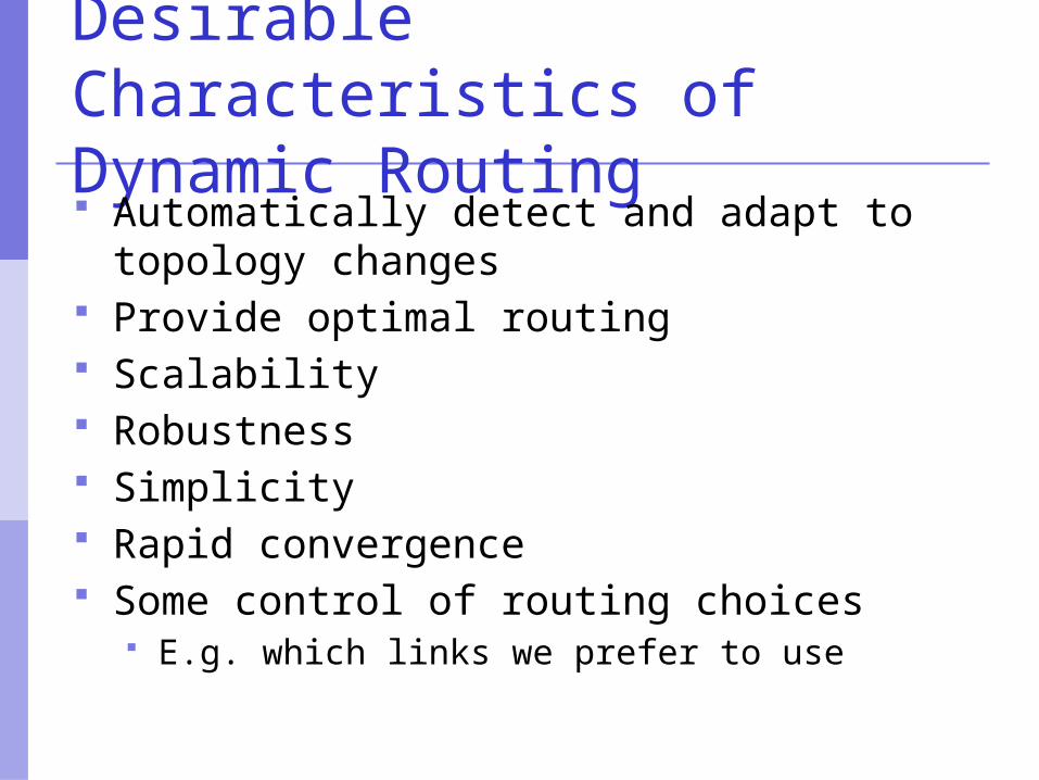
Desirable Characteristics of Dynamic Routing Automatically detect and adapt to
topology changes Provide optimal routing Scalability Robustness Simplicity Rapid convergence Some control of routing choices
E.g. which links we prefer to use
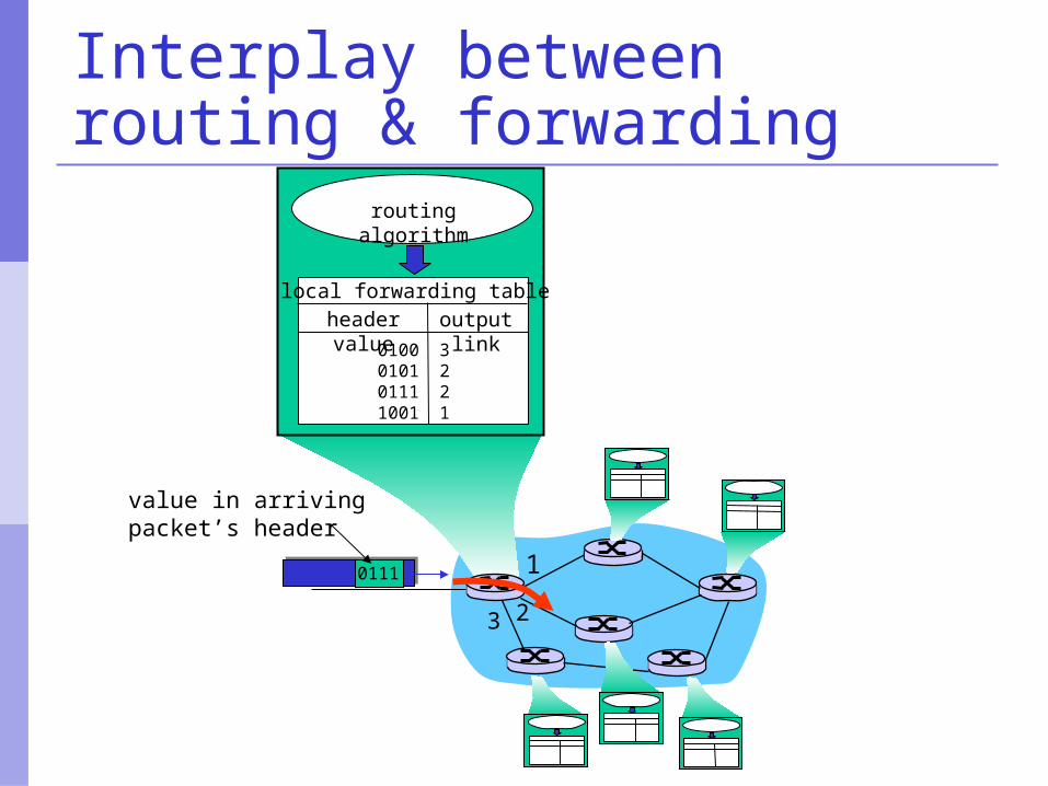
Interplay between routing & forwarding
1
23
0111
value in arrivingpacket’s header
routing algorithm
local forwarding tableheader value output link
0100010101111001
3221
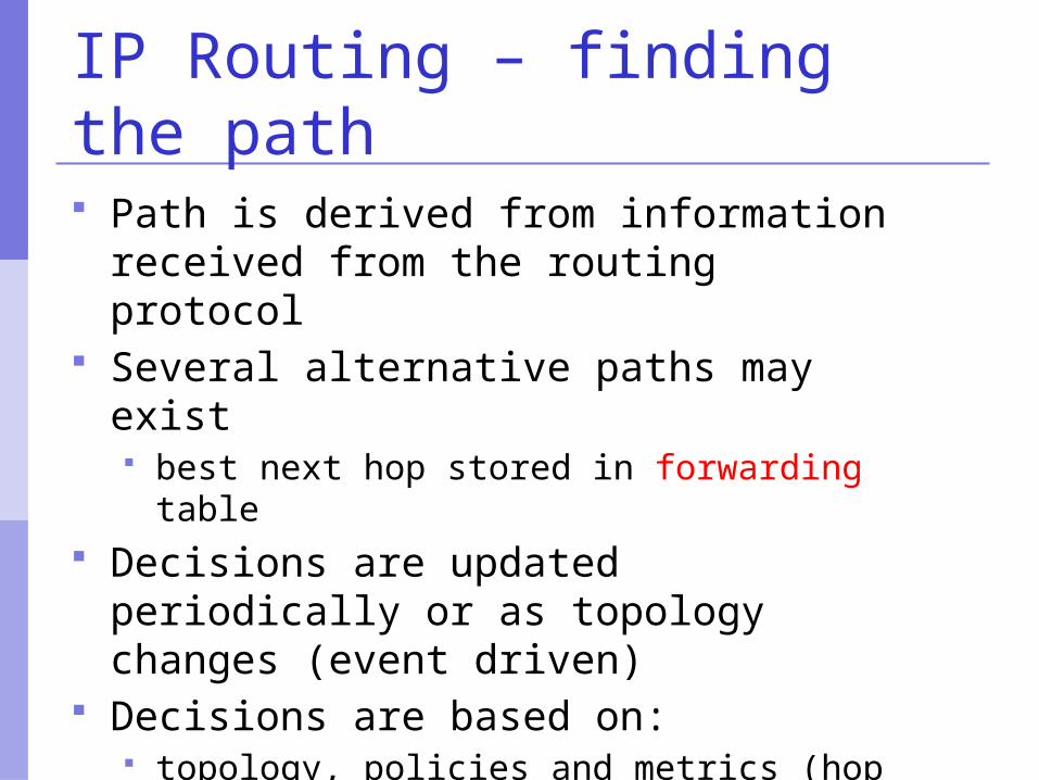
IP Routing – finding the path Path is derived from information
received from the routing protocol Several alternative paths may exist
best next hop stored in forwarding table Decisions are updated periodically or as
topology changes (event driven) Decisions are based on:
topology, policies and metrics (hop count, filtering, delay, bandwidth, etc.)
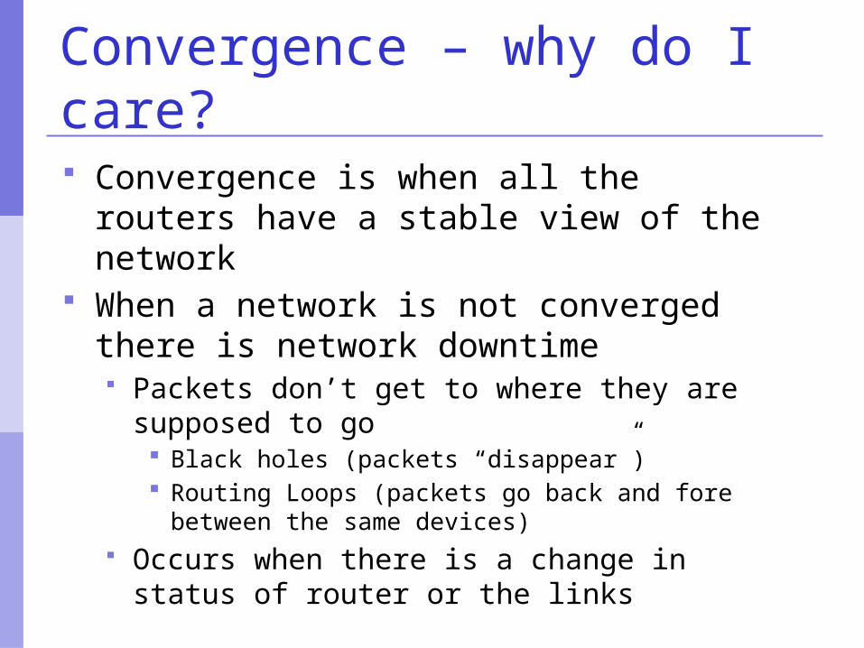
Convergence – why do I care? Convergence is when all the routers
have a stable view of the network When a network is not converged there
is network downtime Packets don’t get to where they are
supposed to go Black holes (packets “disappear”) Routing Loops (packets go back and fore between
the same devices) Occurs when there is a change in status of
router or the links
Internet Routing Hierarchy
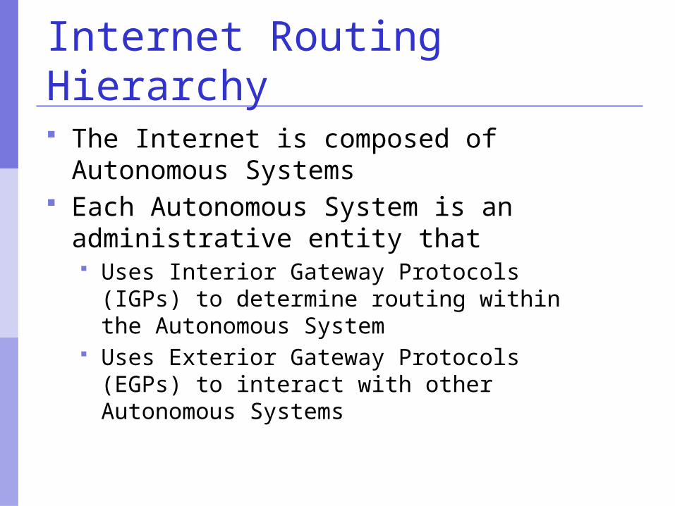
The Internet is composed of Autonomous Systems
Each Autonomous System is an administrative entity that Uses Interior Gateway Protocols (IGPs) to
determine routing within the Autonomous System
Uses Exterior Gateway Protocols (EGPs) to interact with other Autonomous Systems
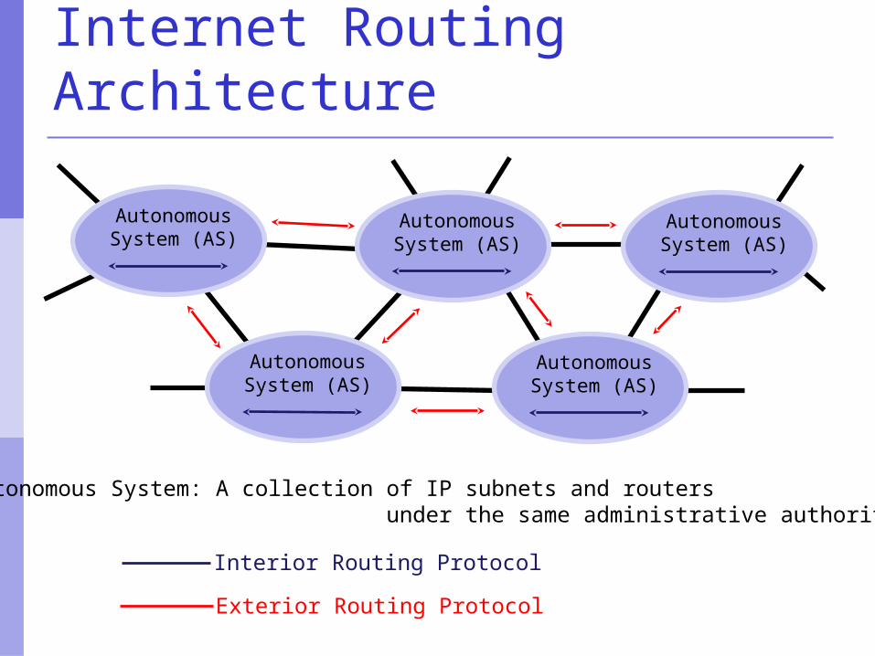
Internet Routing Architecture
AutonomousSystem (AS)
AutonomousSystem (AS)
AutonomousSystem (AS)
AutonomousSystem (AS)
AutonomousSystem (AS)
Autonomous System: A collection of IP subnets and routers under the same administrative authority.
Interior Routing Protocol
Exterior Routing Protocol
Interior Gateway Protocols
Four well known IGPs today RIP EIGRP OSPF ISIS
Exterior Gateway Protocols
One single de-facto standard: BGP
Routing’s 3 Aspects
Acquisition of information about the IP subnets that are reachable through an internet static routing configuration information dynamic routing information protocols (e.g.,
BGP4, OSPF, RIP, ISIS) each mechanism/protocol constructs a
Routing Information Base (RIB)
Routing Aspect #2
Construction of a Forwarding Table synthesis of a single table from all the
Routing Information Bases (RIBs) information about a destination subnet may
be acquired multiple ways a precedence is defined among the RIBs to
arbitrate conflicts on the same subnet Also called a Forwarding Information Base
(FIB)
Routing #3
Use of a Forwarding Table to forward individual packets selection of the next-hop router and
interface hop-by-hop, each router makes an
independent decision
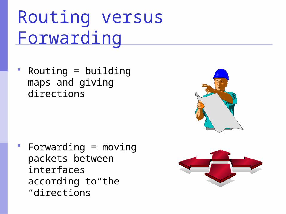
Routing versus Forwarding
Routing = building maps and giving directions
Forwarding = moving packets between interfaces according to the “directions”
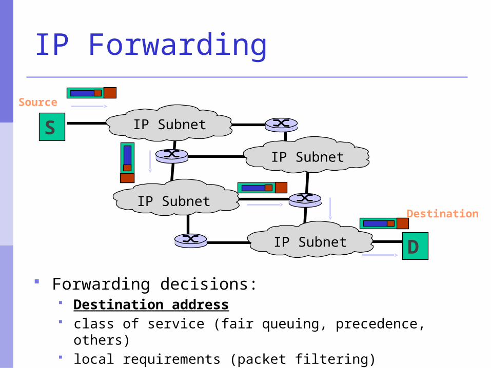
IP Forwarding
Forwarding decisions: Destination address class of service (fair queuing, precedence, others) local requirements (packet filtering)
S
D
IP Subnet
IP Subnet
IP Subnet
IP Subnet
Source
Destination
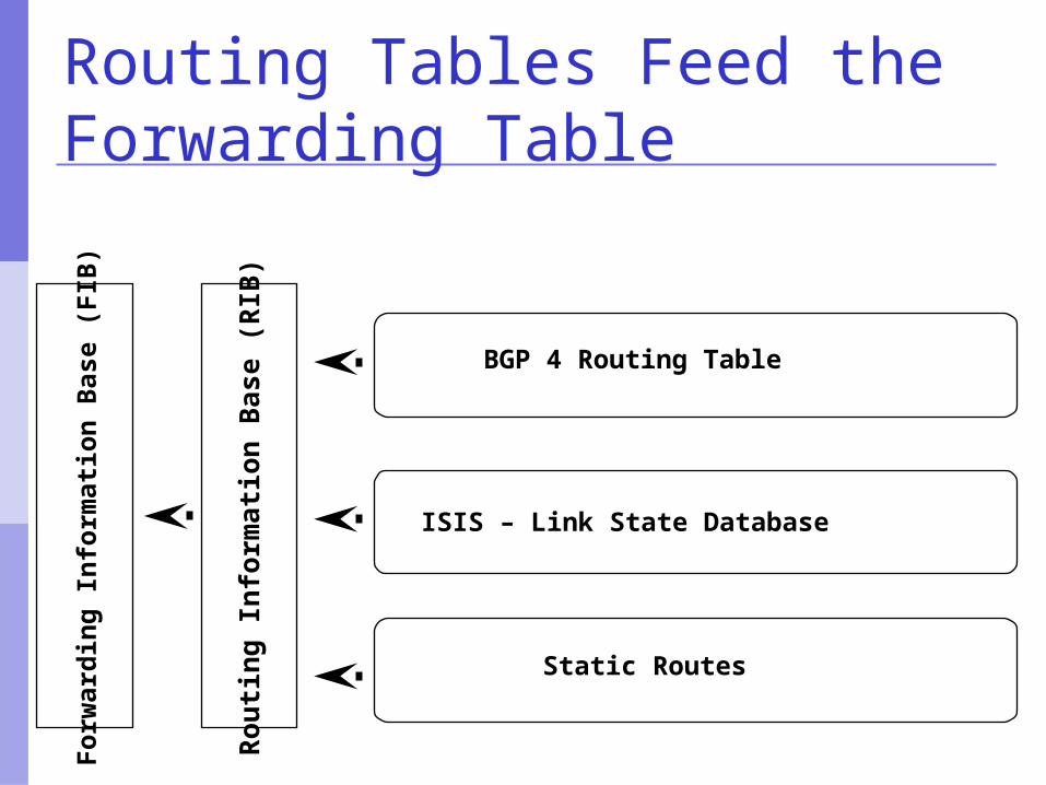
Routing Tables Feed the Forwarding Table
BGP 4 Routing Table
ISIS – Link State Database
Static Routes
Ro
uti
ng
Info
rmat
ion
Bas
e (R
IB)
Fo
rwar
din
g I
nfo
rmat
ion
Bas
e (F
IB)
RIB Construction
Each routing protocol builds its own Routing Information Base (RIB)
Each protocol has its own “view” of “costs” e.g., ISIS is administrative weights e.g., BGP4 is Autonomous System path
length
FIB Construction
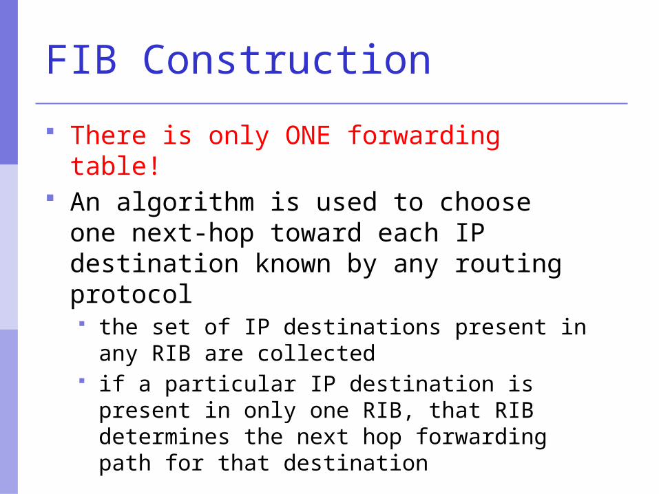
There is only ONE forwarding table! An algorithm is used to choose one
next-hop toward each IP destination known by any routing protocol the set of IP destinations present in any RIB
are collected if a particular IP destination is present in
only one RIB, that RIB determines the next hop forwarding path for that destination
FIB Construction
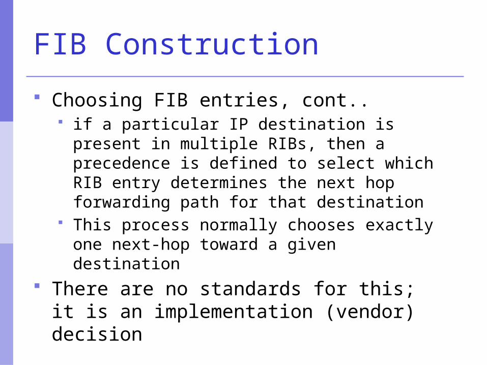
Choosing FIB entries, cont.. if a particular IP destination is present in
multiple RIBs, then a precedence is defined to select which RIB entry determines the next hop forwarding path for that destination
This process normally chooses exactly one next-hop toward a given destination
There are no standards for this; it is an implementation (vendor) decision
FIB Contents
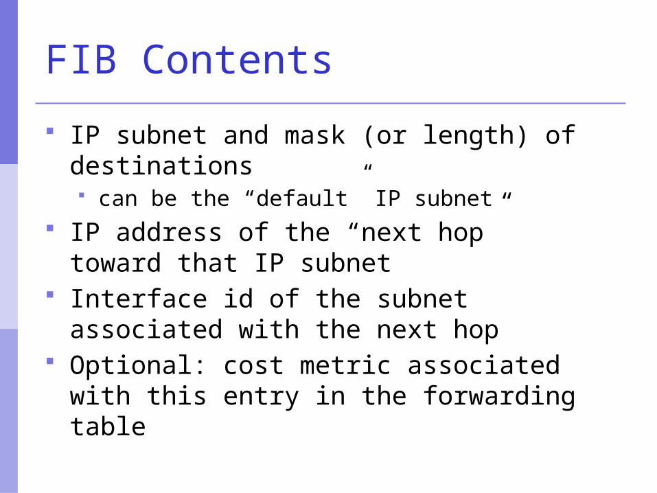
IP subnet and mask (or length) of destinations can be the “default” IP subnet
IP address of the “next hop” toward that IP subnet
Interface id of the subnet associated with the next hop
Optional: cost metric associated with this entry in the forwarding table

IP routing
Default route where to send packets if there is no entry
for the destination in the routing table most machines have a single default route often referred to as a default gateway
0.0.0.0/0 matches all possible destinations, but is usually
not the longest match
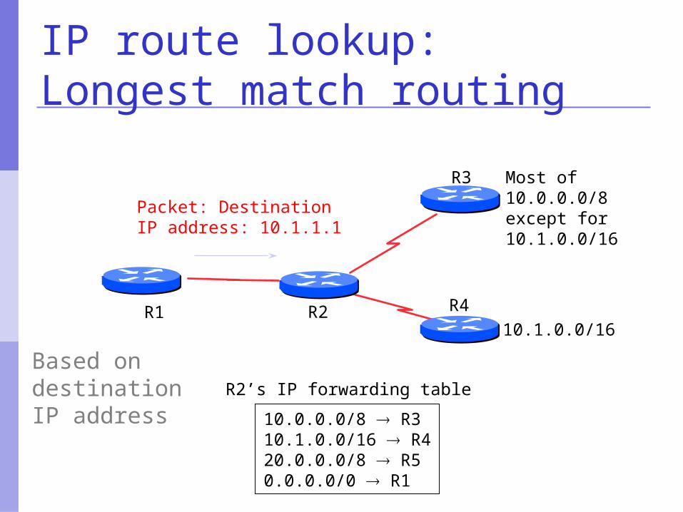
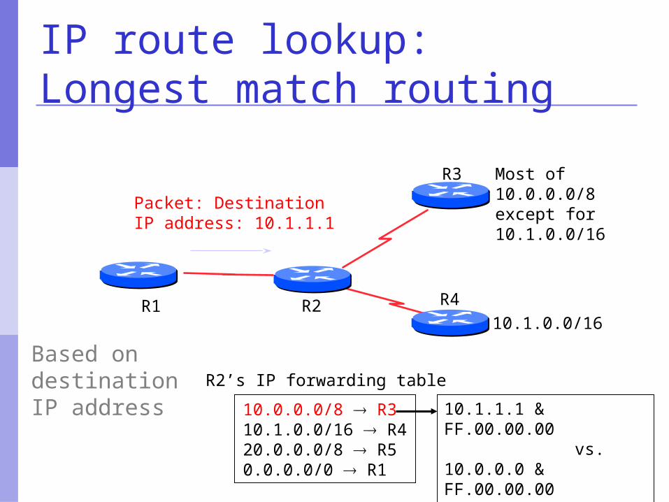
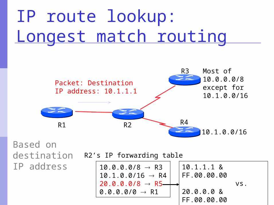
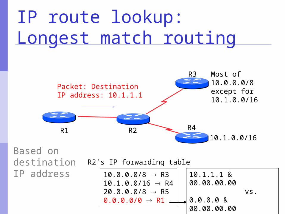
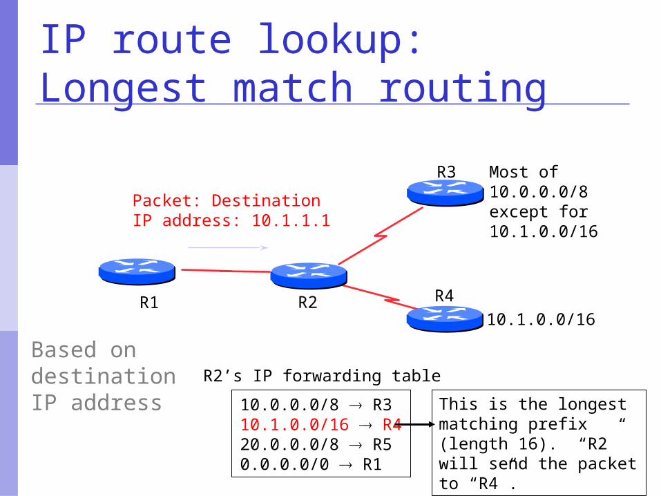
10.0.0.0/8 R310.1.0.0/16 R420.0.0.0/8 R50.0.0.0/0 R1
R2’s IP forwarding table
IP route lookup:Longest match routing
R2
R3
R4
Most of 10.0.0.0/8 except for10.1.0.0/16
10.1.0.0/16
Based on destination IP address
Packet: DestinationIP address: 10.1.1.1
R1
10.0.0.0/8 R310.1.0.0/16 R420.0.0.0/8 R50.0.0.0/0 R1
R2’s IP forwarding table
IP route lookup:Longest match routing
R2
R3
R4
Most of 10.0.0.0/8 except for10.1.0.0/16
10.1.0.0/16
Based on destination IP address
Packet: DestinationIP address: 10.1.1.1
10.1.1.1 & FF.00.00.00 vs.10.0.0.0 & FF.00.00.00Match! (length 8)
R1

10.0.0.0/8 R310.1.0.0/16 R420.0.0.0/8 R50.0.0.0/0 R1
R2’s IP forwarding table
IP route lookup:Longest match routing
R2
R3
R4
Most of 10.0.0.0/8 except for10.1.0.0/16
10.1.0.0/16
Based on destination IP address
Packet: DestinationIP address: 10.1.1.1
10.1.1.1 & FF.FF.00.00 vs.10.1.0.0 & FF.FF.00.00Match! (length 16)
R1
10.0.0.0/8 R310.1.0.0/16 R420.0.0.0/8 R50.0.0.0/0 R1
R2’s IP forwarding table
IP route lookup:Longest match routing
R2
R3
R410.1.0.0/16
Based on destination IP address
Packet: DestinationIP address: 10.1.1.1
10.1.1.1 & FF.00.00.00 vs.20.0.0.0 & FF.00.00.00No Match!
R1
Most of 10.0.0.0/8 except for10.1.0.0/16
10.0.0.0/8 R310.1.0.0/16 R420.0.0.0/8 R50.0.0.0/0 R1
R2’s IP forwarding table
IP route lookup:Longest match routing
R2
R3
R410.1.0.0/16
Based on destination IP address
Packet: DestinationIP address: 10.1.1.1
10.1.1.1 & 00.00.00.00 vs.0.0.0.0 & 00.00.00.00Match! (length 0)
R1
Most of 10.0.0.0/8 except for10.1.0.0/16
10.0.0.0/8 R310.1.0.0/16 R420.0.0.0/8 R50.0.0.0/0 R1
R2’s IP forwarding table
IP route lookup:Longest match routing
R3
R4
Most of 10.0.0.0/8 except for10.1.0.0/16
10.1.0.0/16
Based on destination IP address
Packet: DestinationIP address: 10.1.1.1
This is the longest matching prefix (length 16). “R2” will send the packet to “R4”.
R2R1
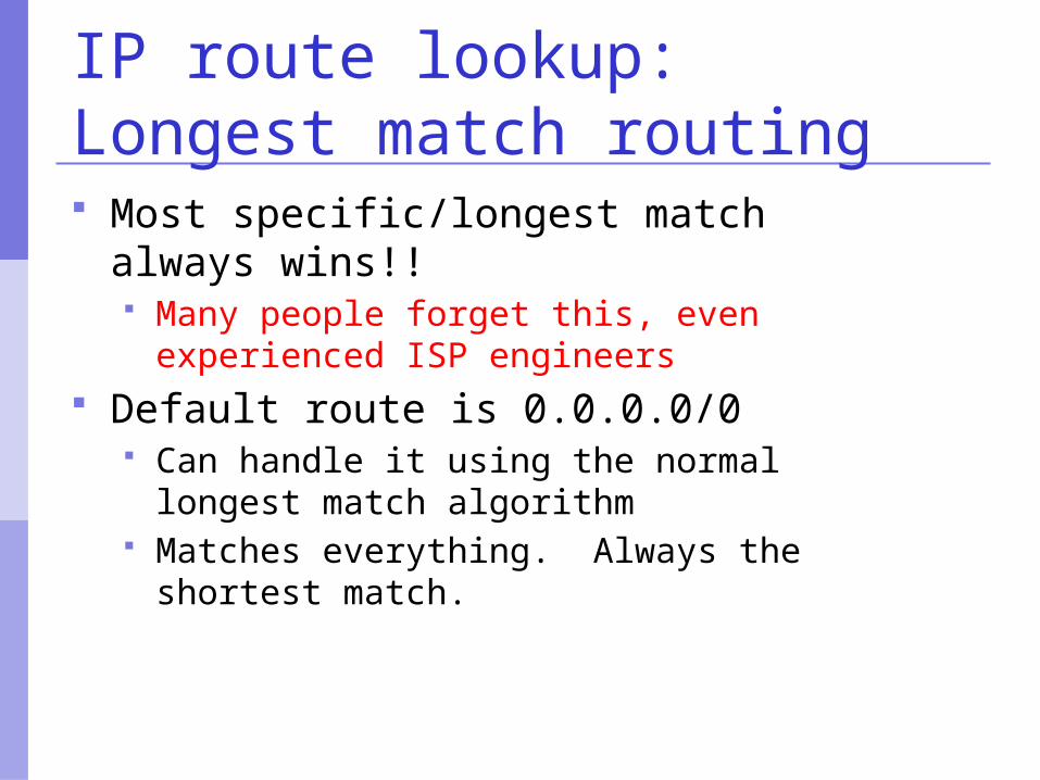
IP route lookup:Longest match routing Most specific/longest match always
wins!! Many people forget this, even experienced
ISP engineers Default route is 0.0.0.0/0
Can handle it using the normal longest match algorithm
Matches everything. Always the shortest match.
u
yx
wv
z2
2
13
1
1
2
53
5
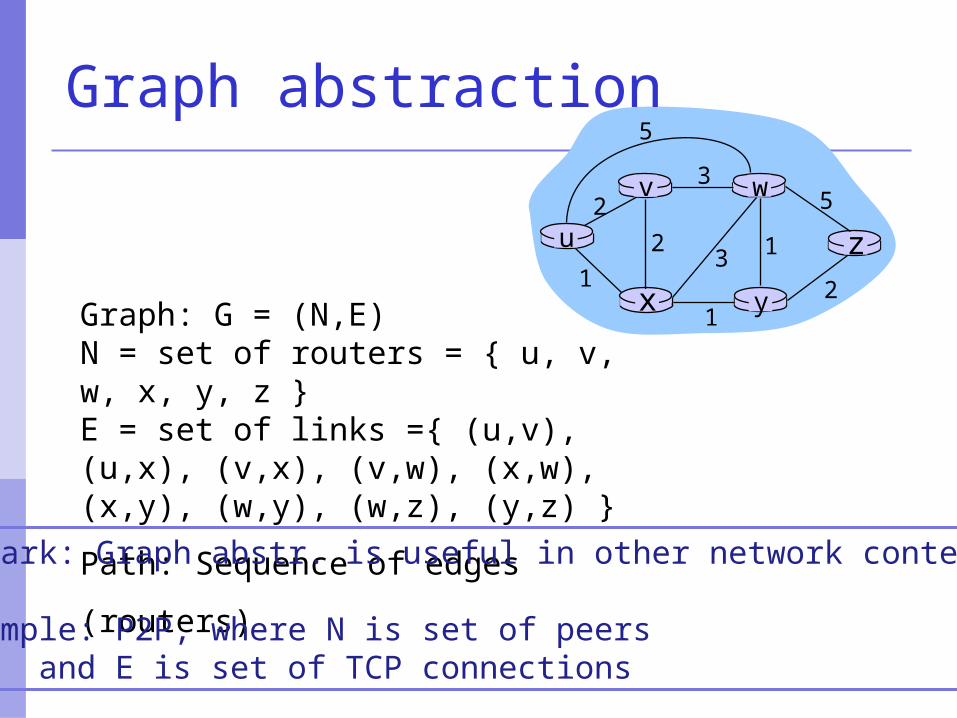
Graph: G = (N,E)N = set of routers = { u, v, w, x, y, z }E = set of links ={ (u,v), (u,x), (v,x), (v,w), (x,w), (x,y), (w,y), (w,z), (y,z) }
Path: Sequence of edges (routers)
Graph abstraction
Remark: Graph abstr. is useful in other network contexts
Example: P2P, where N is set of peers and E is set of TCP connections
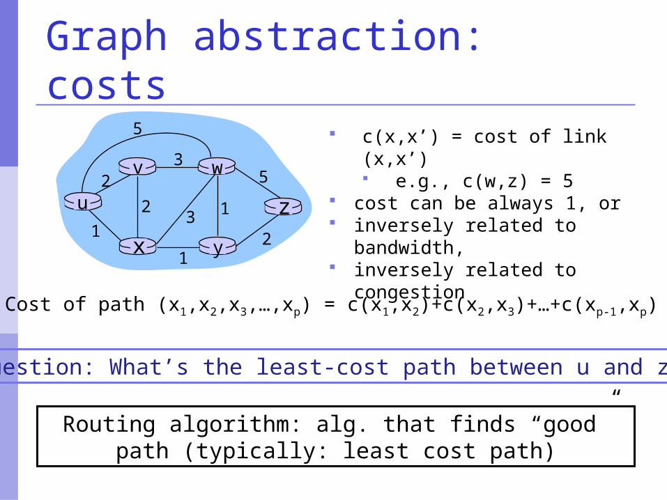
Graph abstraction: costs
c(x,x’) = cost of link (x,x’) e.g., c(w,z) = 5
cost can be always 1, or inversely related to bandwidth, inversely related to congestion
u
yx
wv
z2
2
13
1
1
2
53
5
Cost of path (x1,x2,x3,…,xp) = c(x1,x2)+c(x2,x3)+…+c(xp-1,xp)
Question: What’s the least-cost path between u and z ?
Routing algorithm: alg. that finds “good” path (typically: least cost path)
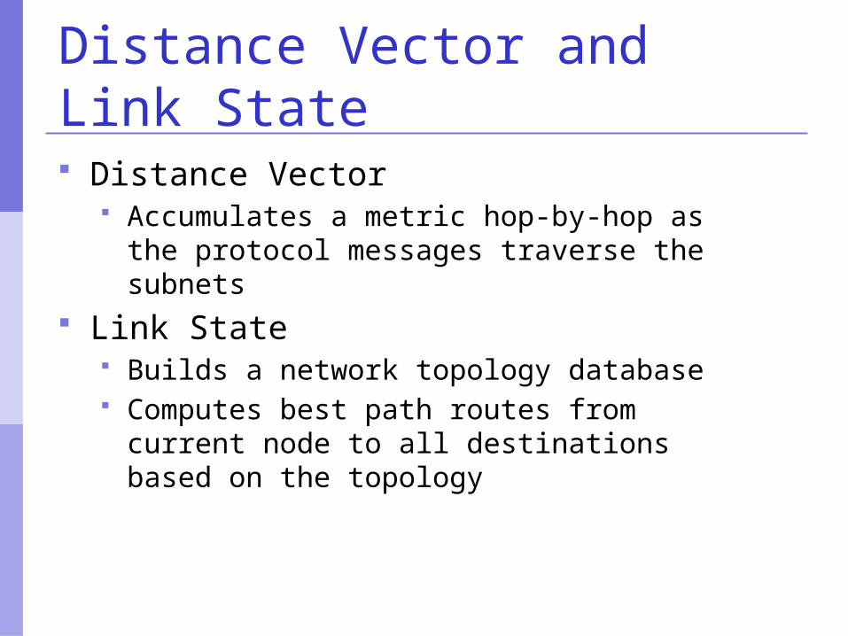
Distance Vector and Link State Distance Vector
Accumulates a metric hop-by-hop as the protocol messages traverse the subnets
Link State Builds a network topology database Computes best path routes from current
node to all destinations based on the topology
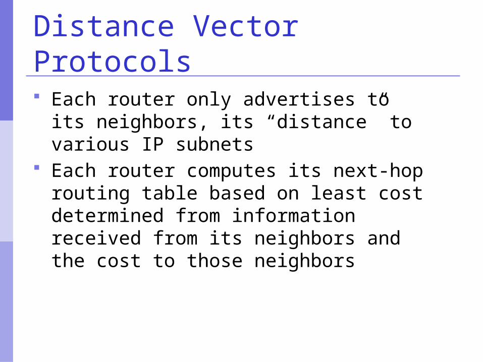
Distance Vector Protocols
Each router only advertises to its neighbors, its “distance” to various IP subnets
Each router computes its next-hop routing table based on least cost determined from information received from its neighbors and the cost to those neighbors
Distance Vector Algorithm
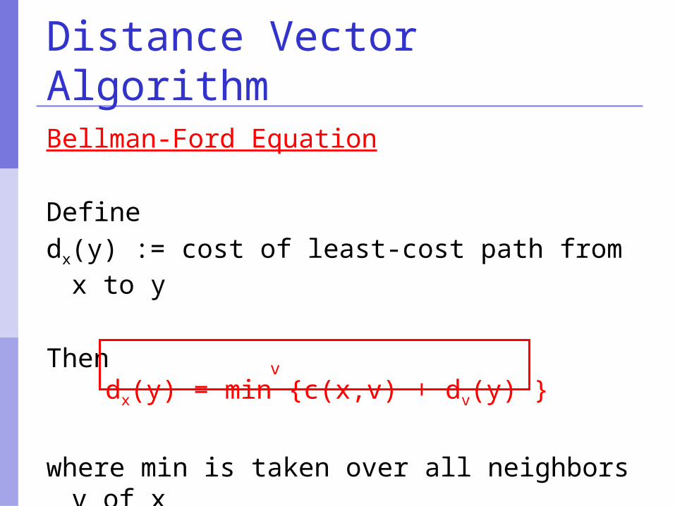
Bellman-Ford Equation
Definedx(y) := cost of least-cost path from x to y
Thendx(y) = min {c(x,v) + dv(y) }
where min is taken over all neighbors v of x
v
Bellman-Ford example
u
yx
wv
z2
2
13
1
1
2
53
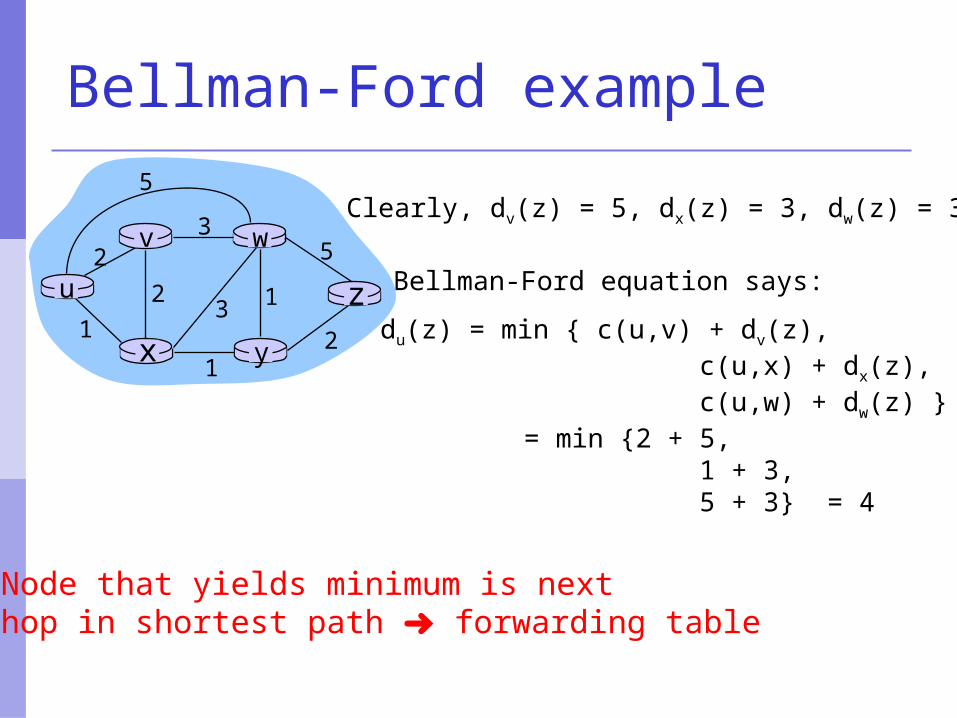
5Clearly, dv(z) = 5, dx(z) = 3, dw(z) = 3
du(z) = min { c(u,v) + dv(z), c(u,x) + dx(z), c(u,w) + dw(z) } = min {2 + 5, 1 + 3, 5 + 3} = 4
Node that yields minimum is nexthop in shortest path ➜ forwarding table
Bellman-Ford equation says:
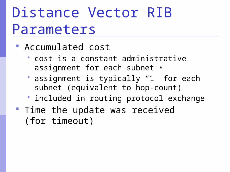
Distance Vector RIB Parameters Accumulated cost
cost is a constant administrative assignment for each subnet
assignment is typically “1” for each subnet (equivalent to hop-count)
included in routing protocol exchange Time the update was received
(for timeout)
Distance Vector RIB Parameters The next-hop the entry was received
from sender’s id is included in routing protocol
exchange Accumulated Hop count and Maximum
Hop Count used to detect cycles hop count included in routing protocol
exchange
Distance Vector: Additions
When a router learns of new reachable subnets at router startup when an interface in enabled or restored to
service A routing update is broadcast to all
neighbors
Distance Vector: Additions
Any router receiving the packet compares the cost it received in the new packet with that in its RIB
If the cost is smaller or the subnet is new the new entry is used in the RIB the new entry is broadcast to all its
neighbors (except the one from which it was received)
Distance Vector: Removals
Each RIB entry is aged a timeout defines when an entry is removed
from the RIB Periodically, each router re-advertises
all the routes it knows to its neighbors this can be done in many ways: from simple
neighbor hellos to enumeration of all routes
Distance Vector: Removals
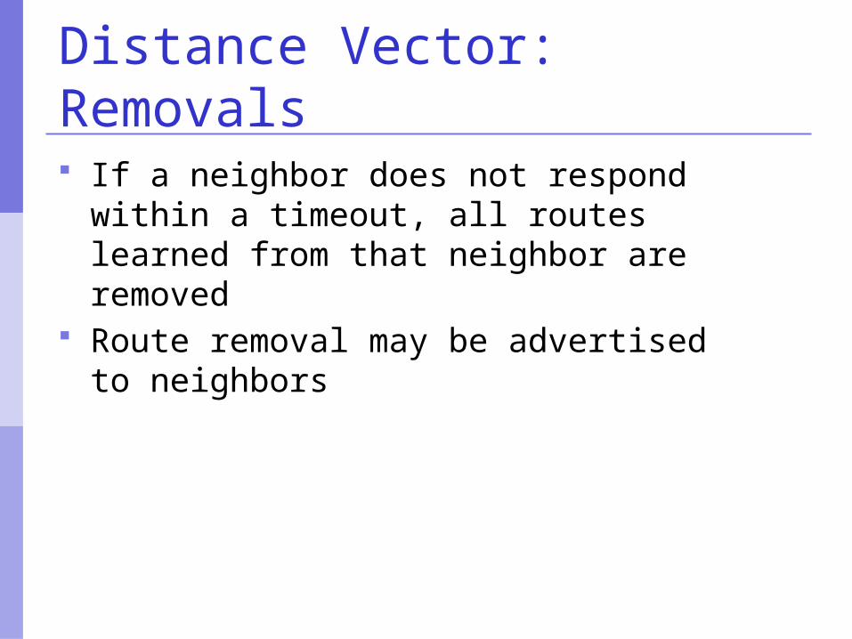
If a neighbor does not respond within a timeout, all routes learned from that neighbor are removed
Route removal may be advertised to neighbors
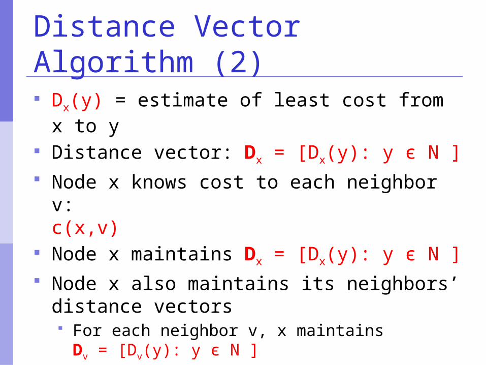
Distance Vector Algorithm (2) Dx(y) = estimate of least cost from x to y Distance vector: Dx = [Dx(y): y є N ] Node x knows cost to each neighbor v:
c(x,v) Node x maintains Dx = [Dx(y): y є N ] Node x also maintains its neighbors’
distance vectors For each neighbor v, x maintains
Dv = [Dv(y): y є N ]
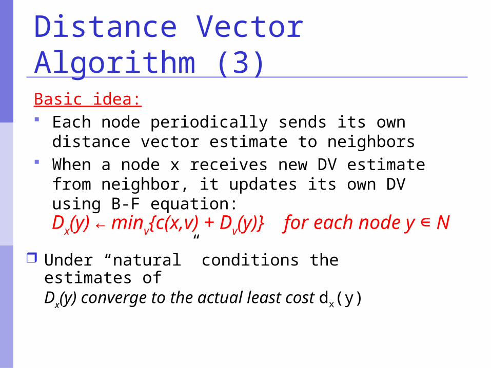
Distance Vector Algorithm (3)Basic idea: Each node periodically sends its own distance
vector estimate to neighbors When a node x receives new DV estimate from
neighbor, it updates its own DV using B-F equation:Dx(y) ← minv{c(x,v) + Dv(y)} for each node y ∊ N
Under “natural” conditions the estimates of Dx(y) converge to the actual least cost dx(y)
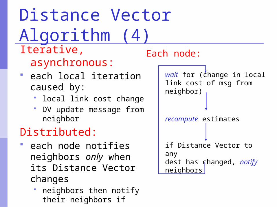
Distance Vector Algorithm (4)Iterative,
asynchronous: each local iteration
caused by: local link cost change DV update message from
neighbor
Distributed: each node notifies
neighbors only when its Distance Vector changes neighbors then notify their
neighbors if necessary
wait for (change in local link cost of msg from neighbor)
recompute estimates
if Distance Vector to any dest has changed, notify neighbors
Each node:
cost tox y z
xyz
0 2 7
from
2 0 13 1 0
x y z
xyz
0 2 3
from
cost to
2 0 17 1 0
x y z
xyz
0 2 7
from
cost to
2 0 17 1 0
cost tox y z
xyz
0 2 3fr
om
3 1 0
2 0 1
x y z
xyz
0 2 3
from
cost to
2 0 13 1 0
x y z
xyz
0 2 3
from
cost to
2 0 13 1 0
time
x z12
7
y
x y z
xyz
0 2 7
∞ ∞ ∞∞ ∞ ∞
from
cost tonode x table
∞ ∞
from
x y z
xyz ∞ ∞ ∞
cost to
∞2 0 1
node y table
from
x y z
xyz
∞ ∞ ∞7 1 0
cost to
∞ ∞ ∞
node z table
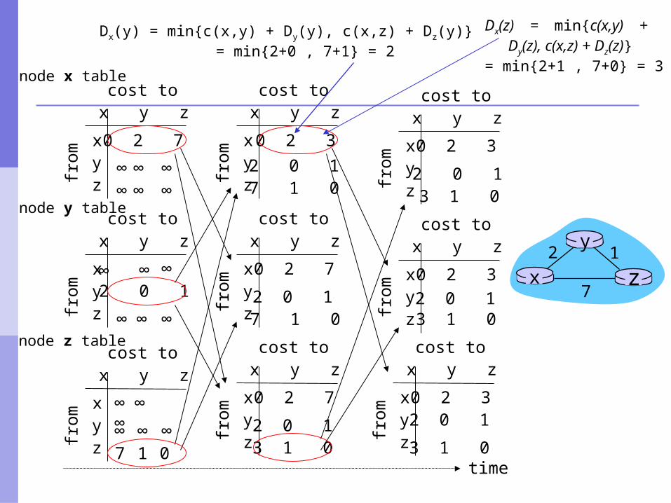
Dx(y) = min{c(x,y) + Dy(y), c(x,z) + Dz(y)} = min{2+0 , 7+1} = 2
Dx(z) = min{c(x,y) + Dy(z), c(x,z) + Dz(z)} = min{2+1 , 7+0} = 3
Distance Vector (DV): link cost changes
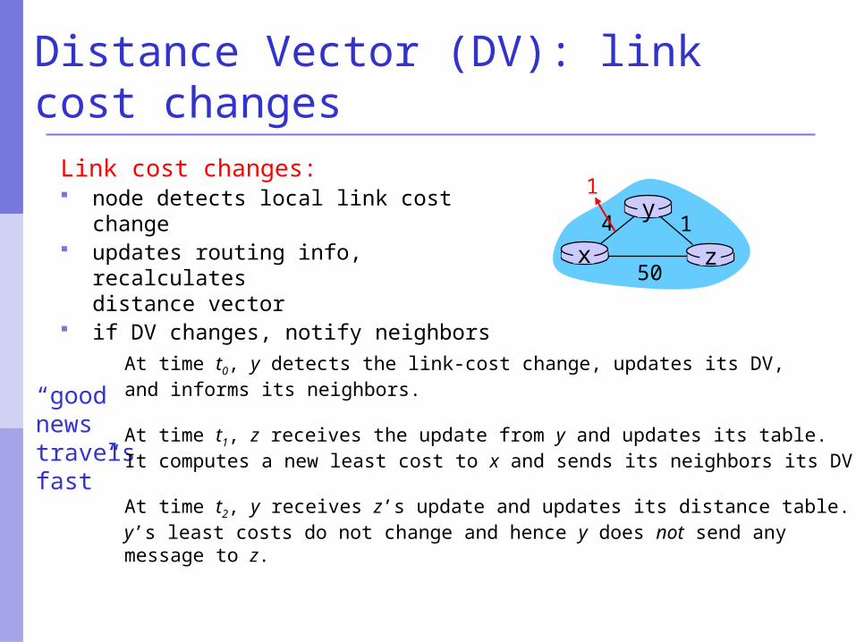
Link cost changes: node detects local link cost change updates routing info, recalculates
distance vector if DV changes, notify neighbors
“goodnews travelsfast”
x z14
50
y1
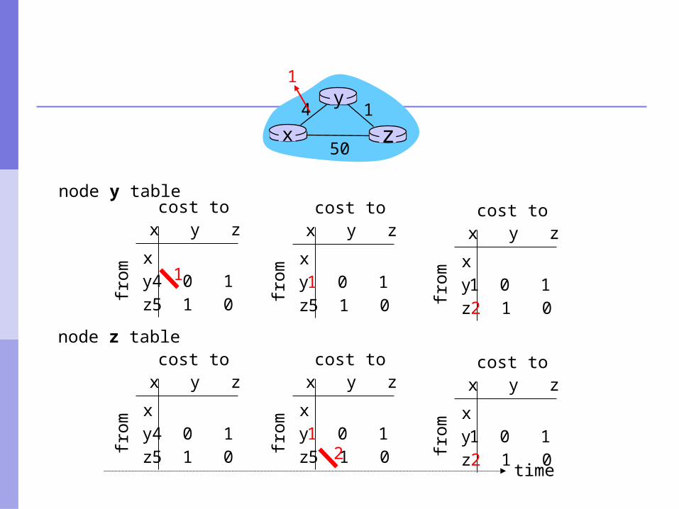
At time t0, y detects the link-cost change, updates its DV, and informs its neighbors.
At time t1, z receives the update from y and updates its table. It computes a new least cost to x and sends its neighbors its DV.
At time t2, y receives z’s update and updates its distance table. y’s least costs do not change and hence y does not send any message to z.
x y z
x
from
cost to
y 4 0 1z 5 1 0
time
node y table
node z table
x z14
50
y1
x y z
x
from
cost to
y 4 0 1z 5 1 0
x y z
xfr
om
cost to
y 1 0 1z 5 1 0
1
x y z
x
from
cost to
y 1 0 1z 5 1 02
x y z
x
from
cost to
y 1 0 1z 2 1 0
x y z
x
from
cost to
y 1 0 1z 2 1 0
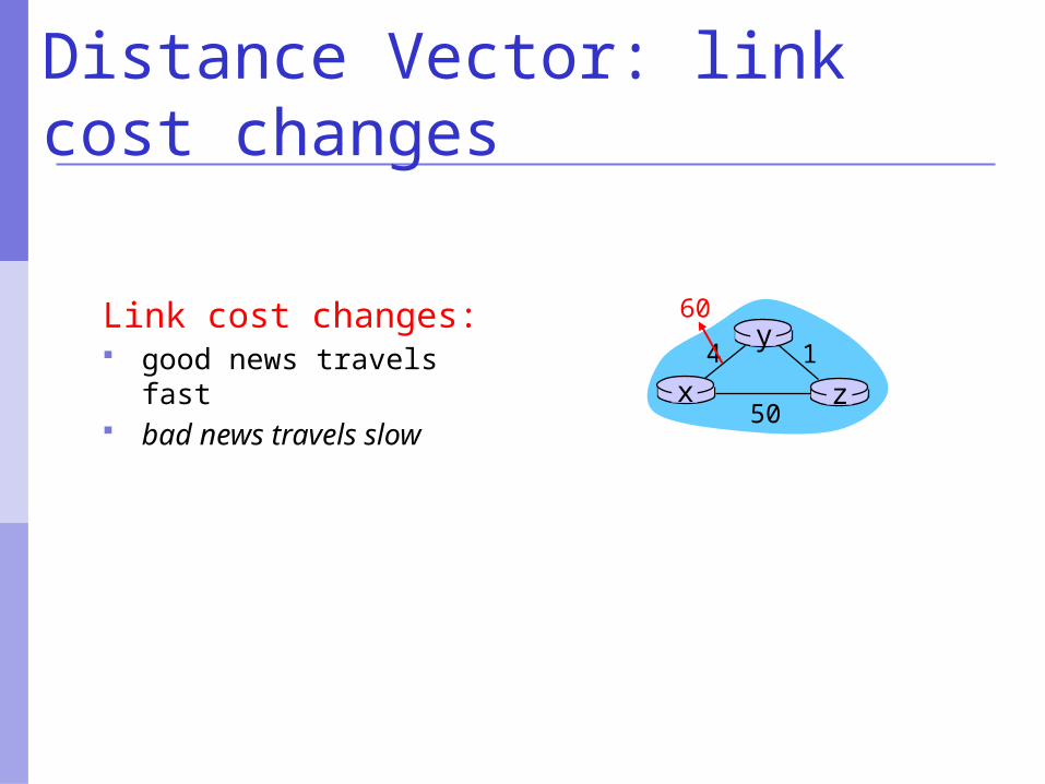
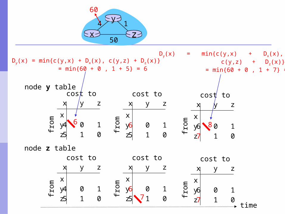
Distance Vector: link cost changes
Link cost changes: good news travels fast bad news travels slow x z
14
50
y60
x y z
x
from
cost to
y 4 0 1z 5 1 0
time
node y table
node z table
x z14
50
y60
x y z
x
from
cost to
y 4 0 1z 5 1 0
x y z
xfr
om
cost to
y 6 0 1z 5 1 0
6
x y z
x
from
cost to
y 6 0 1z 5 1 07
x y z
x
from
cost to
y 6 0 1z 7 1 0
x y z
xfr
om
cost to
y 6 0 1z 7 1 0
Dy(x) = min{c(y,x) + Dx(x), c(y,z) + Dz(x)} = min{60 + 0 , 1 + 5} = 6
8
Dy(x) = min{c(y,x) + Dx(x), c(y,z) + Dz(x)}
= min{60 + 0 , 1 + 7} = 8
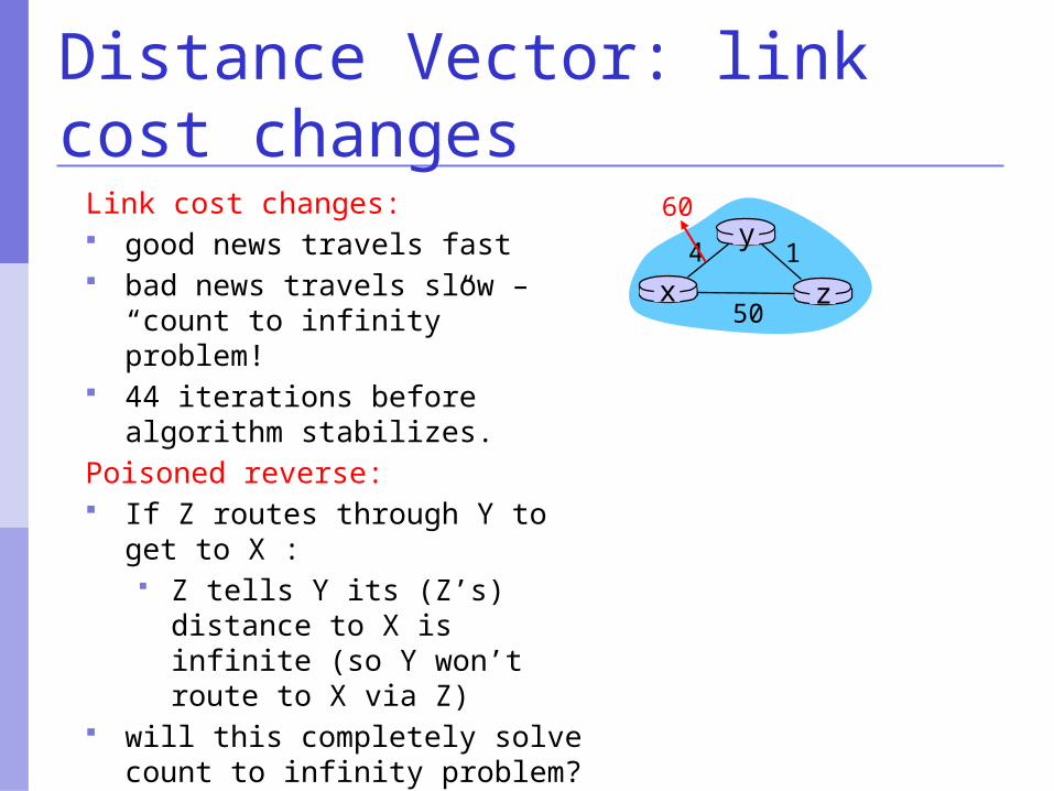
Distance Vector: link cost changes
Link cost changes: good news travels fast bad news travels slow –
“count to infinity” problem! 44 iterations before algorithm
stabilizes.Poisoned reverse: If Z routes through Y to get to
X : Z tells Y its (Z’s) distance to
X is infinite (so Y won’t route to X via Z)
will this completely solve count to infinity problem?
x z14
50
y60
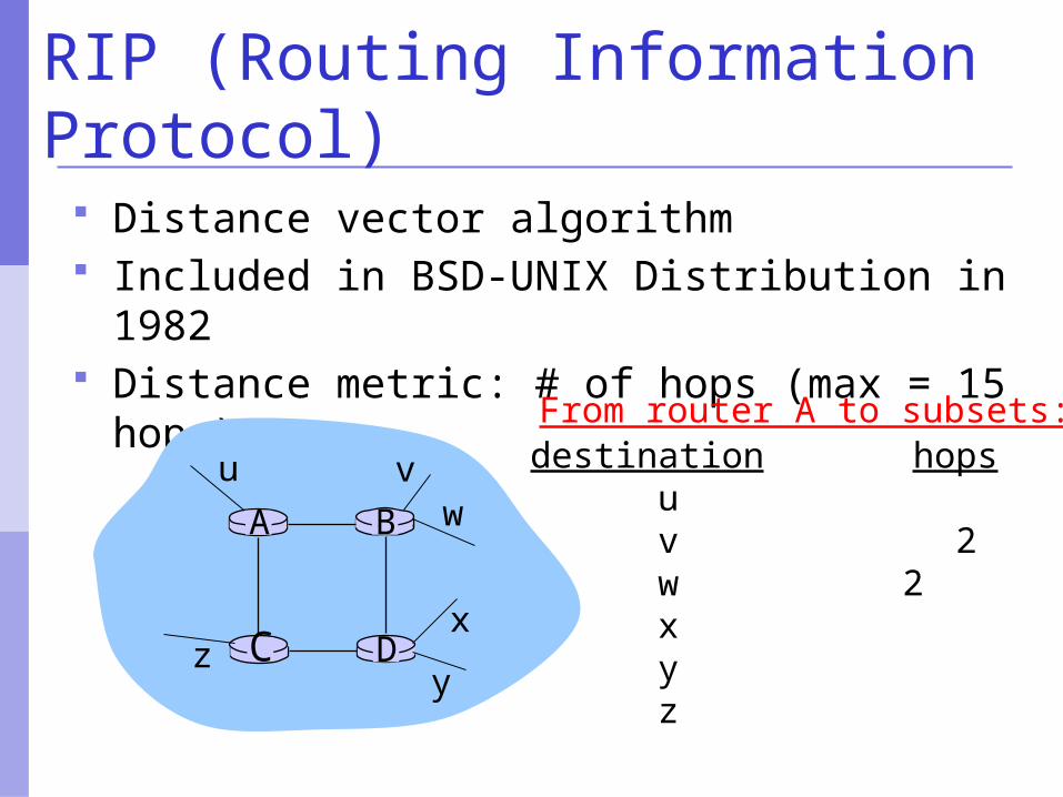
RIP (Routing Information Protocol)
Distance vector algorithm Included in BSD-UNIX Distribution in 1982 Distance metric: # of hops (max = 15
hops)
DC
BA
u vw
x
yz
destination hops u 1 v 2 w 2 x 3 y 3 z 2
From router A to subsets:
RIP advertisements
Distance vectors: exchanged among neighbors every 30 sec via Response Message (also called advertisement)
Each advertisement: list of up to 25 destination nets within AS
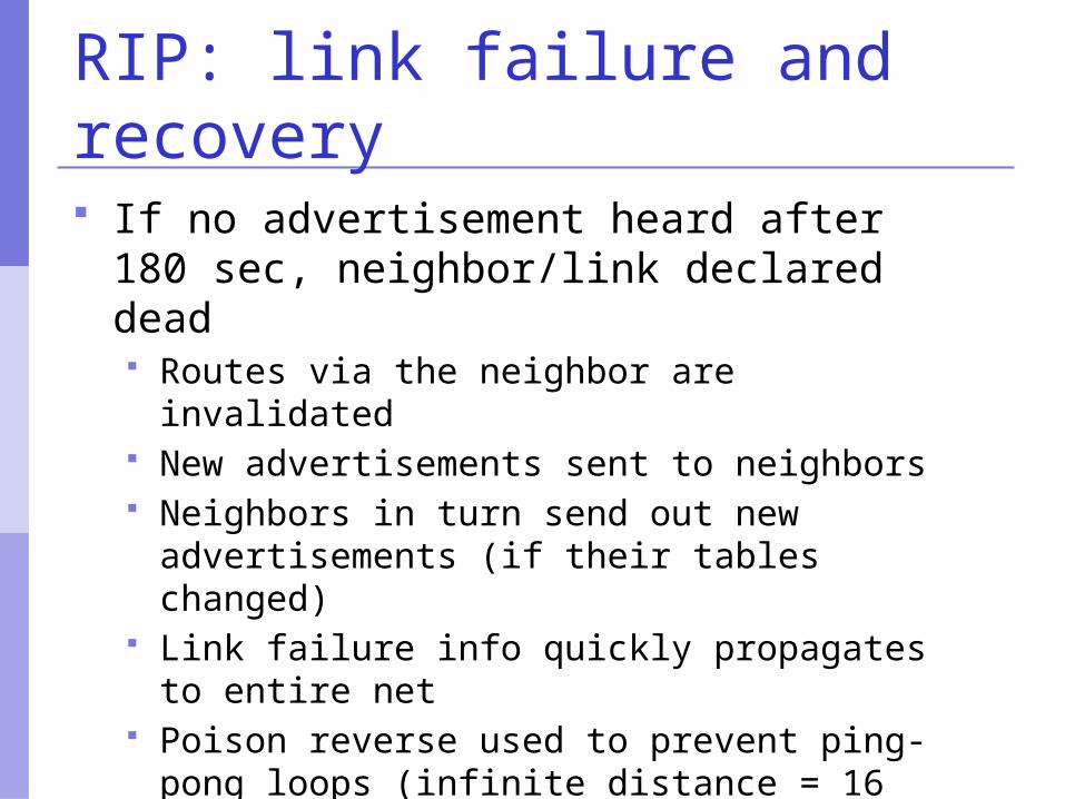
RIP: link failure and recovery If no advertisement heard after 180 sec,
neighbor/link declared dead Routes via the neighbor are invalidated New advertisements sent to neighbors Neighbors in turn send out new
advertisements (if their tables changed) Link failure info quickly propagates to entire
net Poison reverse used to prevent ping-pong
loops (infinite distance = 16 hops)
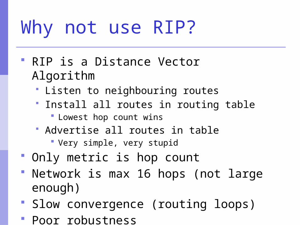
Why not use RIP?
RIP is a Distance Vector Algorithm Listen to neighbouring routes Install all routes in routing table
Lowest hop count wins Advertise all routes in table
Very simple, very stupid
Only metric is hop count Network is max 16 hops (not large
enough) Slow convergence (routing loops) Poor robustness
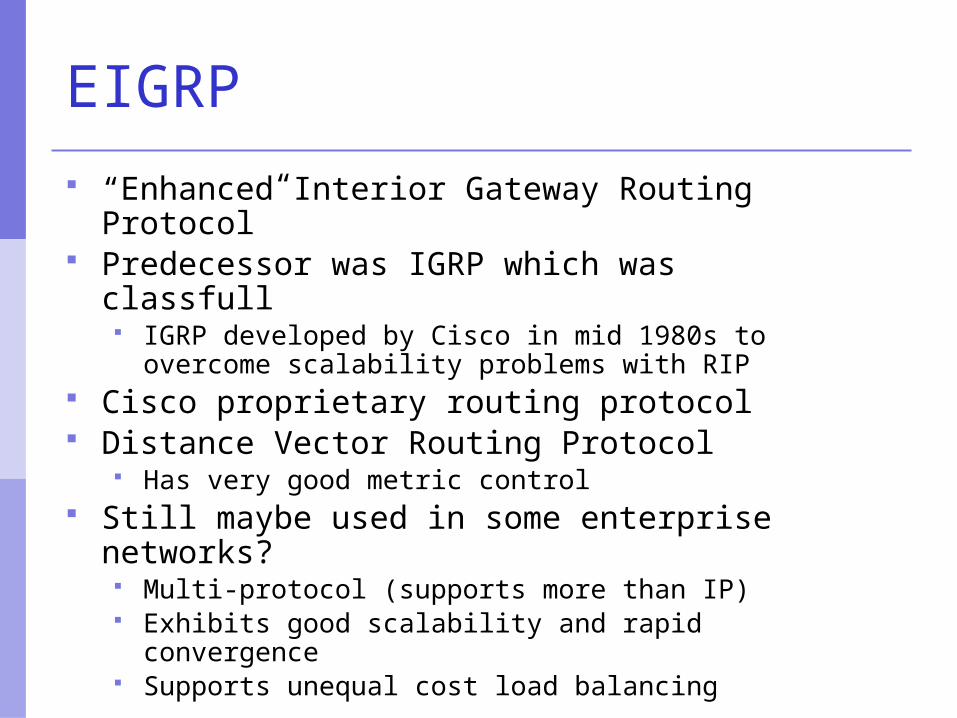
EIGRP
“Enhanced Interior Gateway Routing Protocol” Predecessor was IGRP which was classfull
IGRP developed by Cisco in mid 1980s to overcome scalability problems with RIP
Cisco proprietary routing protocol Distance Vector Routing Protocol
Has very good metric control Still maybe used in some enterprise networks?
Multi-protocol (supports more than IP) Exhibits good scalability and rapid convergence Supports unequal cost load balancing
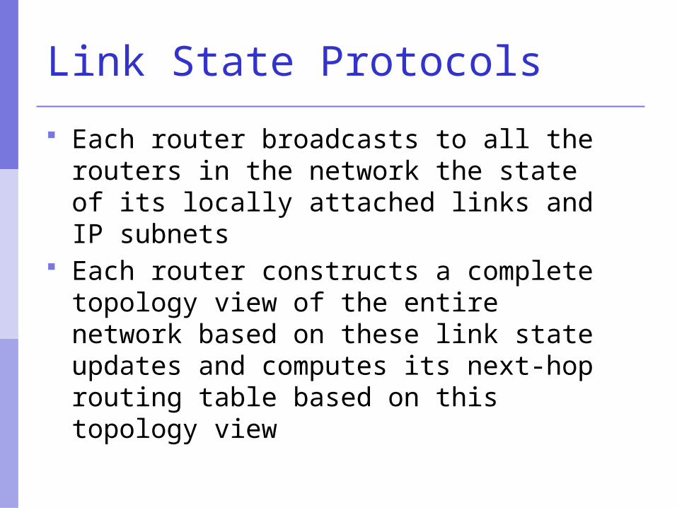
Link State Protocols
Each router broadcasts to all the routers in the network the state of its locally attached links and IP subnets
Each router constructs a complete topology view of the entire network based on these link state updates and computes its next-hop routing table based on this topology view
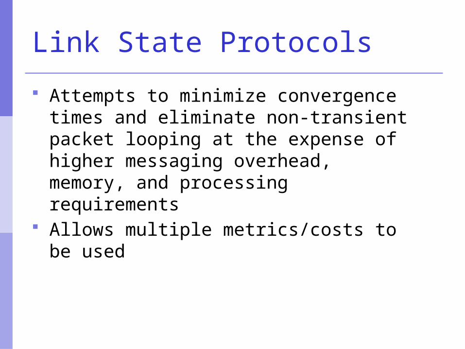
Link State Protocols
Attempts to minimize convergence times and eliminate non-transient packet looping at the expense of higher messaging overhead, memory, and processing requirements
Allows multiple metrics/costs to be used
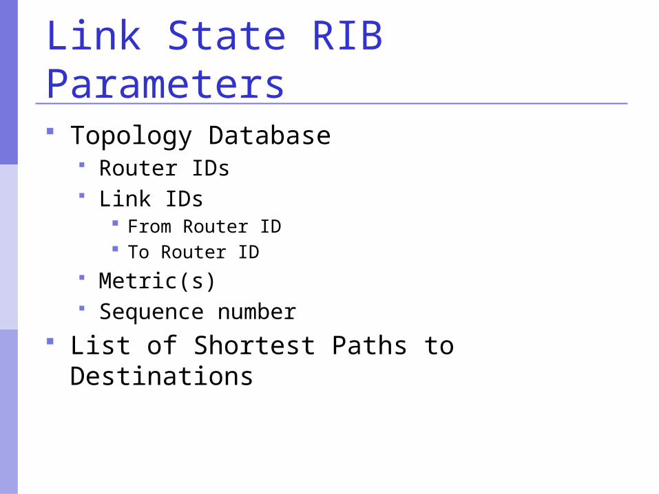
Link State RIB Parameters
Topology Database Router IDs Link IDs
From Router ID To Router ID
Metric(s) Sequence number
List of Shortest Paths to Destinations
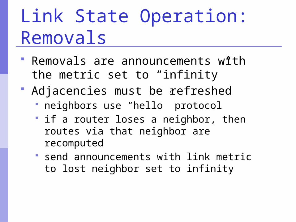
Link State Operation: Removals Removals are announcements with the
metric set to “infinity” Adjacencies must be refreshed
neighbors use “hello” protocol if a router loses a neighbor, then routes via
that neighbor are recomputed send announcements with link metric to lost
neighbor set to infinity
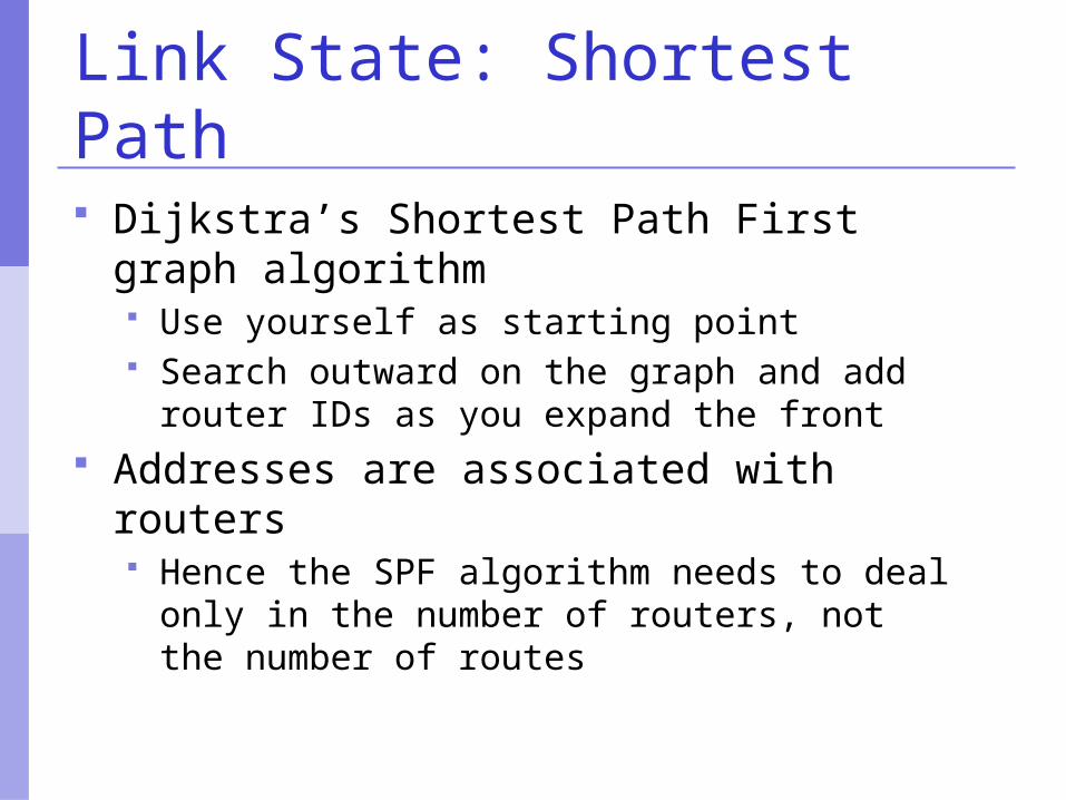
Link State: Shortest Path
Dijkstra’s Shortest Path First graph algorithm Use yourself as starting point Search outward on the graph and add router
IDs as you expand the front Addresses are associated with routers
Hence the SPF algorithm needs to deal only in the number of routers, not the number of routes
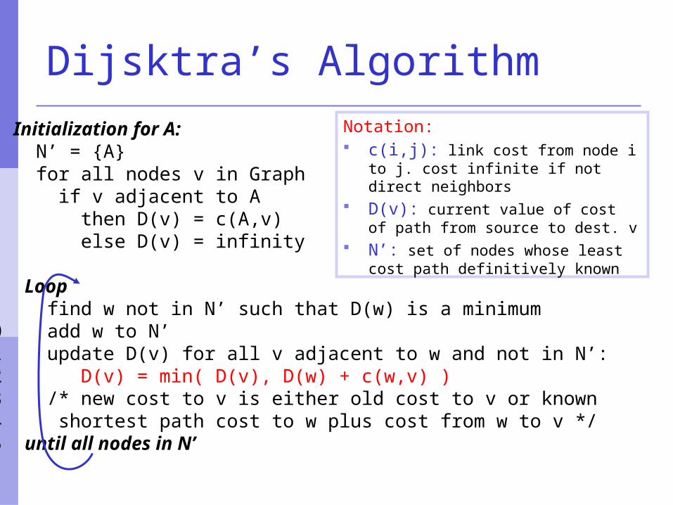
Dijsktra’s Algorithm
1 Initialization for A: 2 N’ = {A} 3 for all nodes v in Graph4 if v adjacent to A 5 then D(v) = c(A,v) 6 else D(v) = infinity 7 8 Loop 9 find w not in N’ such that D(w) is a minimum 10 add w to N’ 11 update D(v) for all v adjacent to w and not in N’: 12 D(v) = min( D(v), D(w) + c(w,v) ) 13 /* new cost to v is either old cost to v or known 14 shortest path cost to w plus cost from w to v */ 15 until all nodes in N’
Notation: c(i,j): link cost from node i to j. cost
infinite if not direct neighbors D(v): current value of cost of path
from source to dest. v N’: set of nodes whose least cost
path definitively known
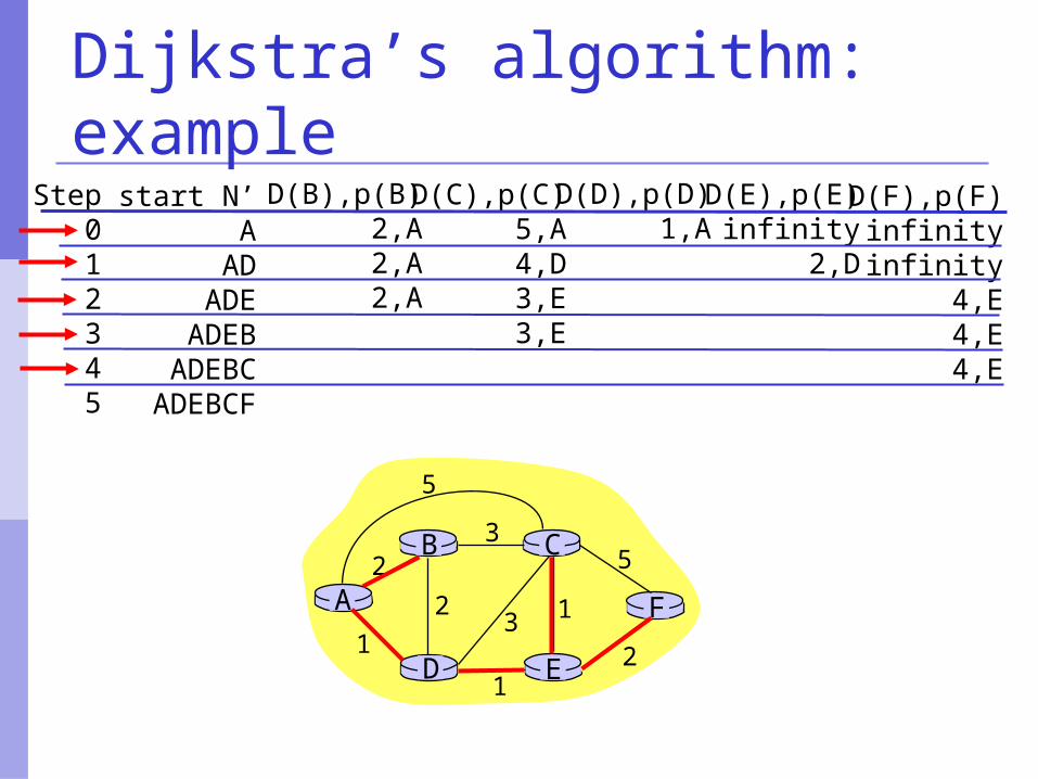
Dijkstra’s algorithm: example
Step012345
start N’A
ADADE
ADEBADEBC
ADEBCF
D(B),p(B)2,A2,A2,A
D(C),p(C)5,A4,D3,E3,E
D(D),p(D)1,A
D(E),p(E)infinity
2,D
D(F),p(F)infinityinfinity
4,E4,E4,E
A
ED
CB
F
2
2
13
1
1
2
53
5
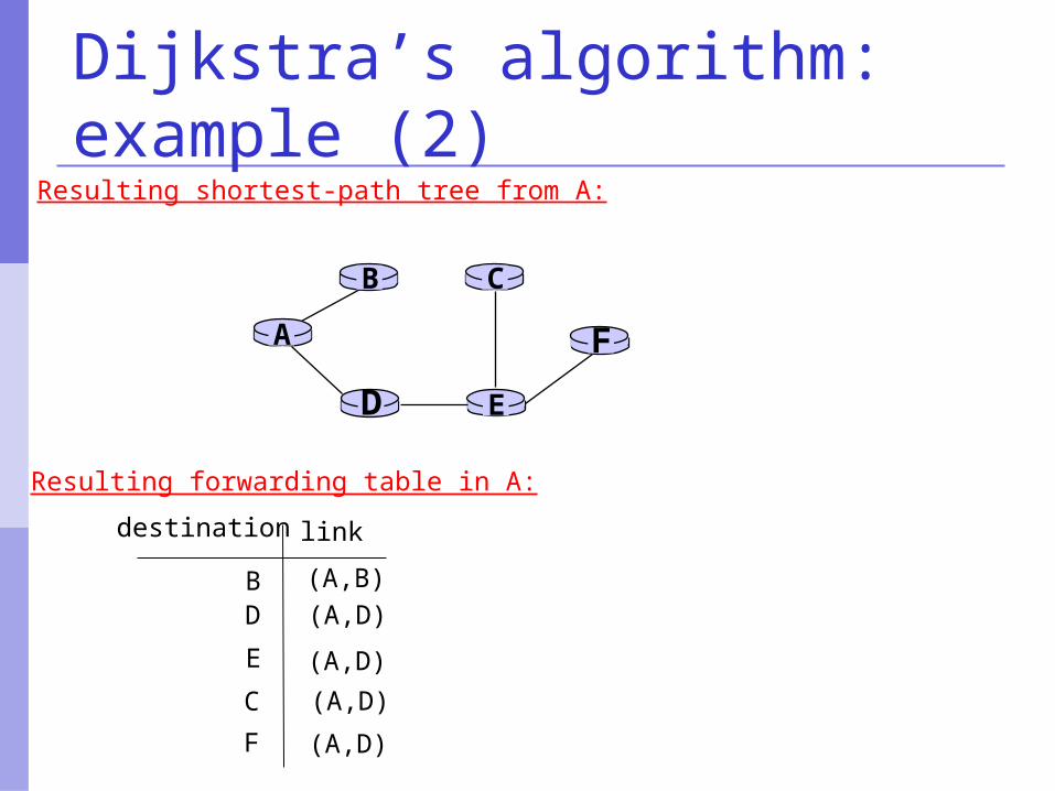
Dijkstra’s algorithm: example (2)
A
ED
CB
F
Resulting shortest-path tree from A:
BD
E
C
F
(A,B)(A,D)
(A,D)
(A,D)
(A,D)
destination link
Resulting forwarding table in A:
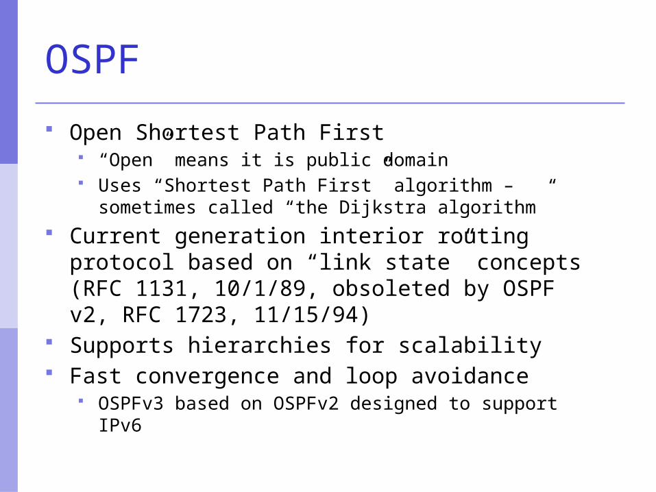
OSPF
Open Shortest Path First “Open” means it is public domain Uses “Shortest Path First” algorithm – sometimes
called “the Dijkstra algorithm” Current generation interior routing protocol
based on “link state” concepts (RFC 1131, 10/1/89, obsoleted by OSPF v2, RFC 1723, 11/15/94)
Supports hierarchies for scalability Fast convergence and loop avoidance
OSPFv3 based on OSPFv2 designed to support IPv6
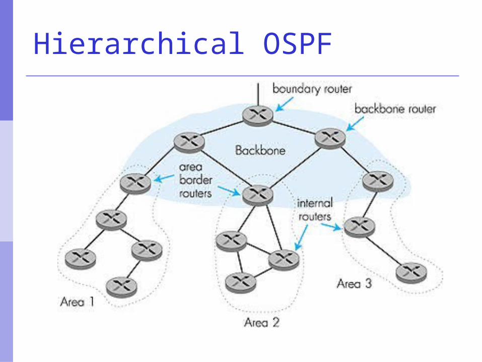
Hierarchical OSPF
Hierarchical OSPF
Two-level hierarchy: local area and backbone. Link-state advertisements only in respective
areas. Nodes in each area have detailed area
topology; only know direction (shortest path) to networks in other areas.
Area Border routers “summarize” distances to networks in the area and advertise them to other Area Border routers.
Backbone routers: run an OSPF routing algorithm limited to the backbone.
Boundary routers: connect to other ASs.
IS-IS
Intermediate-Systemto
Intermediate-System
IS-IS Overview
The Intermediate Systems to Intermediate System Routing Protocol (IS-IS) was originally designed to route the ISO Connectionless Network Protocol (CLNP) . (ISO10589 or RFC 1142)
Adapted for routing IP in addition to CLNP (RFC1195) as Integrated or Dual IS-IS
IS-IS is a Link State Protocol similar to the Open Shortest Path First (OSPF). OSPF supports only IP
IS-IS Overview
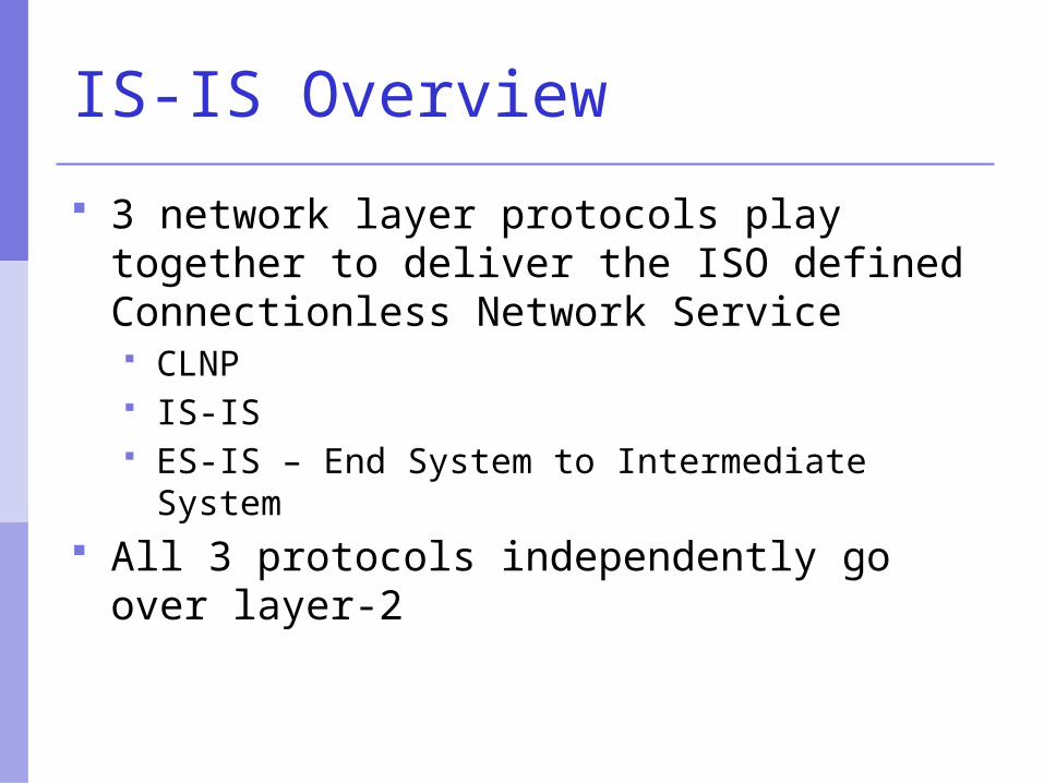
3 network layer protocols play together to deliver the ISO defined Connectionless Network Service CLNP IS-IS ES-IS – End System to Intermediate System
All 3 protocols independently go over layer-2
IS-IS Overview
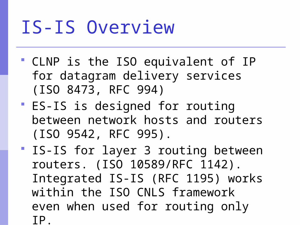
CLNP is the ISO equivalent of IP for datagram delivery services (ISO 8473, RFC 994)
ES-IS is designed for routing between network hosts and routers (ISO 9542, RFC 995).
IS-IS for layer 3 routing between routers. (ISO 10589/RFC 1142). Integrated IS-IS (RFC 1195) works within the ISO CNLS framework even when used for routing only IP.
IS-IS Overview
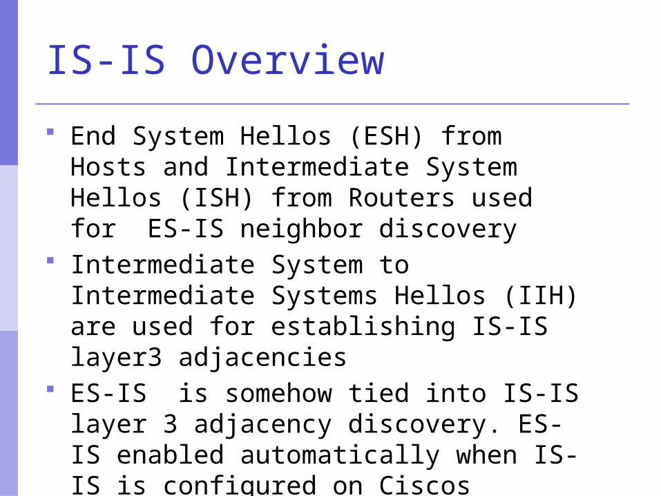
End System Hellos (ESH) from Hosts and Intermediate System Hellos (ISH) from Routers used for ES-IS neighbor discovery
Intermediate System to Intermediate Systems Hellos (IIH) are used for establishing IS-IS layer3 adjacencies
ES-IS is somehow tied into IS-IS layer 3 adjacency discovery. ES-IS enabled automatically when IS-IS is configured on Ciscos
Link State Algorithm
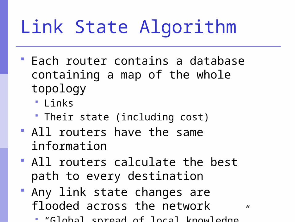
Each router contains a database containing a map of the whole topology Links Their state (including cost)
All routers have the same information All routers calculate the best path to
every destination Any link state changes are flooded
across the network “Global spread of local knowledge”
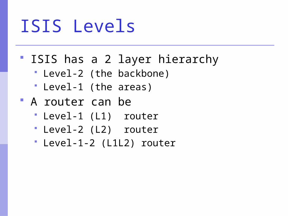
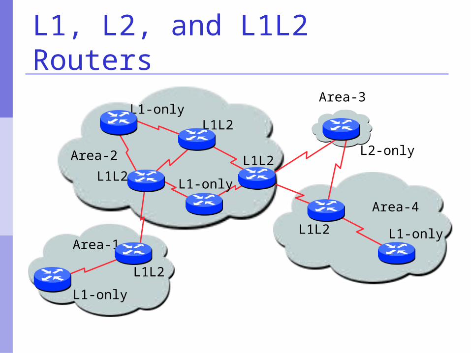
ISIS Levels
ISIS has a 2 layer hierarchy Level-2 (the backbone) Level-1 (the areas)
A router can be Level-1 (L1) router Level-2 (L2) router Level-1-2 (L1L2) router
L1L2
L1L2
L1L2
L1L2
L1L2
L1-only
L2-only
L1-only
Area-2
Area-1
Area-3
Area-4
L1-only
L1-only
L1, L2, and L1L2 Routers
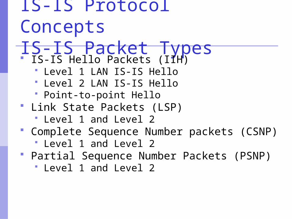
IS-IS Protocol Concepts IS-IS Packet Types IS-IS Hello Packets (IIH)
Level 1 LAN IS-IS Hello Level 2 LAN IS-IS Hello Point-to-point Hello
Link State Packets (LSP) Level 1 and Level 2
Complete Sequence Number packets (CSNP) Level 1 and Level 2
Partial Sequence Number Packets (PSNP) Level 1 and Level 2
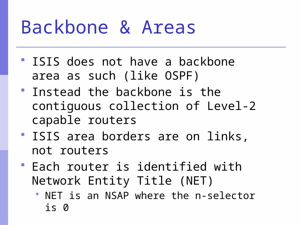
Backbone & Areas
ISIS does not have a backbone area as such (like OSPF)
Instead the backbone is the contiguous collection of Level-2 capable routers
ISIS area borders are on links, not routers
Each router is identified with Network Entity Title (NET) NET is an NSAP where the n-selector is 0
3. CLNS Addressing
NSAP Format AFI Values Requirements and Caveats Examples Globally unique NSAPs
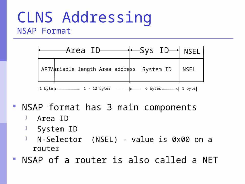
CLNS AddressingNSAP Format
System ID NSELAFI Variable length Area address
6 bytes 1 byte1 byte 1 - 12 bytes
NSAP format has 3 main components– Area ID– System ID– N-Selector (NSEL) - value is 0x00 on a router
NSAP of a router is also called a NET
Area ID Sys ID NSEL
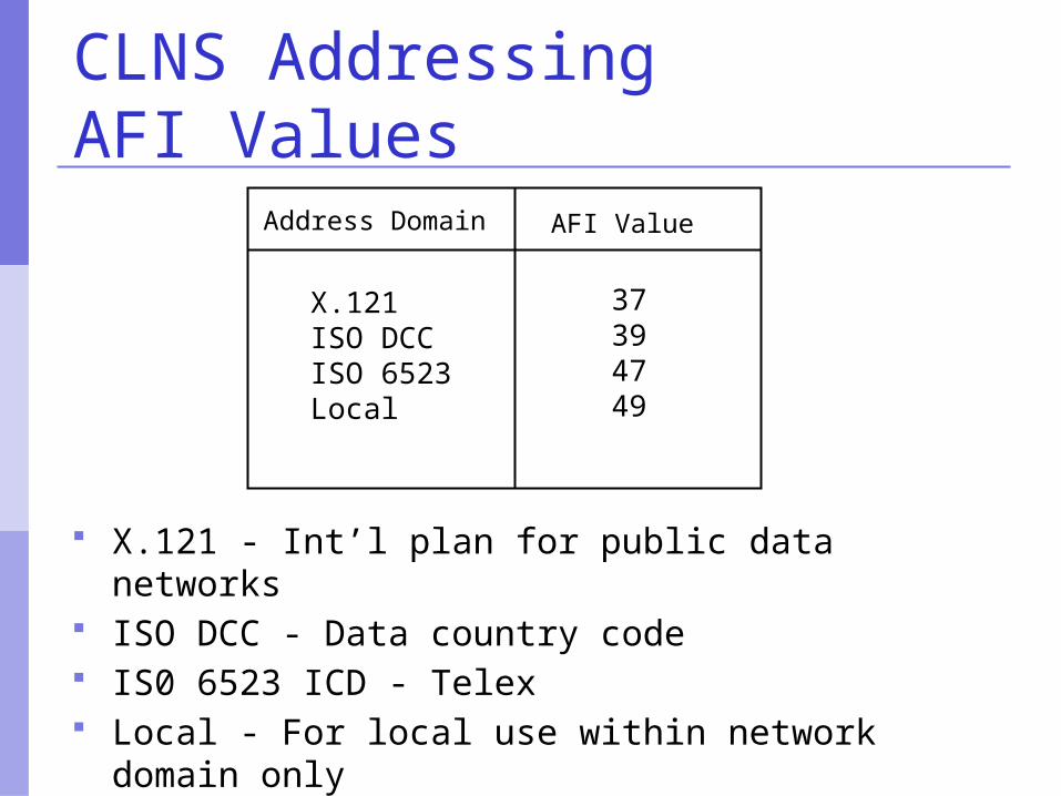
CLNS AddressingAFI Values
X.121 - Int’l plan for public data networks ISO DCC - Data country code IS0 6523 ICD - Telex Local - For local use within network domain
only
Address Domain AFI Value
X.121ISO DCCISO 6523Local
37394749
CLNS AddressingRequirements and Caveats At least one NSAP is required per node All routers in the same area must have
a common Area ID Each node in an area must have a
unique System ID All level 2 routers in a domain must
have unique System IDs relative to each other
All systems belonging to a given domain must have System IDs of the same length in their NSAP addresses
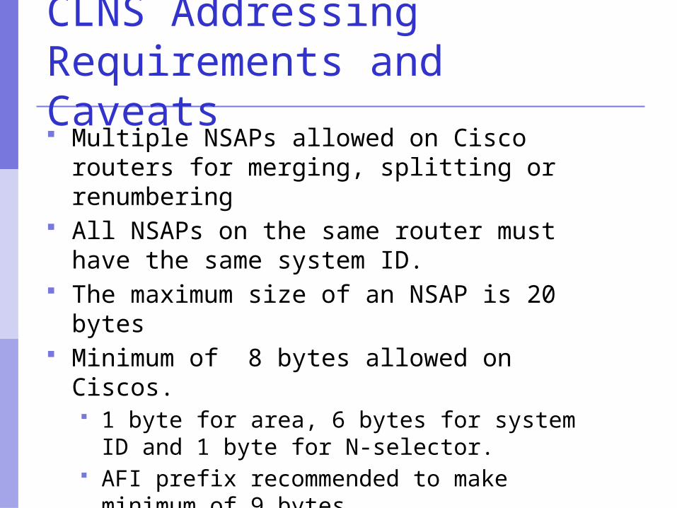
CLNS AddressingRequirements and Caveats Multiple NSAPs allowed on Cisco routers for
merging, splitting or renumbering All NSAPs on the same router must have
the same system ID. The maximum size of an NSAP is 20 bytes Minimum of 8 bytes allowed on Ciscos.
1 byte for area, 6 bytes for system ID and 1 byte for N-selector.
AFI prefix recommended to make minimum of 9 bytes
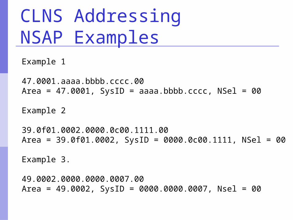
CLNS AddressingNSAP Examples
Example 1
47.0001.aaaa.bbbb.cccc.00Area = 47.0001, SysID = aaaa.bbbb.cccc, NSel = 00
Example 2
39.0f01.0002.0000.0c00.1111.00Area = 39.0f01.0002, SysID = 0000.0c00.1111, NSel = 00
Example 3.
49.0002.0000.0000.0007.00Area = 49.0002, SysID = 0000.0000.0007, Nsel = 00
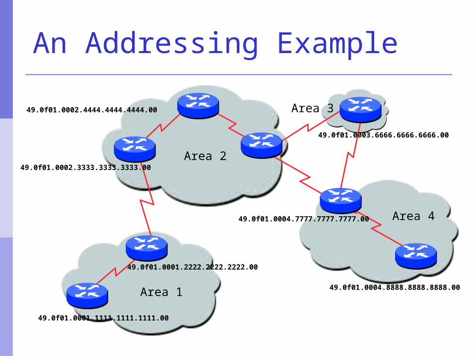
49.0f01.0002.3333.3333.3333.00
49.0f01.0001.2222.2222.2222.00
49.0f01.0001.1111.1111.1111.00
49.0f01.0004.7777.7777.7777.00
49.0f01.0003.6666.6666.6666.00
49.0f01.0004.8888.8888.8888.00
49.0f01.0002.4444.4444.4444.00
Area 1
Area 3
Area 4
Area 2
An Addressing Example
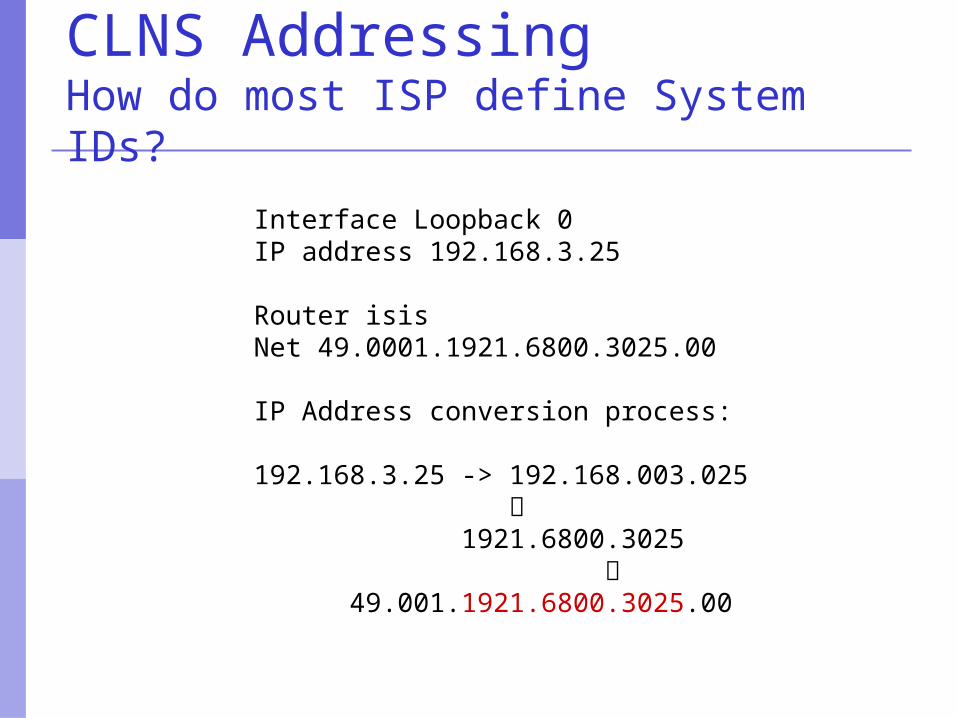
CLNS AddressingHow do most ISP define System IDs?
Interface Loopback 0IP address 192.168.3.25
Router isisNet 49.0001.1921.6800.3025.00
IP Address conversion process:
192.168.3.25 -> 192.168.003.025
1921.6800.3025
49.001.1921.6800.3025.00
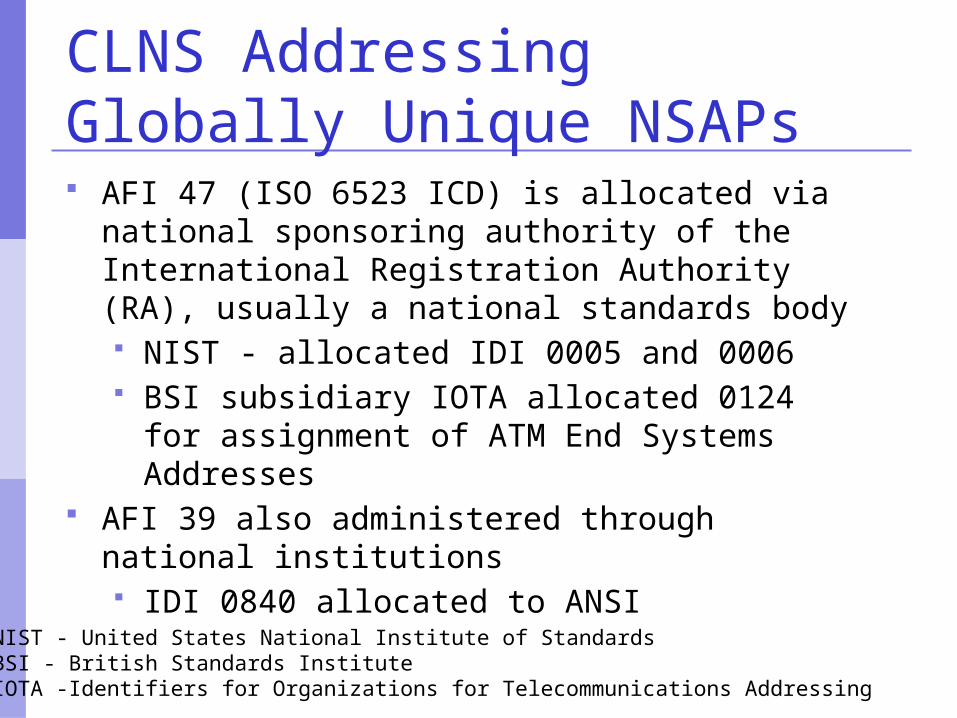
CLNS AddressingGlobally Unique NSAPs AFI 47 (ISO 6523 ICD) is allocated via national
sponsoring authority of the International Registration Authority (RA), usually a national standards body NIST - allocated IDI 0005 and 0006 BSI subsidiary IOTA allocated 0124 for
assignment of ATM End Systems Addresses AFI 39 also administered through national
institutions IDI 0840 allocated to ANSI
NIST - United States National Institute of StandardsBSI - British Standards InstituteIOTA -Identifiers for Organizations for Telecommunications Addressing
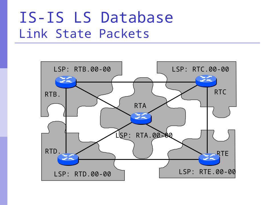
IS-IS LS DatabaseLink State Packets
LSP: RTC.00-00
RTD.
LSP: RTE.00-00
RTC
RTE
LSP: RTA.00-00
RTA
LSP: RTD.00-00
RTB.
LSP: RTB.00-00
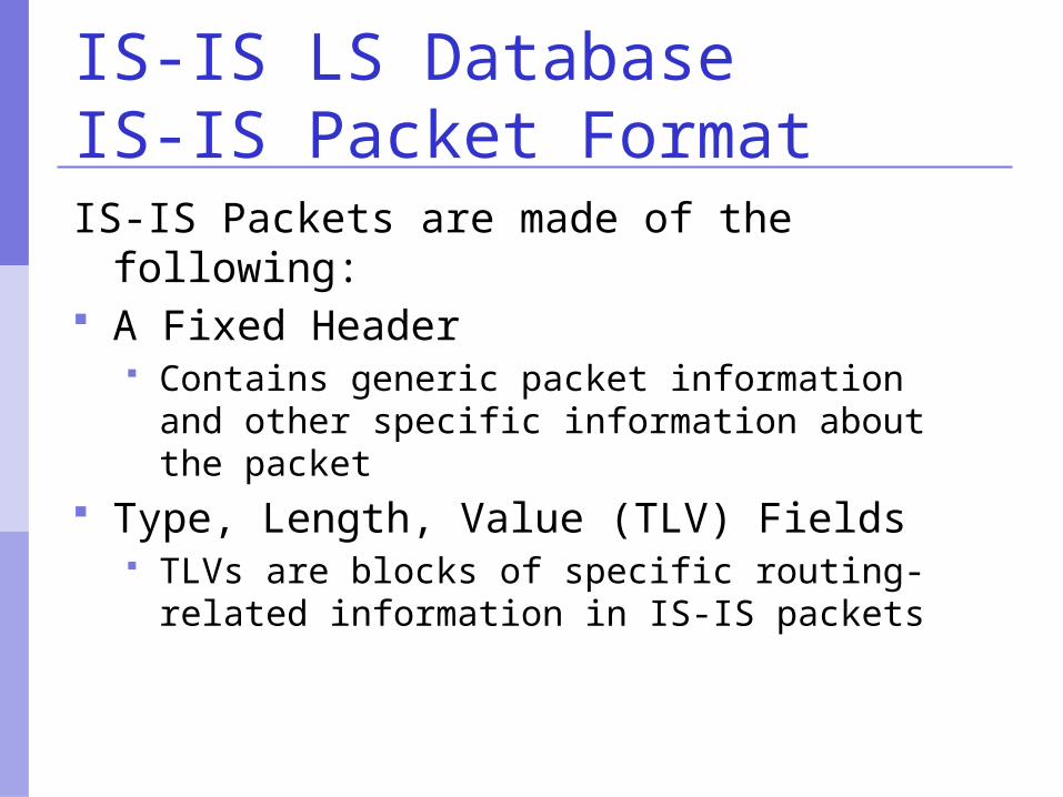
IS-IS LS Database IS-IS Packet FormatIS-IS Packets are made of the following: A Fixed Header
Contains generic packet information and other specific information about the packet
Type, Length, Value (TLV) Fields TLVs are blocks of specific routing-related
information in IS-IS packets
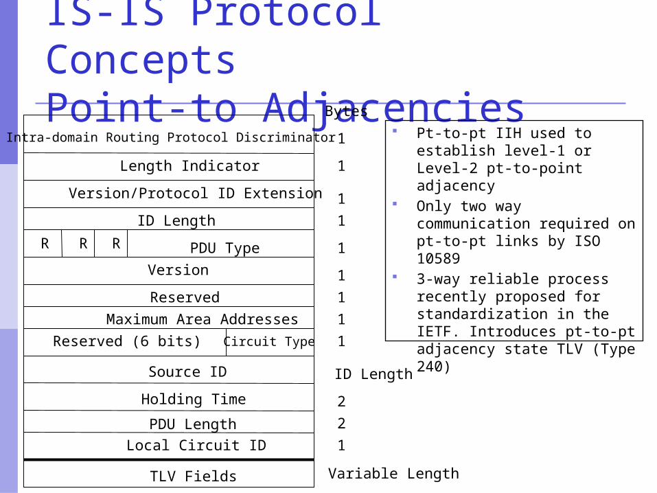
IS-IS Protocol Concepts Point-to Adjacencies
Pt-to-pt IIH used to establish level-1 or Level-2 pt-to-point adjacency
Only two way communication required on pt-to-pt links by ISO 10589
3-way reliable process recently proposed for standardization in the IETF. Introduces pt-to-pt adjacency state TLV (Type 240)
Intra-domain Routing Protocol Discriminator
Length Indicator
TLV Fields
Version/Protocol ID Extension
ID Length
R R R PDU Type
Version
Reserved
Maximum Area Addresses
Reserved (6 bits)
Source ID
Holding Time
PDU LengthLocal Circuit ID
Circuit Type
Bytes
1
1
1
1
1
1
1
1
2
1
ID Length
2
1
Variable Length
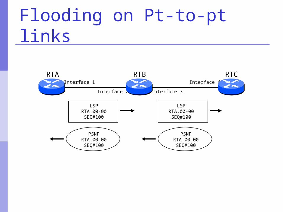
Flooding on Pt-to-pt links
RTA RTB RTCInterface 1
Interface 2 Interface 3
Interface 4
PSNPRTA.00-00SEQ#100
PSNPRTA.00-00SEQ#100
LSPRTA.00-00SEQ#100
LSPRTA.00-00SEQ#100
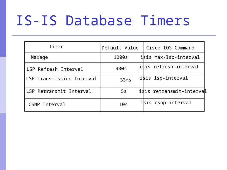
IS-IS Database Timers
Timer Default Value Cisco IOS Command
Maxage
LSP Refresh Interval
LSP Transmission Interval
LSP Retransmit Interval
CSNP Interval
1200s
900s
33ms
5s
10s
isis max-lsp-interval
isis refresh-interval
isis lsp-interval
isis retransmit-interval
isis csnp-interval
SPF Algorithm
In default mode, SPF process runs no frequent than every 5s
Full SPF is run when topology changes When leaf elements such as IP prefixes
change, routing table is adjusted with Partial Route Calculation (PRC)
PRC evaluates only routes that changed hence less CPU intensive and relatively fast
SPF Algorithm
Duration of SPF depends on many factors such as: Number of nodes Number of links Number of IP prefixes Degree of mesh (especially for NBMA) Speed of Route Processor
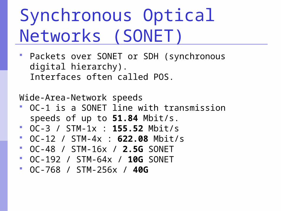
Synchronous Optical Networks (SONET) Packets over SONET or SDH (synchronous digital
hierarchy).Interfaces often called POS.
Wide-Area-Network speeds OC-1 is a SONET line with transmission speeds of
up to 51.84 Mbit/s. OC-3 / STM-1x : 155.52 Mbit/s OC-12 / STM-4x : 622.08 Mbit/s OC-48 / STM-16x / 2.5G SONET OC-192 / STM-64x / 10G SONET OC-768 / STM-256x / 40G
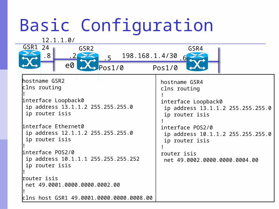
Basic Configuration
.6.5 198.168.1.4/30GSR1 GSR4
Pos1/0 Pos1/0
GSR212.1.1.0/24
.2.8
hostname GSR2clns routing!interface Loopback0 ip address 13.1.1.2 255.255.255.0 ip router isis
interface Ethernet0 ip address 12.1.1.2 255.255.255.0 ip router isis!interface POS2/0 ip address 10.1.1.1 255.255.255.252 ip router isis !router isis net 49.0001.0000.0000.0002.00!clns host GSR1 49.0001.0000.0000.0008.00
hostname GSR4clns routing!interface Loopback0 ip address 13.1.1.2 255.255.255.0 ip router isis !interface POS2/0 ip address 10.1.1.2 255.255.255.0 ip router isis !router isis net 49.0002.0000.0000.0004.00
e0
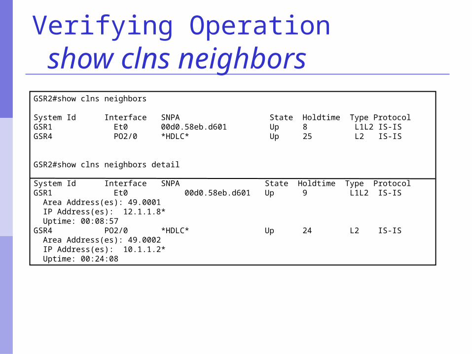
Verifying Operation show clns neighborsGSR2#show clns neighbors
System Id Interface SNPA State Holdtime Type ProtocolGSR1 Et0 00d0.58eb.d601 Up 8 L1L2 IS-ISGSR4 PO2/0 *HDLC* Up 25 L2 IS-IS
GSR2#show clns neighbors detail
System Id Interface SNPA State Holdtime Type ProtocolGSR1 Et0 00d0.58eb.d601 Up 9 L1L2 IS-IS Area Address(es): 49.0001 IP Address(es): 12.1.1.8* Uptime: 00:08:57 GSR4 PO2/0 *HDLC* Up 24 L2 IS-IS Area Address(es): 49.0002 IP Address(es): 10.1.1.2* Uptime: 00:24:08
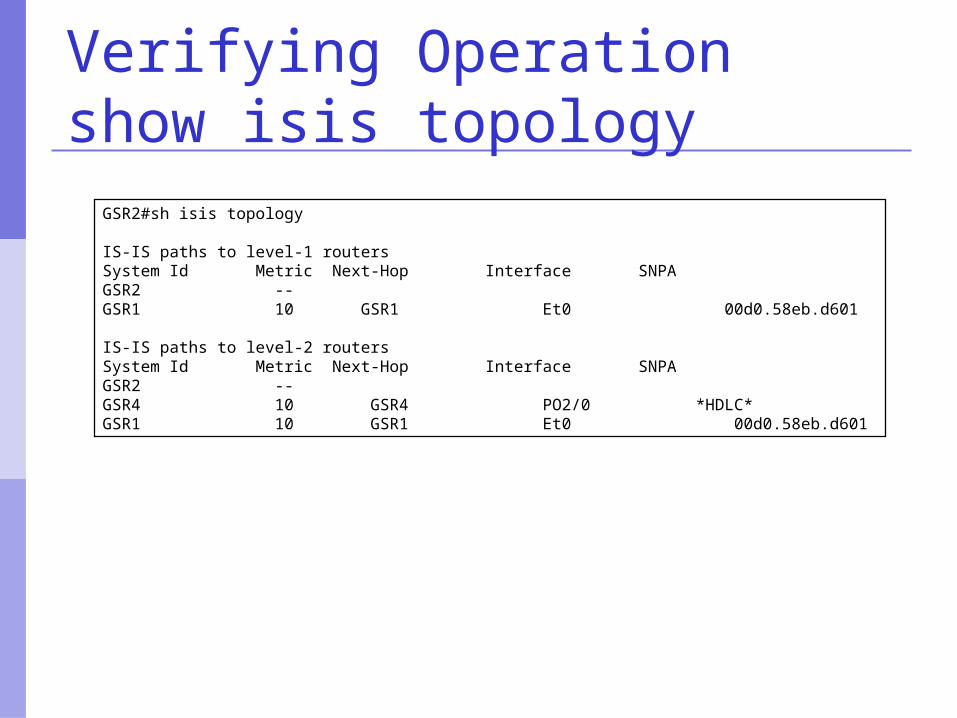
Verifying Operationshow isis topology
GSR2#sh isis topology
IS-IS paths to level-1 routersSystem Id Metric Next-Hop Interface SNPAGSR2 --GSR1 10 GSR1 Et0 00d0.58eb.d601
IS-IS paths to level-2 routersSystem Id Metric Next-Hop Interface SNPAGSR2 --GSR4 10 GSR4 PO2/0 *HDLC*GSR1 10 GSR1 Et0 00d0.58eb.d601
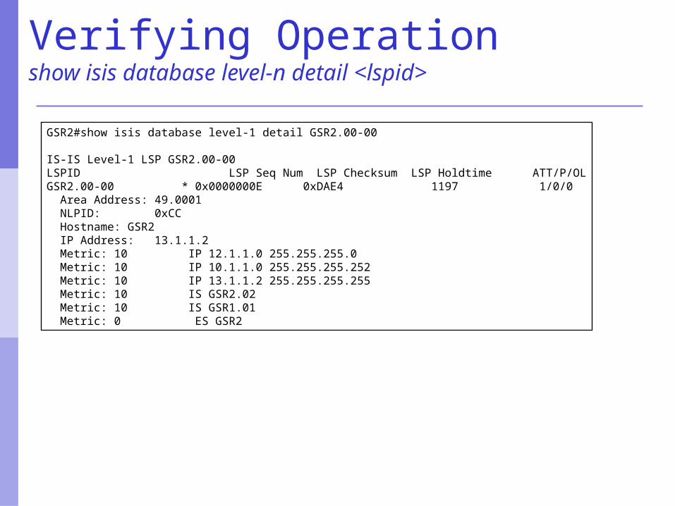
Verifying Operationshow isis database level-n detail <lspid>
GSR2#show isis database level-1 detail GSR2.00-00
IS-IS Level-1 LSP GSR2.00-00LSPID LSP Seq Num LSP Checksum LSP Holdtime ATT/P/OLGSR2.00-00 * 0x0000000E 0xDAE4 1197 1/0/0 Area Address: 49.0001 NLPID: 0xCC Hostname: GSR2 IP Address: 13.1.1.2 Metric: 10 IP 12.1.1.0 255.255.255.0 Metric: 10 IP 10.1.1.0 255.255.255.252 Metric: 10 IP 13.1.1.2 255.255.255.255 Metric: 10 IS GSR2.02 Metric: 10 IS GSR1.01 Metric: 0 ES GSR2
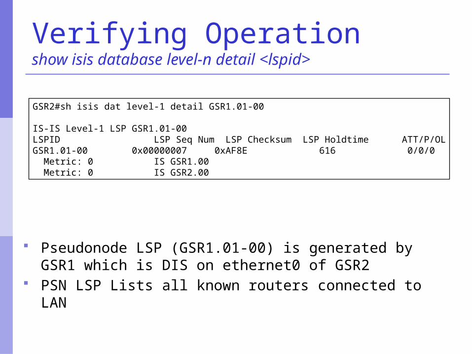
Verifying Operationshow isis database level-n detail <lspid>
GSR2#sh isis dat level-1 detail GSR1.01-00
IS-IS Level-1 LSP GSR1.01-00LSPID LSP Seq Num LSP Checksum LSP Holdtime ATT/P/OLGSR1.01-00 0x00000007 0xAF8E 616 0/0/0 Metric: 0 IS GSR1.00 Metric: 0 IS GSR2.00
Pseudonode LSP (GSR1.01-00) is generated by GSR1 which is DIS on ethernet0 of GSR2
PSN LSP Lists all known routers connected to LAN
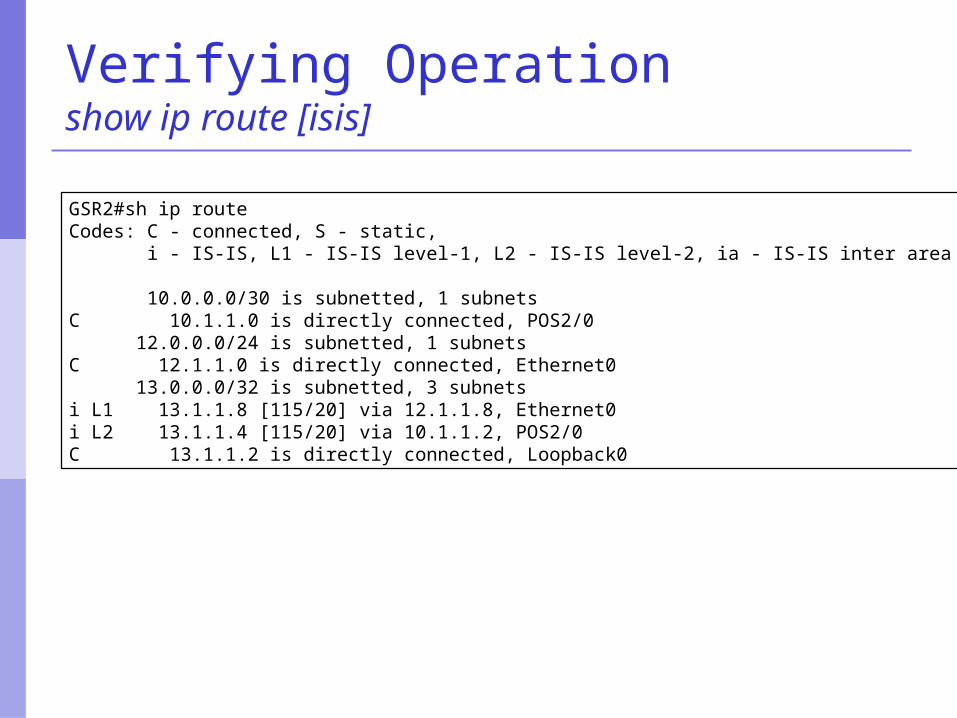
Verifying Operationshow ip route [isis]
GSR2#sh ip routeCodes: C - connected, S - static, i - IS-IS, L1 - IS-IS level-1, L2 - IS-IS level-2, ia - IS-IS inter area 10.0.0.0/30 is subnetted, 1 subnetsC 10.1.1.0 is directly connected, POS2/0 12.0.0.0/24 is subnetted, 1 subnetsC 12.1.1.0 is directly connected, Ethernet0 13.0.0.0/32 is subnetted, 3 subnetsi L1 13.1.1.8 [115/20] via 12.1.1.8, Ethernet0i L2 13.1.1.4 [115/20] via 10.1.1.2, POS2/0C 13.1.1.2 is directly connected, Loopback0
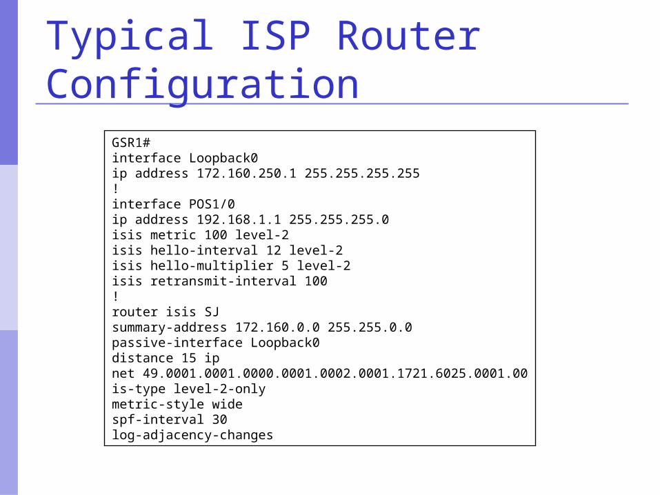
Typical ISP Router Configuration
GSR1#interface Loopback0ip address 172.160.250.1 255.255.255.255!interface POS1/0ip address 192.168.1.1 255.255.255.0isis metric 100 level-2isis hello-interval 12 level-2isis hello-multiplier 5 level-2isis retransmit-interval 100!router isis SJsummary-address 172.160.0.0 255.255.0.0 passive-interface Loopback0distance 15 ipnet 49.0001.0001.0000.0001.0002.0001.1721.6025.0001.00is-type level-2-onlymetric-style widespf-interval 30log-adjacency-changes
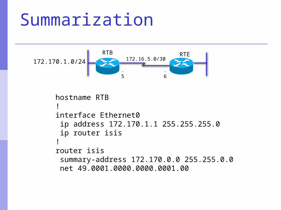
Summarization
.6.5
172.16.5.0/30RTB RTE
172.170.1.0/24
hostname RTB!interface Ethernet0 ip address 172.170.1.1 255.255.255.0 ip router isis!router isis summary-address 172.170.0.0 255.255.0.0 net 49.0001.0000.0000.0001.00
Summarization
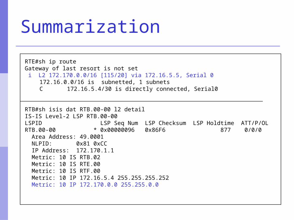
RTE#sh ip routeGateway of last resort is not set i L2 172.170.0.0/16 [115/20] via 172.16.5.5, Serial 0
172.16.0.0/16 is subnetted, 1 subnetsC 172.16.5.4/30 is directly connected, Serial0
RTB#sh isis dat RTB.00-00 l2 detailIS-IS Level-2 LSP RTB.00-00LSPID LSP Seq Num LSP Checksum LSP Holdtime ATT/P/OLRTB.00-00 * 0x00000096 0x86F6 877 0/0/0 Area Address: 49.0001 NLPID: 0x81 0xCC IP Address: 172.170.1.1 Metric: 10 IS RTB.02 Metric: 10 IS RTE.00 Metric: 10 IS RTF.00 Metric: 10 IP 172.16.5.4 255.255.255.252 Metric: 10 IP 172.170.0.0 255.255.0.0
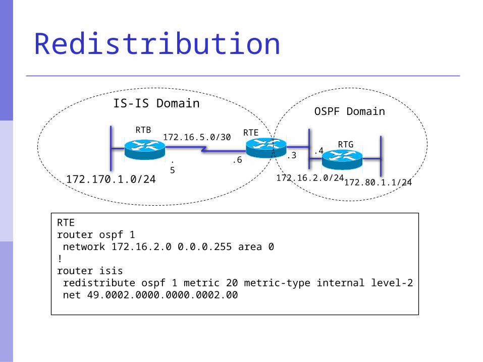
Redistribution
.6.5
172.16.5.0/30RTB RTE
172.170.1.0/24
RTG
IS-IS DomainOSPF Domain
172.80.1.1/24
RTErouter ospf 1 network 172.16.2.0 0.0.0.255 area 0!router isis redistribute ospf 1 metric 20 metric-type internal level-2 net 49.0002.0000.0000.0002.00
172.16.2.0/24
.3 .4
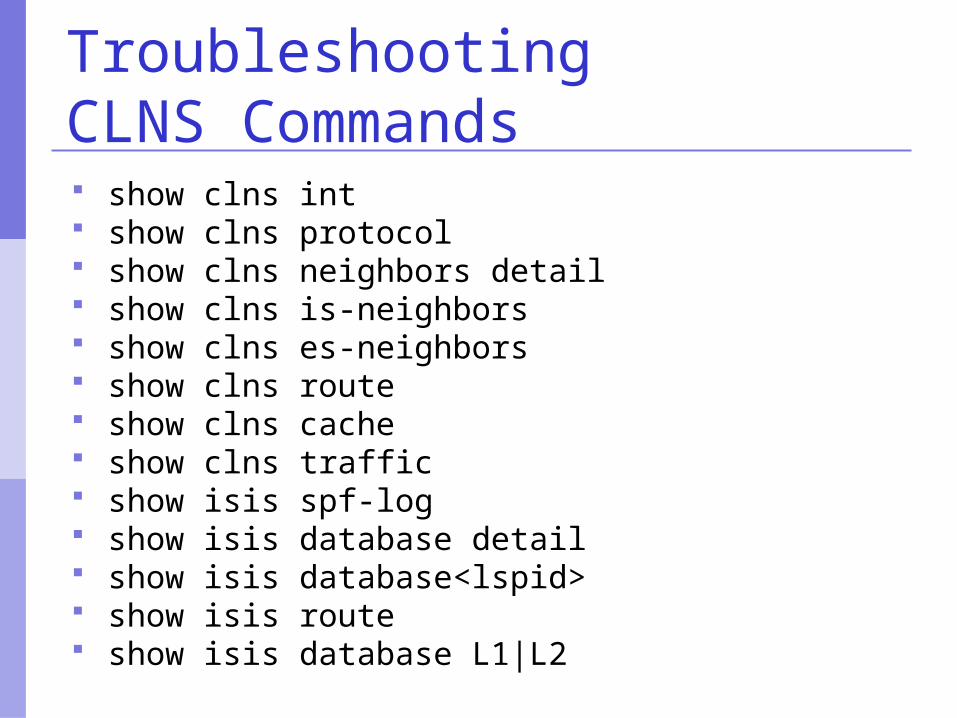
TroubleshootingCLNS Commands show clns int show clns protocol show clns neighbors detail show clns is-neighbors show clns es-neighbors show clns route show clns cache show clns traffic show isis spf-log show isis database detail show isis database<lspid> show isis route show isis database L1|L2
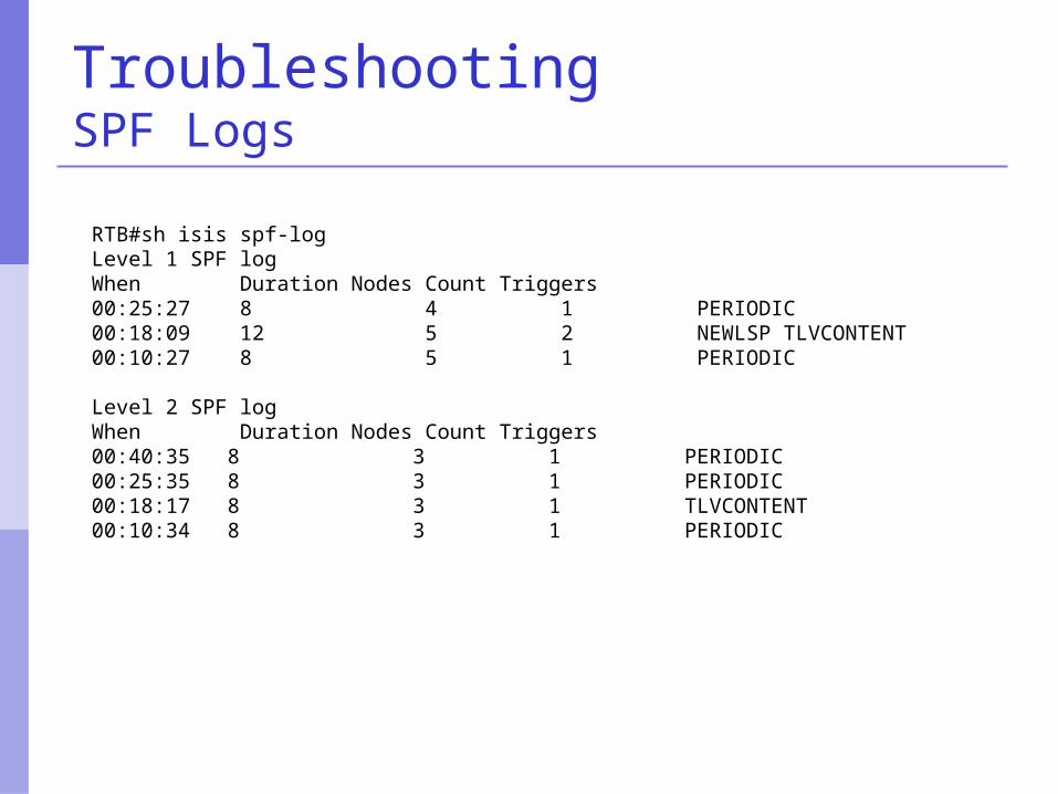
TroubleshootingSPF Logs
RTB#sh isis spf-logLevel 1 SPF logWhen Duration Nodes Count Triggers00:25:27 8 4 1 PERIODIC00:18:09 12 5 2 NEWLSP TLVCONTENT00:10:27 8 5 1 PERIODIC
Level 2 SPF logWhen Duration Nodes Count Triggers00:40:35 8 3 1 PERIODIC00:25:35 8 3 1 PERIODIC00:18:17 8 3 1 TLVCONTENT00:10:34 8 3 1 PERIODIC
Area 49.0001 Area 49.0002
Rtr-C Rtr-B
Rtr-A Rtr-D
L1L2 routers
L1routers
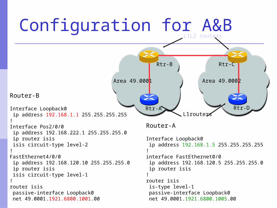
Router-B
Interface Loopback0 ip address 192.168.1.1 255.255.255.255!Interface Pos2/0/0 ip address 192.168.222.1 255.255.255.0 ip router isis isis circuit-type level-2!FastEthernet4/0/0 ip address 192.168.120.10 255.255.255.0 ip router isis isis circuit-type level-1!router isis passive-interface Loopback0 net 49.0001.1921.6800.1001.00
Router-A
Interface Loopback0 ip address 192.168.1.5 255.255.255.255!interface FastEthernet0/0 ip address 192.168.120.5 255.255.255.0 ip router isis!router isis is-type level-1 passive-interface Loopback0 net 49.0001.1921.6800.1005.00
Configuration for A&B
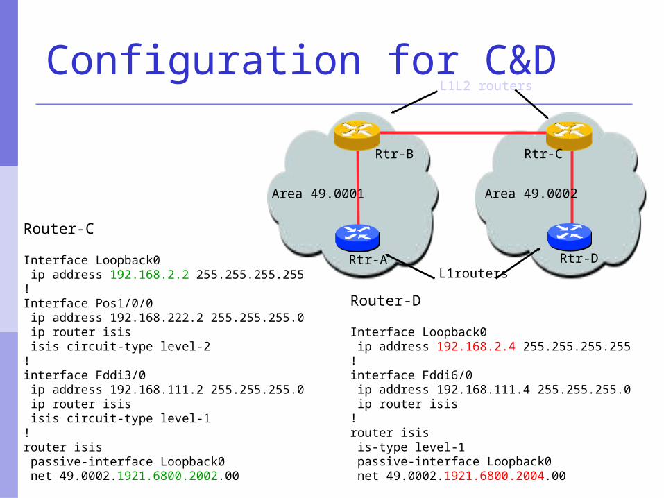
Router-C
Interface Loopback0 ip address 192.168.2.2 255.255.255.255!Interface Pos1/0/0 ip address 192.168.222.2 255.255.255.0 ip router isis isis circuit-type level-2!interface Fddi3/0 ip address 192.168.111.2 255.255.255.0 ip router isis isis circuit-type level-1!router isis passive-interface Loopback0 net 49.0002.1921.6800.2002.00
Router-D
Interface Loopback0 ip address 192.168.2.4 255.255.255.255!interface Fddi6/0 ip address 192.168.111.4 255.255.255.0 ip router isis!router isis is-type level-1 passive-interface Loopback0 net 49.0002.1921.6800.2004.00
Configuration for C&D
Area 49.0001 Area 49.0002
Rtr-C Rtr-B
Rtr-A Rtr-D
L1L2 routers
L1routers
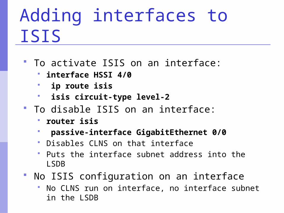
Adding interfaces to ISIS
To activate ISIS on an interface: interface HSSI 4/0 ip route isis isis circuit-type level-2
To disable ISIS on an interface: router isis passive-interface GigabitEthernet 0/0 Disables CLNS on that interface Puts the interface subnet address into the LSDB
No ISIS configuration on an interface No CLNS run on interface, no interface subnet in the
LSDB
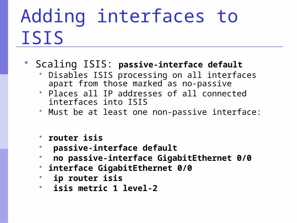
Adding interfaces to ISIS
Scaling ISIS: passive-interface default Disables ISIS processing on all interfaces apart from
those marked as no-passive Places all IP addresses of all connected interfaces into
ISIS Must be at least one non-passive interface:
router isis passive-interface default no passive-interface GigabitEthernet 0/0 interface GigabitEthernet 0/0 ip router isis isis metric 1 level-2
Network Design Issues
As in all IP network designs, the key issue is the addressing lay-out
ISIS supports a large number of routers in a single area
When using areas, use summary-addresses >400 routers in the backbone is quite doable
Border Gateway Protocol
Introduction
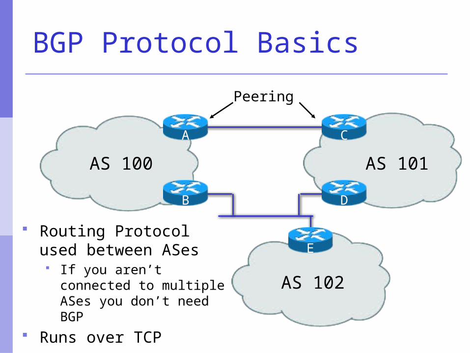
BGP Protocol Basics
Routing Protocol used between ASes If you aren’t connected
to multiple ASes you don’t need BGP
Runs over TCP
AS 100 AS 101
AS 102
E
B D
A C
Peering
Consider a typical small ISP Local network in one country May have multiple POPs in different
cities Line to Internet
International line providing transit connectivity
Very, very expensive international line Doesn’t yet need BGP
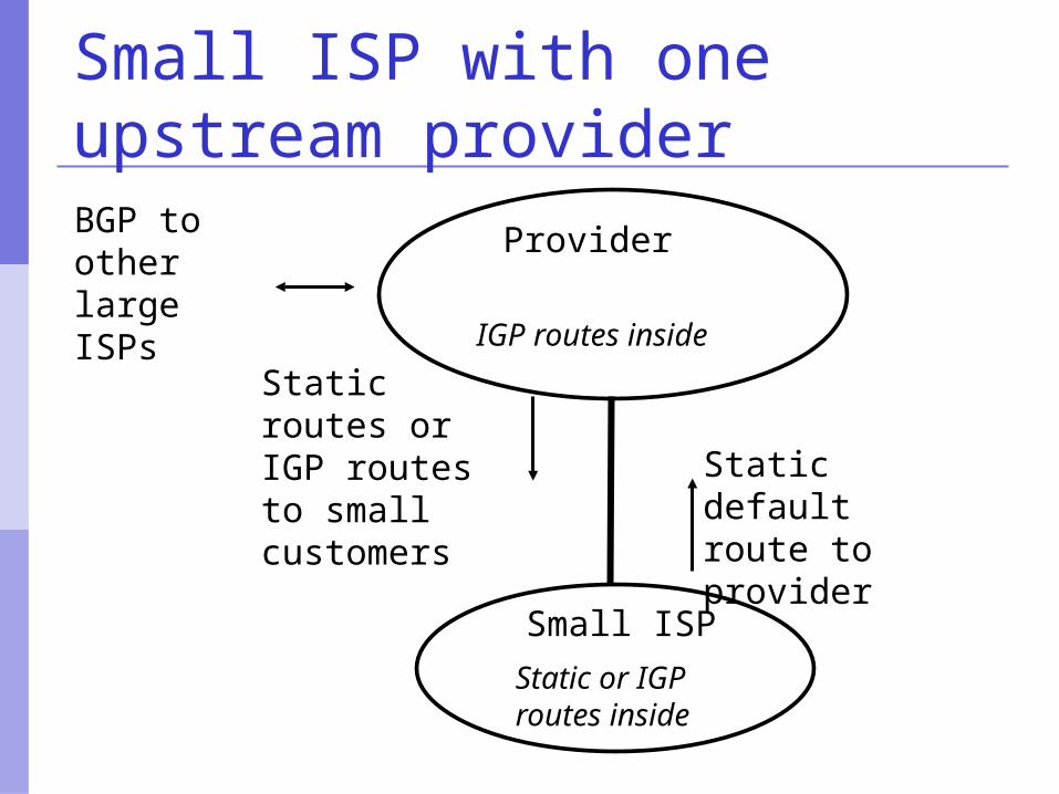
Small ISP with one upstream provider
Provider
Small ISP
Static default route to provider
Static routes or IGP routes to small customers
Static or IGP routes inside
IGP routes inside
BGP to other large ISPs
What happens with other ISPs in the same region/country Similar setup Traffic between you and them goes over
Your expensive line Their expensive line
Traffic can be significant Your customers want to talk to their
customers Same language/culture Local email, discussion lists, web sites
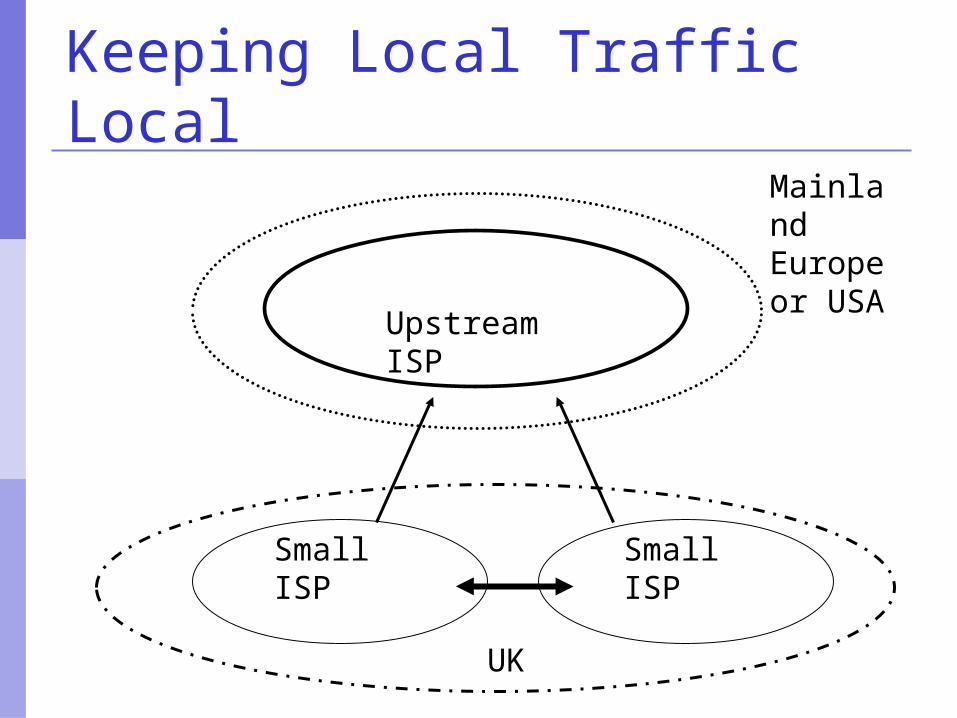
Keeping Local Traffic Local
Upstream ISP
Small ISP
Small ISP
UK
Mainland Europe or USA
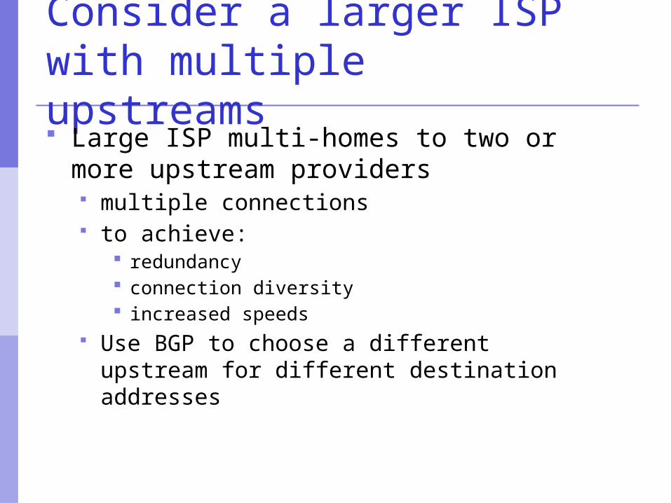
Consider a larger ISP with multiple upstreams Large ISP multi-homes to two or more
upstream providers multiple connections to achieve:
redundancy connection diversity increased speeds
Use BGP to choose a different upstream for different destination addresses
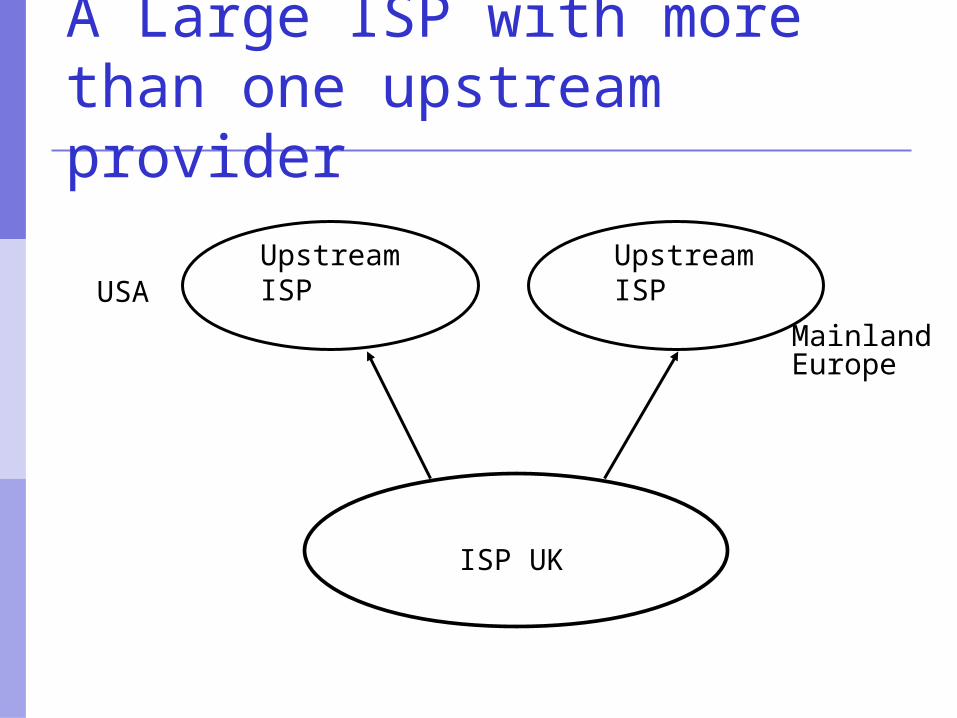
A Large ISP with more than one upstream provider
Upstream ISP
Upstream ISP
MainlandEurope
USA
ISP UK
Terminology: “Policy”
Where do you want your traffic to go? It is difficult to get what you want, but you
can try Control of how you accept and send
routing updates to neighbours Prefer cheaper connections Prefer connections with better latency Load-sharing, etc
“Policy” (continued)
Implementing policy: Accepting routes from some ISPs and not
others Sending some routes to some ISPs and not
to others Preferring routes from some ISPs over those
from other ISPs
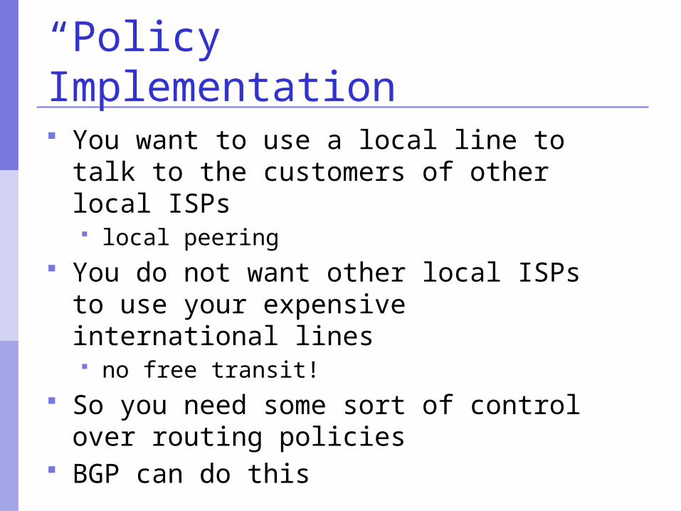
“Policy” Implementation
You want to use a local line to talk to the customers of other local ISPs local peering
You do not want other local ISPs to use your expensive international lines no free transit!
So you need some sort of control over routing policies
BGP can do this
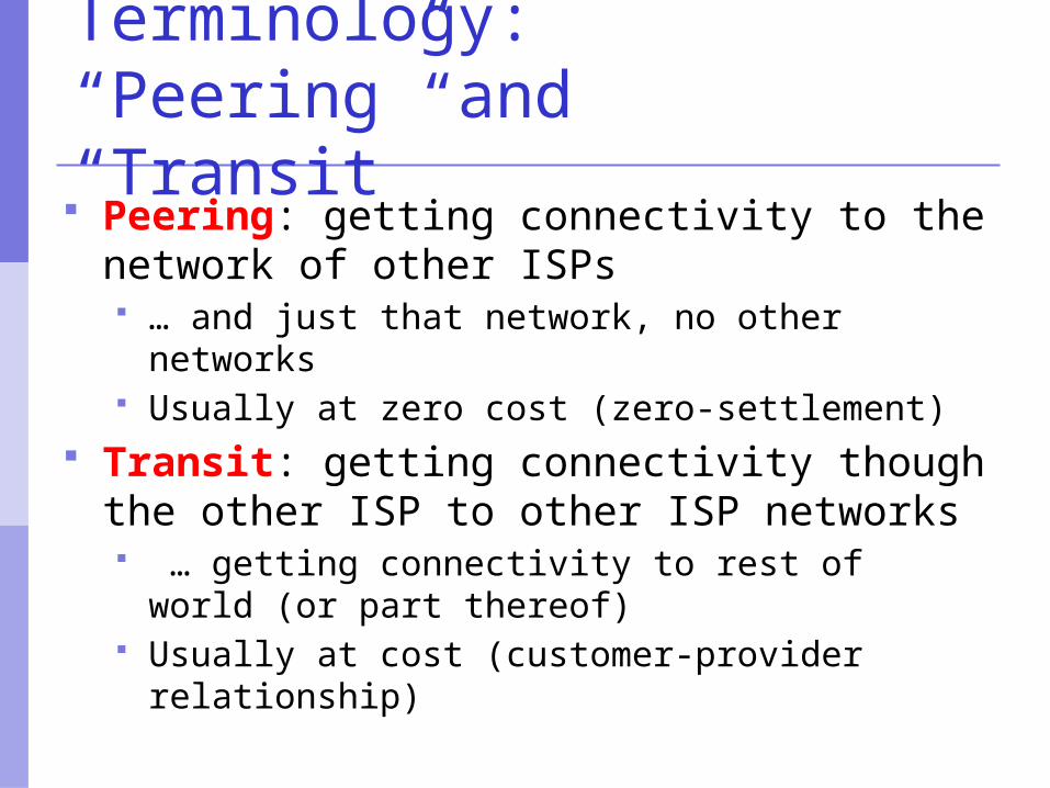
Terminology:“Peering” and “Transit” Peering: getting connectivity to the
network of other ISPs … and just that network, no other networks Usually at zero cost (zero-settlement)
Transit: getting connectivity though the other ISP to other ISP networks … getting connectivity to rest of world (or part
thereof) Usually at cost (customer-provider relationship)

Terminology: “Aggregation” Combining of several smaller blocks of
address space into a larger block For example:
192.168.4.0/24 and 192.168.5.0/24 are contiguous address blocks
They can be combined and represented as 192.168.4.0/23…
…with no loss of information!
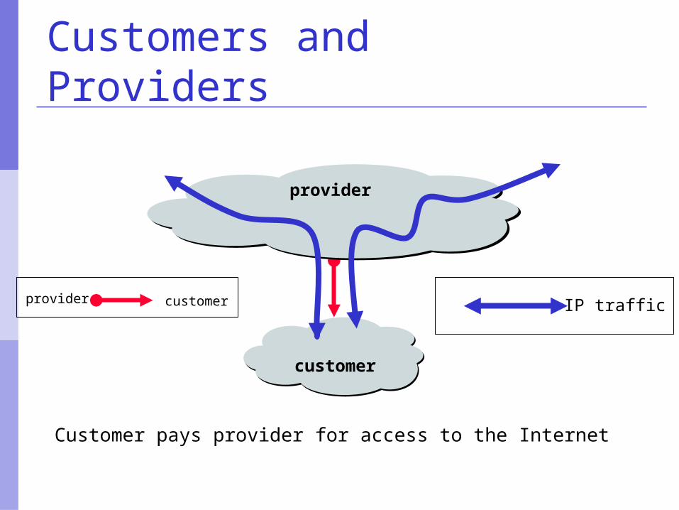
Customers and Providers
Customer pays provider for access to the Internet
provider
customer
IP trafficprovider customer
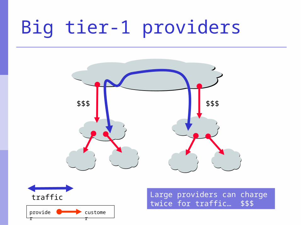
Big tier-1 providers
customerprovider
Large providers can charge twice for traffic… $$$
traffic
$$$$$$
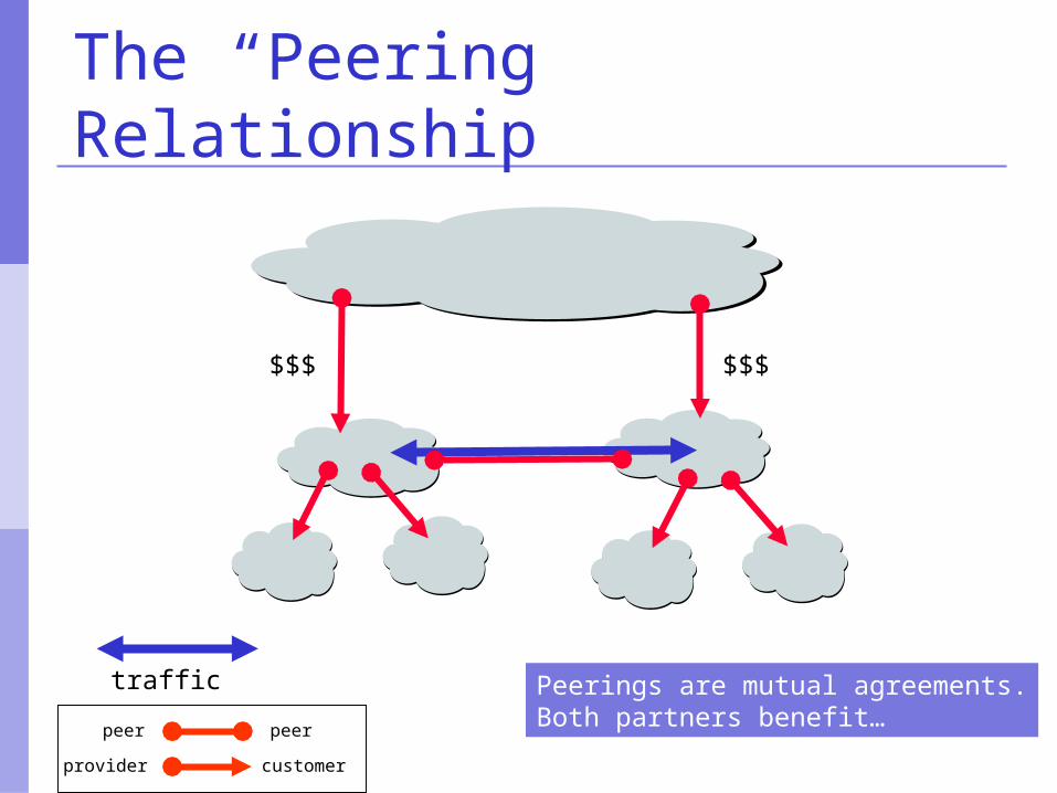
The “Peering” Relationship
Peerings are mutual agreements.Both partners benefit…
traffic
$$$$$$
peer peer
customerprovider
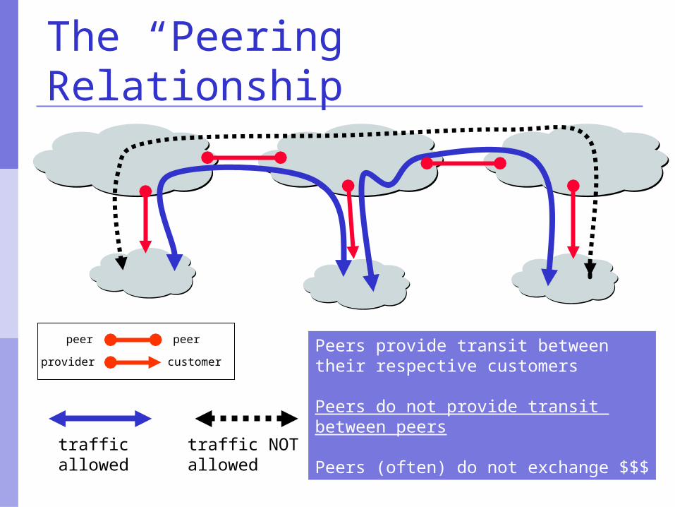
The “Peering” Relationship
peer peer
customerproviderPeers provide transit between their respective customers
Peers do not provide transit between peers
Peers (often) do not exchange $$$trafficallowed
traffic NOTallowed
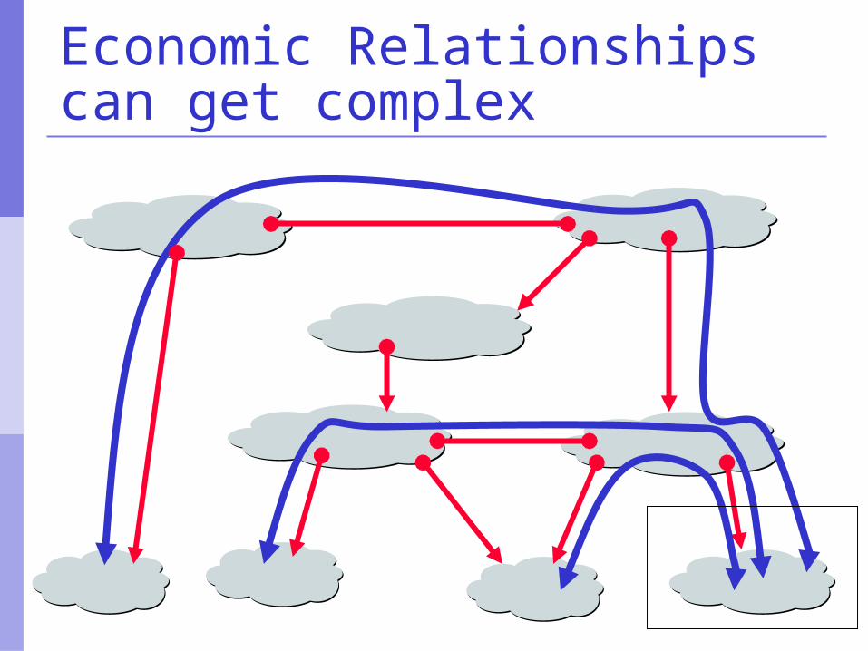
Economic Relationships can get complex
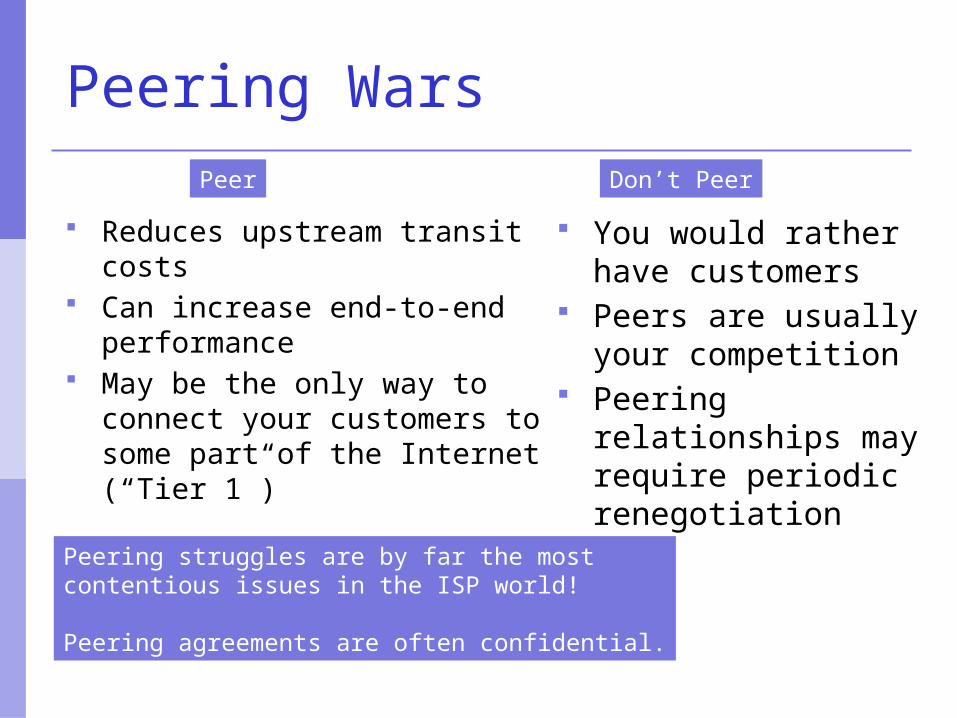
Peering Wars
Reduces upstream transit costs
Can increase end-to-end performance
May be the only way to connect your customers to some part of the Internet (“Tier 1”)
You would rather have customers
Peers are usually your competition
Peering relationships may require periodic renegotiation
Peering struggles are by far the most contentious issues in the ISP world!
Peering agreements are often confidential.
Peer Don’t Peer
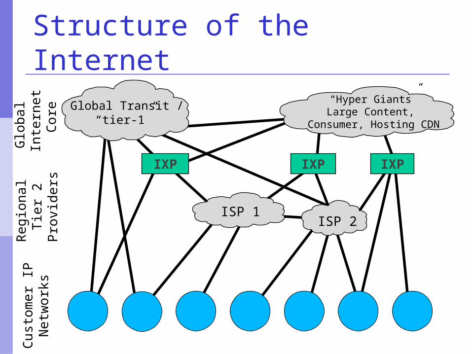
Structure of the Internet
IXP
“Hyper Giants”Large Content,
Consumer, Hosting CDN
Global Transit /“tier-1”
Glo
bal
Inte
rnet
Core
Reg
ion
al
Tie
r 2
Pro
vid
ers
IXP
ISP 1ISP 2
Cu
stom
er
IPN
etw
ork
s
IXP
Summary:Why do I need BGP? Multi-homing – connecting to multiple
providers upstream providers local networks – regional peering to get
local traffic Policy discrimination
controlling how traffic flows do not accidentally provide transit to non-
customers
BGP Part II
BGP Building Blocks
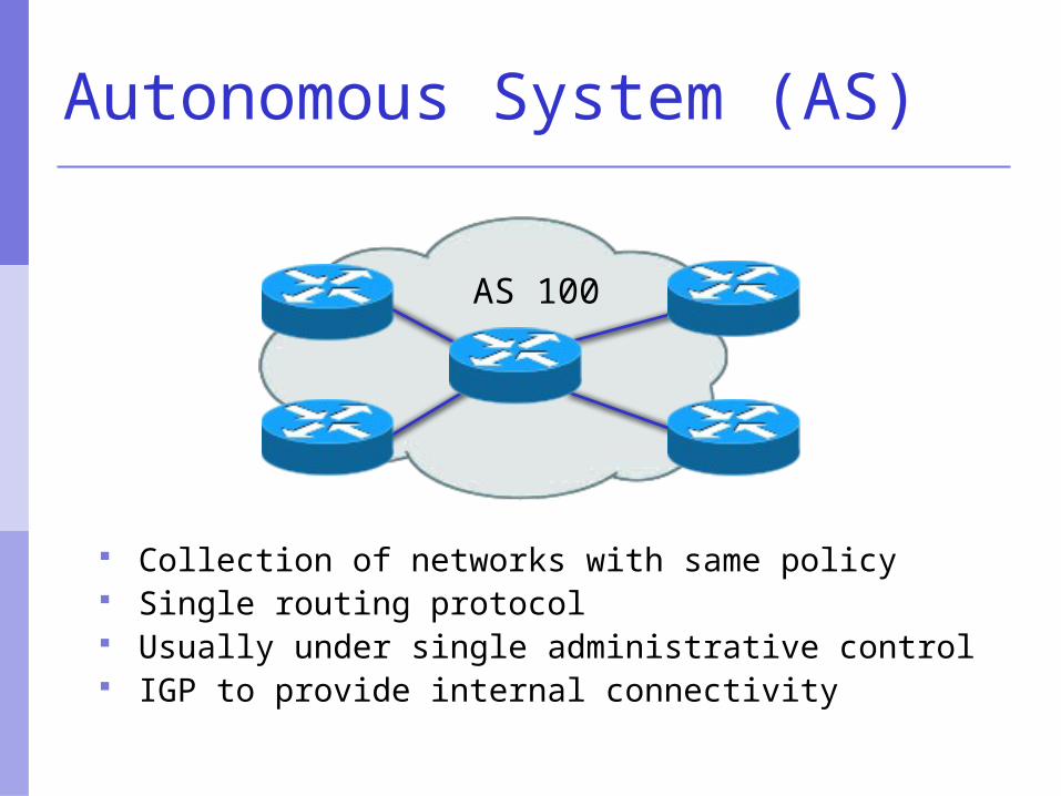
Autonomous System (AS)
Collection of networks with same policy Single routing protocol Usually under single administrative control IGP to provide internal connectivity
AS 100
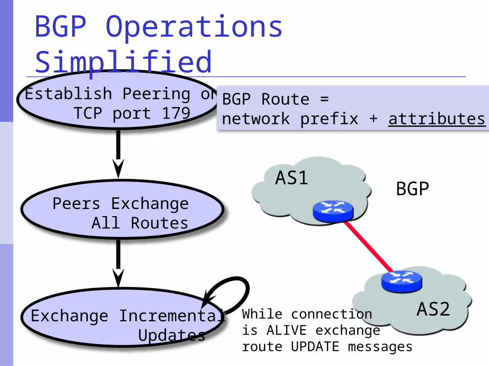
Establish Peering on TCP port 179
Peers Exchange All Routes
Exchange Incremental Updates
AS1
AS2While connection is ALIVE exchangeroute UPDATE messages
BGP
BGP Route = network prefix + attributes
BGP Operations Simplified
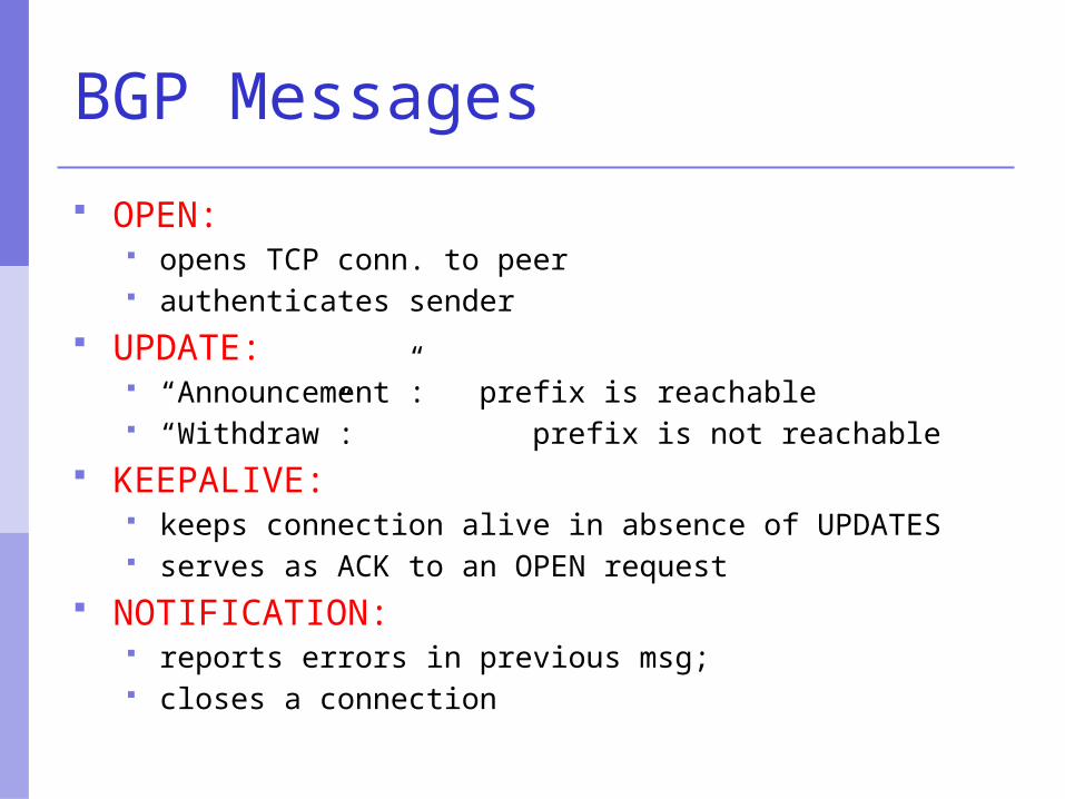
BGP Messages
OPEN: opens TCP conn. to peer authenticates sender
UPDATE: “Announcement”: prefix is reachable “Withdraw”: prefix is not reachable
KEEPALIVE: keeps connection alive in absence of UPDATES serves as ACK to an OPEN request
NOTIFICATION: reports errors in previous msg; closes a connection
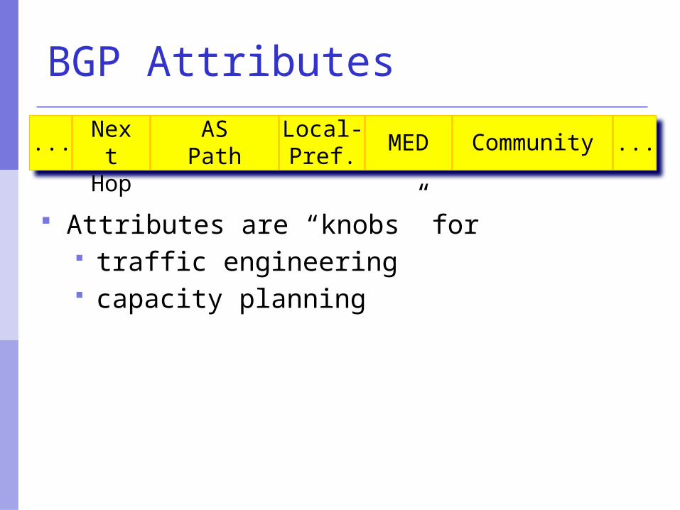
Next
Hop
AS Path
...MEDLocal-Pref.
... Community
BGP Attributes
Attributes are “knobs” for traffic engineering capacity planning
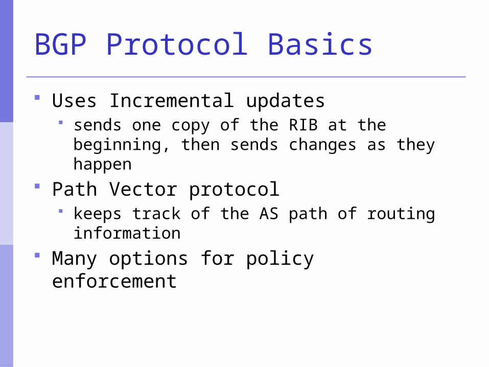
BGP Protocol Basics
Uses Incremental updates sends one copy of the RIB at the beginning,
then sends changes as they happen Path Vector protocol
keeps track of the AS path of routing information
Many options for policy enforcement
Terminology
Neighbour Configured BGP peer
NLRI/Prefix NLRI – network layer reachability information Reachability information for an IP address & mask
Router-ID 32 bit integer to uniquely identify router Comes from Loopback or Highest IP address
configured on the router Route/Path
NLRI advertised by a neighbour
Terminology
Transit – carrying network traffic across a network, usually for a fee
Peering – exchanging routing information and traffic your customers and your peers’ customers network
information only. not your peers’ peers; not your peers’ providers.
Peering also has another meaning: BGP neighbour, whether or not transit is provided
Default – where to send traffic when there is no explicit route in the routing table
BGP Basics …
Each AS originates a set of NLRI (routing announcements)
NLRI is exchanged between BGP peers Can have multiple paths for a given
prefix BGP picks the best path and installs in
the IP forwarding table Policies applied (through attributes)
influences BGP path selection
Interior BGP vs. Exterior BGP
Interior BGP (iBGP) Between routers in the same AS Often between routers that are far apart Should be a full mesh: every iBGP router talks to all
other iBGP routers in the same AS
Exterior BGP (eBGP) Between routers in different ASes Almost always between directly-connected routers
(ethernet, serial line, etc.)
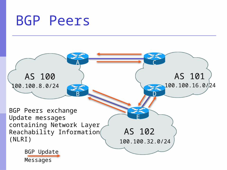
AS 100 AS 101
AS 102
A C
BGP Peers
E
B D100.100.8.0/24 100.100.16.0/24
100.100.32.0/24
BGP Peers exchange Update messages containing Network Layer Reachability Information (NLRI)
BGP UpdateMessages
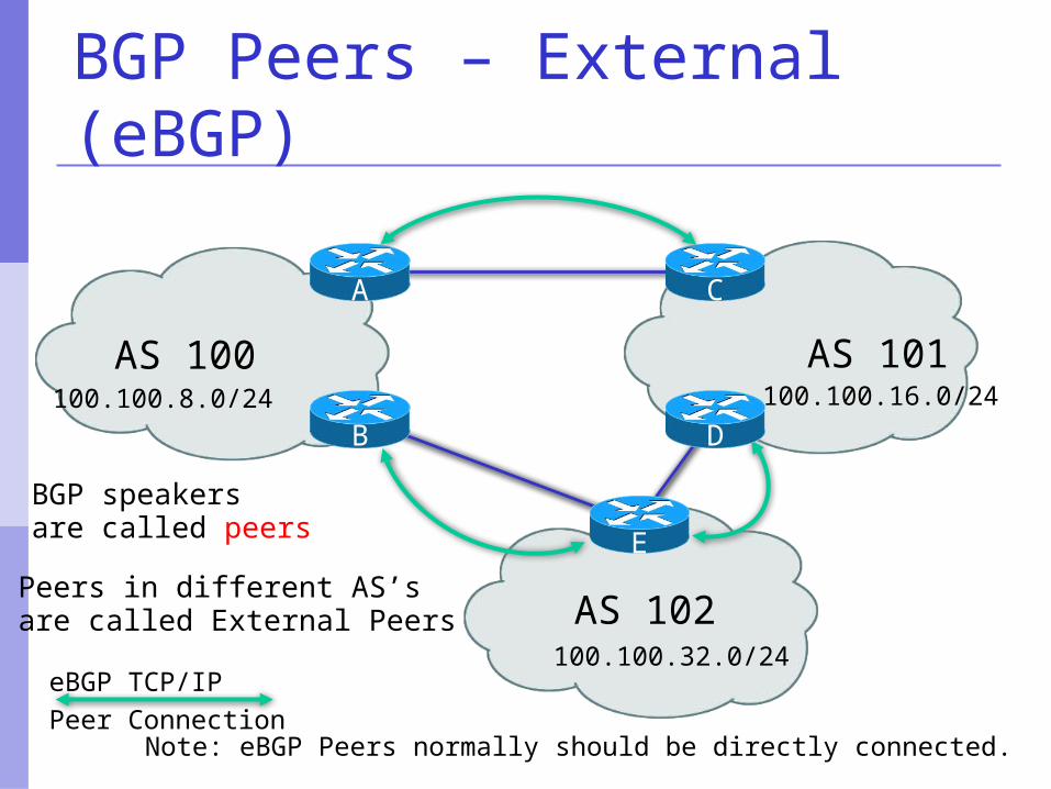
BGP Peers – External (eBGP)
AS 100 AS 101
AS 102
A C
BGP speakers are called peers
Peers in different AS’sare called External Peers
Note: eBGP Peers normally should be directly connected.
E
B D100.100.8.0/24 100.100.16.0/24
100.100.32.0/24eBGP TCP/IPPeer Connection
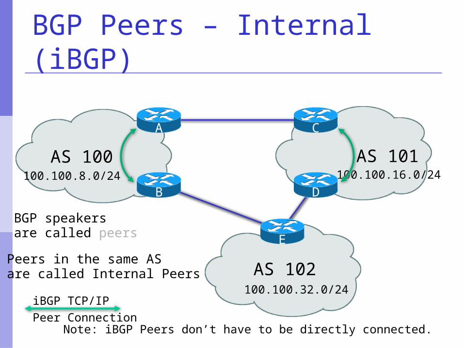
AS 100 AS 101
AS 102
A C
BGP speakers are called peers
BGP Peers – Internal (iBGP)
Peers in the same ASare called Internal Peers
Note: iBGP Peers don’t have to be directly connected.
E
B D100.100.8.0/24 100.100.16.0/24
100.100.32.0/24iBGP TCP/IPPeer Connection
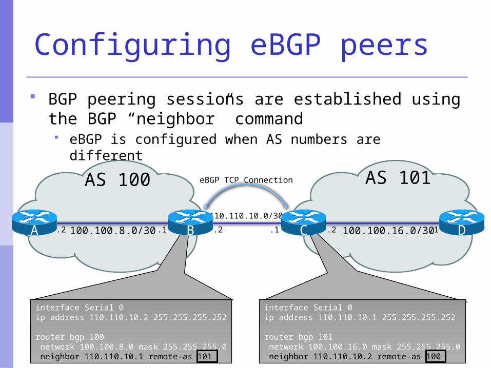
interface Serial 0ip address 110.110.10.2 255.255.255.252
router bgp 100 network 100.100.8.0 mask 255.255.255.0 neighbor 110.110.10.1 remote-as 101
interface Serial 0ip address 110.110.10.1 255.255.255.252
router bgp 101 network 100.100.16.0 mask 255.255.255.0 neighbor 110.110.10.2 remote-as 100
eBGP TCP Connection
110.110.10.0/30
B C DA
AS 100 AS 101
.2100.100.8.0/30 100.100.16.0/30.2 .1 .2 .1.1
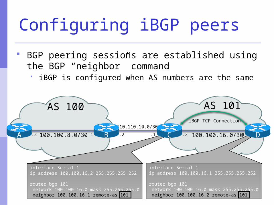
Configuring eBGP peers
BGP peering sessions are established using the BGP “neighbor” command eBGP is configured when AS numbers are different
AS 100 AS 101
110.110.10.0/30
.2
interface Serial 1ip address 100.100.16.2 255.255.255.252
router bgp 101 network 100.100.16.0 mask 255.255.255.0 neighbor 100.100.16.1 remote-as 101
B
interface Serial 1ip address 100.100.16.1 255.255.255.252
router bgp 101 network 100.100.16.0 mask 255.255.255.0 neighbor 100.100.16.2 remote-as 101
C
iBGP TCP Connection
D100.100.8.0/30 100.100.16.0/30A .2 .1 .2 .1.1
Configuring iBGP peers
BGP peering sessions are established using the BGP “neighbor” command iBGP is configured when AS numbers are the same
iBGP TCP/IPPeer Connection
AS 100
AB
C
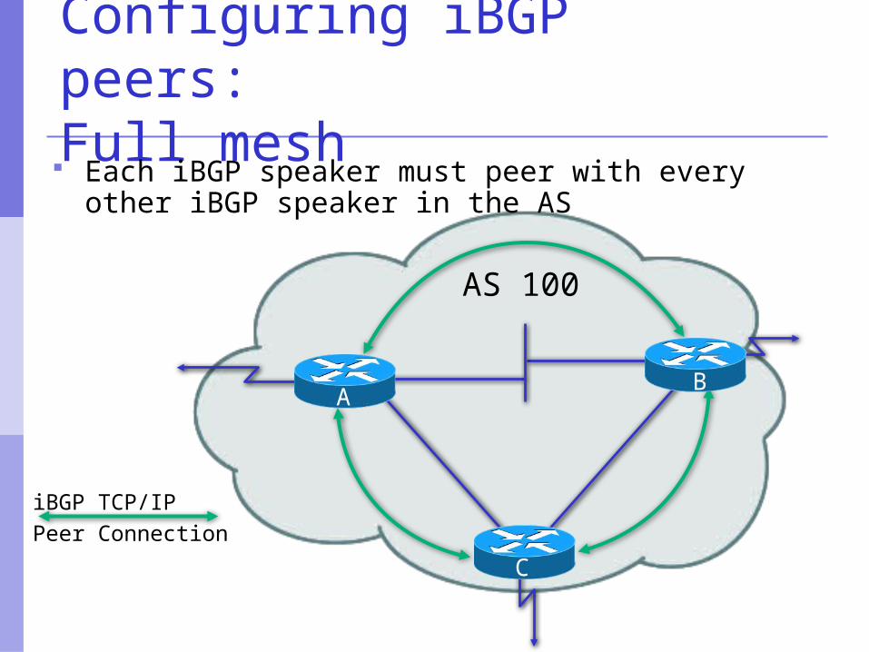
Configuring iBGP peers:Full mesh Each iBGP speaker must peer with every other
iBGP speaker in the AS
iBGP TCP/IPPeer Connection
AS 100
AB
C
105.10.7.1105.10.7.2
105.10.7.3
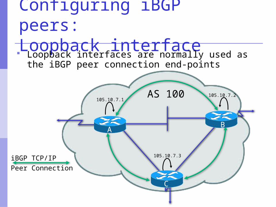
Configuring iBGP peers:Loopback interface Loopback interfaces are normally used as the
iBGP peer connection end-points
Configuring iBGP peers
AS 100
AB
C
105.10.7.1105.10.7.2
105.10.7.3
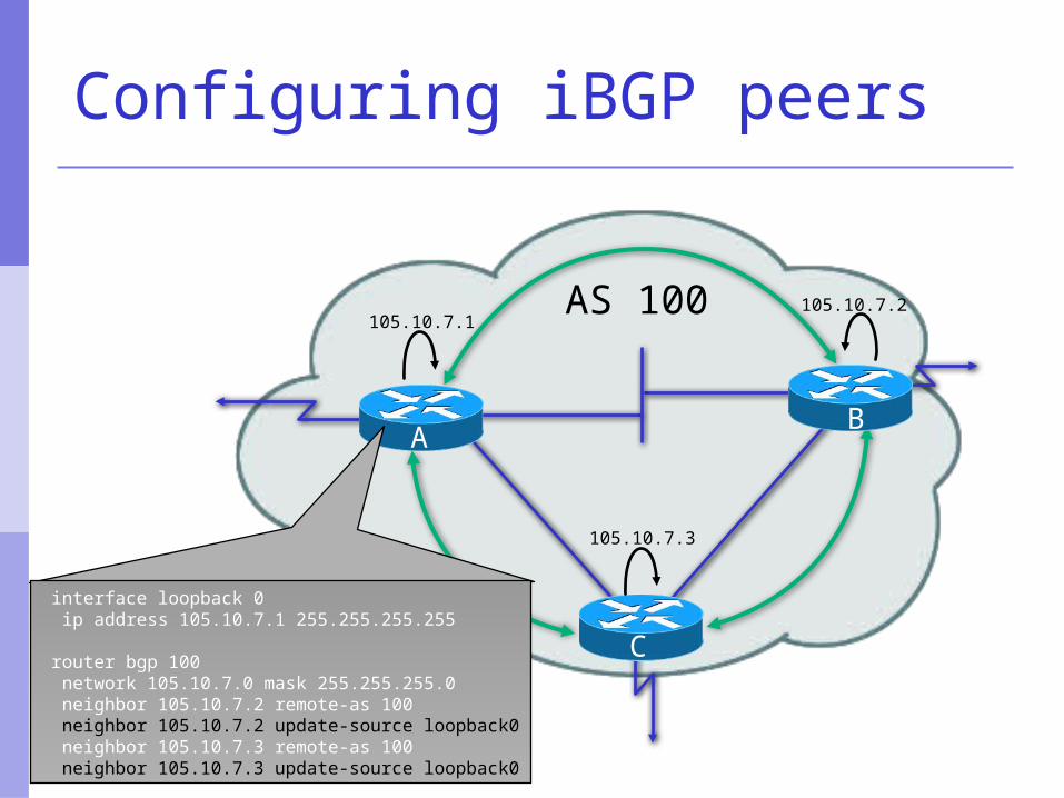
interface loopback 0 ip address 105.10.7.1 255.255.255.255
router bgp 100 network 105.10.7.0 mask 255.255.255.0 neighbor 105.10.7.2 remote-as 100 neighbor 105.10.7.2 update-source loopback0 neighbor 105.10.7.3 remote-as 100 neighbor 105.10.7.3 update-source loopback0

Configuring iBGP peers
AS 100
AB
C
105.10.7.1105.10.7.2
105.10.7.3
interface loopback 0 ip address 105.10.7.2 255.255.255.255
router bgp 100 network 105.10.7.0 mask 255.255.255.0 neighbor 105.10.7.1 remote-as 100 neighbor 105.10.7.1 update-source loopback0 neighbor 105.10.7.3 remote-as 100 neighbor 105.10.7.3 update-source loopback0
iBGP TCP/IPPeer Connection
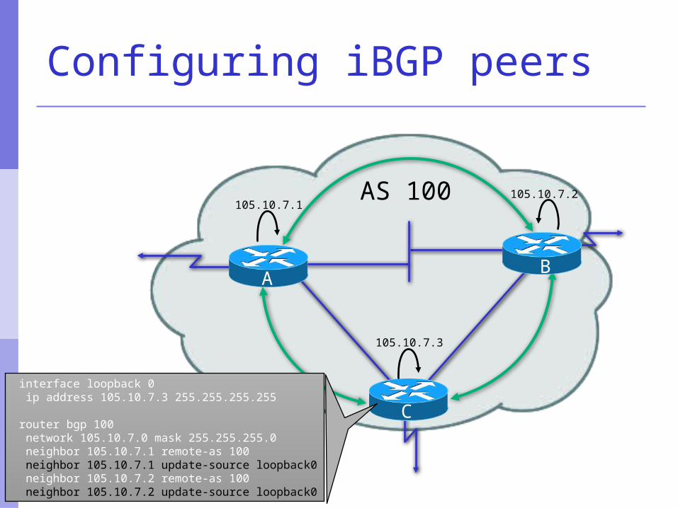
Configuring iBGP peers
AS 100
AB
C
105.10.7.1105.10.7.2
105.10.7.3
interface loopback 0 ip address 105.10.7.3 255.255.255.255
router bgp 100 network 105.10.7.0 mask 255.255.255.0 neighbor 105.10.7.1 remote-as 100 neighbor 105.10.7.1 update-source loopback0 neighbor 105.10.7.2 remote-as 100 neighbor 105.10.7.2 update-source loopback0
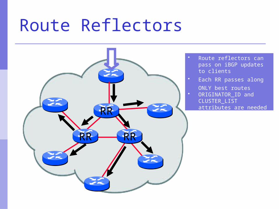
Route Reflectors
• Route reflectors can pass on iBGP updates to clients
• Each RR passes along
ONLY best routes • ORIGINATOR_ID and
CLUSTER_LIST attributes are needed to avoid loops
RR RR
RR
BGP Part III
BGP Protocol – A little more detail
BGP Updates — NLRI
Network Layer Reachability Information Used to advertise feasible routes Composed of:
Network Prefix Mask Length
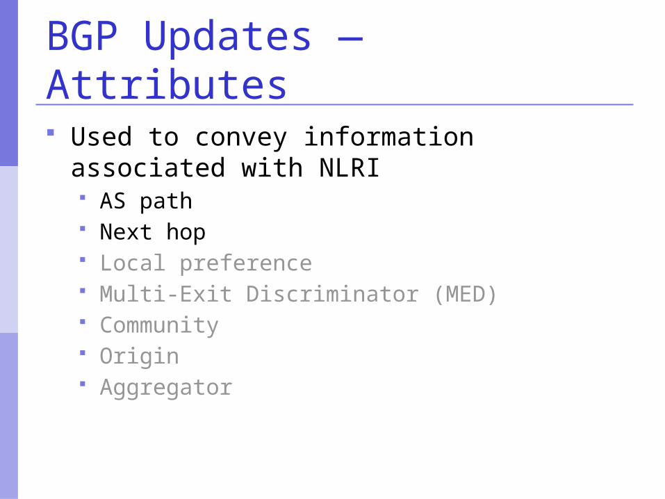
BGP Updates — Attributes
Used to convey information associated with NLRI AS path Next hop Local preference Multi-Exit Discriminator (MED) Community Origin Aggregator
AS 100
AS 300
AS 200
AS 500
AS 400
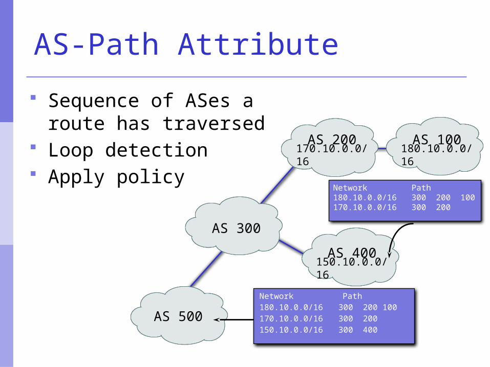
170.10.0.0/16 180.10.0.0/16
150.10.0.0/16
Network Path180.10.0.0/16 300 200 100170.10.0.0/16 300 200150.10.0.0/16 300 400
Network Path180.10.0.0/16 300 200 100170.10.0.0/16 300 200
AS-Path Attribute
Sequence of ASes a route has traversed
Loop detection Apply policy
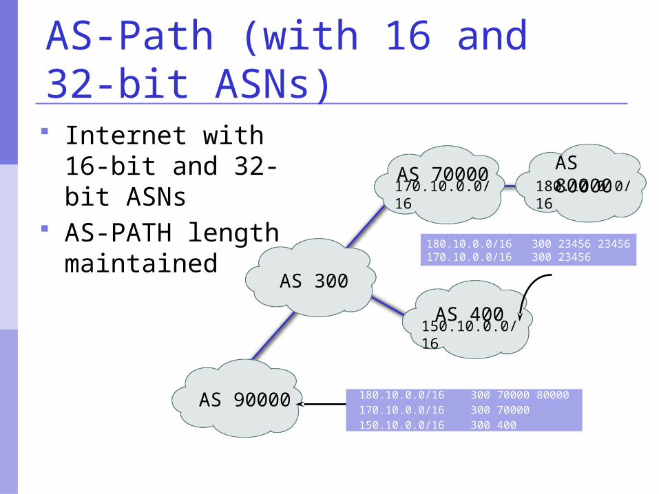
AS-Path (with 16 and 32-bit ASNs) Internet with 16-bit
and 32-bit ASNs AS-PATH length
maintained 180.10.0.0/16 300 23456 23456170.10.0.0/16 300 23456
AS 80000
AS 300
AS 70000
AS 90000
AS 400
170.10.0.0/16 180.10.0.0/16
150.10.0.0/16
180.10.0.0/16 300 70000 80000170.10.0.0/16 300 70000150.10.0.0/16 300 400
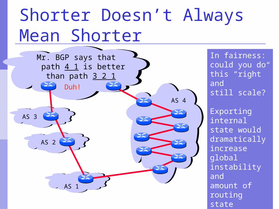
Shorter Doesn’t Always Mean Shorter
In fairness: could you do this “right” and still scale?
Exporting internalstate would dramatically increase global instability and amount of routingstate
AS 4
AS 3
AS 2
AS 1
Mr. BGP says that path 4 1 is better than path 3 2 1
Duh!
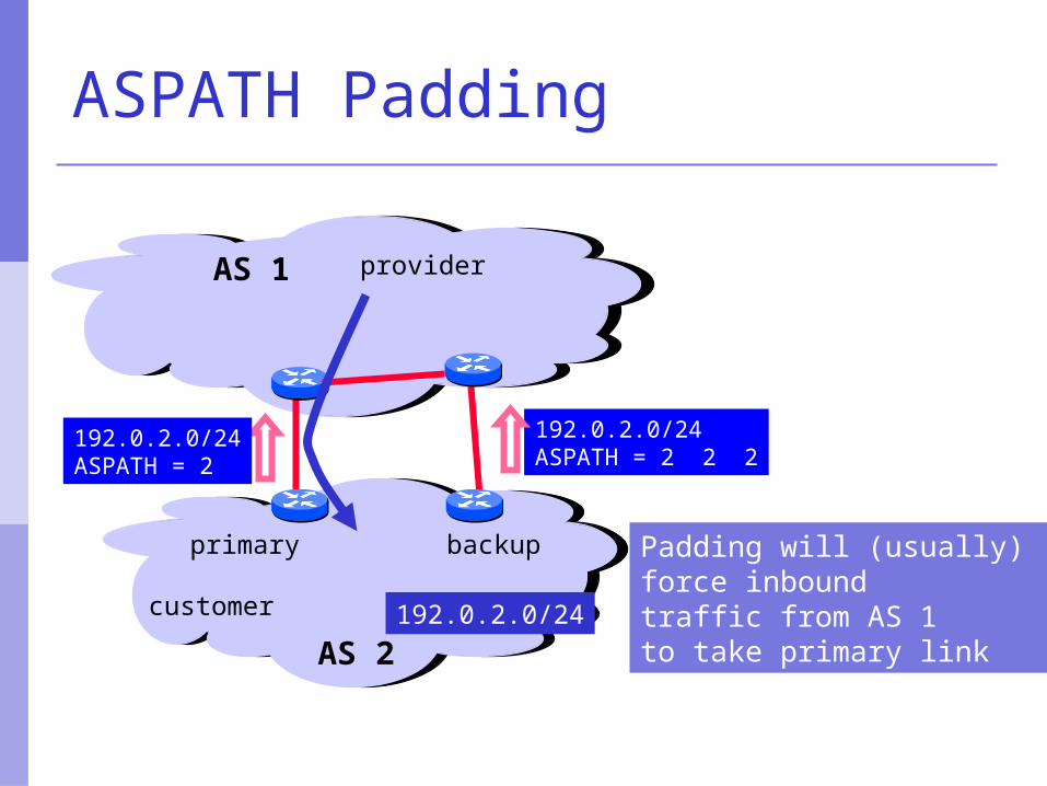
ASPATH Padding
Padding will (usually) force inbound traffic from AS 1to take primary link
AS 1
192.0.2.0/24ASPATH = 2 2 2
customer
AS 2
provider
192.0.2.0/24
backupprimary
192.0.2.0/24ASPATH = 2
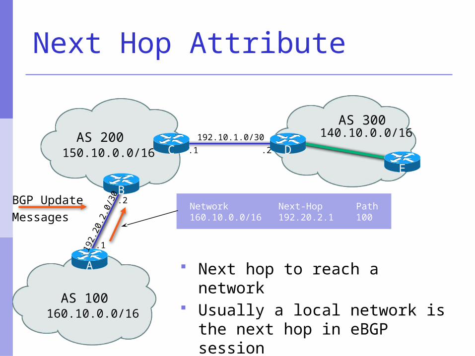
160.10.0.0/16
150.10.0.0/16192.10.1.0/30
.2
AS 100
AS 200
Network Next-Hop Path160.10.0.0/16 192.20.2.1 100
C .1
B
A
.1
.2
192.
20.2
.0/3
0AS 300
E
D140.10.0.0/16
BGP UpdateMessages
Next Hop Attribute
Next hop to reach a network Usually a local network is the
next hop in eBGP session
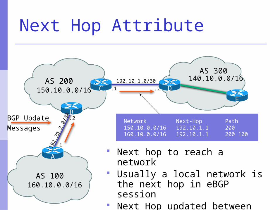
160.10.0.0/16
150.10.0.0/16192.10.1.0/30
.2
AS 100
AS 200C .1
B
A
.1
.2
192.
20.2
.0/3
0AS 300
E
D140.10.0.0/16
BGP UpdateMessages
Network Next-Hop Path150.10.0.0/16 192.10.1.1 200160.10.0.0/16 192.10.1.1 200 100
Next Hop Attribute
Next hop to reach a network Usually a local network is the
next hop in eBGP session Next Hop updated between
eBGP Peers
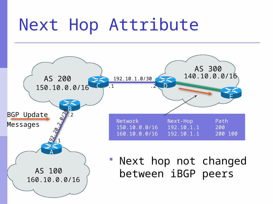
160.10.0.0/16
150.10.0.0/16192.10.1.0/30
.2
AS 100
AS 200C .1
B
A
.1
.2
192.
20.2
.0/3
0AS 300
E
D140.10.0.0/16
BGP UpdateMessages Network Next-Hop Path
150.10.0.0/16 192.10.1.1 200160.10.0.0/16 192.10.1.1 200 100
Next Hop Attribute
Next hop not changedbetween iBGP peers
Next Hop Attribute (more)
IGP is used to carry route to next hops Recursive route look-up
BGP looks into IGP to find out next hop information
BGP is not permitted to use a BGP route as the next hop
Unlinks BGP from actual physical topology
Allows IGP to make intelligent forwarding decision
Next Hop Best Practice
Cisco IOS default is for external next-hop to be propagated unchanged to iBGP peers This means that IGP has to carry external next-
hops Forgetting means external network is invisible With many eBGP peers, it is extra load on IGP
ISP best practice is to change external next-hop to be that of the local router neighbor x.x.x.x next-hop-self
Community Attribute
32-bit number Conventionally written as two 16-bit
numbers separated by colon First half is usually an AS number ISP determines the meaning (if any) of the
second half Carried in BGP protocol messages
Used by administratively-defined filters Not directly used by BGP protocol (except
for a few “well known” communities)
BGP Updates:Withdrawn Routes Used to “withdraw” network reachability Each withdrawn route is composed of:
Network Prefix Mask Length
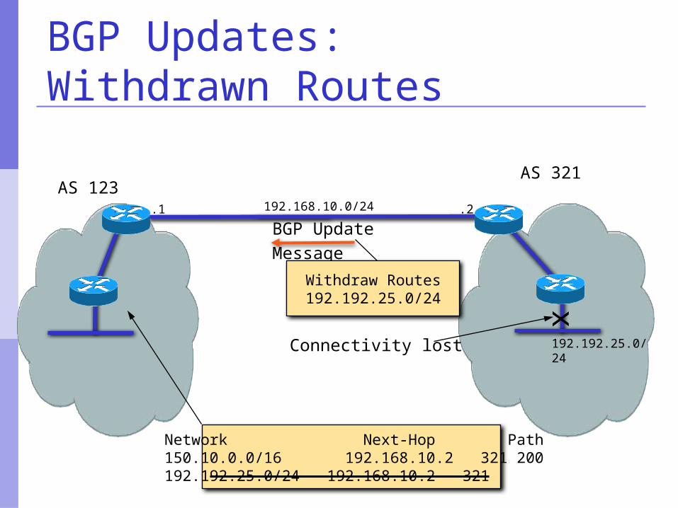
BGP Updates:Withdrawn Routes
AS 321AS 123
192.168.10.0/24
192.192.25.0/24
.1 .2
x
Connectivity lost
BGP UpdateMessage
Withdraw Routes192.192.25.0/24
Network Next-Hop Path150.10.0.0/16 192.168.10.2 321 200192.192.25.0/24 192.168.10.2 321
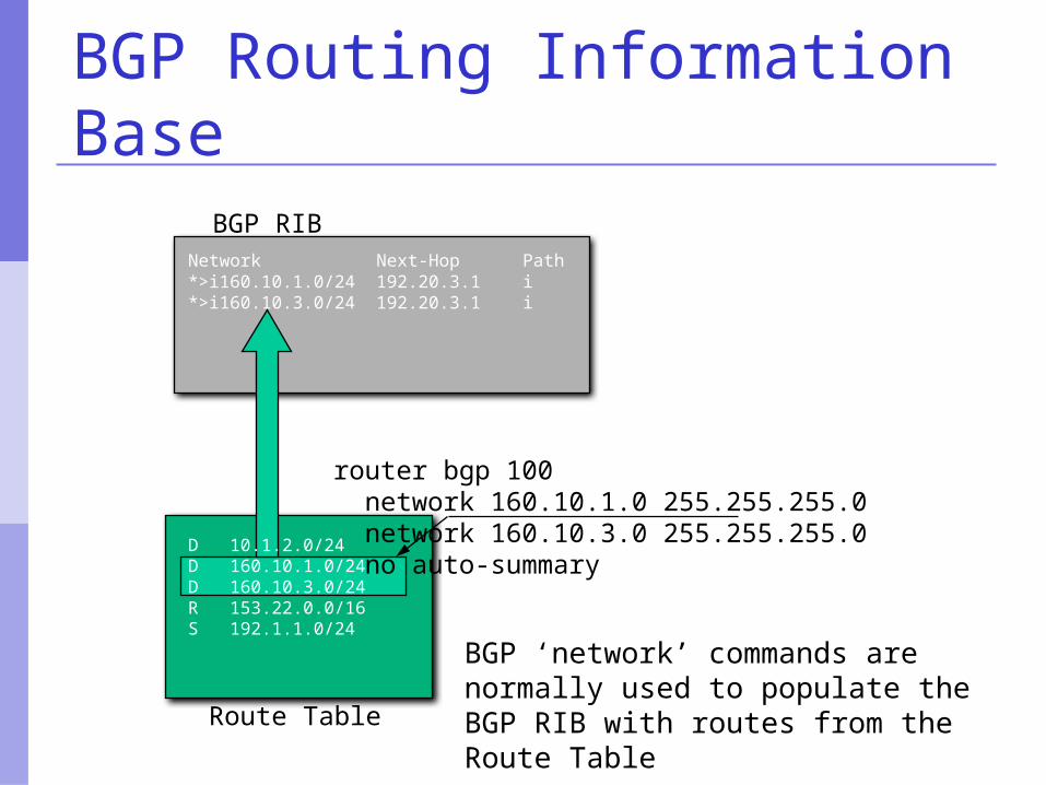
BGP Routing Information Base
BGP RIB
D 10.1.2.0/24D 160.10.1.0/24D 160.10.3.0/24R 153.22.0.0/16S 192.1.1.0/24
Network Next-Hop Path
router bgp 100 network 160.10.1.0 255.255.255.0 network 160.10.3.0 255.255.255.0 no auto-summary
Route Table
*>i160.10.1.0/24 192.20.3.1 i*>i160.10.3.0/24 192.20.3.1 i
BGP ‘network’ commands are normally used to populate the BGP RIB with routes from the Route Table
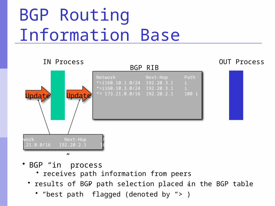
BGP Routing Information Base
BGP RIBIN Process
Network Next-Hop Path173.21.0.0/16 192.20.2.1 100
Update * 173.21.0.0/16 192.20.2.1 100 i
• BGP “in” process• receives path information from peers• results of BGP path selection placed in the BGP table• “best path” flagged (denoted by “>”)
Update
Network Next-Hop Path*>i160.10.1.0/24 192.20.3.1 i*>i160.10.3.0/24 192.20.3.1 i
OUT Process
>
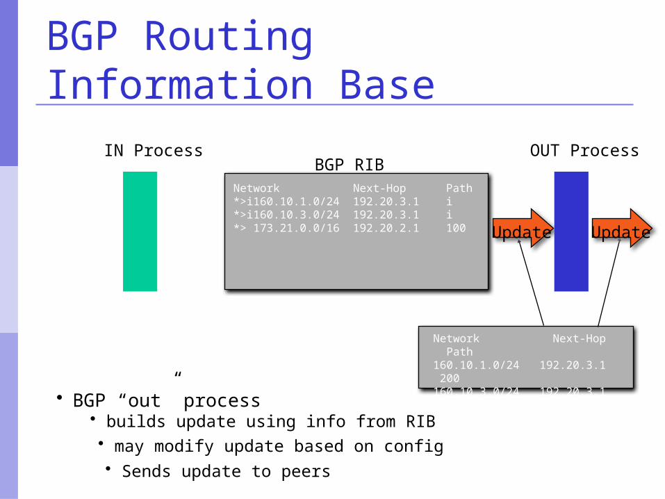
BGP Routing Information Base
OUT Process
Network Next-Hop Path160.10.1.0/24 192.20.3.1 200160.10.3.0/24 192.20.3.1 200173.21.0.0/16 192.20.2.1 200 100
BGP RIB
> 173.21.0.0/16 192.20.2.1 100
Network Next-Hop Path*>i160.10.1.0/24 192.20.3.1 i*>i160.10.3.0/24 192.20.3.1 i*
IN Process
Update Update
• BGP “out” process• builds update using info from RIB• may modify update based on config• Sends update to peers
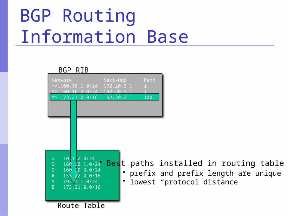
BGP Routing Information Base
BGP RIB
D 10.1.2.0/24D 160.10.1.0/24D 160.10.3.0/24R 153.22.0.0/16S 192.1.1.0/24
Network Next-Hop Path*>i160.10.1.0/24 192.20.3.1 i*>i160.10.3.0/24 192.20.3.1 i*> 173.21.0.0/16 192.20.2.1 100
• Best paths installed in routing table if:
B 173.21.0.0/16
Route Table
• prefix and prefix length are unique• lowest “protocol distance”
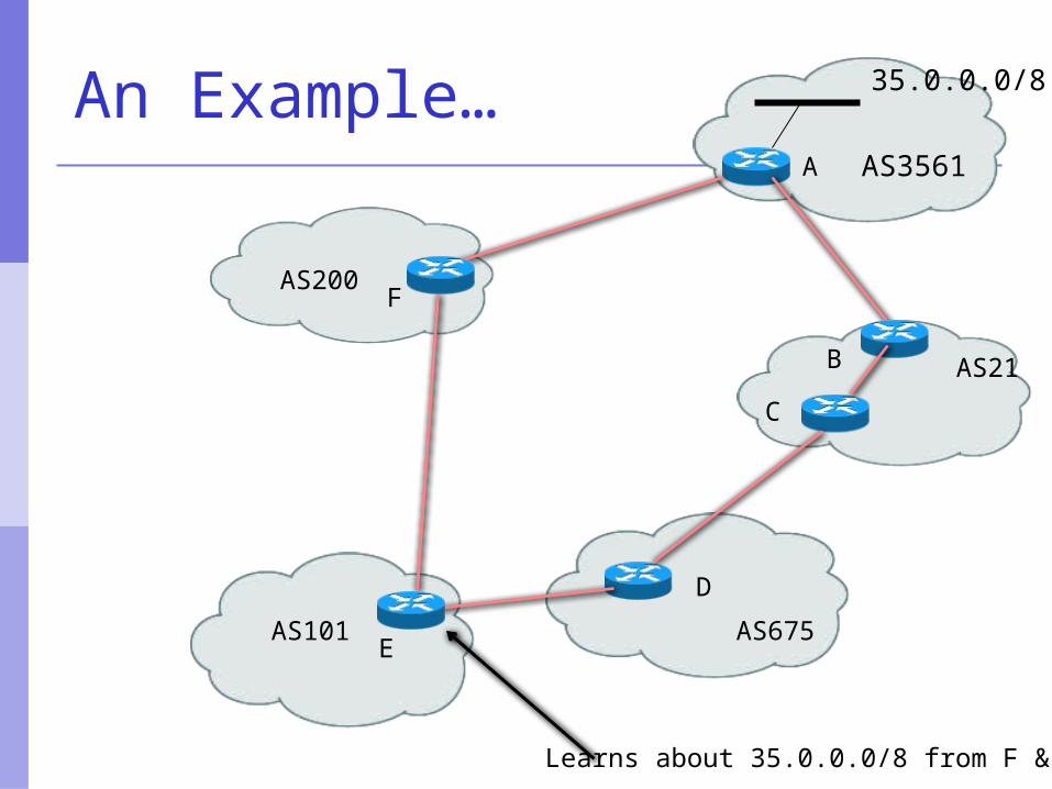
An Example…
Learns about 35.0.0.0/8 from F & D
AS3561
B
E
C
D
F
A
AS200
AS101
AS21
AS675
35.0.0.0/8
BGP Part IV
Routing PolicyFiltering
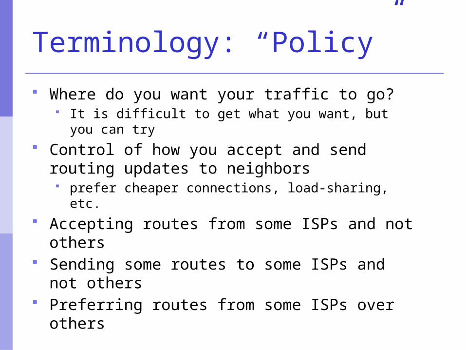
Terminology: “Policy”
Where do you want your traffic to go? It is difficult to get what you want, but you can try
Control of how you accept and send routing updates to neighbors prefer cheaper connections, load-sharing, etc.
Accepting routes from some ISPs and not others
Sending some routes to some ISPs and not others
Preferring routes from some ISPs over others
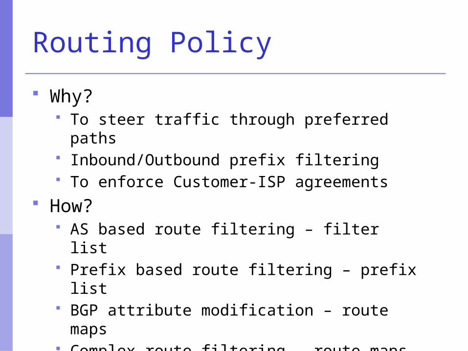
Routing Policy
Why? To steer traffic through preferred paths Inbound/Outbound prefix filtering To enforce Customer-ISP agreements
How? AS based route filtering – filter list Prefix based route filtering – prefix list BGP attribute modification – route maps Complex route filtering – route maps
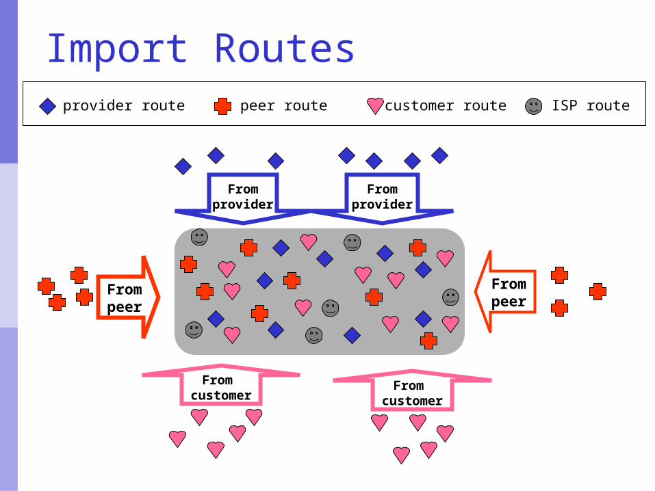
Import Routes
Frompeer
Frompeer
Fromprovider
Fromprovider
From customer
From customer
provider route customer routepeer route ISP route

Export Routes
Topeer
Topeer
Tocustomer
Tocustomer
Toprovider
From provider
provider route customer routepeer route ISP route
filtersblock
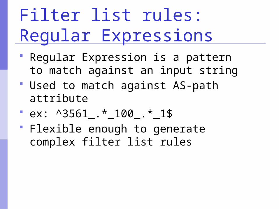
Filter list rules: Regular Expressions Regular Expression is a pattern to
match against an input string Used to match against AS-path attribute ex: ^3561_.*_100_.*_1$ Flexible enough to generate complex
filter list rules
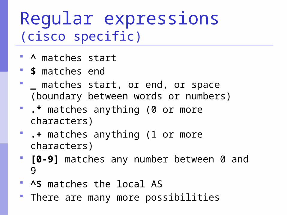
Regular expressions (cisco specific)
^ matches start $ matches end _ matches start, or end, or space (boundary
between words or numbers) .* matches anything (0 or more characters) .+ matches anything (1 or more characters) [0-9] matches any number between 0 and 9 ^$ matches the local AS There are many more possibilities
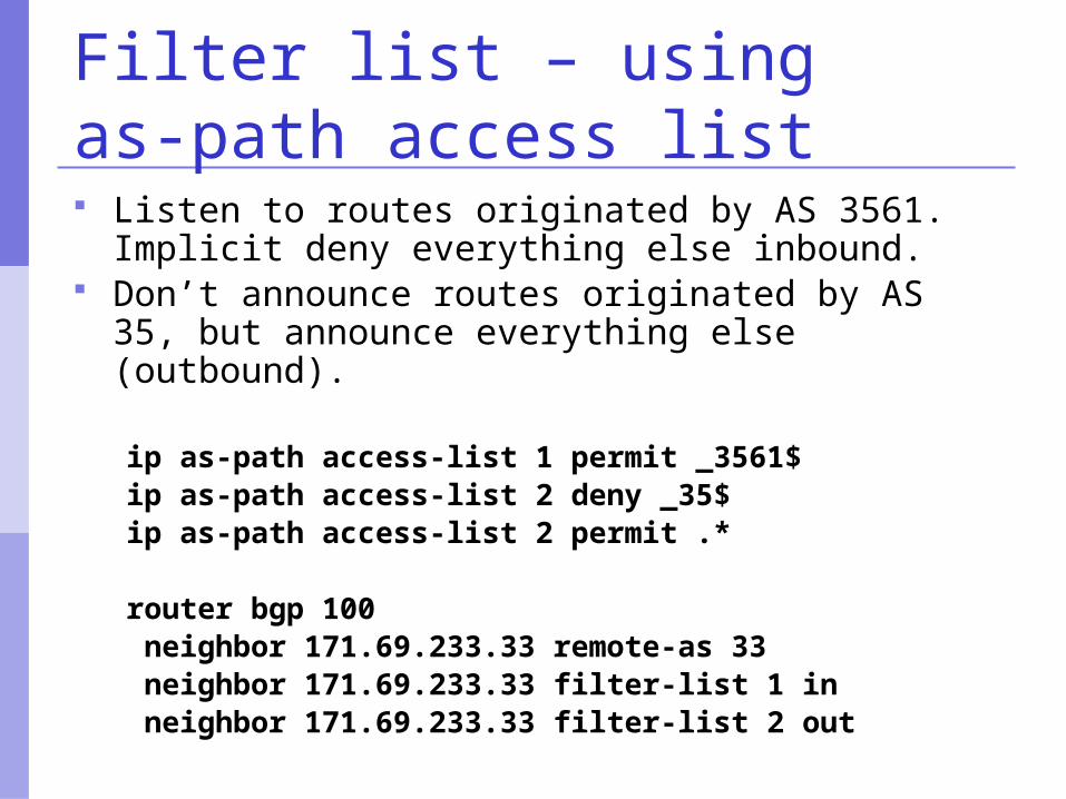
Filter list – using as-path access list Listen to routes originated by AS 3561. Implicit
deny everything else inbound. Don’t announce routes originated by AS 35,
but announce everything else (outbound).
ip as-path access-list 1 permit _3561$ip as-path access-list 2 deny _35$ip as-path access-list 2 permit .*
router bgp 100 neighbor 171.69.233.33 remote-as 33 neighbor 171.69.233.33 filter-list 1 in neighbor 171.69.233.33 filter-list 2 out
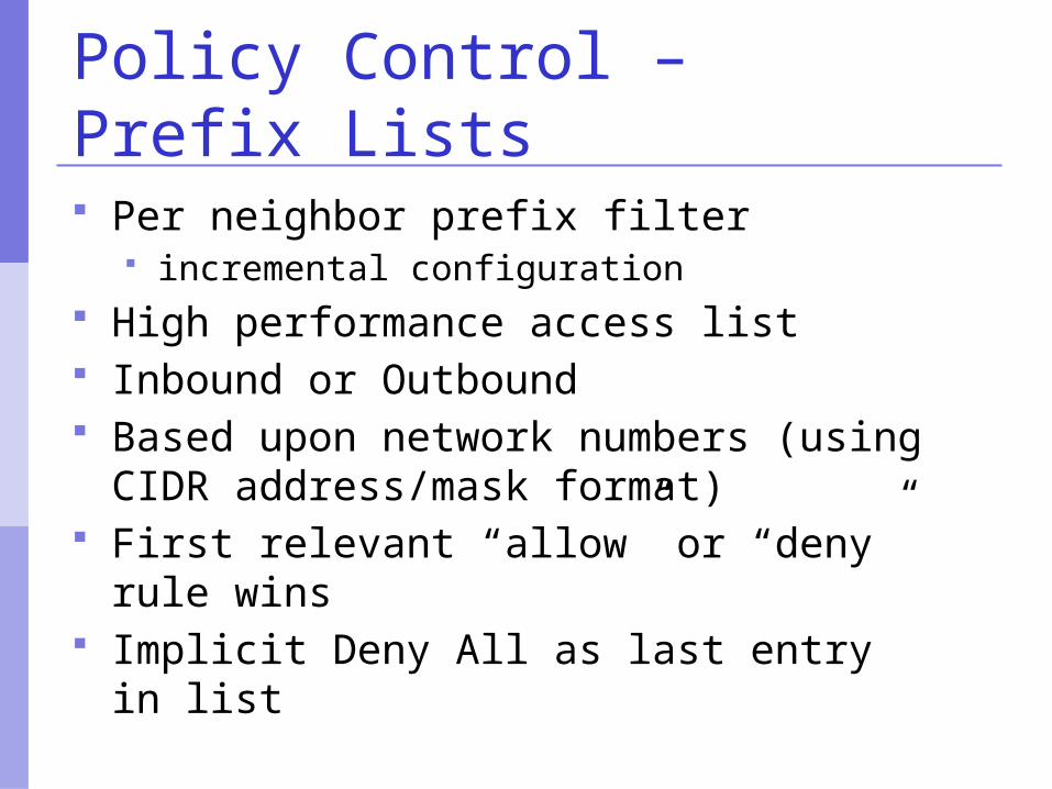
Policy Control – Prefix Lists
Per neighbor prefix filter incremental configuration
High performance access list Inbound or Outbound Based upon network numbers (using
CIDR address/mask format) First relevant “allow” or “deny” rule
wins Implicit Deny All as last entry in list
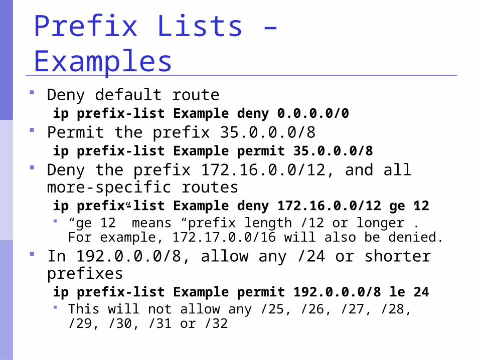
Prefix Lists – Examples
Deny default routeip prefix-list Example deny 0.0.0.0/0
Permit the prefix 35.0.0.0/8ip prefix-list Example permit 35.0.0.0/8
Deny the prefix 172.16.0.0/12, and all more-specific routesip prefix-list Example deny 172.16.0.0/12 ge 12 “ge 12” means “prefix length /12 or longer”. For
example, 172.17.0.0/16 will also be denied. In 192.0.0.0/8, allow any /24 or shorter prefixes
ip prefix-list Example permit 192.0.0.0/8 le 24 This will not allow any /25, /26, /27, /28, /29, /30, /31
or /32
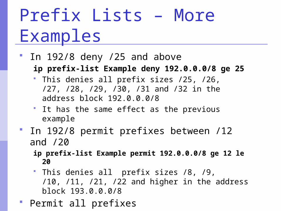
Prefix Lists – More Examples In 192/8 deny /25 and above
ip prefix-list Example deny 192.0.0.0/8 ge 25 This denies all prefix sizes /25, /26, /27, /28, /29,
/30, /31 and /32 in the address block 192.0.0.0/8 It has the same effect as the previous example
In 192/8 permit prefixes between /12 and /20ip prefix-list Example permit 192.0.0.0/8 ge 12 le
20 This denies all prefix sizes /8, /9, /10, /11, /21, /22
and higher in the address block 193.0.0.0/8 Permit all prefixes
ip prefix-list Example 0.0.0.0/0 le 32
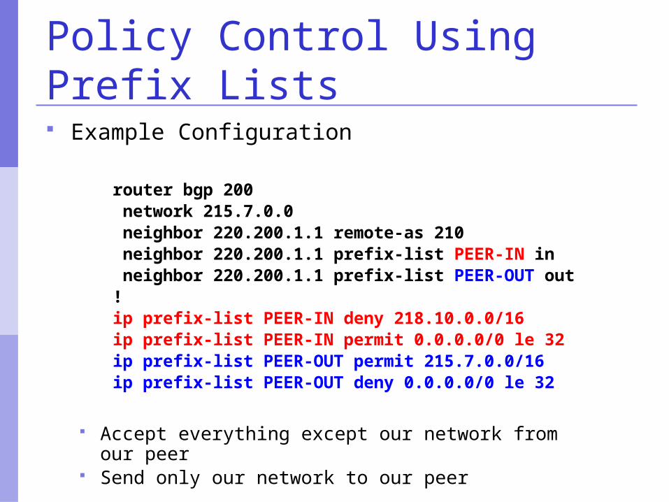
Policy Control Using Prefix Lists Example Configuration
router bgp 200 network 215.7.0.0 neighbor 220.200.1.1 remote-as 210 neighbor 220.200.1.1 prefix-list PEER-IN in neighbor 220.200.1.1 prefix-list PEER-OUT out!ip prefix-list PEER-IN deny 218.10.0.0/16ip prefix-list PEER-IN permit 0.0.0.0/0 le 32ip prefix-list PEER-OUT permit 215.7.0.0/16ip prefix-list PEER-OUT deny 0.0.0.0/0 le 32
Accept everything except our network from our peer Send only our network to our peer
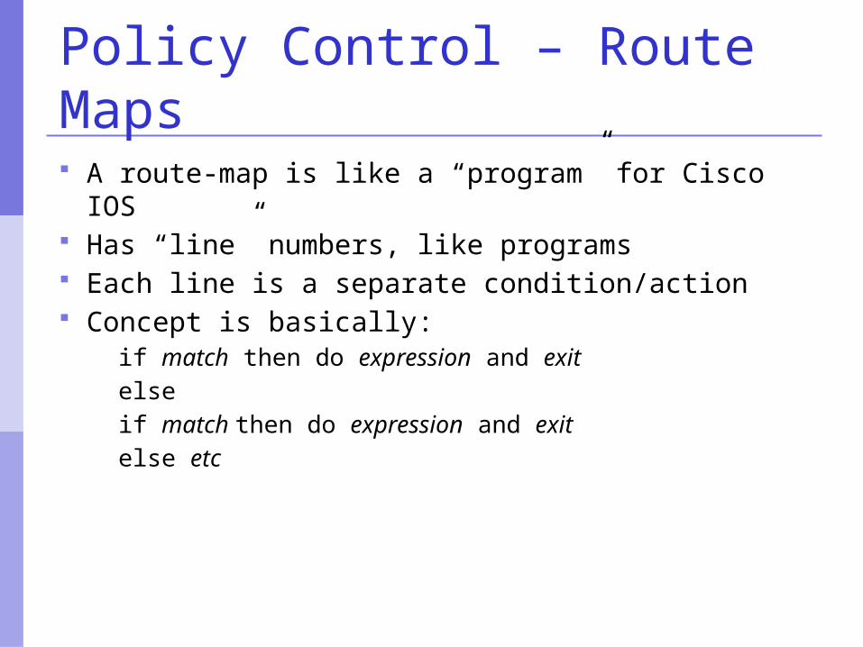
Policy Control – Route Maps A route-map is like a “program” for Cisco IOS Has “line” numbers, like programs Each line is a separate condition/action Concept is basically:
if match then do expression and exitelseif match then do expression and exitelse etc

Route-map match& set clauses Match Clauses
AS-path Community IP address
Set Clauses AS-path prepend Community Local-Preference MED Origin Weight Others...
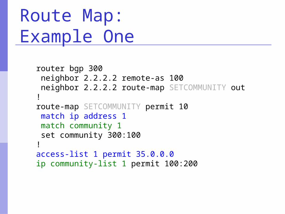
Route Map:Example One
router bgp 300 neighbor 2.2.2.2 remote-as 100 neighbor 2.2.2.2 route-map SETCOMMUNITY out!route-map SETCOMMUNITY permit 10 match ip address 1 match community 1 set community 300:100!access-list 1 permit 35.0.0.0ip community-list 1 permit 100:200
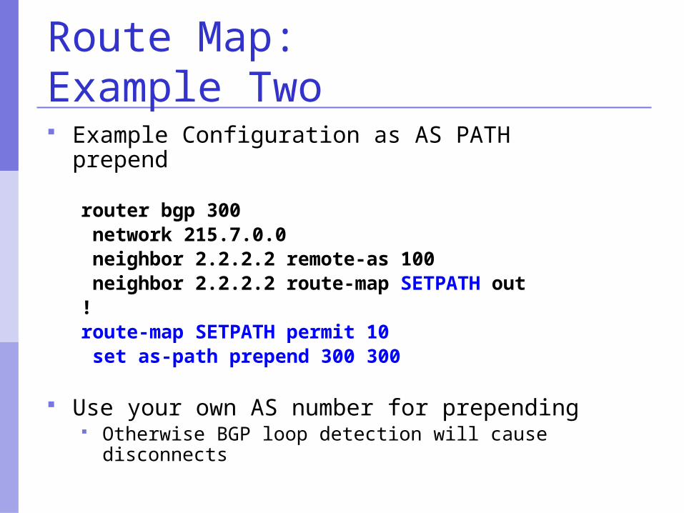
Route Map:Example Two Example Configuration as AS PATH prepend
router bgp 300 network 215.7.0.0 neighbor 2.2.2.2 remote-as 100 neighbor 2.2.2.2 route-map SETPATH out!route-map SETPATH permit 10 set as-path prepend 300 300
Use your own AS number for prepending Otherwise BGP loop detection will cause disconnects
BGP Part V
More detail than you want
BGP AttributesSynchronizationPath Selection
BGP Path Attributes: Why ?
Encoded as Type, Length & Value (TLV) Transitive/Non-Transitive attributes Some are mandatory Used in path selection To apply policy for steering traffic
BGP Attributes
Used to convey information associated with NLRI AS path Next hop Local preference Multi-Exit Discriminator (MED) Community Origin Aggregator
Local Preference
Not used by eBGP, mandatory for iBGP Default value of 100 on Cisco IOS Local to an AS Used to prefer one exit over another Path with highest local preference wins
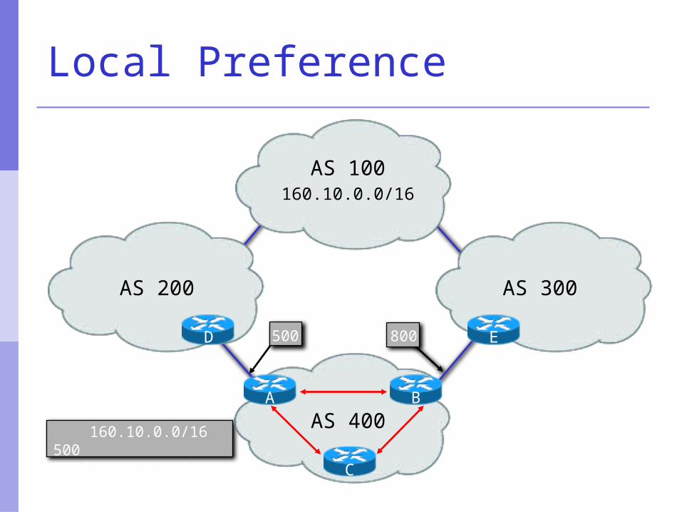
160.10.0.0/16 500> 160.10.0.0/16 800
Local Preference
AS 400
AS 200
160.10.0.0/16AS 100
AS 300
500 800 E
B
C
A
D
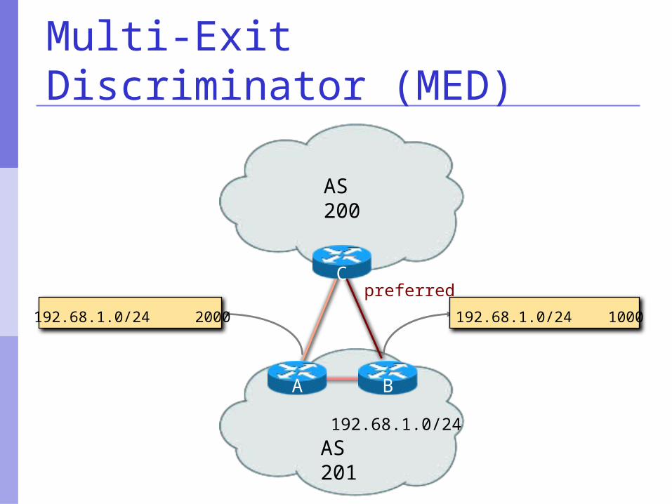
Multi-Exit Discriminator
Non-transitive Represented as a numerical value
Range 0x0 – 0xffffffff Used to convey relative preference of
entry points to an AS Comparable if the paths are from the
same AS Path with the lowest MED wins IGP metric can be conveyed as MED
AS 201
AS 200
192.68.1.0/24
C
A B
192.68.1.0/24 1000192.68.1.0/24 2000
preferred
Multi-Exit Discriminator (MED)
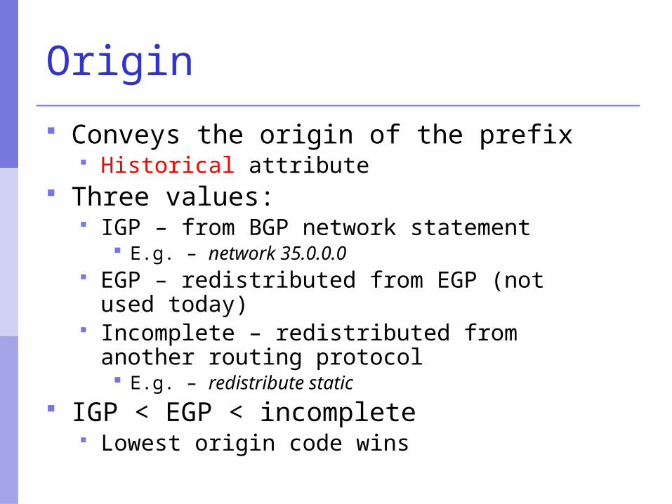
Origin
Conveys the origin of the prefix Historical attribute
Three values: IGP – from BGP network statement
E.g. – network 35.0.0.0 EGP – redistributed from EGP (not used
today) Incomplete – redistributed from another
routing protocol E.g. – redistribute static
IGP < EGP < incomplete Lowest origin code wins
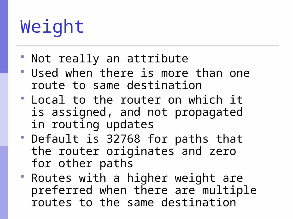
Weight
Not really an attribute Used when there is more than one route
to same destination Local to the router on which it is
assigned, and not propagated in routing updates
Default is 32768 for paths that the router originates and zero for other paths
Routes with a higher weight are preferred when there are multiple routes to the same destination
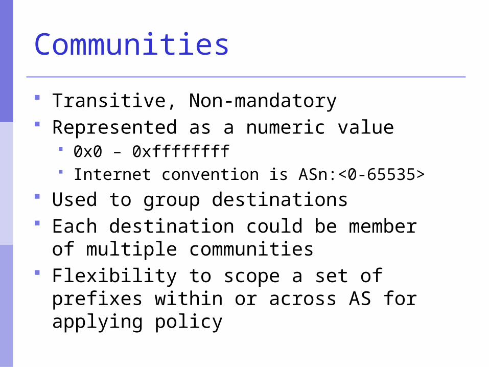
Communities
Transitive, Non-mandatory Represented as a numeric value
0x0 – 0xffffffff Internet convention is ASn:<0-65535>
Used to group destinations Each destination could be member of
multiple communities Flexibility to scope a set of prefixes
within or across AS for applying policy
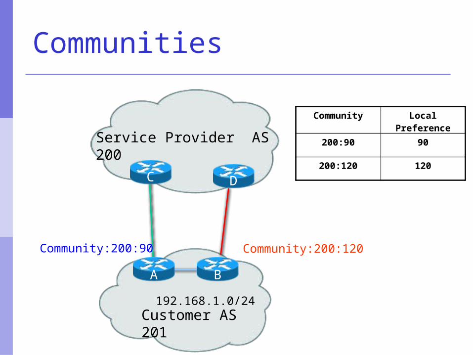
Communities
Customer AS 201
Service Provider AS 200
192.168.1.0/24
C
A B
Community:200:90 Community:200:120
D
Community Local Preference
200:90 90
200:120 120

Import Routes
Frompeer
Frompeer
Fromprovider
Fromprovider
From customer
From customer
provider route customer routepeer route ISP route
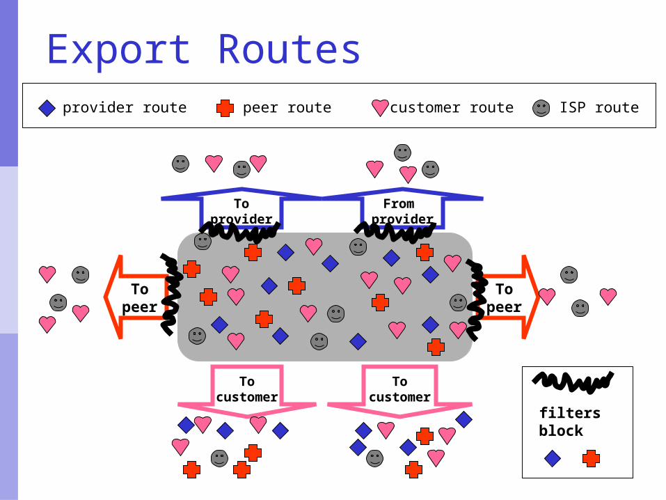
Export Routes
Topeer
Topeer
Tocustomer
Tocustomer
Toprovider
From provider
provider route customer routepeer route ISP route
filtersblock
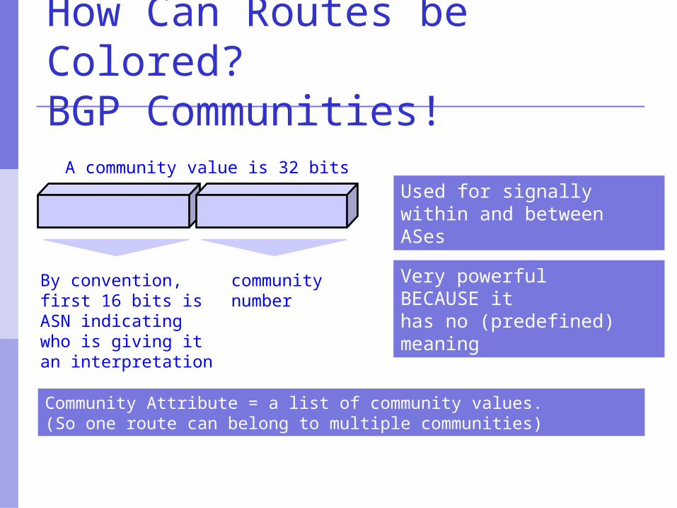
How Can Routes be Colored?BGP Communities!
A community value is 32 bits
By convention, first 16 bits is ASN indicating who is giving itan interpretation
communitynumber
Very powerful BECAUSE it has no (predefined) meaning
Community Attribute = a list of community values.(So one route can belong to multiple communities)
Used for signallywithin and betweenASes
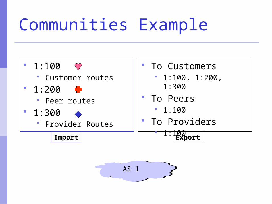
Communities Example
1:100 Customer routes
1:200 Peer routes
1:300 Provider Routes
To Customers 1:100, 1:200, 1:300
To Peers 1:100
To Providers 1:100
AS 1
Import Export
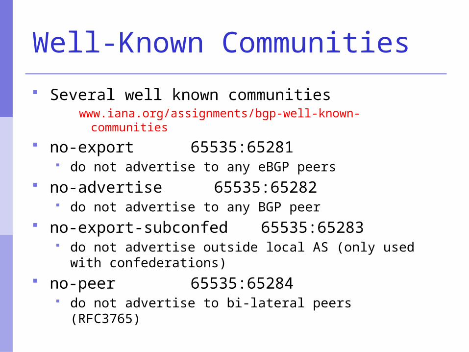
Well-Known Communities
Several well known communitieswww.iana.org/assignments/bgp-well-known-communities
no-export 65535:65281 do not advertise to any eBGP peers
no-advertise 65535:65282 do not advertise to any BGP peer
no-export-subconfed 65535:65283 do not advertise outside local AS (only used with
confederations) no-peer 65535:65284
do not advertise to bi-lateral peers (RFC3765)
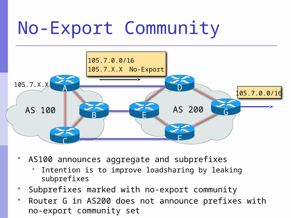
105.7.0.0/16105.7.X.X No-Export
105.7.0.0/16
AS 100 AS 200
105.7.X.X
C F
G
DA
B E
No-Export Community
AS100 announces aggregate and subprefixes Intention is to improve loadsharing by leaking subprefixes
Subprefixes marked with no-export community Router G in AS200 does not announce prefixes with no-
export community set
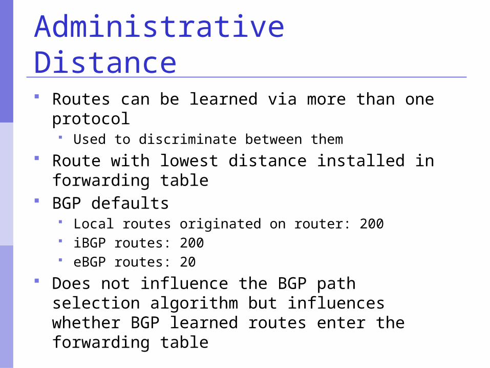
Administrative Distance
Routes can be learned via more than one protocol Used to discriminate between them
Route with lowest distance installed in forwarding table
BGP defaults Local routes originated on router: 200 iBGP routes: 200 eBGP routes: 20
Does not influence the BGP path selection algorithm but influences whether BGP learned routes enter the forwarding table
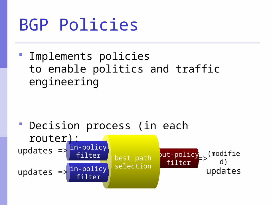
=>(modified) updates
out-policyfilter
best pathselection
in-policyfilter
updates =>
in-policyfilter
updates =>
BGP Policies
Implements policies to enable politics and traffic engineering
Decision process (in each router):
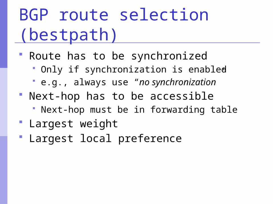
BGP route selection (bestpath) Route has to be synchronized
Only if synchronization is enabled e.g., always use “no synchronization”
Next-hop has to be accessible Next-hop must be in forwarding table
Largest weight Largest local preference
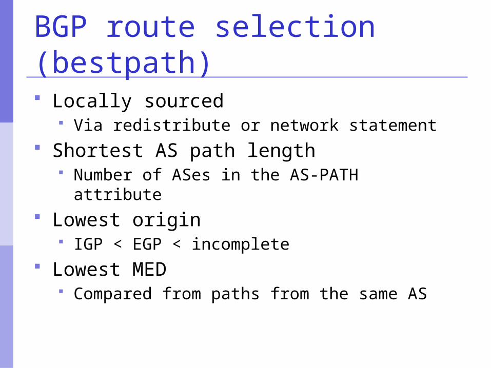
BGP route selection (bestpath) Locally sourced
Via redistribute or network statement Shortest AS path length
Number of ASes in the AS-PATH attribute Lowest origin
IGP < EGP < incomplete Lowest MED
Compared from paths from the same AS
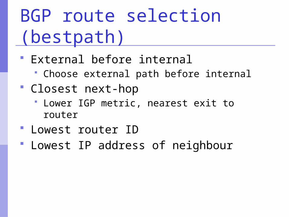
BGP route selection (bestpath) External before internal
Choose external path before internal Closest next-hop
Lower IGP metric, nearest exit to router Lowest router ID Lowest IP address of neighbour
BGP Part VI
Configuring BGPBasic commands
Getting routes into BGP
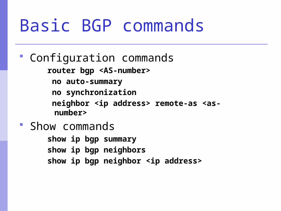
Basic BGP commands
Configuration commandsrouter bgp <AS-number> no auto-summary no synchronization neighbor <ip address> remote-as <as-number>
Show commandsshow ip bgp summaryshow ip bgp neighborsshow ip bgp neighbor <ip address>
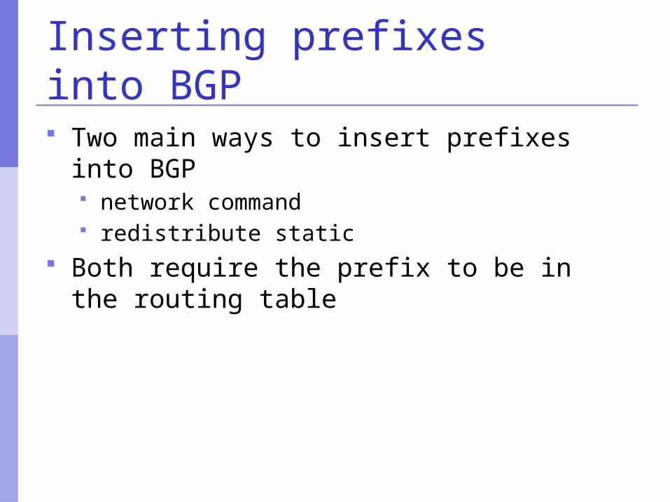
Inserting prefixes into BGP
Two main ways to insert prefixes into BGP network command redistribute static
Both require the prefix to be in the routing table
Configure iBGP
The two routers in your AS should talk iBGP to each other no filtering here use “update-source loopback 0”
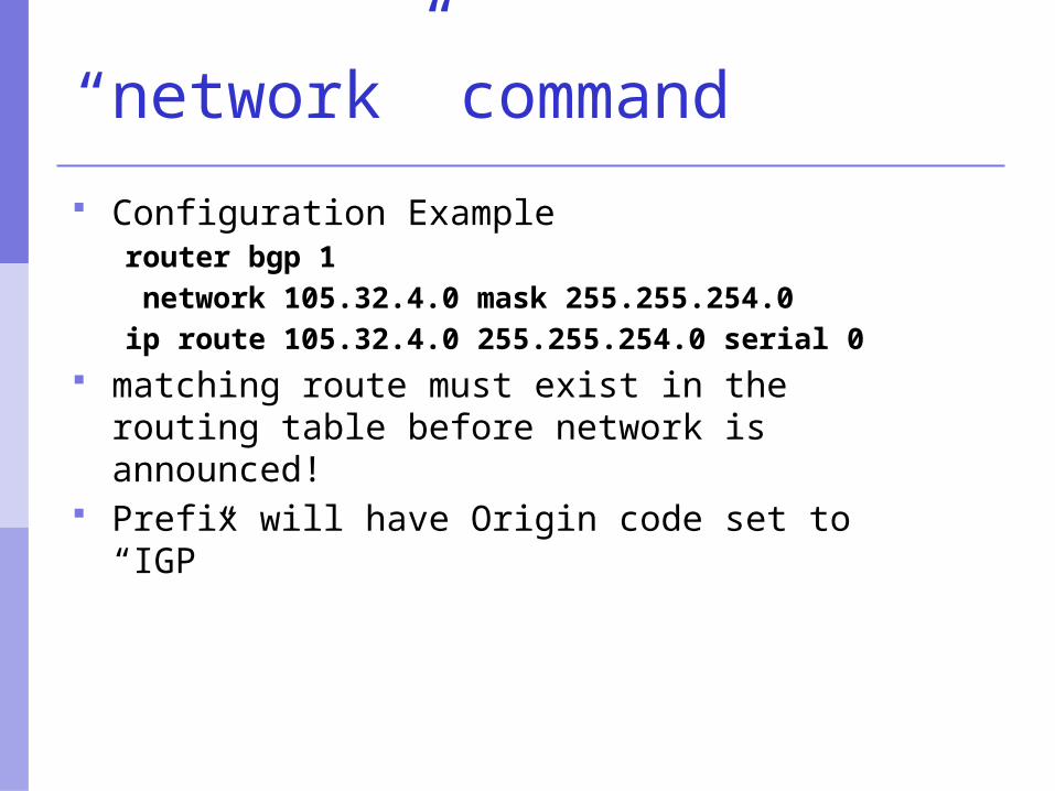
“network” command
Configuration Examplerouter bgp 1 network 105.32.4.0 mask 255.255.254.0ip route 105.32.4.0 255.255.254.0 serial 0
matching route must exist in the routing table before network is announced!
Prefix will have Origin code set to “IGP”
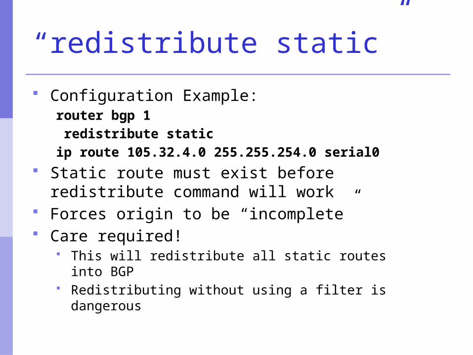
“redistribute static”
Configuration Example:router bgp 1 redistribute staticip route 105.32.4.0 255.255.254.0 serial0
Static route must exist before redistribute command will work
Forces origin to be “incomplete” Care required!
This will redistribute all static routes into BGP Redistributing without using a filter is dangerous
“redistribute static”
Care required with redistribution redistribute <routing-protocol> means
everything in the <routing-protocol> will be transferred into the current routing protocol
will not scale if uncontrolled best avoided if at all possible redistribute normally used with “route-
maps” and under tight administrative control “route-map” is used to apply policies in BGP, so is
a kind of filter
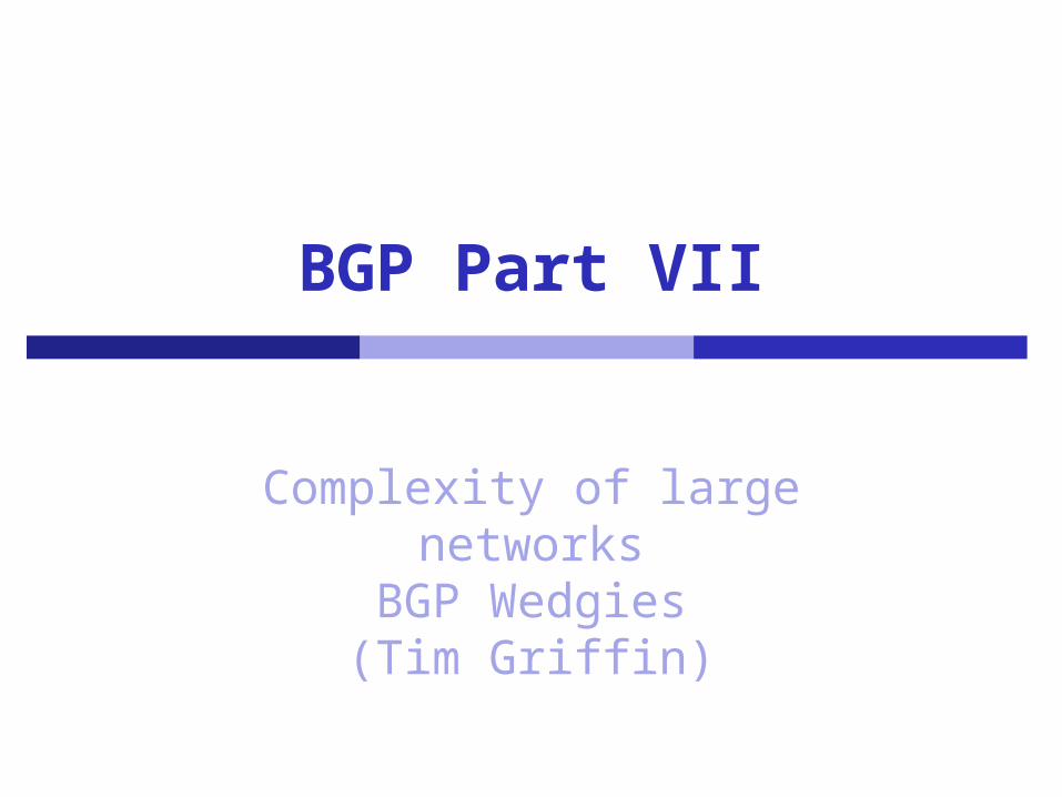
BGP Part VII
Complexity of large networksBGP Wedgies(Tim Griffin)
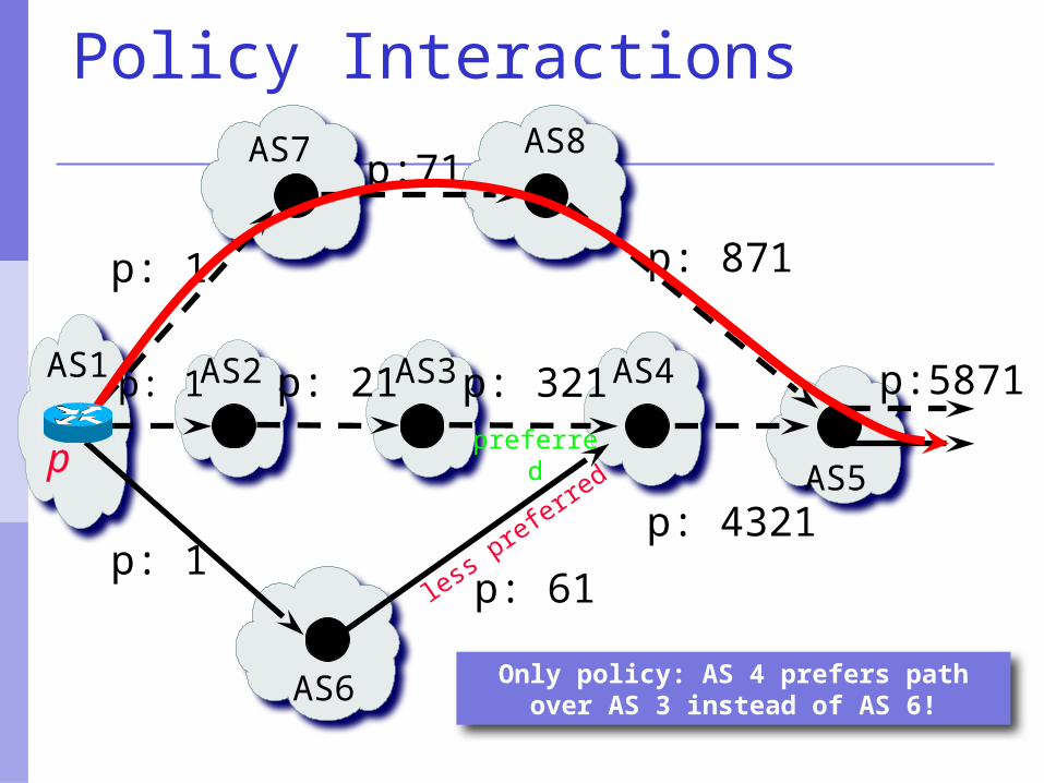
AS1
AS6
p: 1
p: 1 p: 321AS2 AS3 AS4p: 21
AS8AS7
AS5
Only policy: AS 4 prefers path over AS 3 instead of AS 6!
p:71
p: 871p: 1
p:5871
p: 4321
preferred
less preferre
d p
p: 61
Policy Interactions
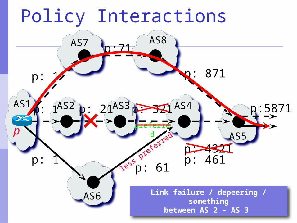
AS1
AS6
p: 1
p: 1 p: 321AS2 AS3 AS4p: 21
AS8AS7
AS5
Link failure / depeering / somethingbetween AS 2 – AS 3
p:71
p: 871p: 1
p:5871
p: 4321
preferred
less preferre
d p
p: 61p: 461
Policy Interactions
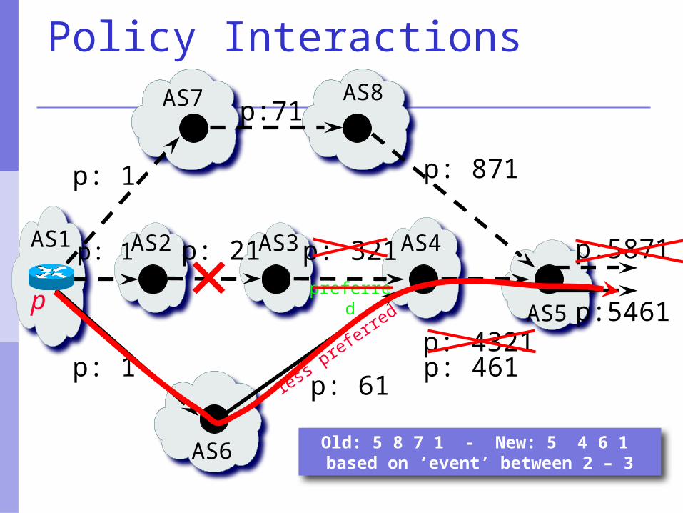
AS1
AS6
p: 1
p: 1 p: 321AS2 AS3 AS4p: 21
AS8AS7
AS5
Old: 5 8 7 1 - New: 5 4 6 1 based on ‘event’ between 2 – 3
p:71
p: 871p: 1
p:5871
p: 4321
preferred
less preferre
d p
p: 61p: 461
p:5461
Policy Interactions
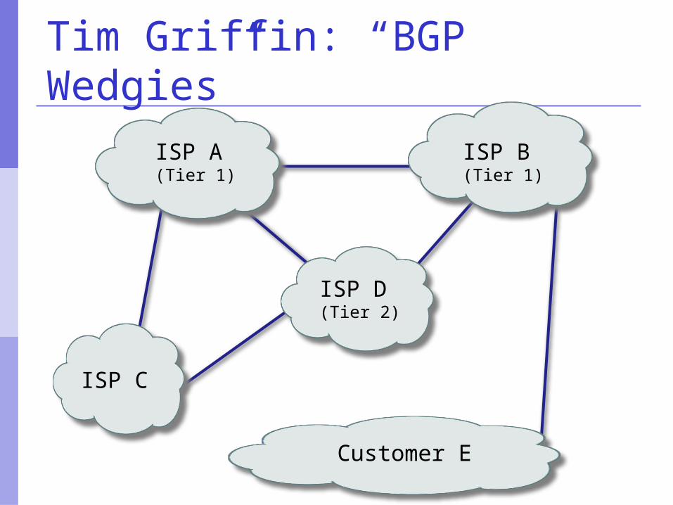
Customer E
ISP A (Tier 1)
ISP C
ISP D (Tier 2)
ISP B (Tier 1)
Tim Griffin: “BGP Wedgies”
primary link
backup link
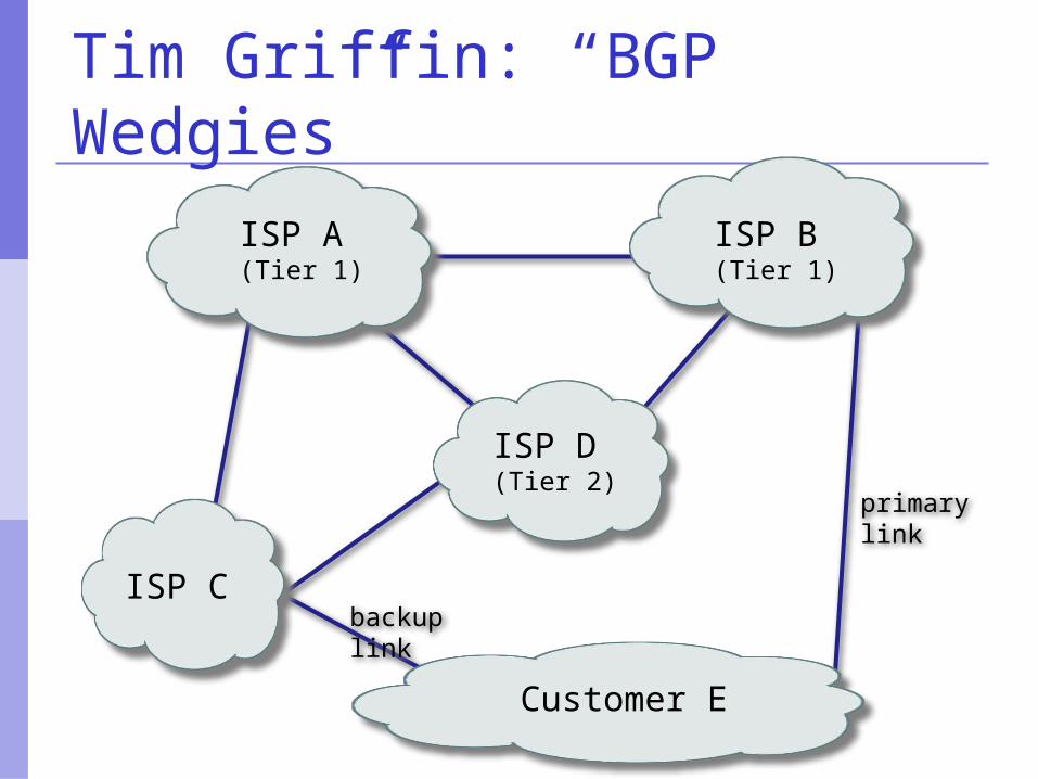
Customer E
ISP A (Tier 1)
ISP C
ISP D (Tier 2)
ISP B (Tier 1)
Tim Griffin: “BGP Wedgies”
primary link
backup link
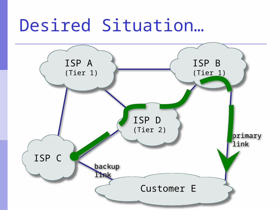
Customer E
ISP A (Tier 1)
ISP C
ISP D (Tier 2)
ISP B (Tier 1)
Desired Situation…
primary link
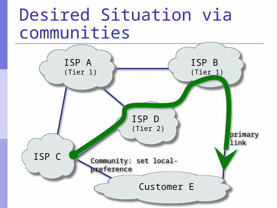
Customer E
ISP A (Tier 1)
ISP C
ISP D (Tier 2)
ISP B (Tier 1)
Desired Situation via communities
Community: set local-preference
Customer E
ISP A (Tier 1)
ISP C
ISP D (Tier 2)
ISP B (Tier 1)
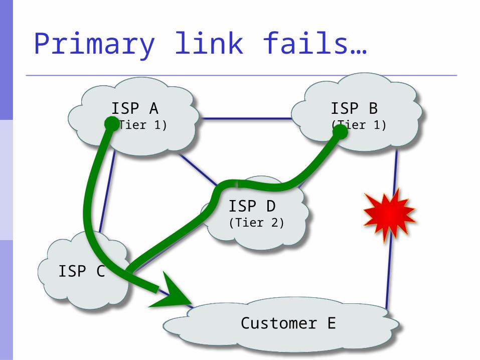
Primary link fails…
Customer E
ISP A (Tier 1)
ISP C
ISP D (Tier 2)
ISP B (Tier 1)
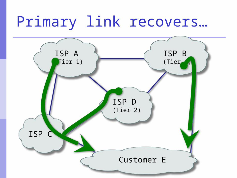
Primary link recovers…
Summary
We have learned: Why we use BGP About the difference between Forwarding
and Routing About Interior and Exterior Routing What the BGP Building Blocks are How to configure BGP Where complexity comes from… Limitations of the “Internet”


