22
Paul Myrda - EPRI & A.P. Meliopoulos and G. J. Cokkinides - Georgia Tech October 21, 2014, Houston, TX Dynamic State Estimation Based Protection: Laboratory Validation
| Date post: | 28-Jul-2018 |
| Category: |
Documents |
| Upload: | truongthuan |
| View: | 214 times |
| Download: | 0 times |
Paul Myrda - EPRI &
A.P. Meliopoulos and G. J. Cokkinides - Georgia Tech
October 21, 2014, Houston, TX
Dynamic State Estimation Based Protection: Laboratory Validation

2 © 2014 Electric Power Research Institute, Inc. All rights reserved.
Contents
• Background and Motivation • Long Term Objectives & Vision • Present Relaying Technology • The Setting-less Protection Approach • Implementation / Examples • Applications • Other Benefits • Substation Based State Estimation • Conclusions

3 © 2014 Electric Power Research Institute, Inc. All rights reserved.
Background and Motivation
• Protective Relay Setting has become Very Complex • New Power Electronic Resource Interfaces Exhibit Fault
Currents Comparable to Load Currents • Detection and Locating of Some Faults is Difficult leading to
Gaps in Protection. • No Substation Level view of Protection • Modeling Errors Play a Major Role in many Control Failures
Wide Area Blackouts • Asset Management is Painful
NERC: #1 Root Cause of System Disturbances
is Protective Relaying
4 © 2014 Electric Power Research Institute, Inc. All rights reserved.
Long Term Objectives / Vision
• Objective • Reduce Complexity • Minimize the “Coordination Role” of the engineer
• Vision • Develop New Dynamic State Estimation Protection Method
• Establish a “GateKeeper” Device – Transmits the Validated Model Upstream (other
substations, control center, enterprise, etc.) • Develop a fully automated protection, control and operation infrastructure
5 © 2014 Electric Power Research Institute, Inc. All rights reserved.
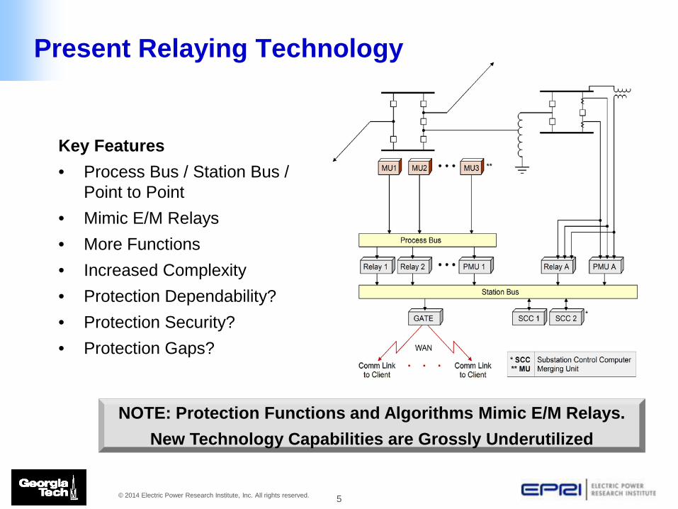
Present Relaying Technology
Key Features • Process Bus / Station Bus /
Point to Point • Mimic E/M Relays • More Functions • Increased Complexity • Protection Dependability? • Protection Security? • Protection Gaps?
NOTE: Protection Functions and Algorithms Mimic E/M Relays. New Technology Capabilities are Grossly Underutilized
6 © 2014 Electric Power Research Institute, Inc. All rights reserved.
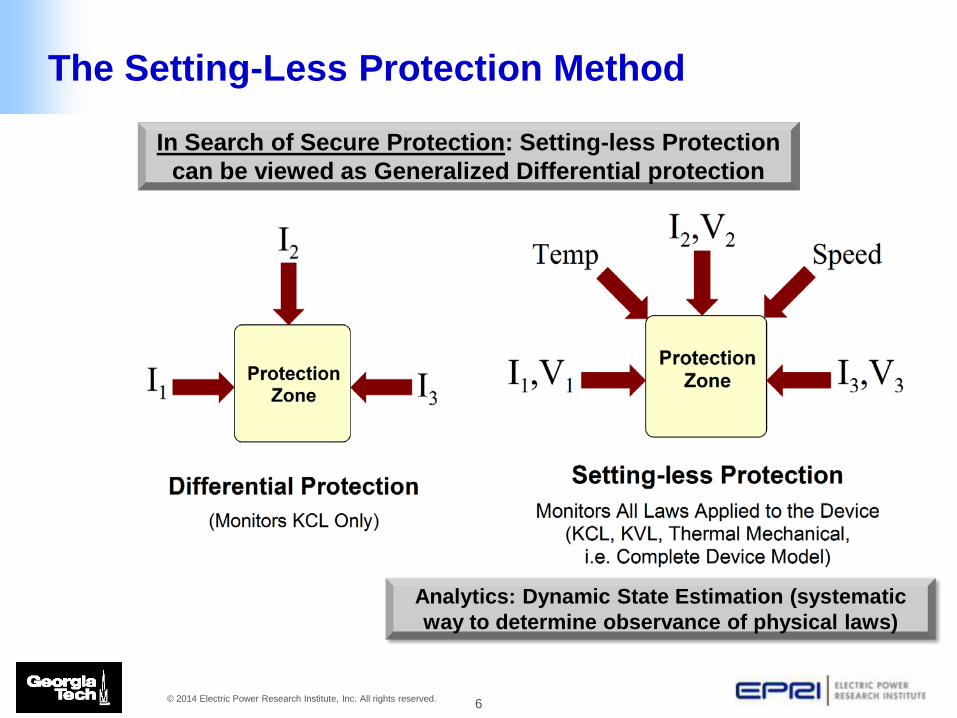
The Setting-Less Protection Method
In Search of Secure Protection: Setting-less Protection can be viewed as Generalized Differential protection
Analytics: Dynamic State Estimation (systematic way to determine observance of physical laws)

7 © 2014 Electric Power Research Institute, Inc. All rights reserved.
Setting-less Protection Approach
1. Measure/Monitor as Many Quantities as Possible and Use Dynamic State Estimation to Continuously Monitor the State (Condition, Health) of the Zone (Component) Under Protection. Identify bad data, model changes, etc.
2. Act on the Basis of the Zone (Component) State (Condition, Component Health).
3. Advantage: No need to know what is happening in the rest of the system – no coordination needed.

8 © 2014 Electric Power Research Institute, Inc. All rights reserved.
Implementation Overview
• The Component is represented with a set of Differential Equations (DE)
• The Dynamic State Estimator fits the Streaming Data to the Dynamic Model (DE) of the Component
• Object Oriented Implementation
9 © 2014 Electric Power Research Institute, Inc. All rights reserved.
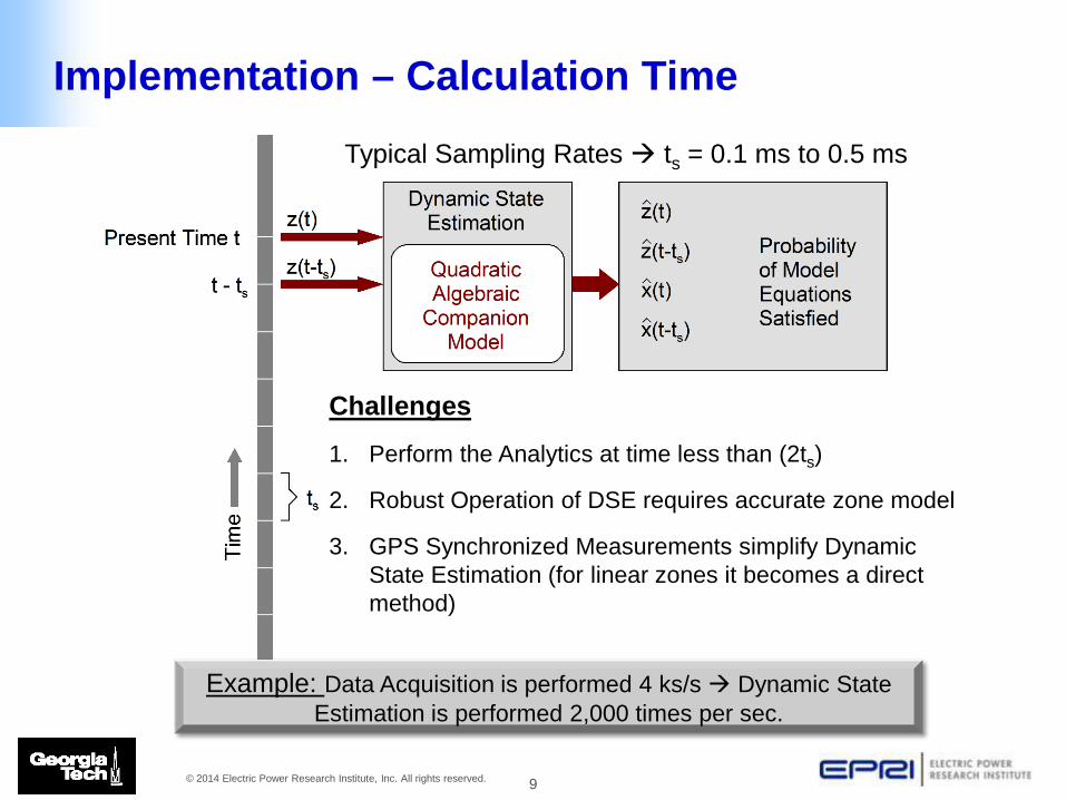
Challenges
1. Perform the Analytics at time less than (2ts)
2. Robust Operation of DSE requires accurate zone model
3. GPS Synchronized Measurements simplify Dynamic State Estimation (for linear zones it becomes a direct method)
Typical Sampling Rates ts = 0.1 ms to 0.5 ms
Example: Data Acquisition is performed 4 ks/s Dynamic State Estimation is performed 2,000 times per sec.
Implementation – Calculation Time

10 © 2014 Electric Power Research Institute, Inc. All rights reserved.
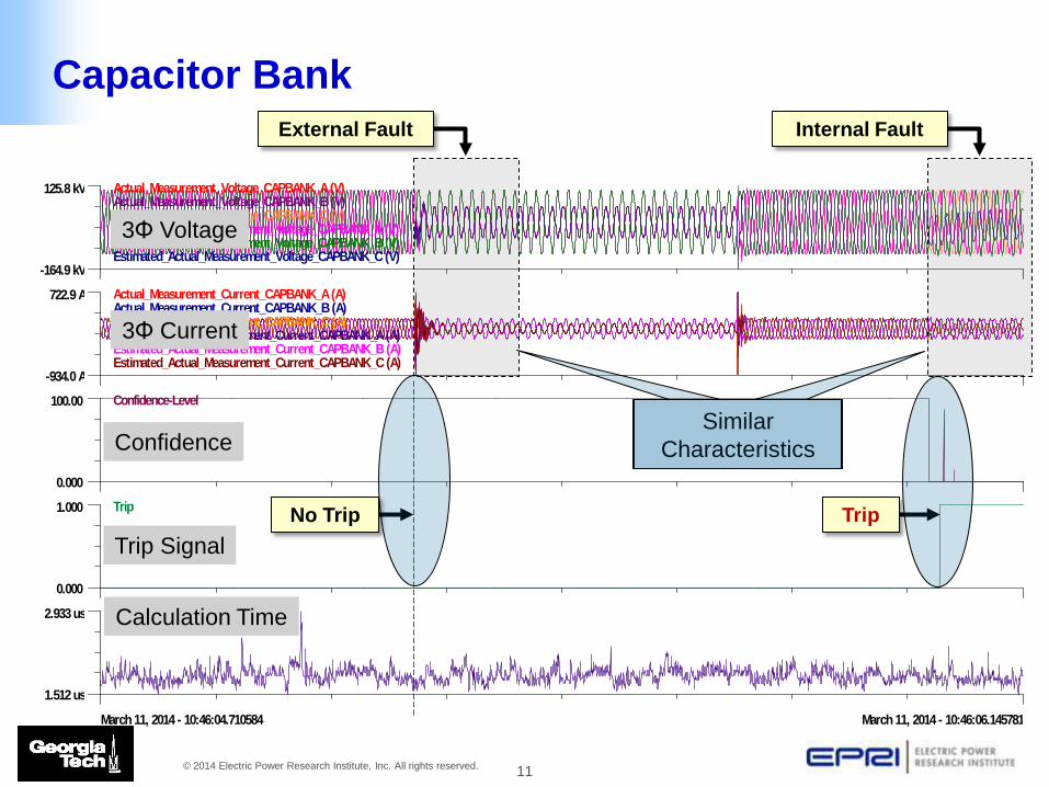
Protection Zone
• 115 kV, 48 MVAr capacitor bank
Event
• A single phase to ground fault at 2.2 seconds and duration 0.5 seconds at the location designated “External Fault”.
• An internal fault in the capacitor bank occurs at 3.0 secs (fault shorted cap cans of phase C, see figure). Fault changes the net capacitance of phase C from 4.8 μF to 2.4 μF.
G
1 2
G
1 2 1 2
GEN CAPBNK
CAP1GUNIT2
JCLIN
E3
LINE
LINETEE
LOAD04
SOURCE1
SOURCE1-T
TXFMRHIGH
TXFMRLO
W
XFMR2H
XFMR2L
YJLINE1
YJLINE2
Relay Inputs (Measurements): • Voltage of phase A-G • Voltage of phase B-G • Voltage of phase C-G • Voltage at neutral point • Current of phase A • Current of phase B • Current of phase C
External Fault Capacitor Bank
Internal Fault
Capacitor Bank
11 © 2014 Electric Power Research Institute, Inc. All rights reserved.
External Fault Internal Fault
Capacitor Bank
125.8 kV
-164.9 kV
Actual_Measurement_Voltage_CAPBANK_A (V)Actual_Measurement_Voltage_CAPBANK_B (V)Actual_Measurement_Voltage_CAPBANK_C (V)Estimated_Actual_Measurement_Voltage_CAPBANK_A (V)Estimated_Actual_Measurement_Voltage_CAPBANK_B (V)Estimated_Actual_Measurement_Voltage_CAPBANK_C (V)
722.9 A
-934.0 A
Actual_Measurement_Current_CAPBANK_A (A)Actual_Measurement_Current_CAPBANK_B (A)Actual_Measurement_Current_CAPBANK_C (A)Estimated_Actual_Measurement_Current_CAPBANK_A (A)Estimated_Actual_Measurement_Current_CAPBANK_B (A)Estimated_Actual_Measurement_Current_CAPBANK_C (A)
100.00
0.000
Confidence-Level
1.000
0.000
Trip
2.933 us
1.512 us
Execution_time_average (s)
March 11, 2014 - 10:46:04.710584 March 11, 2014 - 10:46:06.145781
3Φ Voltage
3Φ Current
Confidence
Trip Signal
Calculation Time
No Trip Trip
Similar Characteristics
12 © 2014 Electric Power Research Institute, Inc. All rights reserved.
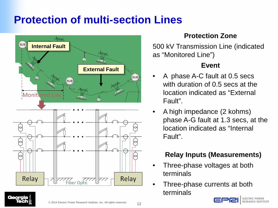
Protection of multi-section Lines Protection Zone
500 kV Transmission Line (indicated as “Monitored Line”)
Event • A phase A-C fault at 0.5 secs
with duration of 0.5 secs at the location indicated as “External Fault”.
• A high impedance (2 kohms) phase A-G fault at 1.3 secs, at the location indicated as “Internal Fault”.
Relay Inputs (Measurements) • Three-phase voltages at both
terminals • Three-phase currents at both
terminals
External Fault
Internal Fault
13 © 2014 Electric Power Research Institute, Inc. All rights reserved.
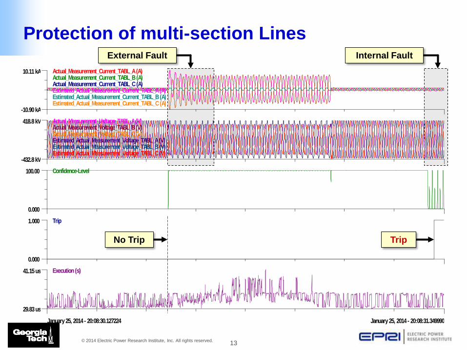
External Fault Internal Fault 10.11 kA
-10.90 kA
Actual_Measurement_Current_TABL_A (A)Actual_Measurement_Current_TABL_B (A)Actual_Measurement_Current_TABL_C (A)Estimated_Actual_Measurement_Current_TABL_A (A)Estimated_Actual_Measurement_Current_TABL_B (A)Estimated_Actual_Measurement_Current_TABL_C (A)
418.8 kV
-432.8 kV
Actual_Measurement_Voltage_TABL_A (V)Actual_Measurement_Voltage_TABL_B (V)Actual_Measurement_Voltage_TABL_C (V)Estimated_Actual_Measurement_Voltage_TABL_A (V)Estimated_Actual_Measurement_Voltage_TABL_B (V)Estimated_Actual_Measurement_Voltage_TABL_C (V)
100.00
0.000
Confidence-Level
1.000
0.000
Trip
41.15 us
29.83 us
Execution (s)
January 25, 2014 - 20:08:30.127224 January 25, 2014 - 20:08:31.349990
No Trip Trip
Protection of multi-section Lines
14 © 2014 Electric Power Research Institute, Inc. All rights reserved.
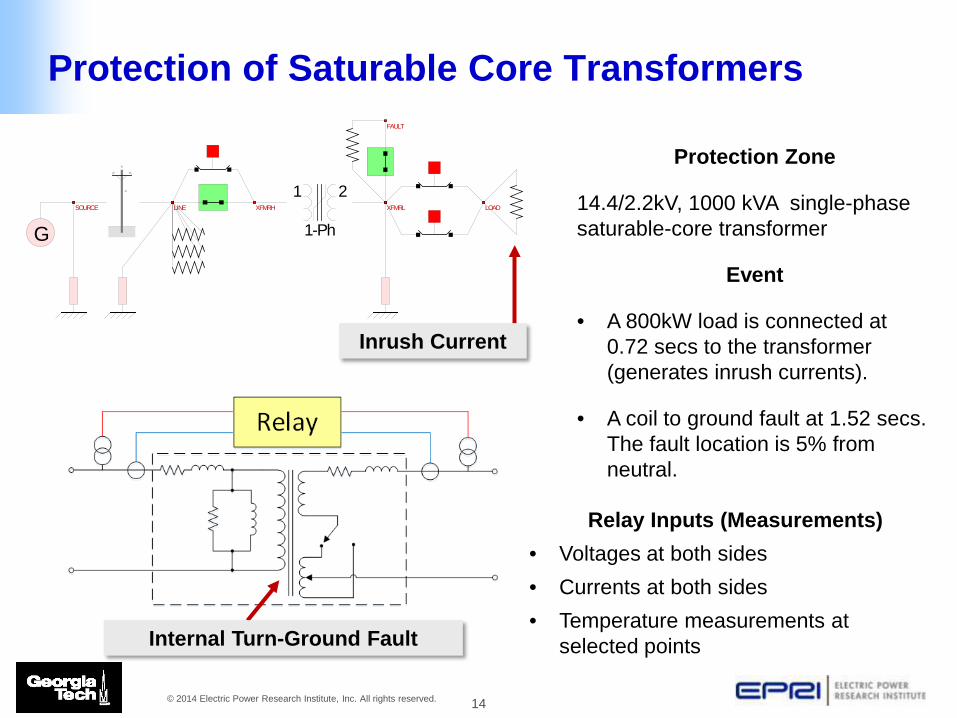
Protection of Saturable Core Transformers
Protection Zone
14.4/2.2kV, 1000 kVA single-phase saturable-core transformer
Event
• A 800kW load is connected at 0.72 secs to the transformer (generates inrush currents).
• A coil to ground fault at 1.52 secs. The fault location is 5% from neutral.
Relay Inputs (Measurements) • Voltages at both sides • Currents at both sides • Temperature measurements at
selected points
1 2
1-PhG
FAULT
LINE LOADSOURCE XFMRH XFMRL
Internal Turn-Ground Fault
Inrush Current
15 © 2014 Electric Power Research Institute, Inc. All rights reserved.
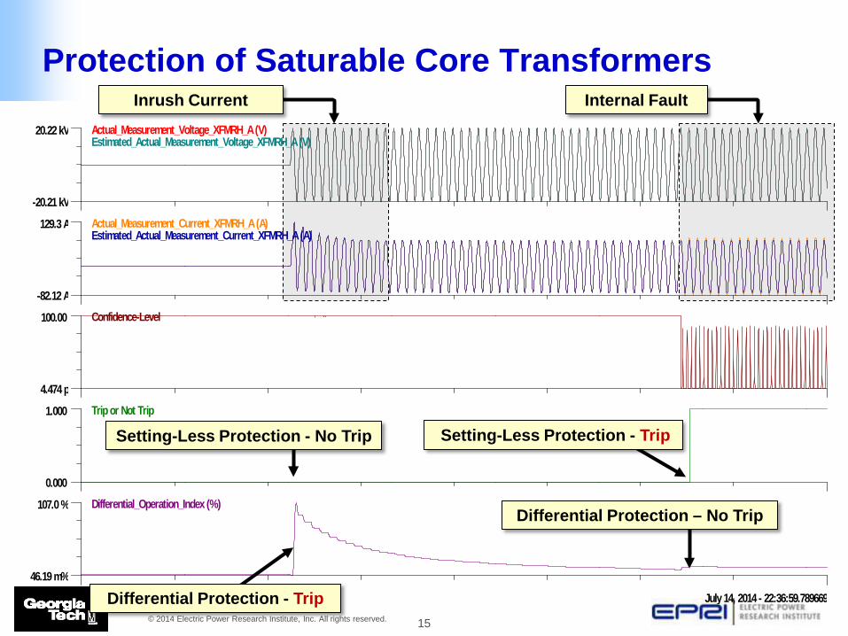
20.22 kV
-20.21 kV
Actual_Measurement_Voltage_XFMRH_A (V)Estimated_Actual_Measurement_Voltage_XFMRH_A (V)
129.3 A
-82.12 A
Actual_Measurement_Current_XFMRH_A (A)Estimated_Actual_Measurement_Current_XFMRH_A (A)
100.00
4.474 p
Confidence-Level
1.000
0.000
Trip or Not Trip
107.0 %
46.19 m%
Differential_Operation_Index (%)
July 14, 2014 - 22:36:58.315318 July 14, 2014 - 22:36:59.789669
Setting-Less Protection - No Trip Setting-Less Protection - Trip
Differential Protection - Trip
Differential Protection – No Trip
Inrush Current Internal Fault
Protection of Saturable Core Transformers
16 © 2014 Electric Power Research Institute, Inc. All rights reserved.
Setting-less Protection Applications
• The following application have been successfully simulated in the lab environment: – Capacitor Bank Protection – Transmission Line Protection – Transformer Protection – Doubly Fed Induction Machine Protection – Saturable Core Reactor Protection – Distribution Line Protection
17 © 2014 Electric Power Research Institute, Inc. All rights reserved.
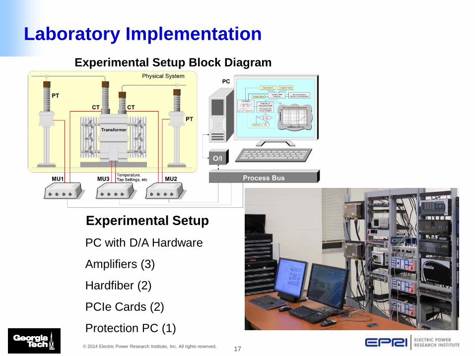
Experimental Setup Block Diagram
Experimental Setup PC with D/A Hardware
Amplifiers (3)
Hardfiber (2)
PCIe Cards (2)
Protection PC (1)
Laboratory Implementation
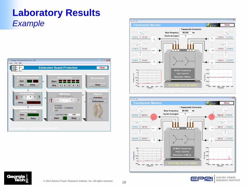
18 © 2014 Electric Power Research Institute, Inc. All rights reserved.
Laboratory Results Example
19 © 2014 Electric Power Research Institute, Inc. All rights reserved.
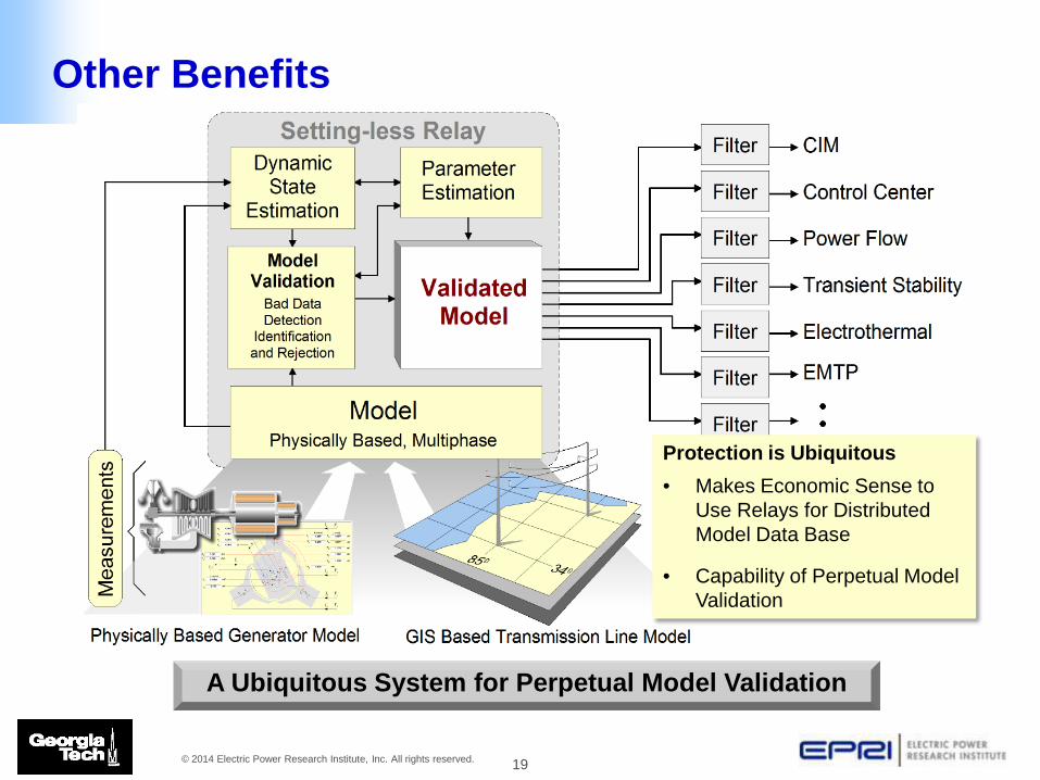
A Ubiquitous System for Perpetual Model Validation
Protection is Ubiquitous • Makes Economic Sense to
Use Relays for Distributed Model Data Base
• Capability of Perpetual Model Validation
Other Benefits
20 © 2014 Electric Power Research Institute, Inc. All rights reserved.
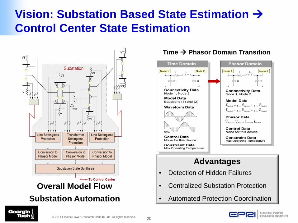
Time Phasor Domain Transition
Overall Model Flow Substation Automation
Vision: Substation Based State Estimation Control Center State Estimation
Advantages • Detection of Hidden Failures
• Centralized Substation Protection
• Automated Protection Coordination

21 © 2014 Electric Power Research Institute, Inc. All rights reserved.
Summary
• Setting-less Protection has been proven in a lab environment in six application areas
• Prototype installation at NYPA under a NYSERDA grant • Multiple secondary benefits
– Model Validation – Detection of Hidden Failures – Distributed State Estimation – Applications

Thank You!
Together . . . Shaping the Future of Electricity


