Dynamic Testing of GE Multilin 869 Motor Protection Relay for Stator Inter-turn Faults by Sallena Choudhury to obtain the degree of Master of Science in Electrical Engineering at the Delft University of Technology, to be defended publicly on Monday August 30, 2021 at 09:00 AM. Student number: 5121833 Project duration: November 20, 2020 – August 30, 2021 Thesis committee: Dr. ing. Marjan Popov, TU Delft, Supervisor Dr. Alex Stefanov, TU Delft Dr. Mohamad Ghaffarian Niasar, TU Delft Ir. Steven de Clippelaar, DOW Benelux Faculty of Electrical Engineering, Mathematics and Computer Science (EEMCS) Delft University of Technology
Transcript
Dynamic Testing of GE Multilin 869 MotorProtection Relay for Stator Inter-turn Faults
by
Sallena Choudhury
to obtain the degree of Master of Science in Electrical Engineeringat the Delft University of Technology,
to be defended publicly on Monday August 30, 2021 at 09:00 AM.
Student number: 5121833Project duration: November 20, 2020 – August 30, 2021Thesis committee: Dr. ing. Marjan Popov, TU Delft, Supervisor
Dr. Alex Stefanov, TU DelftDr. Mohamad Ghaffarian Niasar, TU DelftIr. Steven de Clippelaar, DOW Benelux
Faculty of Electrical Engineering, Mathematics and Computer Science (EEMCS)Delft University of Technology
Science, for me, gives a partial explanation for life.In so far as it goes, it is based on fact,
experience and experiment
Rosalind Franklin
Abstract
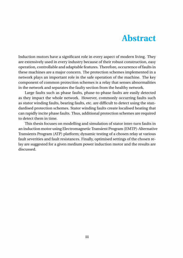
Induction motors have a significant role in every aspect of modern living. Theyare extensively used in every industry because of their robust construction, easyoperation, controllable and adaptable features. Therefore, occurrence of faults inthese machines are a major concern. The protection schemes implemented in anetwork plays an important role in the safe operation of the machine. The keycomponent of common protection schemes is a relay that senses abnormalitiesin the network and separates the faulty section from the healthy network.
Large faults such as phase faults, phase-to-phase faults are easily detectedas they impact the whole network. However, commonly occurring faults suchas stator winding faults, bearing faults, etc. are difficult to detect using the stan-dardised protection schemes. Stator winding faults create localised heating thatcan rapidly incite phase faults. Thus, additional protection schemes are requiredto detect them in time.
This thesis focuses on modelling and simulation of stator inter-turn faults inan induction motor using Electromagnetic Transient Program (EMTP)-AlternativeTransients Program (ATP) platform; dynamic testing of a chosen relay at variousfault severities and fault resistances. Finally, optimised settings of the chosen re-lay are suggested for a given medium power induction motor and the results arediscussed.
iii
Acknowledgements
This thesis was conducted in Intelligent Electric Power Grids (IEPG) group ofElectrical Sustainable Energy department under the Faculty of EEMCS at TU Delft.This was a great opportunity for me to gain some valuable research experienceand this would not have been possible without people who have challenged andmotivated me throughout my time here.
I would first like to thank Dr. ing. Marjan Popov, my supervisor for this thesis.He has been a constant source of motivation and support through my studies,internship as well as my thesis. He has provided valuable guidance, constantencouragement and a platform for me to gain insight in this interesting field.
Secondly, I would also like to thank Ir. Steven De Clippelaar, Power SystemEngineer at DOW Chemical Energy Tech Center for his continuous support inall aspects of the model designing. Thank you for sharing your knowledge andexperience throughout the duration of this thesis.
Thirdly, I would also like to thank Robert Muziol, Application Specialist atGE Grid Automation for his support in relay testing. Thank you for sharing yourexpertise in the field of relay testing.
I would also like to thank the committee members Dr. Alex Stefanov and Dr.Mohamad Ghafarrian Niasar for evaluating my thesis and taking time to be partof the thesis committee.
This experience in TU Delft has been a truly unique one, given that there wasa pandemic amidst the course. I would like to really appreciate all my professors,especially the ones in the Smart AC and DC grids profile, who helped me gaindeep understanding much necessary for conducting this research. All of us wereforced to adapt to new circumstances, but everybody tried their hardest to makethe transition really seamless, and I thank them for that.
Finally, I would like to take this opportunity to thank my parents, sister andfriends. They have always supported and motivated me throughout my stay inthe Netherlands. This has been a journey of fun, frustration and insight whichI’m happy to have experienced with all these people around. Thank you for thememories!
1.1 Percentage chart of faults in an induction motor [1] . . . . . . . . . . 31.2 Flowchart describing the thesis objectives . . . . . . . . . . . . . . . 5
2.1 Equivalent circuit of an induction motor . . . . . . . . . . . . . . . . 82.2 Simulated Induction Motor in ATPDraw. . . . . . . . . . . . . . . . . 142.3 Network of which the induction motor is part of . . . . . . . . . . . . 162.4 Model used to validate the developed model . . . . . . . . . . . . . . 182.5 Comparison of torque plots between the developed and the univer-
sal model . . . . . . . . . . . . . . . . . . . . . . . . . . . . . . . . . . . 192.6 Comparison of speed plots between the developed and the univer-
5.1 Test cases for the testing of relay . . . . . . . . . . . . . . . . . . . . . 445.2 Default Settings for Stator inter-turn fault Detection . . . . . . . . . 455.3 Operating Point and Negative sequence Component for the defined
test cases . . . . . . . . . . . . . . . . . . . . . . . . . . . . . . . . . . . 465.4 Test results of the defined test cases with default settings. . . . . . . 475.5 Modified Settings for Stator inter-turn fault Detection . . . . . . . . 485.6 Test results of the defined test cases with optimised settings. . . . . 495.7 Test cases to determine dead zone . . . . . . . . . . . . . . . . . . . . 51
xi
List of Abbreviations
ATP Alternative Transients Program
COMTRADE Common format for Transient Data Exchange
EMF Electromotive Force
EMTP Electromagnetic Transient Program
EPRI Electric Power Research Institute
MMF Magnetomotive Force
UMIND Universal Induction Machine with Manufacturer’s Data Input
1
1Introduction
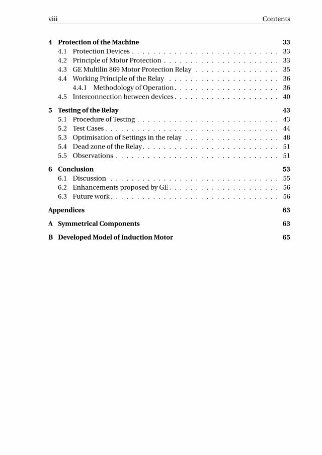
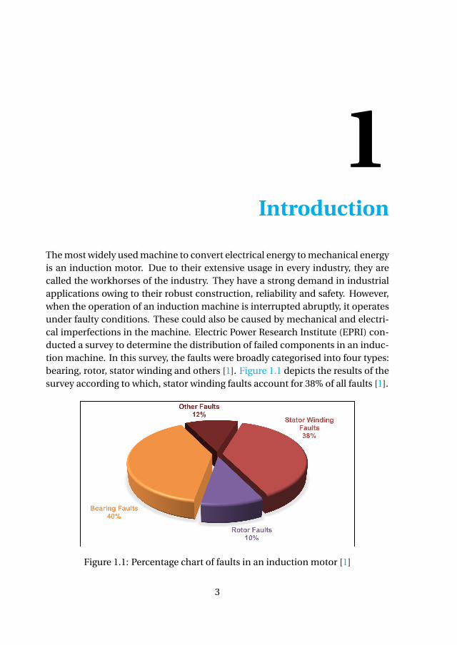
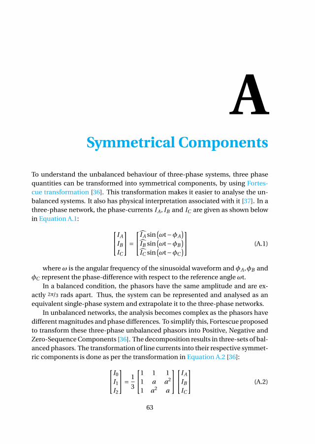
The most widely used machine to convert electrical energy to mechanical energyis an induction motor. Due to their extensive usage in every industry, they arecalled the workhorses of the industry. They have a strong demand in industrialapplications owing to their robust construction, reliability and safety. However,when the operation of an induction machine is interrupted abruptly, it operatesunder faulty conditions. These could also be caused by mechanical and electri-cal imperfections in the machine. Electric Power Research Institute (EPRI) con-ducted a survey to determine the distribution of failed components in an induc-tion machine. In this survey, the faults were broadly categorised into four types:bearing, rotor, stator winding and others [1]. Figure 1.1 depicts the results of thesurvey according to which, stator winding faults account for 38% of all faults [1].
Figure 1.1: Percentage chart of faults in an induction motor [1]
3
1
4 1. Introduction
In most cases, a stator inter-turn fault is caused by thermal stress, vibrationsand ageing process during the operational phase [2]–[4]. These failures affectthe industries due to the increased downtime of the process. Therefore, properprotection is required to avoid these unwanted disturbances in the process. Thisthesis aims at replicating a stator inter-turn fault in a given induction motor, de-tect and optimise the protection relay settings through dynamic testing, even atextremely low fault severity.
1.1. Problem DefinitionInduction machines are expected to have high reliability and long life. This canbe attained by periodic performance checks throughout the life cycle of the ma-chine. However, frequent maintenance checks are expensive and will result inproduction losses. Therefore, accurate online monitoring and diagnosis of fre-quently occurring faults is called for. One of these frequently occurring faults isstator inter-turn fault. This fault can propagate rapidly into a phase-fault andcan cause huge damage. The conventional protection schemes fail to detect thisfault at an early stage. Thus, additional protection schemes are required to iden-tify these faults in time.
1.2. Research QuestionsBased on the presented problem, the following research questions are set to beanswered through this thesis research.
1. How can an induction motor be modelled accurately, to detect stator inter-turn faults?
2. How can the fault current resulting from a stator inter-turn fault be de-tected considering its low magnitude?
3. What is the principle of stator inter-turn fault detection in the chosen pro-tection relay?
4. What are the suitable settings in the chosen protection relay to detect sta-tor inter-turn fault with least severity, without causing any false trips?
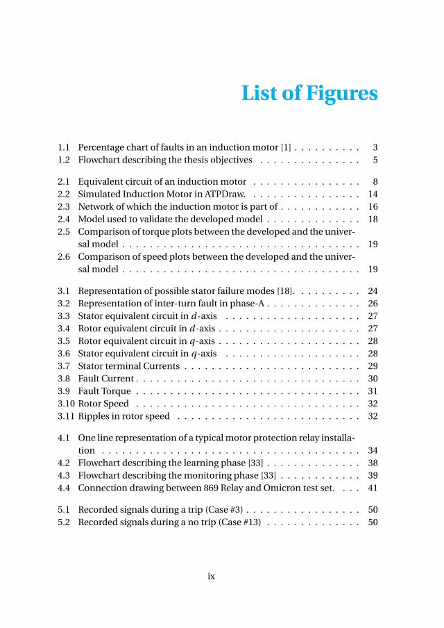
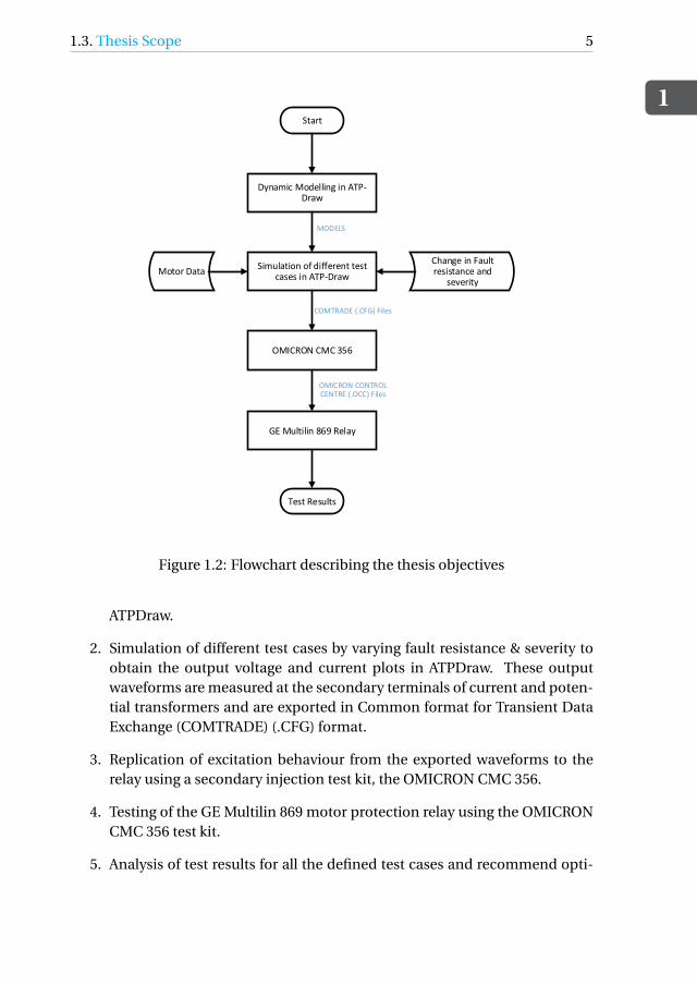
1.3. Thesis ScopeThe flowchart presented in Figure 1.2 describes the procedure followed in thisthesis to find a solution for the above mentioned research questions.
1. Dynamic modelling of the induction motor with stator inter-turn fault us-ing reference frame theory in the MODELS environment of EMTP, version
1.3. Thesis Scope
1
5
Start
Dynamic Modelling in ATP-Draw
Simulation of different test cases in ATP-Draw
OMICRON CMC 356
GE Multilin 869 Relay
Test Results
Motor DataChange in Fault resistance and
severity
MODELS
COMTRADE (.CFG) Files
OMICRON CONTROL CENTRE (.OCC) Files
Figure 1.2: Flowchart describing the thesis objectives
ATPDraw.
2. Simulation of different test cases by varying fault resistance & severity toobtain the output voltage and current plots in ATPDraw. These outputwaveforms are measured at the secondary terminals of current and poten-tial transformers and are exported in Common format for Transient DataExchange (COMTRADE) (.CFG) format.
3. Replication of excitation behaviour from the exported waveforms to therelay using a secondary injection test kit, the OMICRON CMC 356.
4. Testing of the GE Multilin 869 motor protection relay using the OMICRONCMC 356 test kit.
5. Analysis of test results for all the defined test cases and recommend opti-
1
6 1. Introduction
mal settings for the relay.
1.4. Previous WorkPrior to this project, a numerical relay, Siemens Siprotec 7SJ645 motor protec-tion relay was considered for detection of stator inter-turn faults. The principleof protection used in this relay is based on negative sequence overcurrent protec-tion and different characteristics associated with it. This numerical relay imple-ments sequence filter to calculate the symmetrical components from the phasequantities. This relay offered different types of protection settings. For an ac-curate detection, two characteristics of overcurrent protection were considered:definite time and inverse.
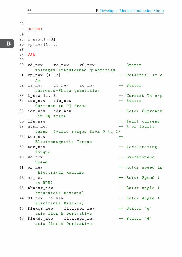
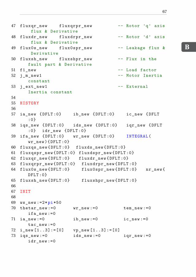
2Modelling of Induction Motor
Induction motors are available in a varied range of voltages and sizes. Small sin-gle phase induction motors majorly find its use in domestic appliances such asblenders, lawn mowers, washing machines etc. Large three phase induction mo-tors are installed in pumps, fans, compressors and similar applications. A linearversion of the induction motor is specifically designed for transportation system.
2.1. Equivalent circuit of an Induction MotorThe working principle of an induction motor is based on the Faraday’s law ofelectromagnetic induction in which Electromotive Force (EMF) are induced acrosselectrical conductors when they are placed in a rotating magnetic field. The twoessential components of the induction motor are stator and rotor. The stator is astationary part and is composed of high grade steel laminations. The inner frameof the stator consists of slots that carries the overlapping windings. In a threephase motor, these windings are physically placed 120°apart to maintain a sinu-soidal nature. The rotor is the rotating part and is composed of ferro-magneticmaterial, with slots on it’s outer surface that carries the field windings. Based onthe type of windings in the rotor, induction motors can be of two types, squirrel-cage or wound-rotor type. In a squirrel-cage type rotor, the windings at the endsare shorted using end rings, whereas in a wound-rotor type, the terminals of thewindings are closed through an external resistance. Since, a squirrel-cage typemotor requires less maintenance, is simple and economical, it is a preferred op-tion in the industry
Based on the Lenz’s law, the direction of rotation of the rotor is along therotating field such that the relative speed between the field and the winding de-creases. The rotor will eventually reach a steady-state speed n which is less than
7
2
8 2. Modelling of Induction Motor
the synchronous speed ns which is the speed of the rotating field. The rotor neverreaches the ns as it has to maintain a relative motion between the rotating mag-netic field and the stationary conductors. The relative motion induces an EMFin the rotor. If this relativity is not achieved, no emf is induced and hence no in-duced current in the rotor to produce torque. The difference between the rotorspeed n and the synchronous speed ns is known as slip (s) and is defined as :
s = ns −n
ns
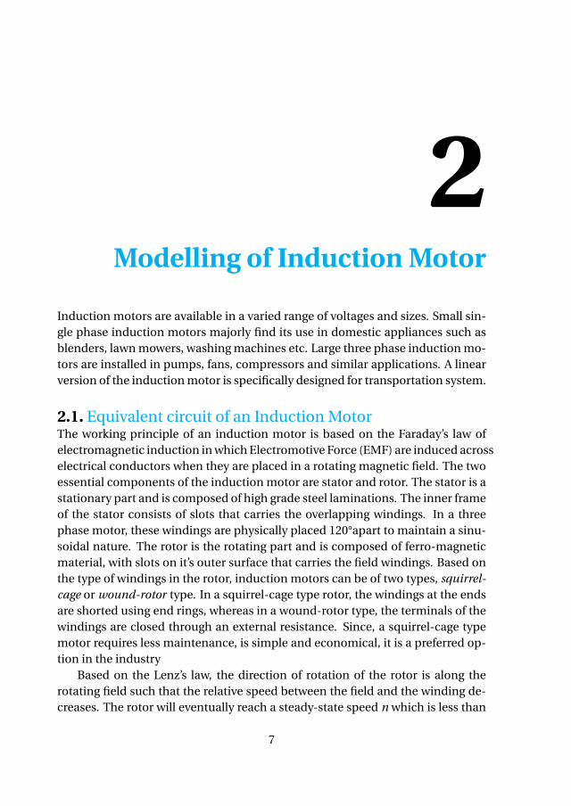
Generally, the value of slip at full load varies from less than 1% in high powermotors to less than 2% in small motors. An induction motor can be representedas a circuit model which includes elements like stator and rotor impedance, andmutual reactance. The linking of the stator and rotor circuits can be consideredas an ideal generalised transformer in which the standstill rotor voltage and ro-tor current are linked to the stator via a transformation ratio a. In the equivalentcircuit, the rotor impedances are referred to the stator side using this transfor-mation ratio. The frequency of the motor appears in the rotor through slip s.Therefore, in the equivalent circuit, the rotor impedance is referred to the sta-tor side in two-step method: transformation using turn ratio and then frequencytransformation to the stator frequency. The per-phase equivalent circuit of thetransformed induction motor is as depicted in the Figure 2.1.
IsRs Ll s
Iφ
Ic
Rc
Im
Lm
IrLl r
Rrs
+
−
Vs
Figure 2.1: Equivalent circuit of an induction motor
where,
2.2. Dynamic Modelling of Induction motor
2
9
Vs : Stator Voltage
Is : Stator Current
Ir : Rotor Current
Rs : Stator Resistance
Ll s : Stator Leakage Inductance
Rc : Core loss Resistance
Lm : Magnetising Inductance
Rr : Referred Rotor Resistance
Ll r : Referred Rotor Leakage Inductance
The equivalent circuit model can assume a form similar to that of an trans-former. The stator circuit is similar to that of the primary side of a transformerand the rotor circuit, when represented from the point of view of stator side, rep-resent the secondary side when referred to the primary side. The difference liesin the magnitude of some parameters. For example, the excitation current, Iφ, isas high as 30% to 50% of the rated current, whereas it lies between 1% to 5% intransformers. Similarly, the leakage reactance of an induction motor is substan-tially higher than that of a transformer due to the air gap and because the statorand rotor windings are distributed along the periphery of the air gap whereas ina transformer, it is concentrated on it’s core.
Induction motors have nearly constant-speed characteristics with variationin loads. The air-gap flux in the induction motor is solely generated based on thestator excitation. The torque developed in an induction motor is dependent onthe induced current in the rotor which runs at a non-synchronous speed; hence,the name asynchronous. Unlike induction motors, the synchronous machinerequires an additional field excitation in the rotor. The torque developed in syn-chronous machine is dependent on the locking of fields of stator and rotor whichoccurs at synchronous speed. Therefore, induction motors remain unperturbedby the stability issue which is inherent to the synchronous machines that operateonly at a single speed.
2.2. Dynamic Modelling of Induction motorAn accurate modelling of an induction motor is important to aid in fault predic-tion and detection. There are multiple ways to develop an induction motor withfault. The most commonly used methods are:
• Modelling based on dynamic equations of the motor with additional cur-rent loops representing the fault.
• Finite element modelling of the motor with modifications in the geometryto accommodate the fault.
2
10 2. Modelling of Induction Motor
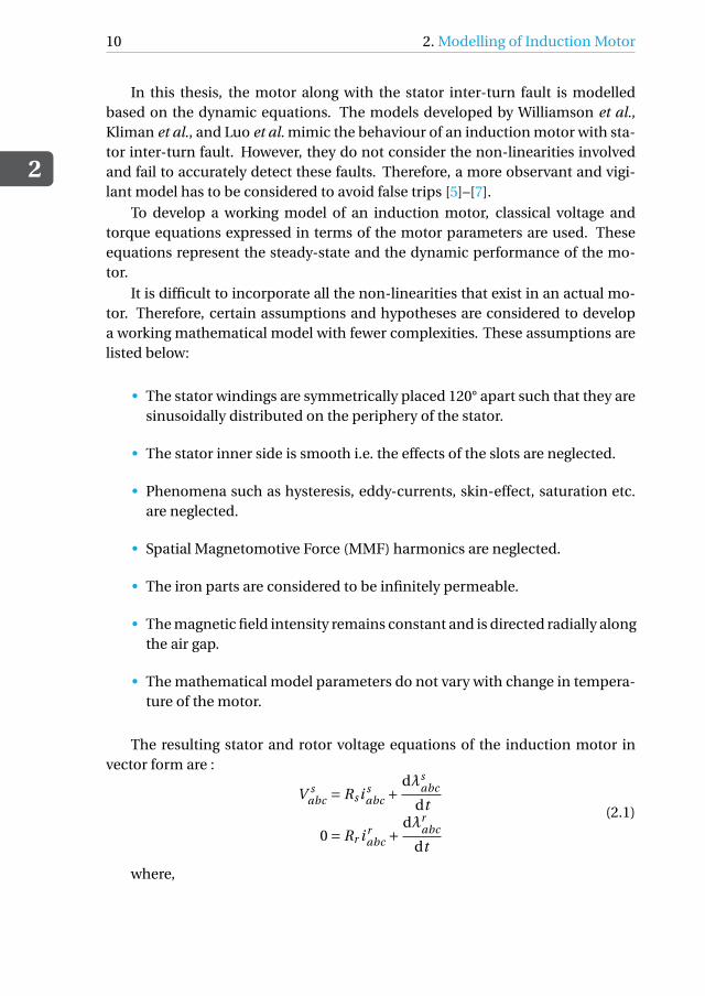
In this thesis, the motor along with the stator inter-turn fault is modelledbased on the dynamic equations. The models developed by Williamson et al.,Kliman et al., and Luo et al. mimic the behaviour of an induction motor with sta-tor inter-turn fault. However, they do not consider the non-linearities involvedand fail to accurately detect these faults. Therefore, a more observant and vigi-lant model has to be considered to avoid false trips [5]–[7].
To develop a working model of an induction motor, classical voltage andtorque equations expressed in terms of the motor parameters are used. Theseequations represent the steady-state and the dynamic performance of the mo-tor.
It is difficult to incorporate all the non-linearities that exist in an actual mo-tor. Therefore, certain assumptions and hypotheses are considered to developa working mathematical model with fewer complexities. These assumptions arelisted below:
• The stator windings are symmetrically placed 120° apart such that they aresinusoidally distributed on the periphery of the stator.
• The stator inner side is smooth i.e. the effects of the slots are neglected.
• Phenomena such as hysteresis, eddy-currents, skin-effect, saturation etc.are neglected.
• Spatial Magnetomotive Force (MMF) harmonics are neglected.
• The iron parts are considered to be infinitely permeable.
• The magnetic field intensity remains constant and is directed radially alongthe air gap.
• The mathematical model parameters do not vary with change in tempera-ture of the motor.
The resulting stator and rotor voltage equations of the induction motor invector form are :
V sabc = Rs i s
abc +dλs
abc
dt
0 = Rr i rabc +
dλrabc
dt
(2.1)
where,
2.2. Dynamic Modelling of Induction motor
2
11
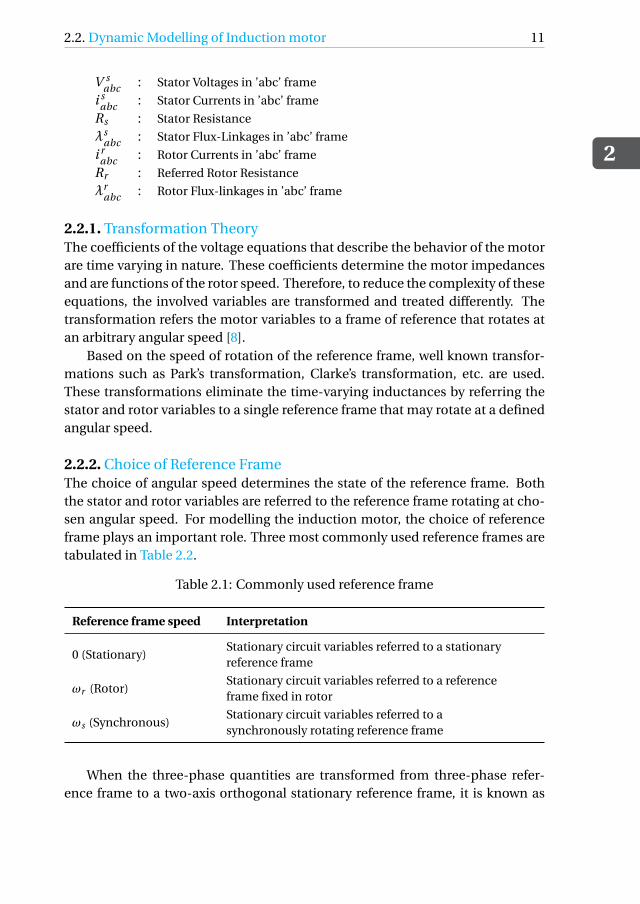
V sabc : Stator Voltages in ’abc’ frame
i sabc : Stator Currents in ’abc’ frame
Rs : Stator Resistance
λsabc : Stator Flux-Linkages in ’abc’ frame
i rabc : Rotor Currents in ’abc’ frame
Rr : Referred Rotor Resistance
λrabc : Rotor Flux-linkages in ’abc’ frame
2.2.1. Transformation TheoryThe coefficients of the voltage equations that describe the behavior of the motorare time varying in nature. These coefficients determine the motor impedancesand are functions of the rotor speed. Therefore, to reduce the complexity of theseequations, the involved variables are transformed and treated differently. Thetransformation refers the motor variables to a frame of reference that rotates atan arbitrary angular speed [8].
Based on the speed of rotation of the reference frame, well known transfor-mations such as Park’s transformation, Clarke’s transformation, etc. are used.These transformations eliminate the time-varying inductances by referring thestator and rotor variables to a single reference frame that may rotate at a definedangular speed.
2.2.2. Choice of Reference FrameThe choice of angular speed determines the state of the reference frame. Boththe stator and rotor variables are referred to the reference frame rotating at cho-sen angular speed. For modelling the induction motor, the choice of referenceframe plays an important role. Three most commonly used reference frames aretabulated in Table 2.2.
Table 2.1: Commonly used reference frame
Reference frame speed Interpretation
0 (Stationary)Stationary circuit variables referred to a stationaryreference frame
ωr (Rotor)Stationary circuit variables referred to a referenceframe fixed in rotor
ωs (Synchronous)Stationary circuit variables referred to asynchronously rotating reference frame
When the three-phase quantities are transformed from three-phase refer-ence frame to a two-axis orthogonal stationary reference frame, it is known as
2
12 2. Modelling of Induction Motor
Clarke’s transformation. In this transformation, the two stationary two-phasevariables are denoted as α and β which are orthogonal to each other. Further-more, the resulting two-phase orthogonal quantities can be transformed to arotary reference frame with arbitrary angular speed, which is known as Park’stransformation.
For convenient modelling of the induction motor in this thesis, the stationaryreference frame is chosen i.e. Clarke’s transformation. A power invariant form ofthis transformation is used to transform all the stator and rotor variables into itsrespective α and β components using the transformation matrix Xd q0.
The transformed variables can be restored to their original form by using theinverse transformation matrix Xabc .
Xabc =√
2
3
cos(ωt ) −sin(ωt ) 1/p
2
cos(ωt − 2π/3) −sin(ωt − 2π/3) 1/p
2
cos(ωt + 2π/3) −sin(ωt + 2π/3) 1/p
2
Xd
Xq
X0
(2.3)
Based on the transformation presented in (2.2), the voltage equations in (2.1)are transformed as follows:
Vd s = Rs id s −ωλqs + dλd s
dt
Vqs = Rs iqs +ωλd s +dλqs
dt
Vqr = Rr iqr + (ω−ωr )λdr +dλqr
dt
Vdr = Rr idr − (ω−ωr )λqr + dλdr
dt
(2.4)
From the above-mentioned equations, the flux-linkages are defined as fol-lows:
λd s = Ls id s +Lmidr
λqs = Ls iqs +Lmiqr
λdr = Lr idr +Lmid s
λqr = Lr iqr +Lmiqs
(2.5)
where Ls and Lr are the stator and rotor inductance respectively, and are de-fined as follows:
2.3. Simulation in ATP-Draw
2
13
Ls = Ll s +Lm
Lr = Ll r +Lm(2.6)
where,V s
d q : Transformed Stator Voltages
i sd q : Transformed Stator Currents
Rs : Stator Resistance
Ls : Stator Inductance
λsd q : Transformed Stator Flux
i rd q : Transformed Rotor Currents
Rr : Referred Rotor Resistance
Lr : Referred Rotor Inductance
λrd q : Transformed Rotor Flux-linkages
ω : Rotational Frame Speed
ωr : Rotor Speed
2.3. Simulation in ATP-DrawTo predict the dynamic performance of an induction motor, it is simulated dig-itally. The primordial models used the exact equivalent circuit to represent aninduction motor. These models used lumped circuit model parameters as theywere based on the concept of magnetically coupled circuits. But these modelsdid not include certain phenomena such as motor start up. Therefore, with rel-evant research in the digital computing, changes were made to the modellingtechnique and circuit models are generated with more accuracy.
Various digital computer programs are used to simulate ac motors and de-termine their dynamic performance and transient phenomena. In this thesis,EMTP-ATP is used. It is a program developed dedicated to study the potentialproblems in an electrical power system. This program helps characterise tran-sient events as they have a wide range of modelling capabilities and simulatethem within few microseconds.
EMTP-ATP has a default component known as "universal machine" that con-tains majority of the functions of an induction motor. This component requiresvery little information about the motor for its operation as an induction motor.This model is designed based on "direct-quadrature axes" theory. The internalmodelling requires the following information about the motor:
• Stator Resistance (Rs)
• Referred Rotor Resistance (Rr )
• Magnetising Inductance (Lm)
2
14 2. Modelling of Induction Motor
• Stator Leakage Inductance (Ls)
• Referred Rotor Leakage Inductance (Lr 1)
• Moment of Inertia (J )
• External Load torque (TL)
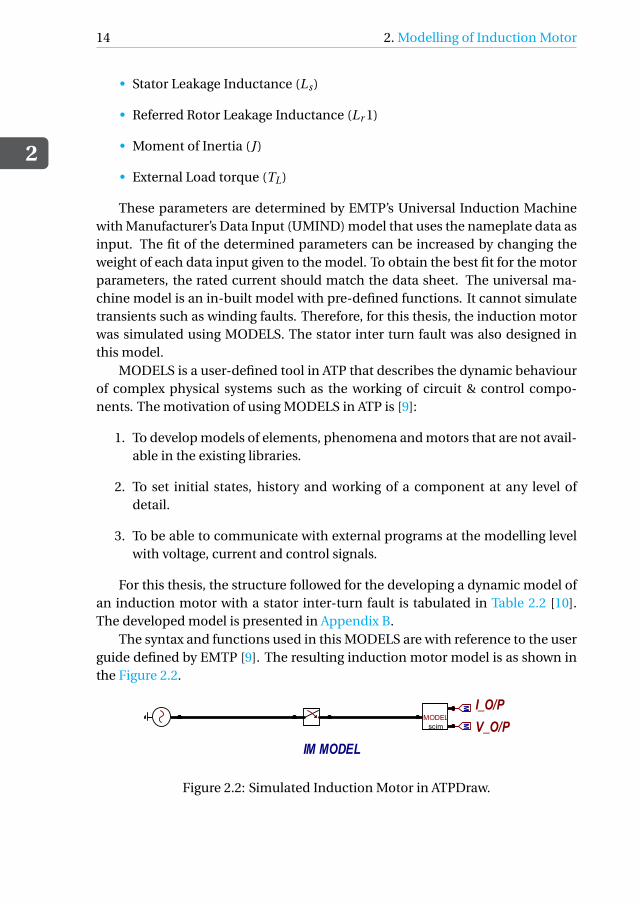
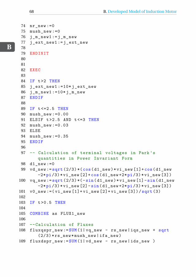
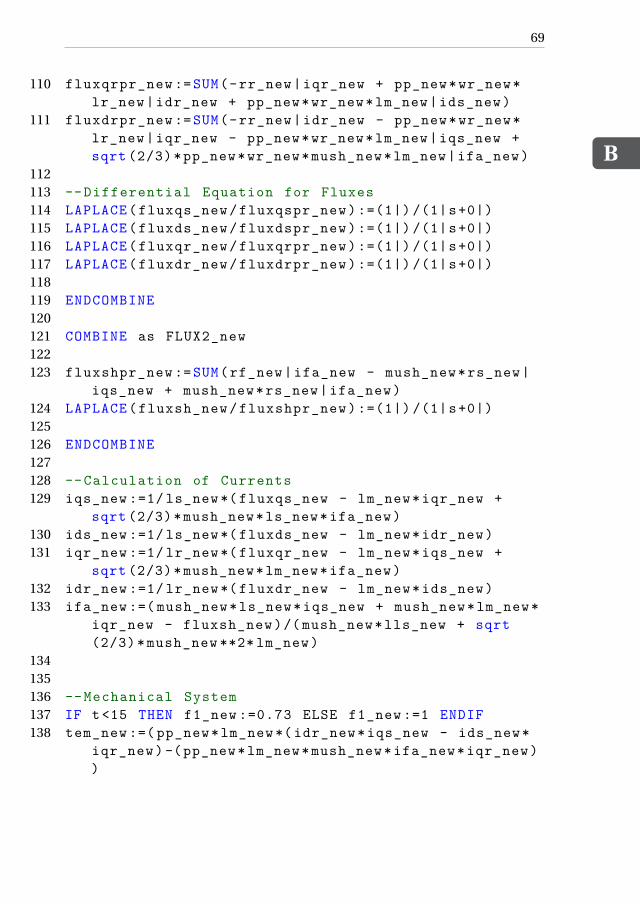
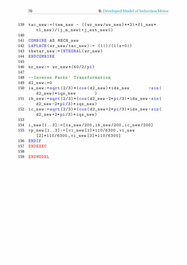
These parameters are determined by EMTP’s Universal Induction Machinewith Manufacturer’s Data Input (UMIND) model that uses the nameplate data asinput. The fit of the determined parameters can be increased by changing theweight of each data input given to the model. To obtain the best fit for the motorparameters, the rated current should match the data sheet. The universal ma-chine model is an in-built model with pre-defined functions. It cannot simulatetransients such as winding faults. Therefore, for this thesis, the induction motorwas simulated using MODELS. The stator inter turn fault was also designed inthis model.
MODELS is a user-defined tool in ATP that describes the dynamic behaviourof complex physical systems such as the working of circuit & control compo-nents. The motivation of using MODELS in ATP is [9]:
1. To develop models of elements, phenomena and motors that are not avail-able in the existing libraries.
2. To set initial states, history and working of a component at any level ofdetail.
3. To be able to communicate with external programs at the modelling levelwith voltage, current and control signals.
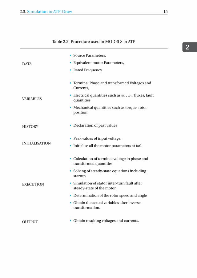
For this thesis, the structure followed for the developing a dynamic model ofan induction motor with a stator inter-turn fault is tabulated in Table 2.2 [10].The developed model is presented in Appendix B.
The syntax and functions used in this MODELS are with reference to the userguide defined by EMTP [9]. The resulting induction motor model is as shown inthe Figure 2.2.
MODELscim
IM MODEL
I_O/P
V_O/P
MM
Torque(init)
IM
w
M
U(0)
+
Iner
tia M
Torq. source
D_M
otor
MT [Nm]
Torq. model
SourceI
ui
PQ
Figure 2.2: Simulated Induction Motor in ATPDraw.
2.3. Simulation in ATP-Draw
2
15
Table 2.2: Procedure used in MODELS in ATP
DATA
• Source Parameters,
• Equivalent motor Parameters,
• Rated Frequency.
VARIABLES
• Terminal Phase and transformed Voltages andCurrents,
• Electrical quantities such as ωr , ωr , fluxes, faultquantities
• Mechanical quantities such as torque, rotorposition.
HISTORY • Declaration of past values
INITIALISATION• Peak values of input voltage,
• Initialise all the motor parameters at t=0.
EXECUTION
• Calculation of terminal voltage in phase andtransformed quantities,
• Solving of steady-state equations includingstartup
• Simulation of stator inter-turn fault aftersteady-state of the motor,
• Determination of the rotor speed and angle
• Obtain the actual variables after inversetransformation.
OUTPUT • Obtain resulting voltages and currents.
2
16 2. Modelling of Induction Motor
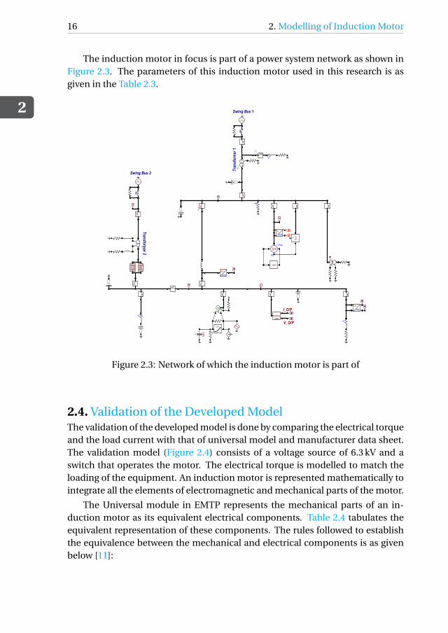
The induction motor in focus is part of a power system network as shown inFigure 2.3. The parameters of this induction motor used in this research is asgiven in the Table 2.3.
Swing Bus 1
V
SAT
YZ
I
BC
T
Y
Tran
sfor
mer
1
BC
T
YY
Transformer 2
Swing Bus 2
T [Nm]
V
V
D
M
M
V
ui
PQ
abc
rms
M
TEx
TPow
58
SM
V
ST61
GOV
ui
PQ
MM
IU(0)
+
IM
w
MODELscim
I_O/P
V_O/P
MM
Figure 2.3: Network of which the induction motor is part of
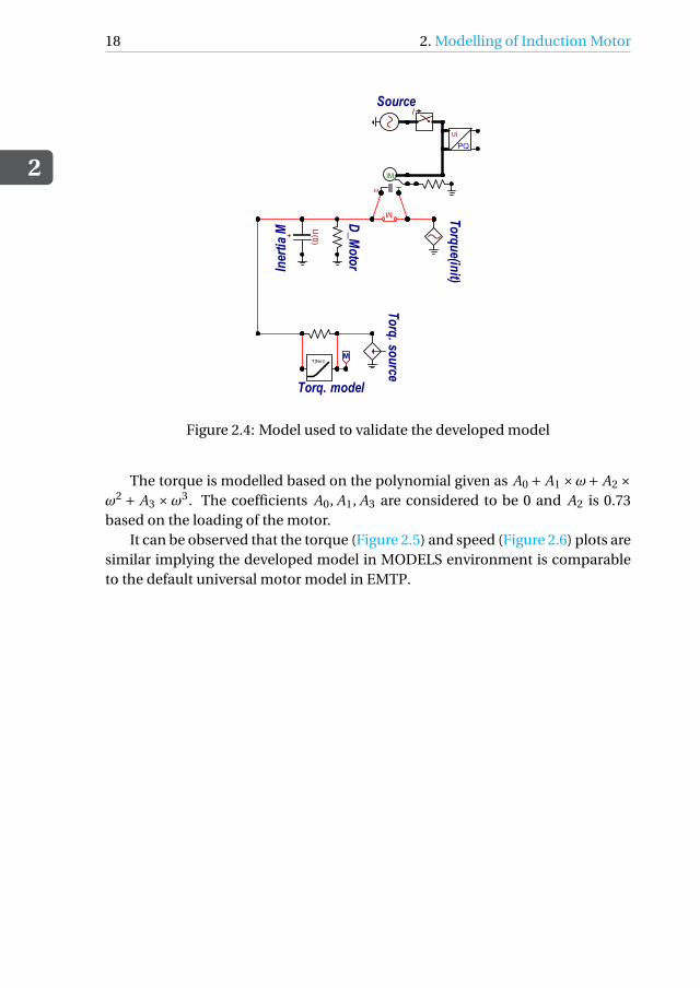
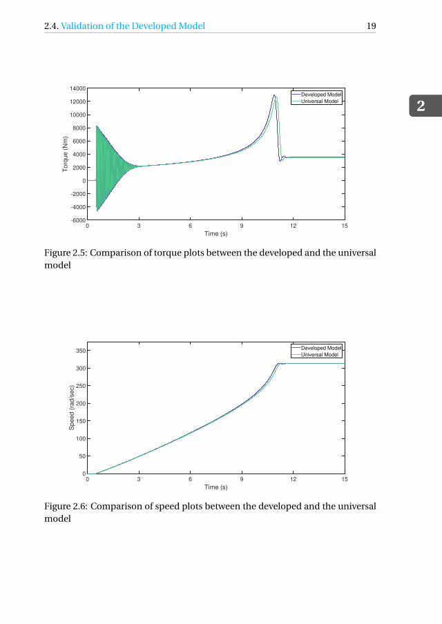
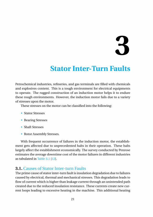
2.4. Validation of the Developed ModelThe validation of the developed model is done by comparing the electrical torqueand the load current with that of universal model and manufacturer data sheet.The validation model (Figure 2.4) consists of a voltage source of 6.3 kV and aswitch that operates the motor. The electrical torque is modelled to match theloading of the equipment. An induction motor is represented mathematically tointegrate all the elements of electromagnetic and mechanical parts of the motor.
The Universal module in EMTP represents the mechanical parts of an in-duction motor as its equivalent electrical components. Table 2.4 tabulates theequivalent representation of these components. The rules followed to establishthe equivalence between the mechanical and electrical components is as givenbelow [11]:
2.4. Validation of the Developed Model
2
17
Table 2.3: Machine Parameters of the modelled induction motor
• In the equivalent network, the moment of inertia is represented as a nodewith a capacitor to ground for the mass of the shaft.
• In the equivalent network, a current source is connected to the mass nodeupon which mechanical torque is acting.
• The damping proportional to the speed is represented as a resistor in par-allel to a capacitor.
• Two or more masses are represented as inductors.
• Damping associated to coupling is represented as inductor in parallel to aresistor.
Table 2.4: Equivalent representation between mechanical and electrical compo-nents [11]
Mechanical Parameter Electrical Representation
Torque acting on mass (T ) Current into a node (i )Angular Speed (ω) Node Voltage (v)
Angular position (θ) Capacitor Charge(q)
Moment of inertia (J ) Capacitance to ground (C )Spring Constant (K ) Reciprocal of Inductance (1/L)
Damping Coefficient (D) Conductance (G)
2
18 2. Modelling of Induction Motor
MODELscim
IM MODEL
I_O/P
V_O/P
MM
Torque(init)
IM
w
M
U(0)
+
Iner
tia M
Torq. source
D_M
otorM
T [Nm]
Torq. model
SourceI
ui
PQ
Figure 2.4: Model used to validate the developed model
The torque is modelled based on the polynomial given as A0 + A1 ×ω+ A2 ×ω2 + A3 ×ω3. The coefficients A0, A1, A3 are considered to be 0 and A2 is 0.73based on the loading of the motor.
It can be observed that the torque (Figure 2.5) and speed (Figure 2.6) plots aresimilar implying the developed model in MODELS environment is comparableto the default universal motor model in EMTP.
2.4. Validation of the Developed Model
2
19
0 3 6 9 12 15
Time (s)
-6000
-4000
-2000
0
2000
4000
6000
8000
10000
12000
14000
To
rqu
e (
Nm
)
Developed Model
Universal Model
Figure 2.5: Comparison of torque plots between the developed and the universalmodel
0 3 6 9 12 15
Time (s)
0
50
100
150
200
250
300
350
Sp
ee
d (
rad
/se
c)
Developed Model
Universal Model
Figure 2.6: Comparison of speed plots between the developed and the universalmodel
3Stator Inter-Turn Faults
Petrochemical industries, refineries, and gas terminals are filled with chemicalsand explosives content. This is a tough environment for electrical equipmentsto operate. The rugged construction of an induction motor helps it to endurethese rough environments. However, the induction motor fails due to a varietyof stresses upon the motor.
These stresses on the motor can be classified into the following:
• Stator Stresses
• Bearing Stresses
• Shaft Stresses
• Rotor Assembly Stresses.
With frequent occurrence of failures in the induction motor, the establish-ment gets affected due to unprecedented halts in their operation. These haltslargely affect the establishment economically. The survey conducted by Penroseestimates the average downtime cost of the motor failures in different industriesas tabulated in Table 3.1 [12].
3.1. Causes of Stator Inter-turn FaultsThe prime cause of stator inter-turn fault is insulation degradation due to failurescaused by electrical, thermal and mechanical stresses. This degradation leads toflow of current which is higher than leakage current through an unintended pathcreated due to the reduced insulation resistance. These currents create new cur-rent loops leading to excessive heating in the machine. This additional heating
expedites the process of insulation degradation [13]. Overvoltage stresses is themost probable cause of electrical and thermal stresses on the machine. The volt-age gradient across a winding is highest at the first few turns. Therefore, the oc-currence of stator inter-turn fault at these locations is highly probable. Mechan-ical and chemical stresses can also be responsible for insulation degradation. Aninduction machine in a contaminated environment is susceptible to pollutantsthat may affect the insulation between turns by creating a path for small currentsto flow [14].
3.2. Consequences of Stator inter-turn faultsA stator inter-turn fault is generally a consequence of combination of stresses:ageing, contamination, exposure to chemical substances, moisture, heat, largetransients in the motor. The fault starts with a degradation of the insulation ma-terial leading to breakdown of adjacent turns’ insulation and thus leading to in-cipient stator inter-turn short circuit fault [15].
The effect of an inter-turn fault on an induction motor is as follows [16]:
1. The fault creates asymmetries in the balanced three phase circuit whichresults in varying amplitudes of stator current.
2. The fault increases the harmonics in the air gap flux, breaks the symmet-ric magnetic line of force and increases the saturation degree of magneticdensity with deepening of fault severity.
3. The fault introduces ripples in the electromagnetic torque. These ripplesincrease with growing fault severity which affects the operational stabilityof the system.
4. The fault creates localised heating which can be proved dangerous in in-dustries with volatile work environment.
3.3. Stator Inter-turn Fault Detection Techniques
3
23
Ideally the insulation resistance is infinite and the fault current is zero beforethe fault is incepted. However, with the degradation of the insulation material,the insulation resistance tends to zero and value of fault current increases. Theeffective turns on the faulty phase are reduced during the fault. This reductionaffects the MMF induced in the healthy section. Along with the reduced MMF,the fault current produces MMF in the opposite direction that weakens the exist-ing one in the faulty phase.
The faulty phase can be considered as an auto transformer where the entirephase is the primary side while the faulty part is the secondary. Subsequently,high currents are induced in the secondary side based on the transformation ra-tio:
N1
N2= I2
I1
The fault current causes abnormal heating and spreads to the surroundingwindings resulting in a sequential phase to ground or phase to phase fault. Hence,timely detection of the stator inter-turn fault can prevent severe damages andhuge downtime of the motor. But, the fault current is not reflected at the statorterminals which becomes a challenge in the detection of the fault.
3.3. Stator Inter-turn Fault Detection TechniquesA stator winding fault starts with failure of insulation between two turns in aphase of the stator. The shorted turn affects the surrounding turns leading toa insulation failure in the stator. The faulty turns generate circulating currentwhich increases the temperature in the affected area as the machine continuesto operate. The increased temperature may further damage the insulation of theneighbouring areas.
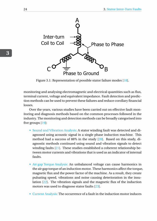
The occurrence of inter-turn fault can propagate to larger sections of thewinding resulting into a coil-to-coil short circuit or phase-to-phase short cir-cuit [17]. Figure 3.1 represents different types of possible stator failure modes.These faults can further develop into phase-to-ground faults causing significantdamage to the machine. Such failures can cause large fault current, resulting inirreversible damage to the machine [13].
The main cause of such failures can be accounted for the different types ofstress i.e. mechanical, thermal, electrical, and environmental the machine un-dergoes during its operating life. The increased prevalence of the fault makes ita pressing matter to identify and adopt diagnostic techniques to avoid furtherfailures. If they go undiagnosed, reduced efficiency, increased costs and reducedoperating life can be expected. Continuous development in the sector of the dig-ital signal processing and sensing helps researchers to develop monitoring andtesting techniques for inter-turn faults. These techniques rely on non-invasive
3
24 3. Stator Inter-Turn Faults
A
C B
Inter-turn
Phase to Phase
Phase to Ground
Coil to Coil
Figure 3.1: Representation of possible stator failure modes [18].
monitoring and analysing electromagnetic and electrical quantities such as flux,terminal current, voltage and equivalent impedance. Fault detection and predic-tion methods can be used to prevent these failures and reduce corollary financiallosses.
Over the years, various studies have been carried out on effective fault mon-itoring and diagnosis methods based on the common processes followed in theindustry. The monitoring and detection methods can be broadly categorised intofive groups [19]:
• Sound and Vibration Analysis: A stator winding fault was detected and di-agnosed using acoustic signal in a single phase induction machine. Thismethod had a success of 88% in the study [20]. Based on this study, di-agnostic methods continued using sound and vibration signals to detectwinding faults [21]. These studies established a coherent relationship be-tween motor currents and vibrations that is used as an indicator of internalfaults.
• Air gap Torque Analysis: An unbalanced voltage can cause harmonics inthe air gap torque of an induction motor. These harmonics affect the torque,magnetic flux and the power factor of the machine. As a result, they createpulsating speed, vibrations and noise causing deterioration in the insu-lation [22]. The vibration signals and the magnetic flux of the inductionmotors was used to diagnose stator faults [23].
• Current Analysis: The occurrence of a fault in the induction motor induces
3.3. Stator Inter-turn Fault Detection Techniques
3
25
harmonics in the stator current. Therefore, a lot of studies use current sig-natures to analyse and detect discrepancies in the machine. This is a pre-ferred method as the stator current is easily accessible while the machineis operational [24]. However, the accuracy of the technique is affected bythe load factor of the machine and the signal to noise ratio.
The most reliable current phase to be selected for this technique in a 3−φmachine is chosen using fuzzy entropy technique. The chosen phase isthen given as an input to artificial neural networks where the faults are in-vestigated using Fourier and wavelet transformation [25]. Different tech-niques use different strategies on the current signals, such as Hilbert trans-formation, Park vector Product Approach, to detect the fault [26].
• Temperature Analysis: A major cause of failure of induction motors is over-heating. Protective devices such as fuses, thermal switches and relays areused to protect the network from possible thermal faults. Detection of aninternal fault can be performed by monitoring the temperature. The tem-perature can be observed using sensors installed in the protection schemeof the motor.
Rajagopal et al. used heat transfer coefficients of the induction machinemodel to study a two-dimensional thermal transient analysis in his studyto detect internal faults in the stator [27]. The thermal images receivedfrom the model are analysed using a method called Method of Area Se-lection of States in which the feature vectors are reconstructed based on apredefined mathematical model and fault location is determined [20].
• Magnetic flux Analysis: Under normal conditions, the magnetic flux in theair gap of an induction machine is sinusoidal in nature. But with the oc-currence of a fault in the stator, the air gap flux density changes resulting inunbalanced voltages. The continuous sensing of voltage is achieved usinga search coil positioned around the shaft. This technique is highly efficientat full load conditions.
A few other detection techniques include partial discharges and artificial in-telligence. In case of partial discharge in motor insulation, a byproduct is ozone.The resulting ozone can be used as indicator for insulation failure [28]. This tech-nique requires additional equipments such as as optical sensor for detection ofozone which is an additional investment. Artificial intelligent tools such as neu-ral networks, genetic algorithms, wavelet analysis of current and voltage signalscan be implemented as detection techniques. These techniques allow the userto detect the fault online with a minimum prior knowledge.
3
26 3. Stator Inter-Turn Faults
In this thesis, the fault detection technique is based on the analysis of nega-tive sequence component of the fault current. Techniques that involve sequencecomponents are susceptible to false diagnosis as the machine contains inherentimbalances [29]. Therefore, further researches were conducted to improvise thisdrawback. The more recent techniques use sequence impedances, which is theratio of negative sequence voltage over the negative sequence current as and in-dex to overcome the effects of inherent asymmetries of the machine [14].
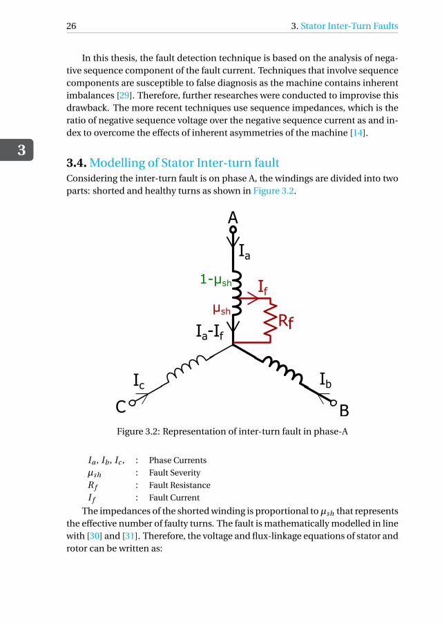
3.4. Modelling of Stator Inter-turn faultConsidering the inter-turn fault is on phase A, the windings are divided into twoparts: shorted and healthy turns as shown in Figure 3.2.
A
C B
Rf
Ia
Ic Ib
If
Ia-If
μsh
1-μsh
Figure 3.2: Representation of inter-turn fault in phase-A
Ia , Ib , Ic , : Phase Currents
µsh : Fault Severity
R f : Fault Resistance
I f : Fault Current
The impedances of the shorted winding is proportional toµsh that representsthe effective number of faulty turns. The fault is mathematically modelled in linewith [30] and [31]. Therefore, the voltage and flux-linkage equations of stator androtor can be written as:
3.4. Modelling of Stator Inter-turn fault
3
27
V sabc = Rs
(i s
abc −µabc I f)+ dλs
abc
dt
V rabc = Rr i r
abc +dλr
abc
dt
R f i f = Rsµsh(i s
a − i f)+ dλsh
a
dt
(3.1)
λsabc = Ls
(i s
abc −µabc i f)+Lmi r
abc
λrabc = Lm
(i s
abc −µabc i f)+Lmi r
abc
(3.2)
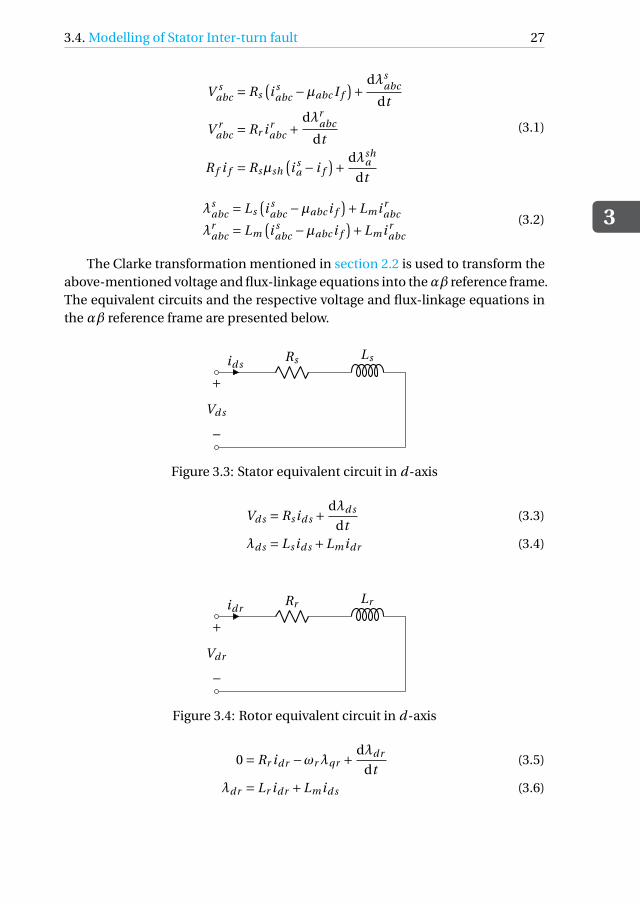
The Clarke transformation mentioned in section 2.2 is used to transform theabove-mentioned voltage and flux-linkage equations into theαβ reference frame.The equivalent circuits and the respective voltage and flux-linkage equations inthe αβ reference frame are presented below.
id sRs Ls
+
−Vd s
Figure 3.3: Stator equivalent circuit in d-axis
Vd s = Rs id s +dλd s
dt(3.3)
λd s = Ls id s +Lmidr (3.4)
idrRr Lr
+
−Vdr
Figure 3.4: Rotor equivalent circuit in d-axis
0 = Rr idr −ωrλqr + dλdr
dt(3.5)
λdr = Lr idr +Lmid s (3.6)
3
28 3. Stator Inter-Turn Faults
iqr Rr Lr
+
−Vqr
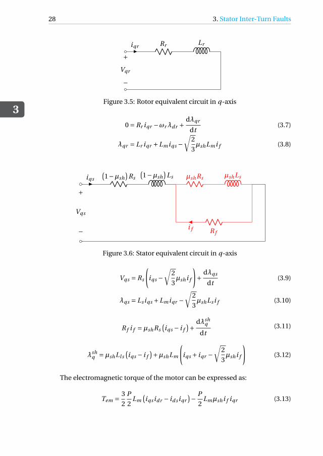
Figure 3.5: Rotor equivalent circuit in q-axis
0 = Rr iqr −ωrλdr +dλqr
dt(3.7)
λqr = Lr iqr +Lmiqs −√
2
3µshLmi f (3.8)
iqs
(1−µsh
)Rs
(1−µsh
)Ls µshRs µshLs
R fi f
+
−
Vqs
Figure 3.6: Stator equivalent circuit in q-axis
Vqs = Rs
(iqs −
√2
3µshi f
)+ dλqs
dt(3.9)
λqs = Ls iqs +Lmiqr −√
2
3µshLs i f (3.10)
R f i f =µshRs(iqs − i f
)+ dλshq
dt(3.11)
λshq =µshLl s
(iqs − i f
)+µshLm
(iqs + iqr −
√2
3µshi f
)(3.12)
The electromagnetic torque of the motor can be expressed as:
Tem = 3
2
P
2Lm
(iqs idr − id s iqr
)− P
2Lmµshi f iqr (3.13)
3.5. Operation of the Developed Model
3
29
3.5. Operation of the Developed ModelAccording to the datasheet of the motor, its starting time is 10 seconds. Since, thestart up performance of the motor falls out of scope in this work, the moment ofinertia is scaled down by a factor of 10 during startup to achieve steady-statefaster. The different operating conditions of the motor are:
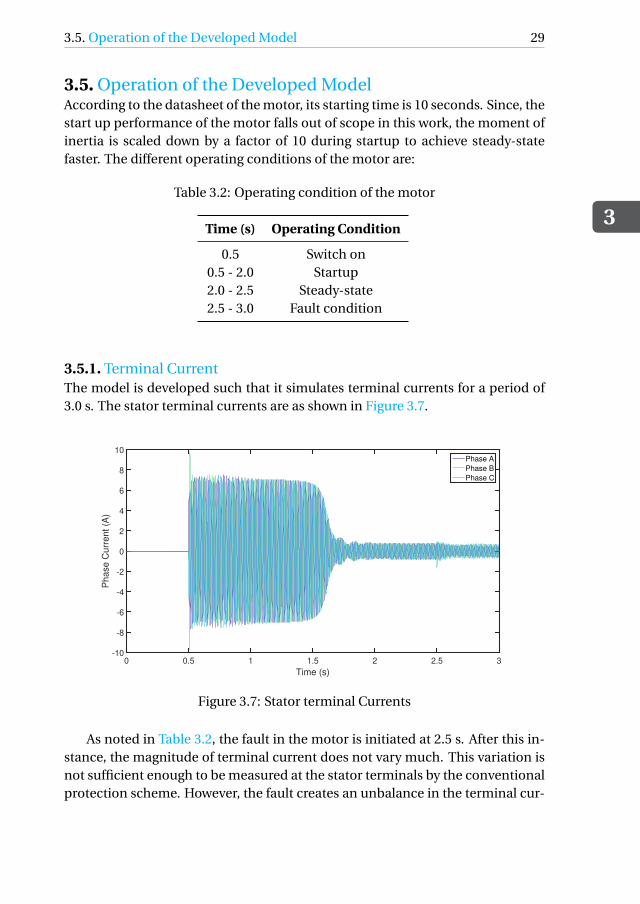
3.5.1. Terminal CurrentThe model is developed such that it simulates terminal currents for a period of3.0 s. The stator terminal currents are as shown in Figure 3.7.
0 0.5 1 1.5 2 2.5 3
Time (s)
-10
-8
-6
-4
-2
0
2
4
6
8
10
Ph
ase
Cu
rre
nt
(A)
Phase A
Phase B
Phase C
Figure 3.7: Stator terminal Currents
As noted in Table 3.2, the fault in the motor is initiated at 2.5 s. After this in-stance, the magnitude of terminal current does not vary much. This variation isnot sufficient enough to be measured at the stator terminals by the conventionalprotection scheme. However, the fault creates an unbalance in the terminal cur-
3
30 3. Stator Inter-Turn Faults
rents that gives rise to negative sequence component. The symmetrical com-ponents of voltages and currents can be used for detection of this fault. Suchimbalances also occur during the motor start-up. Therefore, proper differentia-tion is necessary to distinguish the two types of negative sequence componentsto avoid false trips.
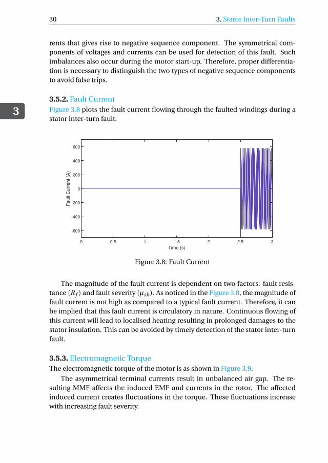
3.5.2. Fault CurrentFigure 3.8 plots the fault current flowing through the faulted windings during astator inter-turn fault.
0 0.5 1 1.5 2 2.5 3
Time (s)
-600
-400
-200
0
200
400
600
Fa
ult C
urr
en
t (A
)
Figure 3.8: Fault Current
The magnitude of the fault current is dependent on two factors: fault resis-tance (R f ) and fault severity (µsh). As noticed in the Figure 3.8, the magnitude offault current is not high as compared to a typical fault current. Therefore, it canbe implied that this fault current is circulatory in nature. Continuous flowing ofthis current will lead to localised heating resulting in prolonged damages to thestator insulation. This can be avoided by timely detection of the stator inter-turnfault.
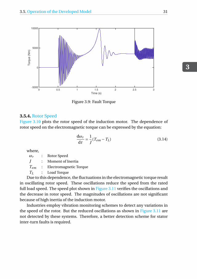
3.5.3. Electromagnetic TorqueThe electromagnetic torque of the motor is as shown in Figure 3.9.
The asymmetrical terminal currents result in unbalanced air gap. The re-sulting MMF affects the induced EMF and currents in the rotor. The affectedinduced current creates fluctuations in the torque. These fluctuations increasewith increasing fault severity.
3.5. Operation of the Developed Model
3
31
0 0.5 1 1.5 2 2.5 3
Time (s)
-5000
0
5000
10000T
orq
ue
(N
m)
Figure 3.9: Fault Torque
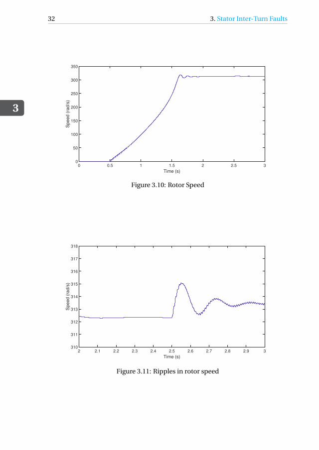
3.5.4. Rotor SpeedFigure 3.10 plots the rotor speed of the induction motor. The dependence ofrotor speed on the electromagnetic torque can be expressed by the equation:
dωr
dt= 1
J(Tem −TL) (3.14)
where,ωr : Rotor Speed
J : Moment of Inertia
Tem : Electromagnetic Torque
TL : Load TorqueDue to this dependence, the fluctuations in the electromagnetic torque result
in oscillating rotor speed. These oscillations reduce the speed from the ratedfull load speed. The speed plot shown in Figure 3.11 verifies the oscillations andthe decrease in rotor speed. The magnitudes of oscillations are not significantbecause of high inertia of the induction motor.
Industries employ vibration monitoring schemes to detect any variations inthe speed of the rotor. But the reduced oscillations as shown in Figure 3.11 arenot detected by these systems. Therefore, a better detection scheme for statorinter-turn faults is required.
3
32 3. Stator Inter-Turn Faults
0 0.5 1 1.5 2 2.5 3
Time (s)
0
50
100
150
200
250
300
350S
pe
ed
(ra
d/s
)
Figure 3.10: Rotor Speed
2 2.1 2.2 2.3 2.4 2.5 2.6 2.7 2.8 2.9 3
Time (s)
310
311
312
313
314
315
316
317
318
Sp
ee
d (
rad
/s)
Figure 3.11: Ripples in rotor speed
4Protection of the Machine
4.1. Protection DevicesElectrical equipment in a system may face intolerable conditions that can lead tofailure of the responsible and neighbouring equipment. These conditions maybe caused by natural phenomena such as lightning, or acts of human. Therefore,protective devices must be installed to ensure the reliability of the power system.They also limit the damage to the equipment preventing further progression ofthe fault.
Protective devices such as relays are compact intelligent electronic devicesconnected in different parts of a network to detect any abnormal operating con-dition. They monitor a defined signal which determines the state of system, andoperate according to the settings of the device. They operate based on limits seton measured quantities such as voltage, current, current direction, power factor,power, impedances, temperature.
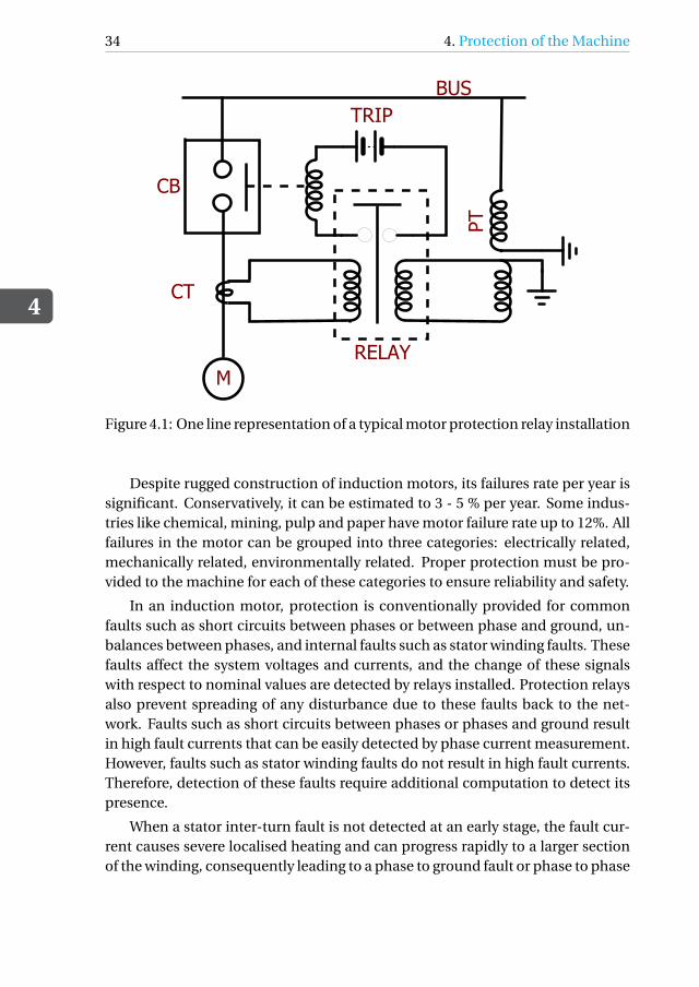
4.2. Principle of Motor ProtectionEvery machine is designed for specific operating conditions depending on therequirement and the functionality. When a machine exceeds these limits, it canlead to failure. Relays for motors are predominantly used in industries where thecost of replacement and maintenance of machines is higher than installation ofprotection relays. The schematic representation of a relay connection in a powersystem is as shown in Figure 4.1
where:CB : Circuit Breaker
CT : Current Transformer
PT : Potential Transformer
33
4
34 4. Protection of the Machine
TRIPBUS
PT
RELAY
CT
M
CB
Figure 4.1: One line representation of a typical motor protection relay installation
Despite rugged construction of induction motors, its failures rate per year issignificant. Conservatively, it can be estimated to 3 - 5 % per year. Some indus-tries like chemical, mining, pulp and paper have motor failure rate up to 12%. Allfailures in the motor can be grouped into three categories: electrically related,mechanically related, environmentally related. Proper protection must be pro-vided to the machine for each of these categories to ensure reliability and safety.
In an induction motor, protection is conventionally provided for commonfaults such as short circuits between phases or between phase and ground, un-balances between phases, and internal faults such as stator winding faults. Thesefaults affect the system voltages and currents, and the change of these signalswith respect to nominal values are detected by relays installed. Protection relaysalso prevent spreading of any disturbance due to these faults back to the net-work. Faults such as short circuits between phases or phases and ground resultin high fault currents that can be easily detected by phase current measurement.However, faults such as stator winding faults do not result in high fault currents.Therefore, detection of these faults require additional computation to detect itspresence.
When a stator inter-turn fault is not detected at an early stage, the fault cur-rent causes severe localised heating and can progress rapidly to a larger sectionof the winding, consequently leading to a phase to ground fault or phase to phase
4.3. GE Multilin 869 Motor Protection Relay
4
35
fault. This forces the machine out of service and increases the downtime. In thisproject, GE Multilin 869 Motor Protection relay is considered to detect the pres-ence of stator inter-turn fault.
4.3. GE Multilin 869 Motor Protection RelayThe GE Multilin 869 relay is a microprocessor based relay designed for protec-tion of synchronous and asynchronous machines. This relay comprises of manynovel features to match up to the industry standards and requirements. The fea-tures can be programmed individually to meet the user’s needs. A brief list of allthe functions available in the relay is as follows [32]:
• Motor Protection:
– Differential
– Thermal
– Current Unbalance
– Voltage Unbalance
– Short Circuit
– Overload
– Ground Faults
• Synchronous Motor Protection:
– Field Under/Over Current
– Field Under/Over Voltage
– SC Speed-Dependent Thermal
• 2-Speed Motor protection:
– 2-Speed Thermal
– 2-Speed Acceleration
– 2-Speed Undercurrent
• Current Protection:
– Phase/Neutral/Ground Time Over current
– Phase/Neutral/Ground Instantaneous Over current
– Phase/Neutral/Ground Directional Over current
• Voltage Protection:
4
36 4. Protection of the Machine
– Phase reversals
– Under/Over voltages
– Auxiliary Under/Over voltages
• Impedance protection
• Power:
– Directional Power
– Reactive Power
• Frequency Protection:
– Under/Over Frequency
– Rate of change of frequency
Relay setpoints are defined based on the information from the motor datasheets.If these information is unavailable, default values can be set for some functionsduring the commissioning.
The programming of these functions can be either be executed with the frontpanel keys and display screen on the relay or with a more interactive softwarecalled EnerVista 8 series Setup on a computer system. The software has two modesof working: online and offline. The online mode lets the user apply changes tothe setpoints in real time whereas the offline mode allows to save relay settingsin a file that can be uploaded to the relay at an later time.
4.4. Working Principle of the RelayThe Multilin 869 relay uses sequence components to provide advanced detectionof stator inter-turn faults. A brief summary of sequence components is presentedin Appendix A.
4.4.1. Methodology of OperationThe algorithm adopted in the relay can help detect an inter-turn fault before itprogresses to insulation breakdown, reducing the unplanned downtime of thesystem.
In steady state, the sequence component voltage equation is given in Equa-tion 4.1 [
V1
V2
]=
[Zpp Zpn
Znp Znn
][I1
I2
](4.1)
where,
4.4. Working Principle of the Relay
4
37
V1, V2 : Positive and Negative sequence voltages
I1, I2 : Positive and Negative sequence currents
Zpp , Znn : Positive and Negative sequence impedances
Znp , Zpn :Cross-coupled negative to positive/positive to negative sequenceimpedances.
In a symmetrical situation, the cross-coupled sequence impedances are zeroimplying that the positive and negative sequence components of the machineare decoupled. However, in practice, due to presence of inherent asymmetry inthe circuit, the cross-coupled sequences impedances have a small value. Theoccurrence of a stator inter-turn fault further aggravates these values. The stan-dardised ratio of cross-coupled impedances is an essential part in determiningthe operating condition of the relay. This ratio can be computed from the matrixgiven in Equation 4.1 and is given as [32]:
Znp
Zpp= V2 −Znn I2
V1
The default value of the unbalanced impedance (ZU Bbase ) is due to the in-herent asymmetry in the machine and can be defined as [32]:
ZU Bbase =(
Znp
Zpp
)at 0 inter-turn fault
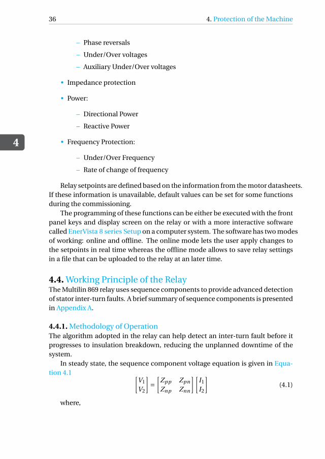
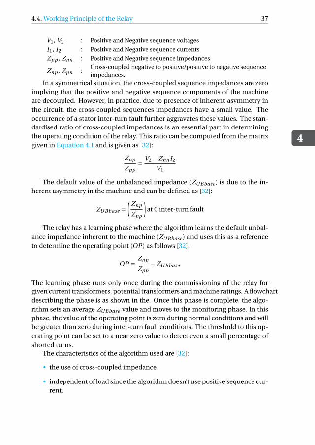
The relay has a learning phase where the algorithm learns the default unbal-ance impedance inherent to the machine (ZU Bbase ) and uses this as a referenceto determine the operating point (OP ) as follows [32]:
OP = Znp
Zpp−ZU Bbase
The learning phase runs only once during the commissioning of the relay forgiven current transformers, potential transformers and machine ratings. A flowchartdescribing the phase is as shown in the. Once this phase is complete, the algo-rithm sets an average ZU Bbase value and moves to the monitoring phase. In thisphase, the value of the operating point is zero during normal conditions and willbe greater than zero during inter-turn fault conditions. The threshold to this op-erating point can be set to a near zero value to detect even a small percentage ofshorted turns.
The characteristics of the algorithm used are [32]:
• the use of cross-coupled impedance.
• independent of load since the algorithm doesn’t use positive sequence cur-rent.
4
38 4. Protection of the Machine
START
DETERMINE Znn
OBTAIN VA, VB, VC, and IA, IB, IC
COMPUTE VAB, VBC, VCA
RUN GENERIC SIGNAL PROCESSING TO OBTAIN
PHASORS
COMPUTE V1, V2, and I2
DETERMINE Znp/Zpp
AVERAGE Znp/Zpp OVER Tavg
DONE ?
NO
SET
ZUBBase = Znp/Zpp
YES
GO TO MONITORING
PHASE
Figure 4.2: Flowchart describing the learning phase [33]
4.4. Working Principle of the Relay
4
39
START
DETERMINE Znn
OBTAIN VA, VB, VC, and IA, IB, IC
COMPUTE VAB, VBC, VCA
RUN GENERIC SIGNAL PROCESSING TO OBTAIN
PHASORS
COMPUTE V1, V2, and I2
DETERMINE Znp/Zpp
AVERAGE Znp/Zpp OVER Tavg
DONE ?
NO
COMPUTE
OP = Znp/Zpp - ZUBBase
YES
IS OP > TH 1
IS OP > TH 2
SET ALARM 1
SET ALARM 2
YES
YES
NO
NO
Figure 4.3: Flowchart describing the monitoring phase [33]
4
40 4. Protection of the Machine
• unaltered to system voltage unbalance: any unbalance in the system volt-age gives rise to negative sequence component in voltage and subsequentlyin current. But these negative sequence components are different from thethe ones generated due to the fault. The algorithm compensates the effectof any form of unbalance in the system.
• independent of machine ratings: the cross-coupled sequence impedancesare machine parameters, therefore machine dependent. But the normali-sation of those values with respect to its own base positive sequence impedancemakes them independent of machine ratings.
• the algorithm is insensitive to errors in measurement.
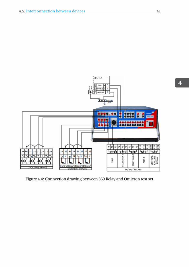
4.5. Interconnection between devicesThe Omicron Universal relay test set employs multiple analog and digital ports.Figure 4.4 shows the front panel of the test set.
The relay requires 110 V to power up and make a trip contact. The auxiliaryDC supply of omicron test set provides this. The Omicron CMC 356 test set hasfour voltage and six current output channels that can continuously regulate theamplitude, phase and frequency of the signals. All the output channels are pro-tected against over-heating, external transients and overloads. The trip eventsare recorded by the omicron set up using one of the binary output channels. Theexperimental test set up for GE multilin relay is as shown in the figure.
The secondary voltage and current signals are fed into the relay by connect-ing to these voltage and current output ports. The omicron test set has two cur-rent outputs that are generally used for differential protection. However, in thiscase, only one of the current output ports is required. Therefore, the two sets ofoutput ports are shorted manually.
The wiring drawing representing the connections between the relay and theOmicron test set up is shown below:
4.5. Interconnection between devices
4
41
Figure 4.4: Connection drawing between 869 Relay and Omicron test set.
5Testing of the Relay
The crucial functions of protection relay requires confidence in its operation.The reliability of the relay can be assured by performing tests during its com-missioning and scheduled maintenance. Along with a reliability check, regulartesting can ensure correct operation of the protection relay during a fault condi-tion. With ageing of the machines, regular testings can also help in optimisationof relay settings to synchronise the protection.
Testing of numerical relays can be done in two ways [34]:
• Primary Injection Testing: These tests involve a complete working circuit:a current transformer, relay, trip alarm and all wiring. These type of testingis generally performed during the commissioning of the relay or protectivedevice.
• Secondary Injection Testing: The purpose of this type of testing is similar toprimary injection testing. However, these use a relay test set that can sim-ulate various levels of voltage and current to verify proper relay responseas per setting. These type of testing can be performed in a laboratory envi-ronment.
The drawback of a primary injection testing is that the test up is expensiveand the process is time consuming. Application of faults in the system will affectthe remaining network. Therefore, the secondary injection testing type is usedhere. The testing of the Multilin 869 Relay is done using Omicron CMC 356.
5.1. Procedure of TestingThe output waveforms of EMTP-ATP simulations are saved in ".CFG" or COM-TRADE format. COMTRADE stands for Common format for Transient Data Exchange.
43
5
44 5. Testing of the Relay
The ".CFG" file stores sampled data relevant to transients or power system distur-bances. With Omicron CMC, ".CFG" files are compatible. Therefore, the outputfiles are directly saved in this format. The .CFG files store the signal names, units,maximum and minimum values of all the signals, number of samples and timeof simulation. The ".DAT" file stores all the data sampled at 10−4 Hz.
The .CFG files are then uploaded to Advanced transplay module of Omicronand can be tested directly after all the connections between Omicron and therelay module is secured. For testing purpose, the motor start-up is ignored andonly steady state and fault condition is considered.
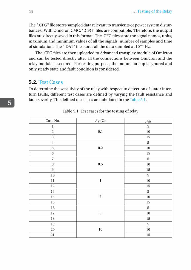
5.2. Test CasesTo determine the sensitivity of the relay with respect to detection of stator inter-turn faults, different test cases are defined by varying the fault resistance andfault severity. The defined test cases are tabulated in the Table 5.1.
Table 5.1: Test cases for the testing of relay
Case No. R f (Ω) µsh
1
0.1
5
2 10
3 15
4
0.2
5
5 10
6 15
7
0.5
5
8 10
9 15
10
1
5
11 10
12 15
13
2
5
14 10
15 15
16
5
5
17 10
18 15
19
10
5
20 10
21 15
5.2. Test Cases
5
45
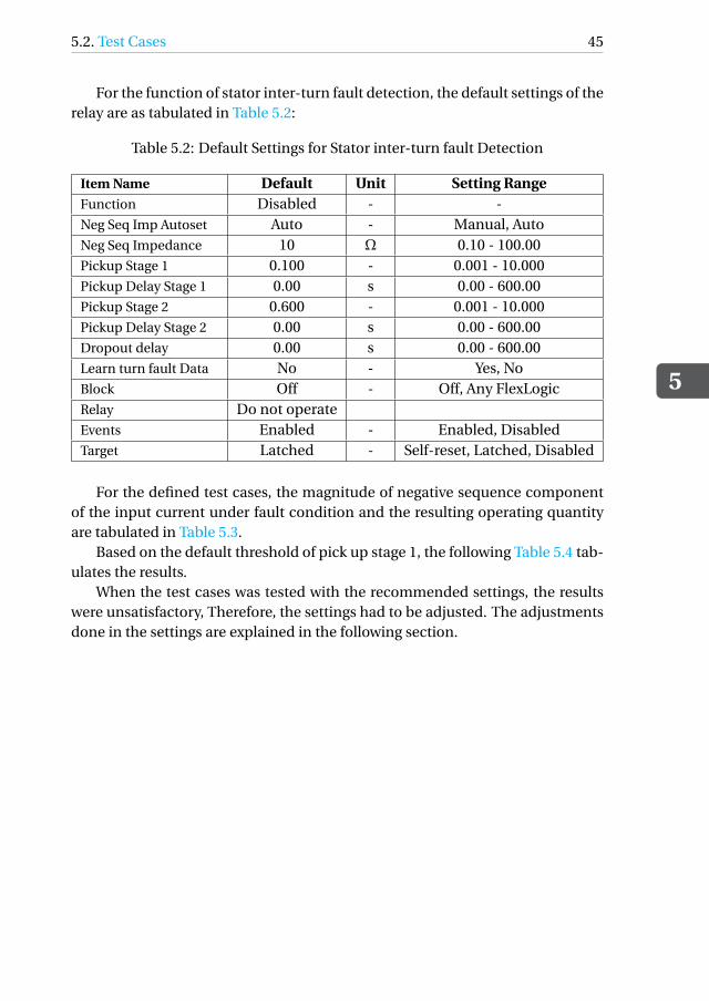
For the function of stator inter-turn fault detection, the default settings of therelay are as tabulated in Table 5.2:
Table 5.2: Default Settings for Stator inter-turn fault Detection
Item Name Default Unit Setting RangeFunction Disabled - -Neg Seq Imp Autoset Auto - Manual, AutoNeg Seq Impedance 10 Ω 0.10 - 100.00Pickup Stage 1 0.100 - 0.001 - 10.000Pickup Delay Stage 1 0.00 s 0.00 - 600.00Pickup Stage 2 0.600 - 0.001 - 10.000Pickup Delay Stage 2 0.00 s 0.00 - 600.00Dropout delay 0.00 s 0.00 - 600.00Learn turn fault Data No - Yes, NoBlock Off - Off, Any FlexLogicRelay Do not operateEvents Enabled - Enabled, DisabledTarget Latched - Self-reset, Latched, Disabled
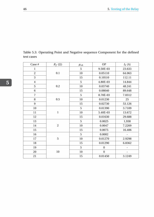
For the defined test cases, the magnitude of negative sequence componentof the input current under fault condition and the resulting operating quantityare tabulated in Table 5.3.
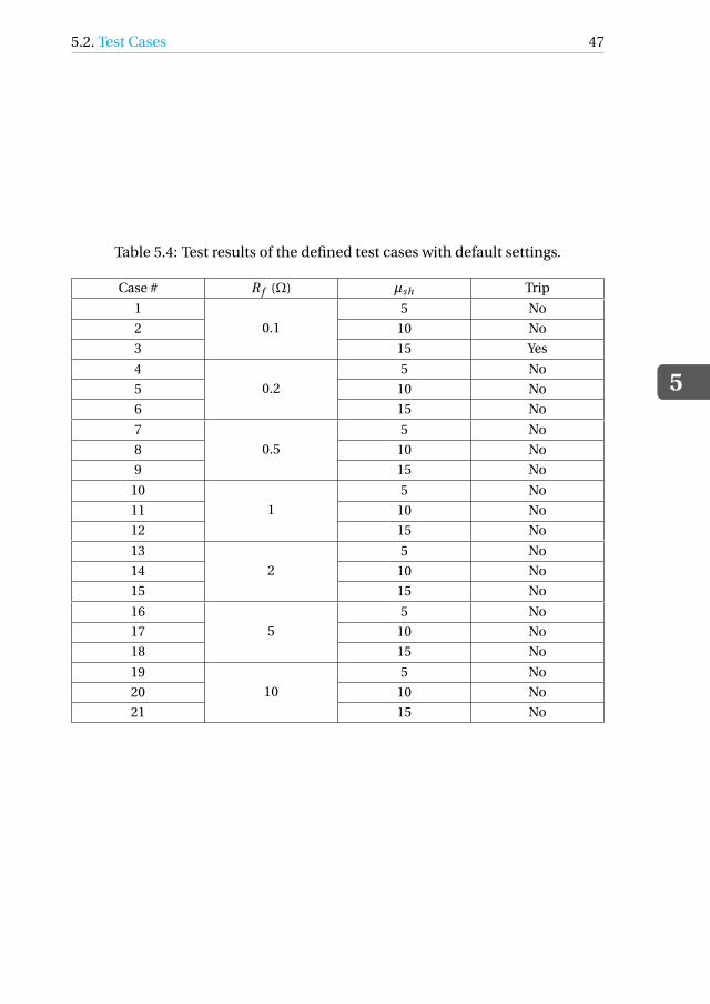
Based on the default threshold of pick up stage 1, the following Table 5.4 tab-ulates the results.
When the test cases was tested with the recommended settings, the resultswere unsatisfactory, Therefore, the settings had to be adjusted. The adjustmentsdone in the settings are explained in the following section.
5
46 5. Testing of the Relay
Table 5.3: Operating Point and Negative sequence Component for the definedtest cases
Case # R f (Ω) µsh OP I2 (A)
1
0.1
5 9.50E-03 23.633
2 10 0.05110 64.063
3 15 0.10510 112.11
4
0.2
5 4.80E-03 14.844
5 10 0.03740 48.241
6 15 0.08040 89.648
7
0.5
5 8.70E-03 7.0312
8 10 0.01230 25
9 15 0.02730 53.126
10
1
5 0.01390 3.7109
11 10 5.40E-03 13.672
12 15 0.01630 29.688
13
2
5 0.0025 1,938
14 10 0.0047 7.2269
15 15 0.0075 16.406
16
5
5 0.0002 -
17 10 0.01270 2.9298
18 15 0.01290 6.8362
19
10
5 0 -
20 10 0 -
21 15 0.01450 3.1249
5.2. Test Cases
5
47
Table 5.4: Test results of the defined test cases with default settings.
Case # R f (Ω) µsh Trip
1
0.1
5 No
2 10 No
3 15 Yes
4
0.2
5 No
5 10 No
6 15 No
7
0.5
5 No
8 10 No
9 15 No
10
1
5 No
11 10 No
12 15 No
13
2
5 No
14 10 No
15 15 No
16
5
5 No
17 10 No
18 15 No
19
10
5 No
20 10 No
21 15 No
5
48 5. Testing of the Relay
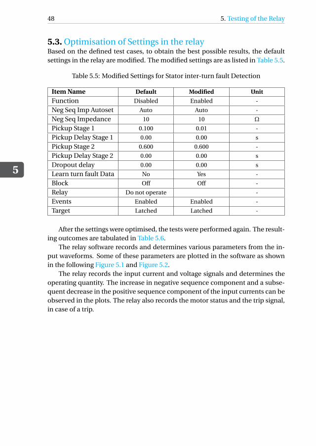
5.3. Optimisation of Settings in the relayBased on the defined test cases, to obtain the best possible results, the defaultsettings in the relay are modified. The modified settings are as listed in Table 5.5.
Table 5.5: Modified Settings for Stator inter-turn fault Detection
Item Name Default Modified Unit
Function Disabled Enabled -
Neg Seq Imp Autoset Auto Auto -
Neg Seq Impedance 10 10 Ω
Pickup Stage 1 0.100 0.01 -
Pickup Delay Stage 1 0.00 0.00 s
Pickup Stage 2 0.600 0.600 -
Pickup Delay Stage 2 0.00 0.00 s
Dropout delay 0.00 0.00 s
Learn turn fault Data No Yes -
Block Off Off -
Relay Do not operate -
Events Enabled Enabled -
Target Latched Latched -
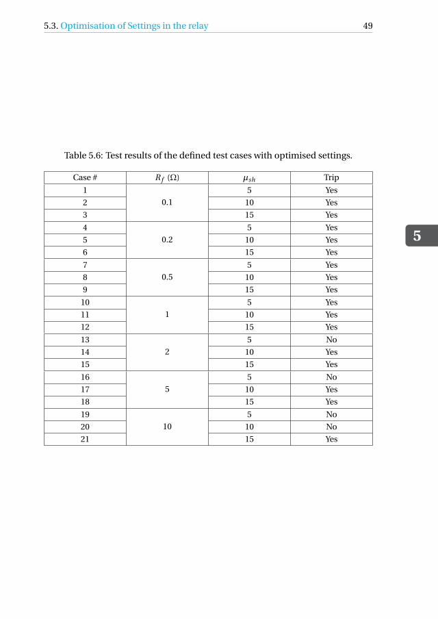
After the settings were optimised, the tests were performed again. The result-ing outcomes are tabulated in Table 5.6.
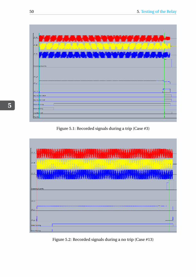
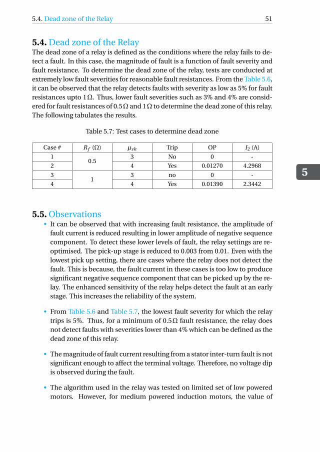
The relay software records and determines various parameters from the in-put waveforms. Some of these parameters are plotted in the software as shownin the following Figure 5.1 and Figure 5.2.
The relay records the input current and voltage signals and determines theoperating quantity. The increase in negative sequence component and a subse-quent decrease in the positive sequence component of the input currents can beobserved in the plots. The relay also records the motor status and the trip signal,in case of a trip.
5.3. Optimisation of Settings in the relay
5
49
Table 5.6: Test results of the defined test cases with optimised settings.
Case # R f (Ω) µsh Trip
1
0.1
5 Yes
2 10 Yes
3 15 Yes
4
0.2
5 Yes
5 10 Yes
6 15 Yes
7
0.5
5 Yes
8 10 Yes
9 15 Yes
10
1
5 Yes
11 10 Yes
12 15 Yes
13
2
5 No
14 10 Yes
15 15 Yes
16
5
5 No
17 10 Yes
18 15 Yes
19
10
5 No
20 10 No
21 15 Yes
5
50 5. Testing of the Relay
Figure 5.1: Recorded signals during a trip (Case #3)
Figure 5.2: Recorded signals during a no trip (Case #13)
5.4. Dead zone of the Relay
5
51
5.4. Dead zone of the RelayThe dead zone of a relay is defined as the conditions where the relay fails to de-tect a fault. In this case, the magnitude of fault is a function of fault severity andfault resistance. To determine the dead zone of the relay, tests are conducted atextremely low fault severities for reasonable fault resistances. From the Table 5.6,it can be observed that the relay detects faults with severity as low as 5% for faultresistances upto 1Ω. Thus, lower fault severities such as 3% and 4% are consid-ered for fault resistances of 0.5Ω and 1Ω to determine the dead zone of this relay.The following tabulates the results.
Table 5.7: Test cases to determine dead zone
Case # R f (Ω) µsh Trip OP I2 (A)
10.5
3 No 0 -
2 4 Yes 0.01270 4.2968
31
3 no 0 -
4 4 Yes 0.01390 2.3442
5.5. Observations• It can be observed that with increasing fault resistance, the amplitude of
fault current is reduced resulting in lower amplitude of negative sequencecomponent. To detect these lower levels of fault, the relay settings are re-optimised. The pick-up stage is reduced to 0.003 from 0.01. Even with thelowest pick up setting, there are cases where the relay does not detect thefault. This is because, the fault current in these cases is too low to producesignificant negative sequence component that can be picked up by the re-lay. The enhanced sensitivity of the relay helps detect the fault at an earlystage. This increases the reliability of the system.
• From Table 5.6 and Table 5.7, the lowest fault severity for which the relaytrips is 5%. Thus, for a minimum of 0.5Ω fault resistance, the relay doesnot detect faults with severities lower than 4% which can be defined as thedead zone of this relay.
• The magnitude of fault current resulting from a stator inter-turn fault is notsignificant enough to affect the terminal voltage. Therefore, no voltage dipis observed during the fault.
• The algorithm used in the relay was tested on limited set of low poweredmotors. However, for medium powered induction motors, the value of
5
52 5. Testing of the Relay
the operating point may increase when connected to a unbalanced volt-age supply. Therefore, the relay has a wide range of settings.
• The learning of ZU Bbase also impacts wide range of settings. This impedancecan only be learnt either during the commissioning or the installation of arecently repaired motor. However, in existing installations, the determi-nation of ZU Bbase is not possible. Therefore, the relay can consider it tobe zero and Znp/Zpp will have a higher value to accommodate the inherentasymmetry of the machine.
• Few other factors affecting the wide range of settings are motor ratings,unbalance from the system, inherent asymmetries of the motor, fault dy-namics affecting the negative sequence impedance of the motor.
6Conclusion
The conventional protection system in use, fails to detect stator inter-turn faultsat an early stage. Without early detection, the fault further aggravates into drasticfaults such as phase faults. Therefore, a timely detection of such faults becomesa key point of focus. In this thesis, research on stator inter-turn faults and relaysprotecting against it was conducted.
• Chapter 1 gave an introduction to the objectives and motivation of the the-sis. It described the problem in focus and the scope of work.
• Chapter 2 described the working principle of an induction machine, itsvoltage equations and different methods to model it. An introduction totransformation theory and its necessity in modelling rotary machines wasdiscussed. This thesis employed Clarke’s transformation to reduce the com-putational complexity in the model by transforming the three phase quan-tities to two phase quantities. The induction machine was modelled us-ing the dynamic voltage and torque equations based on these transformedquantities. The latter part of this chapter explained the choice of platform(EMTP-ATP) for modelling and simulation of the machine along with thefault. A validation model was built with default elements to verify the de-veloped model.
• Chapter 3 explained the typical causes and consequences of stator inter-turn faults in an induction motor. Existing methods to detect such faultswere presented. Thereafter, modelling of stator inter-turn fault in the in-duction motor was described.
53
6
54 6. Conclusion
• Chapter 4 gave insight to the principles of motor protection, protectionrelays and their necessity. The GE Multilin 869 motor protection relay usedin this thesis was introduced. The working algorithm used in the relay fordetection of a stator inter-turn fault, the parameters used by the relay, andthe interconnection with secondary testing kit were also discussed.
• Chapter 5 explained the testing procedure of the relay and listed out thetest cases generated for the stated problem. Based on the finalised testcases, the optimisation of relay settings were explained. Furthermore, thischapter also recorded the dead zone of the relay beyond which the relaycannot detect the fault.
This thesis intended to answer the research questions asked at the beginningof this thesis.
1. How can an induction machine be modelled accurately to detect statorinter-turn fault?
The dynamic modelling of stator inter-turn fault in an induction motor wasdeveloped in MODELS environment of EMTP’s ATPDraw. This thesis em-ployed Clarke’s transformation to reduce the computational complexity inthe model by transforming the three phase quantities to two phase quanti-ties. The non-idealities involved in the machine and fault modelling wereaverted by considering different assumptions. For example, assumptionsconsidered for the progression of fault and fault resistances do not havesubstantial amount of research. However, due diligence has been done byconsidering industry data in this area.
2. How can the fault current resulting from a stator inter-turn fault be de-tected considering its low magnitude?
In this thesis, a medium power induction motor used in a chemical indus-try was considered. A stator inter-turn fault with varying severities wereintroduced during the normal operation of this machine and the resultingcurrents were analysed. As expected, the magnitude of terminal currentsdid not have much variation after the occurrence of the fault. This is due tothe circulatory nature of the fault current. These low magnitude fault cur-rent create unbalances in the terminal current that can be used to detectan inter-turn fault.
3. What is the principle of stator inter-turn fault detection in the chosenprotection relay?
6.1. Discussion
6
55
Here, for detection, GE’s Multilin 869 motor protection relay is considered.This relay uses sequence cross-coupled impedance for advanced detectionof stator inter-turn faults. In an ideal balanced situation, the cross-coupledsequence impedances are zero implying that the positive and negative se-quence components of the machine are decoupled. However, in case of afault, these impedances have small values.These values are used to detectthe presence of a stator inter-turn fault.
4. What are the suitable settings in the chosen protection relay to detect theleast severe inter-turn fault without causing any false trips?
For the medium power motor in focus, the dead zone of the relay was de-termined. Based on this dead zone settings were changed from their de-fault values to ensure reliable detection of stator inter-turn faults.
6.1. DiscussionAfter extensive research, a few discussion point are are listed below:
1. The transformed dynamic model of the induction motor is derived basedon the power-invariant Clarke’s transformation. The model developed in[35] was taken as a reference. However, discrepancies in the performancecharacteristics were observed. These were resolved and the machine modelwas validated with the universal motor model in EMTP-ATP.
2. The detection of a stator inter-turn fault is a monitoring condition ratherthan a protection function in GE Multilin 869 motor protection relay. There-fore, in case of occurrence of the fault, the relay sends an alarm signal andnot a trip signal.
3. When the terminal currents transition from motor start-up to steady state,momentary unbalance occurs. These type of temporary unbalance can beseen during phenomena such as power dips or transfer operations. Theygive rise to negative sequence components that gets picked up by the Mul-tilin 869 relay. Therefore, the current output waveforms considered fortesting does not include motor start-up.
4. The range of settings provided in the relay are broad. The pick up quan-tity varies from 0.001 to 10.000. This makes the relay highly sensitive. Formedium power induction motors, the relay settings for detection of inter-turn fault are to be considered very close to the lower limit. This mightresult in false alarms.
6
56 6. Conclusion
5. The developed model does not include saturation of the current trans-formers as low fault currents of such magnitudes are not expected to satu-rate the transformer.
6. Industries employ vibration monitoring schemes to detect any variationsin the speed of the rotor. But the reduced oscillations due to high inertiaof the induction motor are not detected by these systems. Therefore, thedetection scheme employed by GE Multilin protection relay is required.
6.2. Enhancements proposed by GEBased on the work done in the thesis, GE has proposed the following enhance-ments to the relay:
1. The ’Data Quality Check’ feature is to be added in the next release. Thiswill help resolve false tripping occurring due to system input. This featurewill possibly check temporary power variations, unbalance introduced bythe system, frequency variation, and other possible asymmetries.
2. The wide range of settings is to be changed to lower levels assuming properlearning of ZU BB ase and Znn . This can be implemented only after the ’DataQuality Check’ feature is included in the relay.
6.3. Future workThis thesis presented a comprehensive method of detecting stator inter-turn faultsin induction motors. However, the model designed and the algorithm used fordetection have their own drawbacks. Therefore, considerable changes can beinculcated in order to achieve refined results. A few recommendations are pre-sented below based on the work presented.
1. Currently the designed model only considers the effect of stator inter-turnfaults on the given network. To further improve the reliability of the net-work, the model can be made voltage dependent and effect of operationssuch as power-dips, automatic transfer switching can be observed.
2. An interactive model can be developed that can replicate the progressionof an inter-turn fault into a phase-to-ground fault.
3. Algorithms can be included to predict the tripping of relay based on therelay settings.
4. In this thesis, the accuracy of potential core transformer is not considered.The effect of this accuracy on the highly sensitive algorithm can be ex-plored.
Bibliography
[1] P. Albrecht, J. Appiarius, R. McCoy, E. Owen, and D. Sharma, “Assessment ofthe reliability of motors in utility applications-updated,” IEEE Transactionson Energy conversion, no. 1, pp. 39–46, 1986.
[2] M. Drif and A. J. M. Cardoso, “Stator fault diagnostics in squirrel cage three-phase induction motor drives using the instantaneous active and reac-tive power signature analyses,” IEEE Transactions on Industrial Informat-ics, vol. 10, no. 2, pp. 1348–1360, 2014.
[3] L. Xiao, H. Sun, F. Gao, S. Hou, and L. Li, “A new diagnostic method forwinding short-circuit fault for srm based on symmetrical component anal-ysis,” Chinese Journal of Electrical Engineering, vol. 4, no. 1, pp. 74–82, 2018.
[4] L. Maraaba, Z. Al-Hamouz, and M. Abido, “An efficient stator inter-turnfault diagnosis tool for induction motors,” Energies, vol. 11, no. 3, p. 653,2018.
[5] S. Williamson and K. Mirzoian, “Analysis of cage induction motors withstator winding faults,” IEEE transactions on power apparatus and systems,no. 7, pp. 1838–1842, 1985.
[6] G. Kliman, W. Premerlani, R. Koegl, and D. Hoeweler, “A new approachto on-line turn fault detection in ac motors,” in IAS’96. Conference Recordof the 1996 IEEE Industry Applications Conference Thirty-First IAS AnnualMeeting, IEEE, vol. 1, 1996, pp. 687–693.
[7] X. Luo, Y. Liao, H. A. Toliyat, A. El-Antably, and T. A. Lipo, “Multiple cou-pled circuit modeling of induction machines,” IEEE Transactions on indus-try applications, vol. 31, no. 2, pp. 311–318, 1995.
[8] P. C. Krause, O. Wasynczuk, S. D. Sudhoff, and S. Pekarek, Analysis of electricmachinery and drive systems. Wiley Online Library, 2002, vol. 2.
[9] L. Dubé, “Users guide to models in atp,” Neskowin OR, 1996.
[10] L. Dubé, “How to use models-based user-defined network components inatp,” in EUROPEAN EMTP USERS GROUP MEETING, 1996, pp. 10–12.
[12] H. W. Penrose, “Test methods for determining the impact of motor condi-tion on motor efficiency and reliability,” ALL-TEST Pro, LLC, 2007.
57
6
58 Bibliography
[13] S. Grubic, J. M. Aller, B. Lu, and T. G. Habetler, “A survey on testing andmonitoring methods for stator insulation systems of low-voltage induc-tion machines focusing on turn insulation problems,” IEEE Transactionson Industrial Electronics, vol. 55, no. 12, pp. 4127–4136, 2008.
[14] A. Strandt, “Characterization of stator winding short-circuit faults in inte-rior permanent-magnet motor-drive systems,” 2013.
[15] A. Berzoy, A. Mohamed, and O. Mohammed, “Stator winding inter-turnfault in induction machines: Complex-vector transient and steady-statemodelling,” in 2017 IEEE International Electric Machines and Drives Con-ference (IEMDC), IEEE, 2017, pp. 1–7.
[16] P. Chen, Y. Xie, and S. Hu, “The effect of stator inter-turn short circuit faultson electromagnetic performances of induction motors,” in 2019 22nd In-ternational Conference on Electrical Machines and Systems (ICEMS), IEEE,2019, pp. 1–5.
[17] R. M. Tallam, S. B. Lee, G. C. Stone, G. B. Kliman, J. Yoo, T. G. Habetler, andR. G. Harley, “A survey of methods for detection of stator-related faults ininduction machines,” IEEE Transactions on Industry Applications, vol. 43,no. 4, pp. 920–933, 2007.
[18] M. Eftekhari, M. Moallem, S. Sadri, and A. Shojaei, “Review of inductionmotor testing and monitoring methods for inter-turn stator winding faults,”in 2013 21st Iranian Conference on Electrical Engineering (ICEE), IEEE, 2013,pp. 1–6.
[19] Y. B. Koca and A. Ünsal, “A review on detection and monitoring of statorfaults of induction motors,” International Journal of Innovative Researchin Science, Engineering and Technology (IJIRSET), vol. 6, no. 10, 2017.
[20] A. Glowacz and Z. Glowacz, “Diagnostics of stator faults of the single-phaseinduction motor using thermal images, moasos and selected classifiers,”Measurement, vol. 93, pp. 86–93, 2016.
[21] P. A. Delgado-Arredondo, D. Morinigo-Sotelo, R. A. Osornio-Rios, J. G. Avina-Cervantes, H. Rostro-Gonzalez, and R. de Jesus Romero-Troncoso, “Method-ology for fault detection in induction motors via sound and vibration sig-nals,” Mechanical Systems and Signal Processing, vol. 83, pp. 568–589, 2017.
[22] V. Hegde and G. Maruthi, “Experimental investigation on detection of airgap eccentricity in induction motors by current and vibration signatureanalysis using non-invasive sensors,” Energy Procedia, vol. 14, pp. 1047–1052, 2012.
Bibliography
6
59
[23] P. Lamim Filho, R. Pederiva, and J. Brito, “Detection of stator winding faultsin induction machines using flux and vibration analysis,” Mechanical Sys-tems and Signal Processing, vol. 42, no. 1-2, pp. 377–387, 2014.
[24] A. Siddique, G. Yadava, and B. Singh, “A review of stator fault monitoringtechniques of induction motors,” IEEE transactions on energy conversion,vol. 20, no. 1, pp. 106–114, 2005.
[25] S.-h. Lee, Y.-q. Wang, and J.-i. Song, “Fourier and wavelet transformationsapplication to fault detection of induction motor with stator current,” Jour-nal of Central South University of Technology, vol. 17, no. 1, pp. 93–101,2010.
[26] A. Allal and B. Chetate, “A new and best approach for early detection of ro-tor and stator faults in induction motors coupled to variable loads,” Fron-tiers in Energy, vol. 10, no. 2, pp. 176–191, 2016.
[27] M. Rajagopal, K. Seetharamu, and P. Ashwathnarayana, “Transient ther-mal analysis of induction motors,” IEEE transactions on energy conversion,vol. 13, no. 1, pp. 62–69, 1998.
[28] G. C. Stone, E. A. Boulter, I. Culbert, and H. Dhirani, Electrical insulationfor rotating machines: design, evaluation, aging, testing, and repair. JohnWiley & Sons, 2004, vol. 21.
[29] J. Sottile and J. L. Kohler, “An on-line method to detect incipient failure ofturn insulation in random-wound motors,” IEEE Transactions on EnergyConversion, vol. 8, no. 4, pp. 762–768, 1993.
[30] M. Wieczorek and E. Rosołowski, “Modelling of induction motor for sim-ulation of internal faults,” in 2010 Modern Electric Power Systems, IEEE,2010, pp. 1–6.
[31] R. M. Tallam, T. G. Habetler, and R. G. Harley, “Transient model for induc-tion machines with stator winding turn faults,” IEEE Transactions on In-dustry Applications, vol. 38, no. 3, pp. 632–637, 2002.
[33] P. Ostojic, A. Banerjee, D. C. Patel, W. Basu, and S. Ali, “Advanced motormonitoring and diagnostics,” IEEE Transactions on Industry Applications,vol. 50, no. 5, pp. 3120–3127, 2014.
[35] A. T. Saraswathi, “Testing of motor protection for internal faults,” 2016.
60 Bibliography
[36] C. L. Fortescue, “Method of symmetrical co-ordinates applied to the solu-tion of polyphase networks,” Transactions of the American Institute of Elec-trical Engineers, vol. 37, no. 2, pp. 1027–1140, 1918.
[37] R. S. Zhang, “High Performance Power Converter Systems for Nonlinearand Unbalanced Load/Source,” Doctoral Dissertation, Virgina Tech, Nov. 17,1998. [Online]. Available: http://hdl.handle.net/10919/29314 (vis-ited on 01/05/2021).
To understand the unbalanced behaviour of three-phase systems, three phasequantities can be transformed into symmetrical components, by using Fortes-cue transformation [36]. This transformation makes it easier to analyse the un-balanced systems. It also has physical interpretation associated with it [37]. In athree-phase network, the phase-currents I A , IB and IC are given as shown belowin Equation A.1: I A
IB
IC
=I A sin
(ωt−φA
)IB sin
(ωt−φB
)IC sin
(ωt−φC
) (A.1)
where ω is the angular frequency of the sinusoidal waveform and φA ,φB andφC represent the phase-difference with respect to the reference angle ωt.
In a balanced condition, the phasors have the same amplitude and are ex-actly 2π/3 rads apart. Thus, the system can be represented and analysed as anequivalent single-phase system and extrapolate it to the three-phase networks.
In unbalanced networks, the analysis becomes complex as the phasors havedifferent magnitudes and phase differences. To simplify this, Fortescue proposedto transform these three-phase unbalanced phasors into Positive, Negative andZero-Sequence Components [36]. The decomposition results in three-sets of bal-anced phasors. The transformation of line currents into their respective symmet-ric components is done as per the transformation in Equation A.2 [36]:I0
I1
I2
= 1
3
1 1 11 a a2
1 a2 a
I A
IB
IC
(A.2)
63
A
64 A. Symmetrical Components
where a = e j2π/3, and I1, I2 and I0 are the positive, negative and zero-sequencecomponents of the current respectively. Similarly, the inverse transformation isgiven in Equation A.3: I A
IB
IC
=1 1 1
1 a2 a1 a a2
I0
I1
I2
(A.3)
BDeveloped Model of Induction
Motor
The dynamic model of a induction motor with stator inter-turn fault developedusing EMTP-ATP is presented.