SOME DYNAMICS AND CONTROL CHALLENGES THAT OCCURED DURING THE APOLLO PROJECT William S. Widnall, ScD Formerly Director, Control and Flight Dynamics, M.I.T. Instrumentation Laboratory INTRODUCTION President Kennedy set the goal to put a man on the moon and return him safely before the end of the 60's decade. The M.I.T. Instrumentation Lab (now called the Draper Lab, in honor of its founder) was awarded by NASA the first prime contract -- a contract to develop the navigation, guidance, and control system for both the Command Module and the Lunar Module of the Apollo Spacecraft.
Transcript
SOME DYNAMICS AND CONTROL CHALLENGESTHAT OCCURED DURING THE APOLLO PROJECTWilliam S. Widnall, ScDFormerly Director, Control and Flight Dynamics,M.I.T. Instrumentation Laboratory
INTRODUCTION
President Kennedy set the goal to put a man on the moon and return him safely before the end of the 60's decade.
The M.I.T. Instrumentation Lab (now called the Draper Lab, in honor of its founder) was awarded by NASA the first prime contract -- a contract to develop the navigation, guidance, and control system for both the Command Module and the Lunar Module of the Apollo Spacecraft.
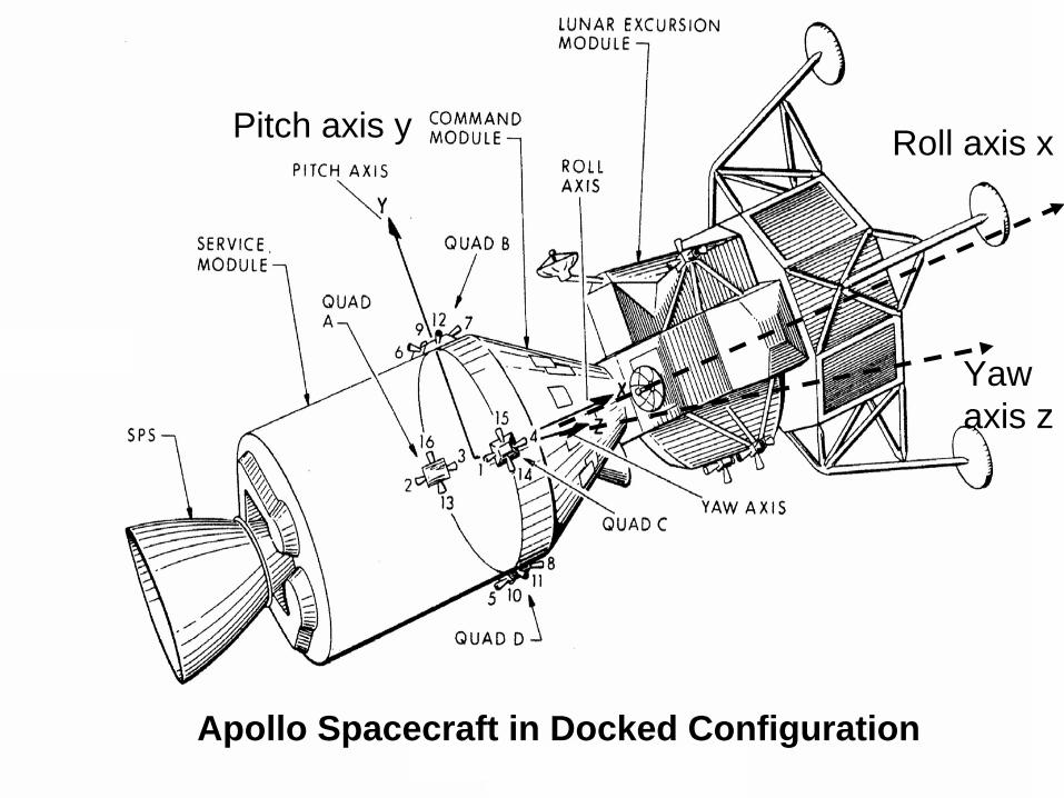
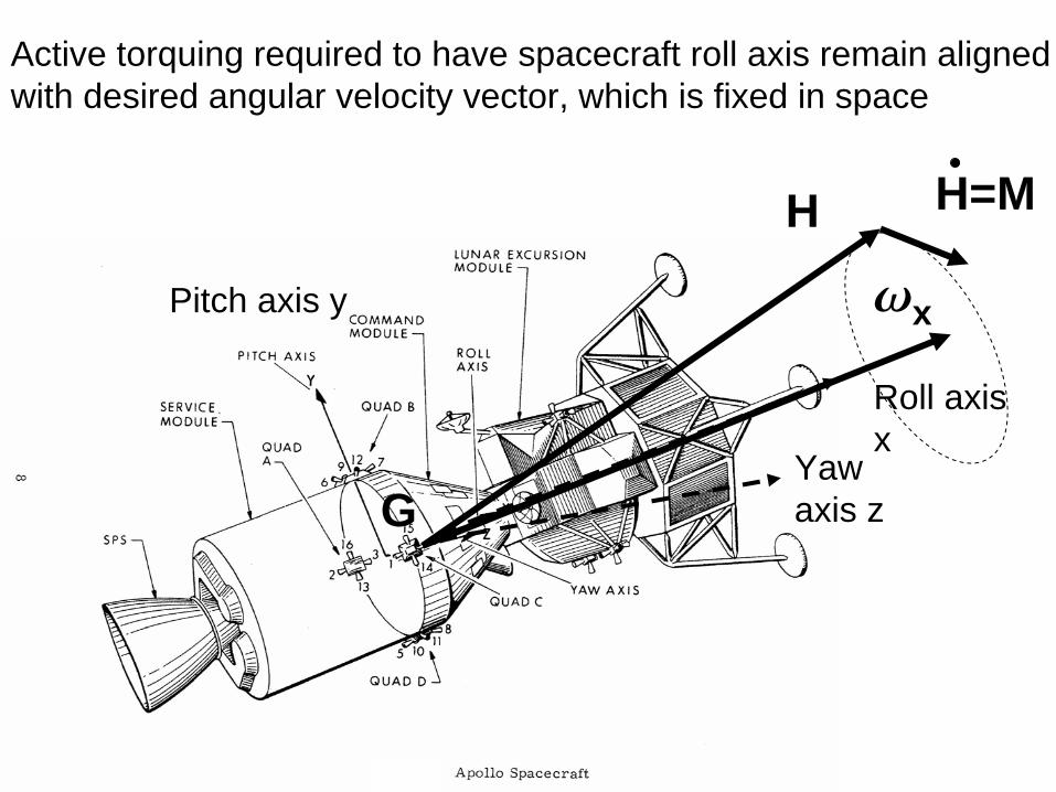
Yaw axis z
Roll axis xPitch axis y
Apollo Spacecraft in Docked Configuration
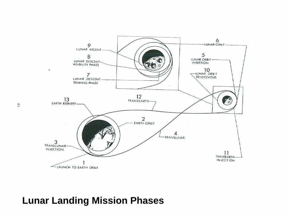
Lunar Landing Mission Phases
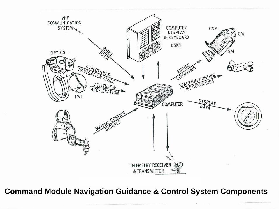
Command Module Navigation Guidance & Control System Components
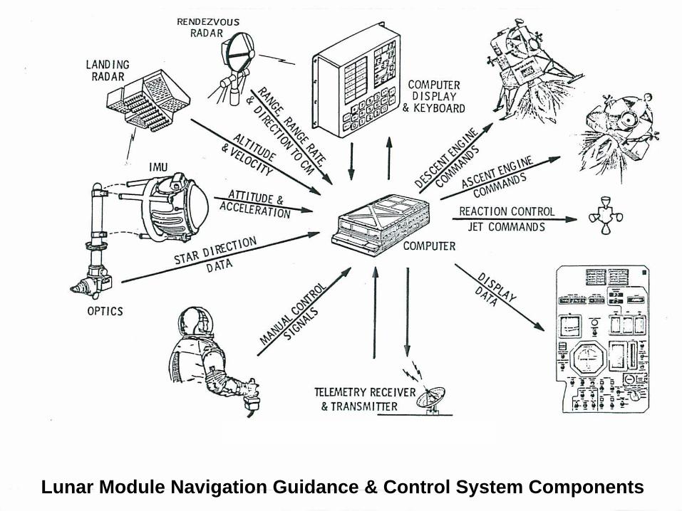
Lunar Module Navigation Guidance & Control System Components
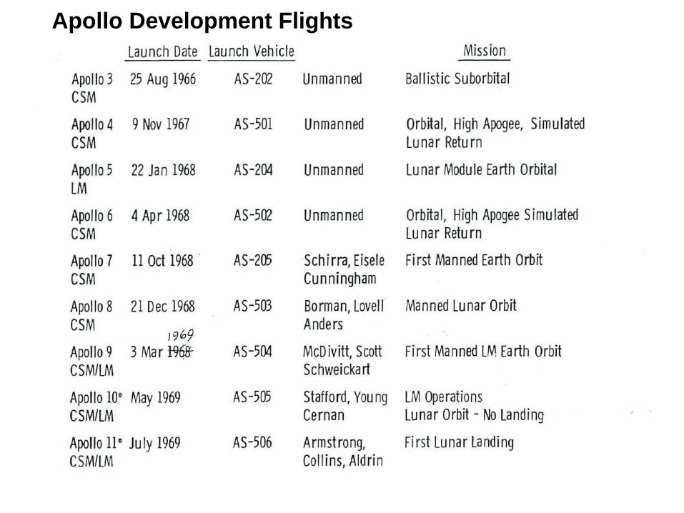
Apollo Development Flights
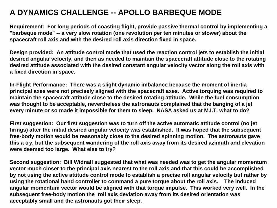
A DYNAMICS CHALLENGE -- APOLLO BARBEQUE MODE
Requirement: For long periods of coasting flight, provide passive thermal control by implementing a "barbeque mode" -- a very slow rotation (one revolution per ten minutes or slower) about the spacecraft roll axis and with the desired roll axis direction fixed in space.
Design provided: An attitude control mode that used the reaction control jets to establish the initial desired angular velocity, and then as needed to maintain the spacecraft attitude close to the rotating desired attitude associated with the desired constant angular velocity vector along the roll axis with a fixed direction in space.
In-Flight Performance: There was a slight dynamic imbalance because the moment of inertia principal axes were not precisely aligned with the spacecraft axes. Active torquing was required to maintain the spacecraft attitude close to the desired rotating attitude. While the fuel consumption was thought to be acceptable, nevertheless the astronauts complained that the banging of a jet every minute or so made it impossible for them to sleep. NASA asked us at M.I.T. what to do?
First suggestion: Our first suggestion was to turn off the active automatic attitude control (no jet firings) after the initial desired angular velocity was established. It was hoped that the subsequent free-body motion would be reasonably close to the desired spinning motion. The astronauts gave this a try, but the subsequent wandering of the roll axis away from its desired azimuth and elevation were deemed too large. What else to try?
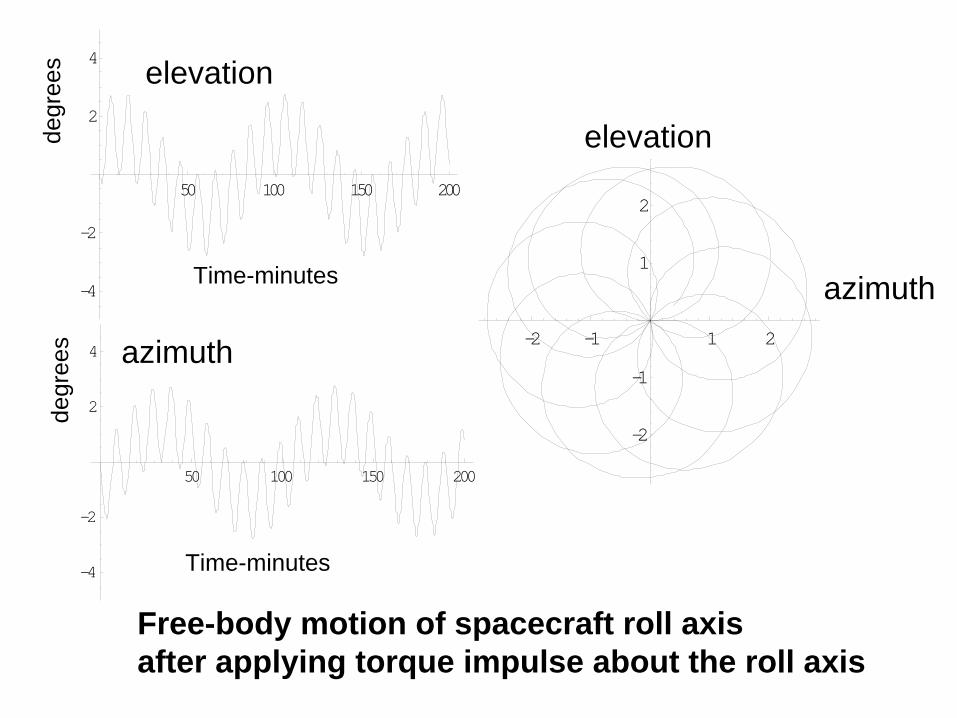
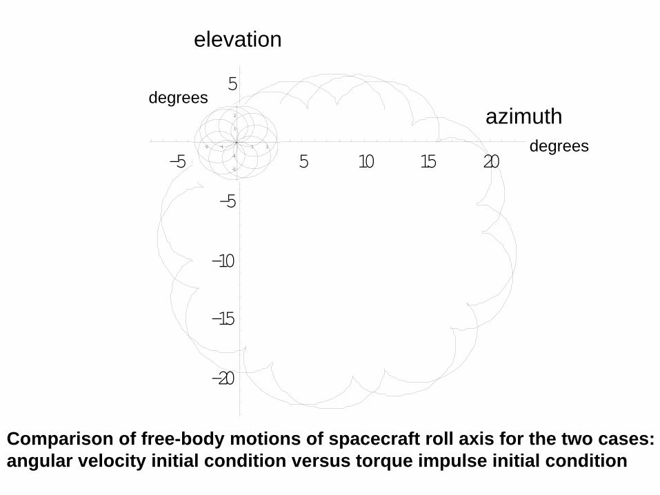
Second suggestion: Bill Widnall suggested that what was needed was to get the angular momentum vector much closer to the principal axis nearest to the roll axis and that this could be accomplished by not using the active attitude control mode to establish a precise roll angular velocity but rather by using the rotational hand controller to command a pure torque about the roll axis. The induced angular momentum vector would be aligned with that torque impulse. This worked very well. In the subsequent free-body motion the roll axis deviation away from its desired orientation was acceptably small and the astronauts got their sleep.
Yaw axis z
Roll axis x
Pitch axis y
G
wx
H H=M
Active torquing required to have spacecraft roll axis remain alignedwith desired angular velocity vector, which is fixed in space
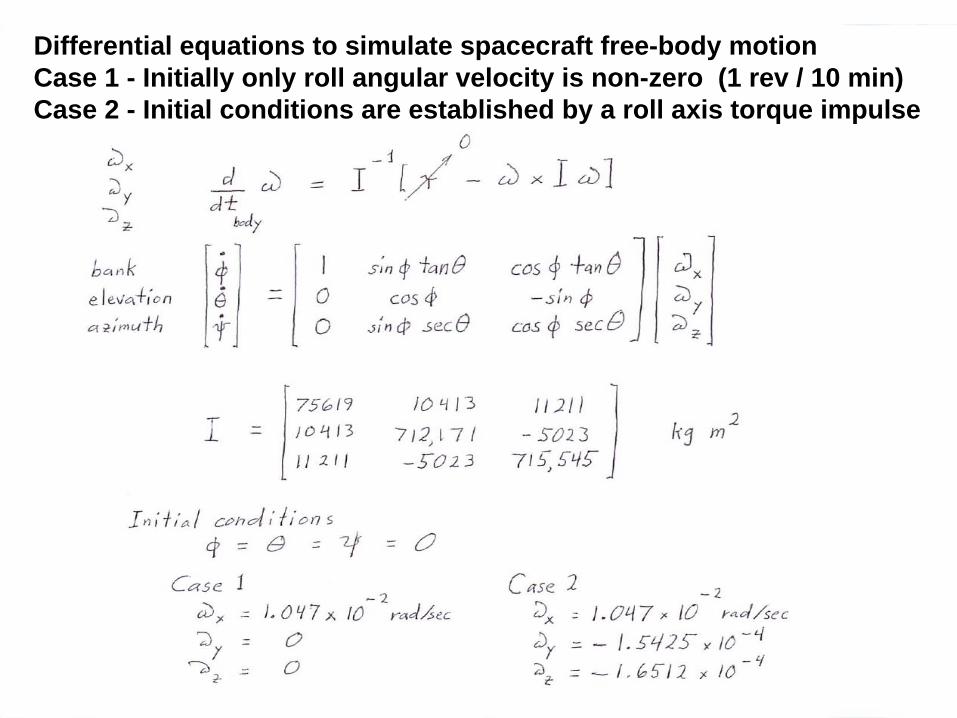
Differential equations to simulate spacecraft free-body motionCase 1 - Initially only roll angular velocity is non-zero (1 rev / 10 min)Case 2 - Initial conditions are established by a roll axis torque impulse
50 100 150 200
-30
-20
-10
10
20
30
-5 5 10 15 20
-20
-15
-10
-5
5
Time-minutes
degrees
degr
ees
degrees
azimuth
elevationelevation
azimuth
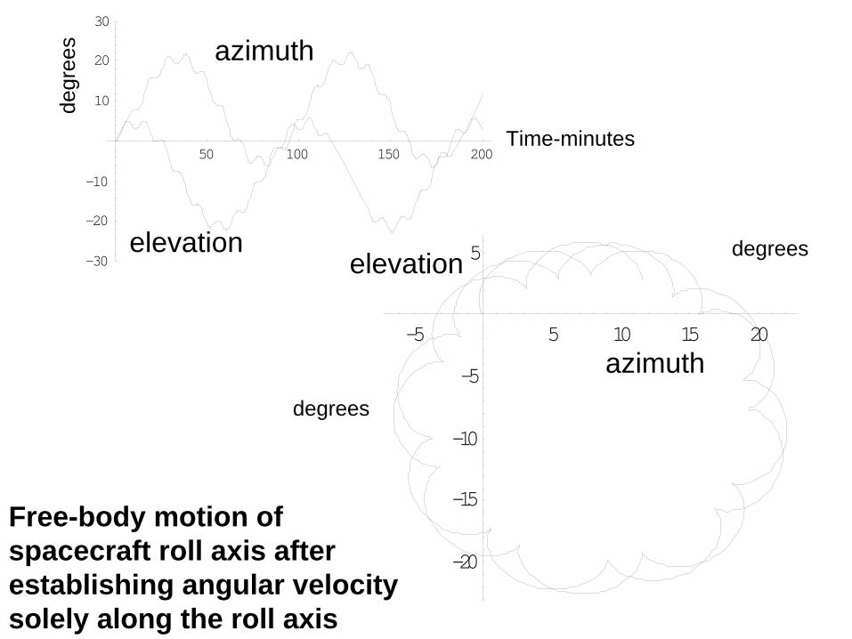
Free-body motion of spacecraft roll axis after establishing angular velocity solely along the roll axis
H fixed in spacew
initial roll axis
principal axis
body cone
space cone
11.4 deg
1.38 deg
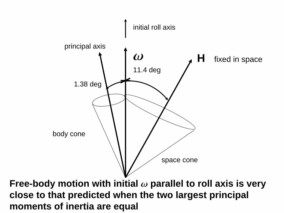
Free-body motion with initial w
parallel to roll axis is very close to that predicted when the two largest principal moments of inertia are equal
H fixed in spacew
initial roll axis and initial torque impulse
principal axis
body cone space cone
1.23 deg1.38 deg
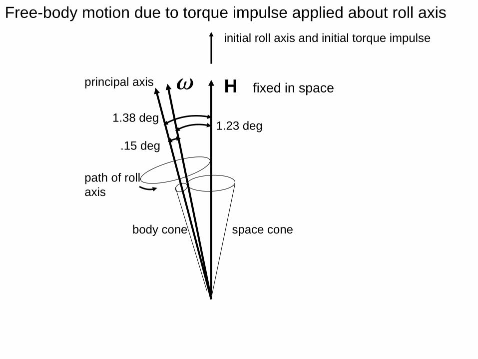
Free-body motion due to torque impulse applied about roll axis
.15 deg
path of roll axis
50 100 150 200
-4
-2
2
4
50 100 150 200
-4
-2
2
4-2 -1 1 2
-2
-1
1
2
azimuth
elevation
elevation
azimuth
Time-minutes
Time-minutes
degr
ees
degr
ees
Free-body motion of spacecraft roll axisafter applying torque impulse about the roll axis
-5 5 10 15 20
-20
-15
-10
-5
5
-2 -1 1 2
-2
-1
1
2 azimuth
elevation
degrees
degrees
Comparison of free-body motions of spacecraft roll axis for the two cases: angular velocity initial condition versus torque impulse initial condition
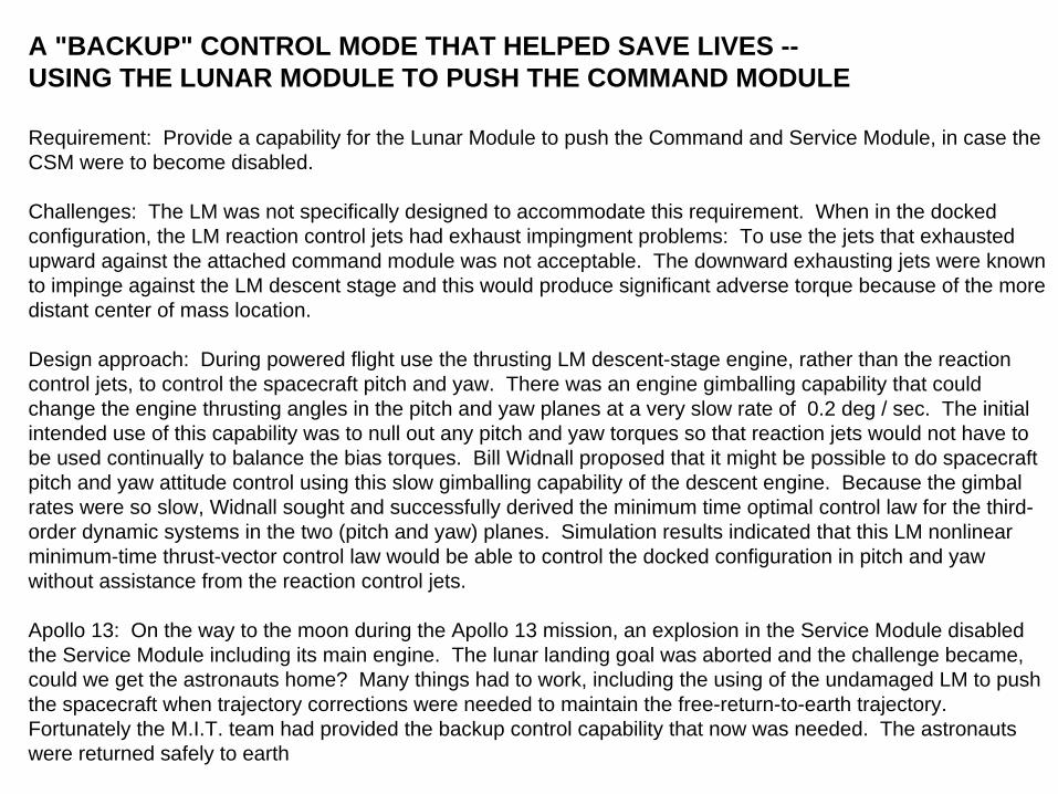
A "BACKUP" CONTROL MODE THAT HELPED SAVE LIVES --USING THE LUNAR MODULE TO PUSH THE COMMAND MODULE
Requirement: Provide a capability for the Lunar Module to push the Command and Service Module, in case the CSM were to become disabled.
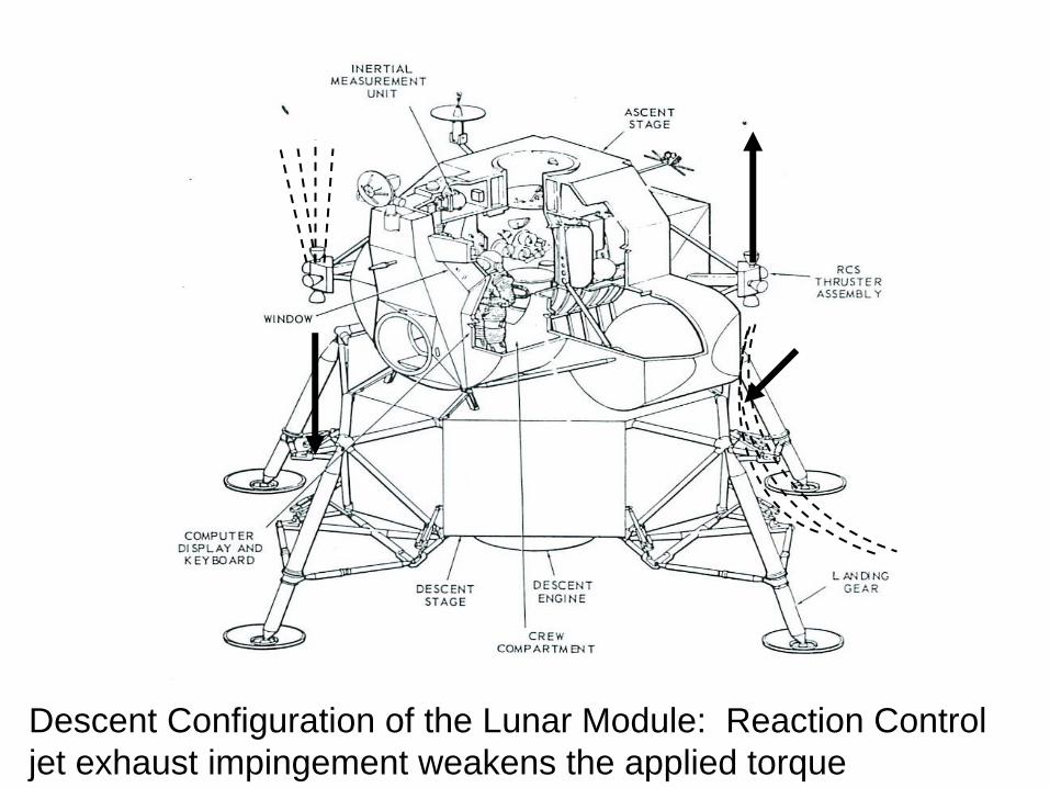
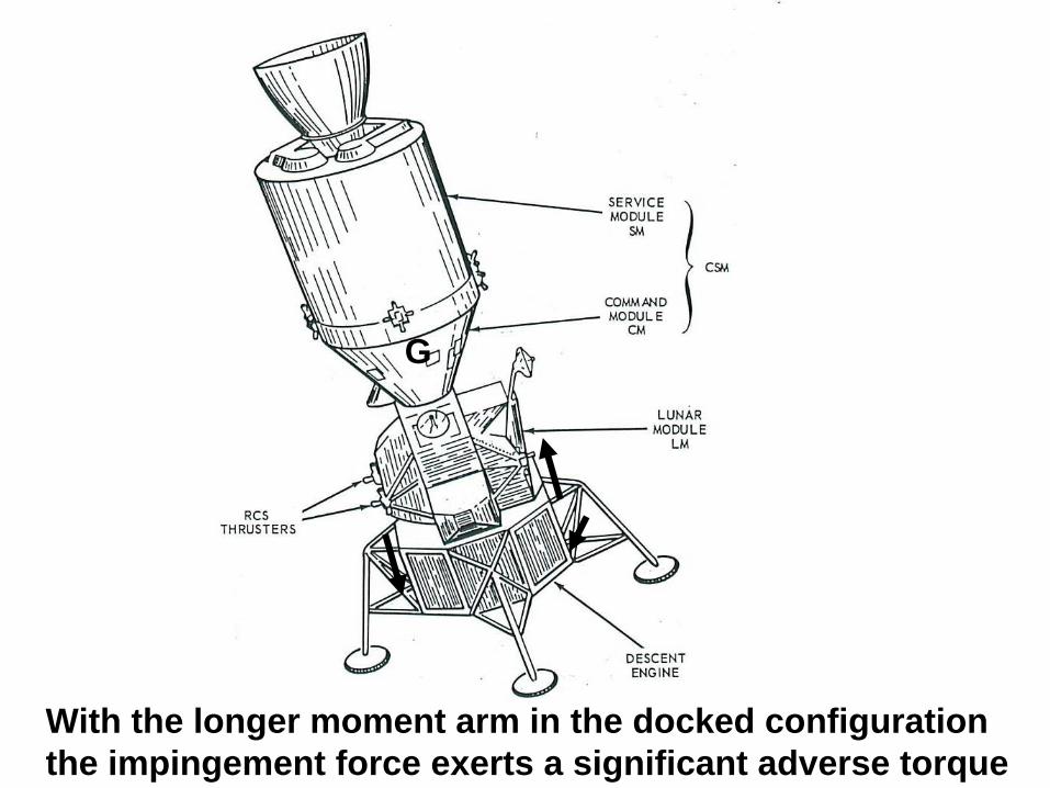
Challenges: The LM was not specifically designed to accommodate this requirement. When in the docked configuration, the LM reaction control jets had exhaust impingment problems: To use the jets that exhausted upward against the attached command module was not acceptable. The downward exhausting jets were known to impinge against the LM descent stage and this would produce significant adverse torque because of the more distant center of mass location.
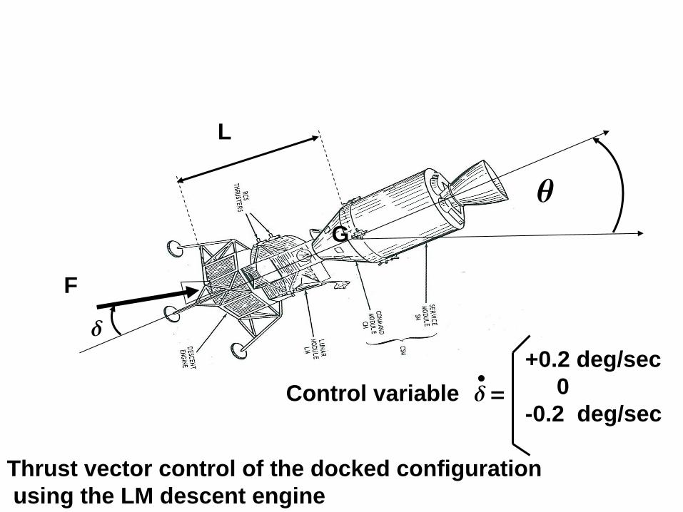
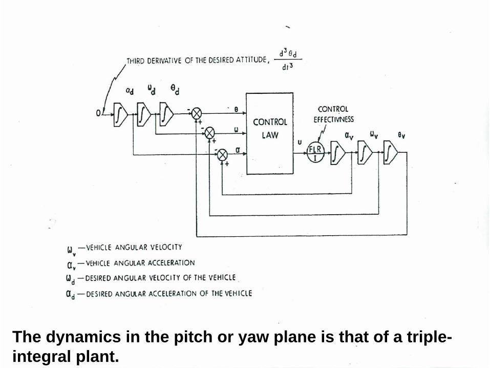
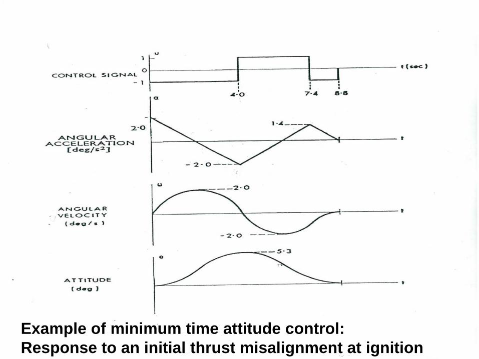
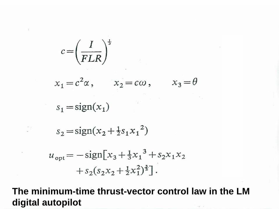
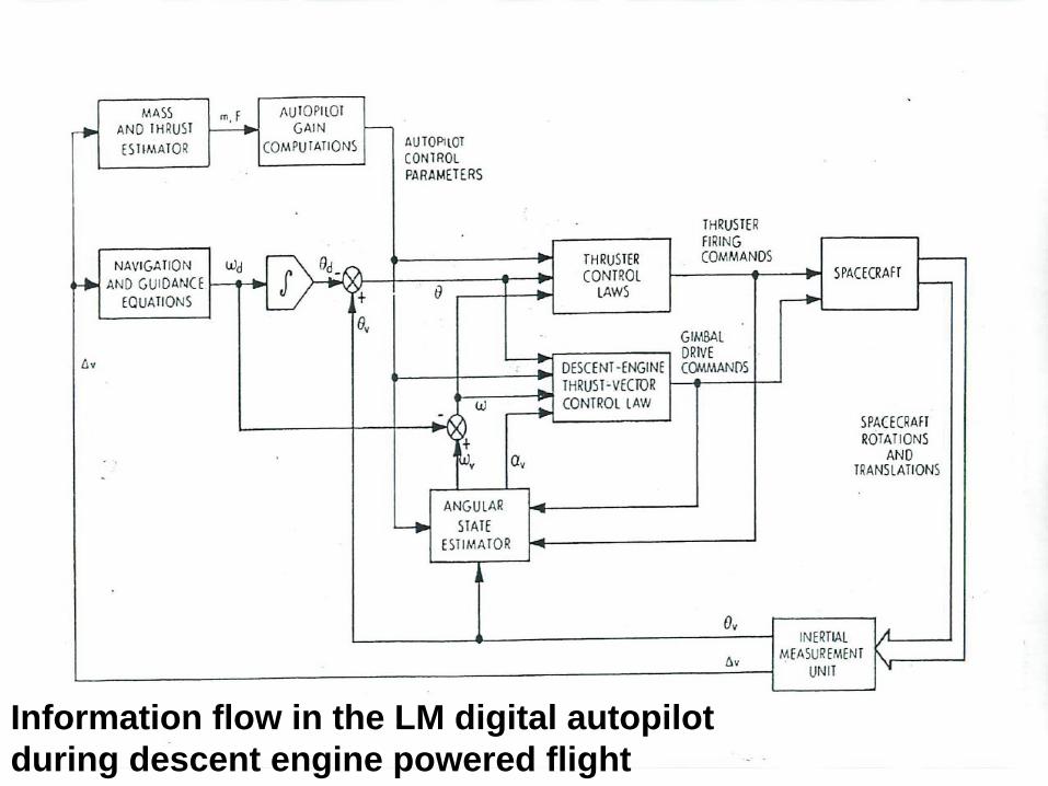
Design approach: During powered flight use the thrusting LM descent-stage engine, rather than the reaction control jets, to control the spacecraft pitch and yaw. There was an engine gimballing capability that could change the engine thrusting angles in the pitch and yaw planes at a very slow rate of 0.2 deg / sec. The initial intended use of this capability was to null out any pitch and yaw torques so that reaction jets would not have to be used continually to balance the bias torques. Bill Widnall proposed that it might be possible to do spacecraft pitch and yaw attitude control using this slow gimballing capability of the descent engine. Because the gimbal rates were so slow, Widnall sought and successfully derived the minimum time optimal control law for the third- order dynamic systems in the two (pitch and yaw) planes. Simulation results indicated that this LM nonlinear minimum-time thrust-vector control law would be able to control the docked configuration in pitch and yaw without assistance from the reaction control jets.
Apollo 13: On the way to the moon during the Apollo 13 mission, an explosion in the Service Module disabled the Service Module including its main engine. The lunar landing goal was aborted and the challenge became, could we get the astronauts home? Many things had to work, including the using of the undamaged LM to push the spacecraft when trajectory corrections were needed to maintain the free-return-to-earth trajectory. Fortunately the M.I.T. team had provided the backup control capability that now was needed. The astronauts were returned safely to earth
Descent Configuration of the Lunar Module: Reaction Control jet exhaust impingement weakens the applied torque
G
With the longer moment arm in the docked configuration the impingement force exerts a significant adverse torque
G
q
d
L
F
Control variable d =
+0.2 deg/sec0
-0.2 deg/sec
Thrust vector control of the docked configurationusing the LM descent engine
The dynamics in the pitch or yaw plane is that of a triple- integral plant.
Example of minimum time attitude control:Response to an initial thrust misalignment at ignition
The minimum-time thrust-vector control law in the LM digital autopilot
Information flow in the LM digital autopilot during descent engine powered flight
MIT OpenCourseWarehttp://ocw.mit.edu
16.07 Dynamics Fall 2009
For information about citing these materials or our Terms of Use, visit: http://ocw.mit.edu/terms.