17
DYNAMITE Portable Load Bank

DYNAMITE
Portable Load Bank
dynaMITE Load Bank Manual
June 8, 2021 • Simplex Service 800-637-8603 • Page 2
This manual was last revised:
June 8, 2021For up-to-date information on this product or others,
please contact Simplex at 800-637-8603 or
visit us on the web at www.simplexdirect.com.
dynaMITE Load Bank Manual
June 8, 2021 • Simplex Service 800-637-8603 • Page 3
Table of Contents
I. Warnings and Cautions .................................................. 4I-A. Safety information symbols ................................................................... 4 I-B. Cautions .......................................................................................... 4
II. Description and Specification ......................................... 7 II-A. Overview of Use................................................................................ 7 II-B. Load Elements .................................................................................. 7 II-C. Control System ................................................................................. 7 II-D. Cooling System ................................................................................. 7
III. Unpacking ................................................................ 9 III-A. Included Components and Parts ............................................................ 9 III-B. Primary Inspection ............................................................................ 9
IV. Installation ............................................................ 10 IV-A. Load Bank Placement ....................................................................... 10 IV-B. Wiring the load bank ........................................................................ 10
V. Operating Instructions ............................................... 12V-A. Conducting a Test ............................................................................ 12 V-B. Metering Line Trends Screen ............................................................... 12 V-C. Single Unit Monitoring ....................................................................... 13 V-D. Shutdown ...................................................................................... 13 V-E. Maintenance Mode ............................................................................ 13 V-F. Diagnostics Screen ............................................................................ 13
VI. Alarms and Warnings ................................................ 14 VI-A. Alarms ......................................................................................... 14 VI-B. Warnings ....................................................................................... 14
VII. Troubleshooting ..................................................... 15 VII-A. General maintenance ...................................................................... 15 VII-B. Each Operation .............................................................................. 15 VII-C. Troubleshooting ............................................................................. 15 VII-D. Intake Temp. Failure ....................................................................... 15 VII-E. Exhausts Temp.Failure ..................................................................... 16 VII-F. Fan Failure ................................................................................... 16 VII-G. Over Voltage ................................................................................. 16
dynaMITE Load Bank Manual
June 8, 2021 • Simplex Service 800-637-8603 • Page 4
I. WARNINGS AND CAUTIONS
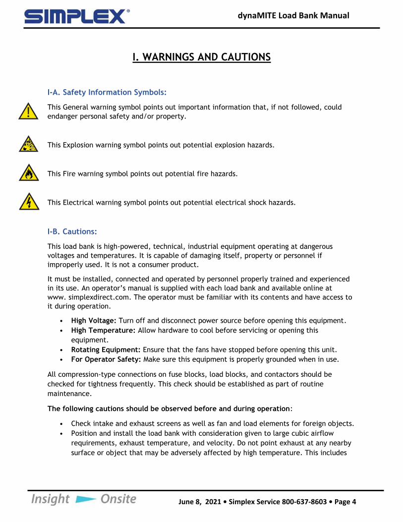
I-A. Safety Information Symbols:
This General warning symbol points out important information that, if not followed, could
endanger personal safety and/or property.
This Explosion warning symbol points out potential explosion hazards.
This Fire warning symbol points out potential fire hazards.
This Electrical warning symbol points out potential electrical shock hazards.
I-B. Cautions:
This load bank is high-powered, technical, industrial equipment operating at dangerous
voltages and temperatures. It is capable of damaging itself, property or personnel if
improperly used. It is not a consumer product.
It must be installed, connected and operated by personnel properly trained and experienced
in its use. An operator’s manual is supplied with each load bank and available online at
www. simplexdirect.com. The operator must be familiar with its contents and have access to
it during operation.
• High Voltage: Turn off and disconnect power source before opening this equipment.
• High Temperature: Allow hardware to cool before servicing or opening this
equipment.
• Rotating Equipment: Ensure that the fans have stopped before opening this unit.
• For Operator Safety: Make sure this equipment is properly grounded when in use.
All compression-type connections on fuse blocks, load blocks, and contactors should be
checked for tightness frequently. This check should be established as part of routine
maintenance.
The following cautions should be observed before and during operation:
• Check intake and exhaust screens as well as fan and load elements for foreign objects.
• Position and install the load bank with consideration given to large cubic airflow
requirements, exhaust temperature, and velocity. Do not point exhaust at any nearby
surface or object that may be adversely affected by high temperature. This includes
dynaMITE Load Bank Manual
June 8, 2021 • Simplex Service 800-637-8603 • Page 5
but is not limited to painted surfaces, tar paper and asphalt roofs, water sprinkler
heads, fire alarms, and volatile material.
• Do not use in confined spaces. The load bank may have to compete with cooling air
requirements of a nearby running engine generator set where cooling air intake to a
confined space may not be adequate for both engine and load bank. Be especially
careful not to bounce hot exhaust air off nearby obstructions for re-circulation through
the load bank.
• Verify that all control switch positions are set correctly for your intended usage before
connecting the load bank to the source to be tested.
• The load cables carry high amperage. Be constantly aware of possibility of inductively
heating adjacent ferrous objects to temperatures sufficient to damage cable
insulation.
• Always connect the safety ground cable to a proper ground. Do not rely on a possible
grounded neutral somewhere else in the system.
• Do not let the load bank run unattended for long periods of time.
• Do not store or operate in rain unless adequate protection is provided.
• Routinely inspect all components and electrical connections for tightness and
integrity.
• Repair any damaged or degraded components and wiring without delay.
• If technical assistance, service, or parts are needed, please call 800-837-8603
(24 Hours).
• All hardware covered by this manual have dangerous electrical voltages and can cause
fatal electrical shock. Avoid contact with bare wires, terminals, connections, etc.
Ensure all appropriate covers, guards, grounds, and barriers are in place before
operating the equipment. If work must be done around an operating unit, stand on an
insulated dry surface to reduce the risk of electrocution.
• Do not handle any kind of electrical device while standing in water, while barefoot, or
while your hands or feet are wet.
• If people must stand on metal or concrete while installing, servicing, adjusting, or
repairing this equipment, place insulative mats over a dry wooden platform. Work on
the equipment only while standing on such insulative mats.
• The National Electrical Code (NEC), Article 250 requires the frame to be connected to
an approved earth ground and/or grounding rods. This grounding will help prevent
dangerous electrical shock that might be caused by a ground fault condition or by
static electricity. Never disconnect the ground wire while the load bank is in use.
• Wire gauge sizes of electrical wiring, cables, and cord sets must be adequate to
handle the maximum electrical current (ampacity) to which they will be subjected.
• Before installing or servicing this (and related) equipment, ensure that all power
voltage supplies are completely turned off at their source. Failure to do so can result
in hazardous and possibly fatal electrical shock.
• In case of accident caused by electric shock, immediately shut down the source of
electrical power. If this is not possible, attempt to free the victim from the live
conductor. AVOID DIRECT CONTACT WITH THE VICTIM. Use a nonconducting
dynaMITE Load Bank Manual
June 8, 2021 • Simplex Service 800-637-8603 • Page 6
implement, such as a dry rope or board, to free the victim from the live conductor. If
the victim is unconscious, apply first aid and seek immediate medical attention.
• Never wear jewelry when working on this equipment. Jewelry can conduct electricity
resulting in electric shock or may get caught in moving components causing injury.
• Keep a fire extinguisher near the hardware at all times. Do NOT use any carbon tetra-
chloride type extinguisher. Its fumes are toxic, and the liquid can deteriorate wiring
insulation. Keep the extinguisher properly charged and be familiar with its use. If
there are any questions pertaining to fire extinguishers, please consult the local fire
department.
• The illustrations in this manual are examples only and may differ from your load bank.
• Load Bank warranty is void if incorrectly cooled.
dynaMITE Load Bank Manual
June 8, 2021 • Simplex Service 800-637-8603 • Page 7
II. DESCRIPTION AND SPECIFICATION
II-A. Overview of Use
The Simplex dynaMITE is a large-capacity, high-performance portable load bank
designed to test AC generators and UPS systems.
The dynaMITE portable load bank is a self-contained testing system. In addition to test
instrumentation, the load bank includes connection cables, high-capacity cooling
system, rugged load elements, complete load-application control devices, and
automatic system protection devices. Lifting eyes, forklift channels, and moving handles
make transporting the unit easier. The cable compartment allows for convenient storage
of the connection cables behind a hinged door on the rear of the unit. A hinged cover
protects the 8-inch touchscreen control panel.
II-B. Load Elements
The dynaMITE load bank utilizes specially designed “Powr-Web” resistive elements. High
temperature, ceramic clad, stainless steel rods rigidly support the elements. Discrete
trays, assembled in a vertical “stack,” house the elements. Each tray is independently
serviceable without disturbing adjacent trays.
II-C. Control System
The load bank is controlled by a programmable logic controller with a touchscreen
interface. Multiple units may be connected to increase system capacity.
Fan and control power is supplied either through the testing source or an external
supply.
The control system automatically connects control contactors for applied voltage,
detects control power source and volt- age, and detects cooling fan motor and motor
connection.
II-D. Cooling System
The load elements are cooled by a forced air system. This system consists of a directly-
driven, shrouded aluminum fan blade. Air flows vertically through the load bank, from
bottom to top, through screened intake and exhaust vents.
dynaMITE Load Bank Manual
June 8, 2021 • Simplex Service 800-637-8603 • Page 8
Table 1: Specifications
Voltage 240/480V, 3-ph
Capacity 400KW
Size 34”W x 48” H x 60” D
Frequency 50, 60Hz
Temp 120 F
Fan/ControlPower Internal: 208-240/416-480V, 3-phase, 60Hz; 220/380-
416V,3-phase, 50Hz
External: 208-230/460V, 3-phase, 60Hz; 220/380-416V, 3-
phase, 50Hz
Weight 1,000lbs.
Airflow 10,500 CFM
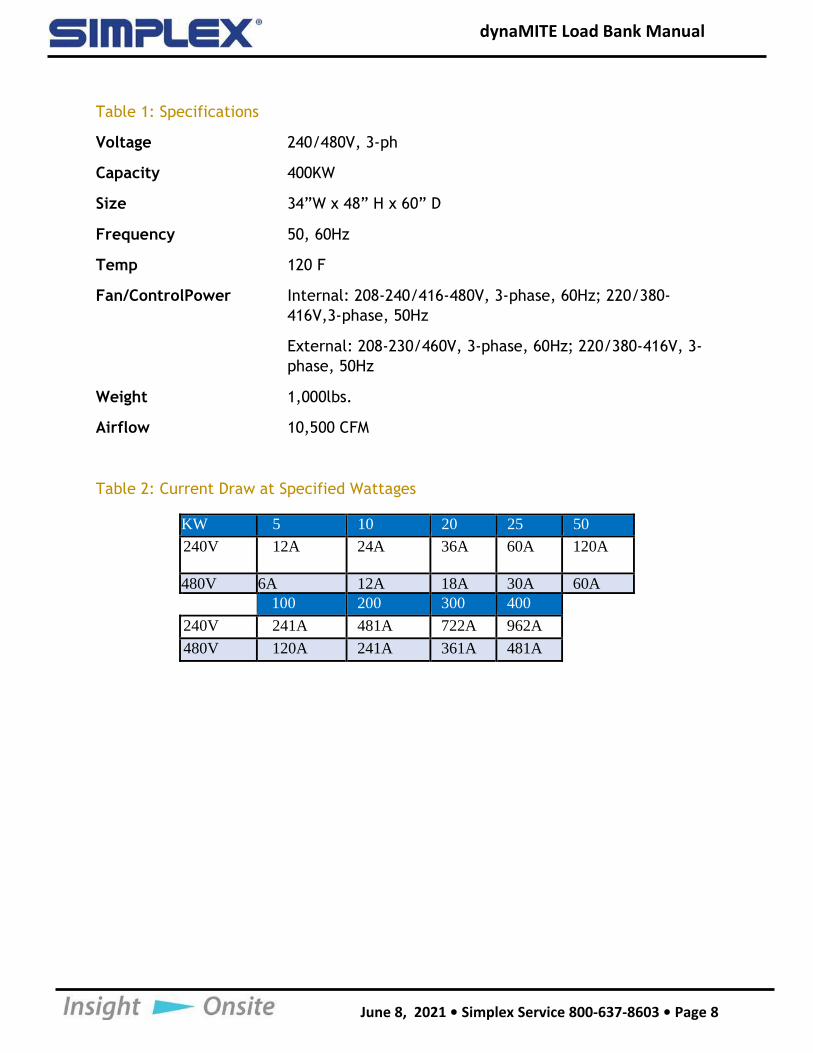
Table 2: Current Draw at Specified Wattages
KW 5 10 20 25 50
240V 12A 24A 36A 60A 120A
480V 6A 12A 18A 30A 60A
100 200 300 400
240V 241A 481A 722A 962A
480V 120A 241A 361A 481A
dynaMITE Load Bank Manual
June 8, 2021 • Simplex Service 800-637-8603 • Page 9
Call Simplex if you have any problems during installation.
24-hour contact at 800-637-8603
III. UNPACKING
III-A. Included Components and Parts
The following items are included with your load bank. If any of the following are not
included, please contact your Simplex representative or call Simplex Direct, Inc., at 800-
637-8603.
1. Load bank
2. Manual
3. Electrical drawings package
III-B. Primary Inspection
Preventative visual inspection of the shipping crate and the load bank is advised.
Physical or electrical problems due to handling and vibration may occur. Never apply
power to a load bank before performing this procedure. The following five-point
inspection is recommended before installation and as part of a 6-month maintenance
schedule or as a load bank is relocated:
1. If the crate shows any signs of damage, examine the load bank in the corresponding
areas for signs of initial problems.
2. Check the entire outside of the cabinet for any visual damage, which could cause
internal electrical or mechanical problems due to reduced clearance.
3. Inspect all relays and control modules. Make sure all components are secure in their
bases and safety bails are in place. Spot check electrical connections for tightness.
If any loose connections are found, inspect and tighten all remaining connections.
4. Examine all accessible internal electrical components such as fuses, contactors, and
relays. Check lugged wires at these components.
5. Visually inspect the element chamber for foreign objects, broken ceramic
insulators, and mechanical damage.
dynaMITE Load Bank Manual
June 8, 2021 • Simplex Service 800-637-8603 • Page 10
IV. INSTALLATION
IV-A. Load Bank Placement
Proper placement of the load bank is essential for the operators’ safety and maintaining the
integrity of the load bank.
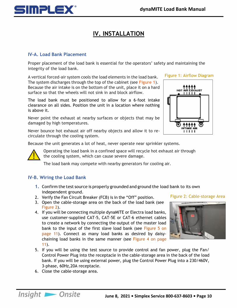
A vertical forced-air system cools the load elements in the load bank.
The system discharges through the top of the cabinet (see Figure 1).
Because the air intake is on the bottom of the unit, place it on a hard
surface so that the wheels will not sink in and block airflow.
The load bank must be positioned to allow for a 6-foot intake
clearance on all sides. Position the unit in a location where nothing
is above it.
Never point the exhaust at nearby surfaces or objects that may be
damaged by high temperatures.
Never bounce hot exhaust air off nearby objects and allow it to re-
circulate through the cooling system.
Because the unit generates a lot of heat, never operate near sprinkler systems.
Operating the load bank in a confined space will recycle hot exhaust air through
the cooling system, which can cause severe damage.
The load bank may compete with nearby generators for cooling air.
IV-B. Wiring the Load Bank
1. Confirm the test source is properly grounded and ground the load bank to its own
independent ground.
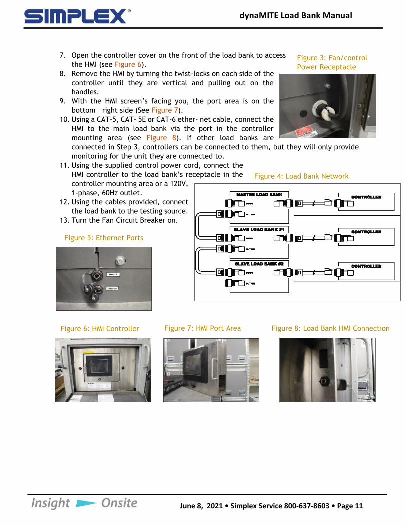
2. Verify the Fan Circuit Breaker (FCB) is in the “Off” position.3. Open the cable-storage area on the back of the load bank (see
Figure 2).4. If you will be connecting multiple dynaMITE or Electra load banks,
use customer-supplied CAT-5, CAT-5E or CAT-6 ethernet cables
to create a network by connecting the output of the master load
bank to the input of the first slave load bank (see Figure 5 on
page 11). Connect as many load banks as desired by daisy-
chaining load banks in the same manner (see Figure 4 on page
11).
5. If you will be using the test source to provide control and fan power, plug the Fan/
Control Power Plug into the receptacle in the cable-storage area in the back of the load
bank. If you will be using external power, plug the Control Power Plug into a 230/460V,
3-phase, 60Hz,20A receptacle.
6. Close the cable-storage area.
Figure 1: Airflow Diagram
Figure 2: Cable-storage Area
dynaMITE Load Bank Manual
June 8, 2021 • Simplex Service 800-637-8603 • Page 11
7. Open the controller cover on the front of the load bank to access
the HMI (see Figure 6).
8. Remove the HMI by turning the twist-locks on each side of the
controller until they are vertical and pulling out on the
handles.
9. With the HMI screen’s facing you, the port area is on the
bottom right side (See Figure 7).
10. Using a CAT-5, CAT- 5E or CAT-6 ether- net cable, connect the
HMI to the main load bank via the port in the controller
mounting area (see Figure 8). If other load banks are
connected in Step 3, controllers can be connected to them, but they will only provide
monitoring for the unit they are connected to.
11. Using the supplied control power cord, connect the
HMI controller to the load bank’s receptacle in the
controller mounting area or a 120V,
1-phase, 60Hz outlet.
12. Using the cables provided, connect
the load bank to the testing source.
13. Turn the Fan Circuit Breaker on.
Figure 3: Fan/control
Power Receptacle
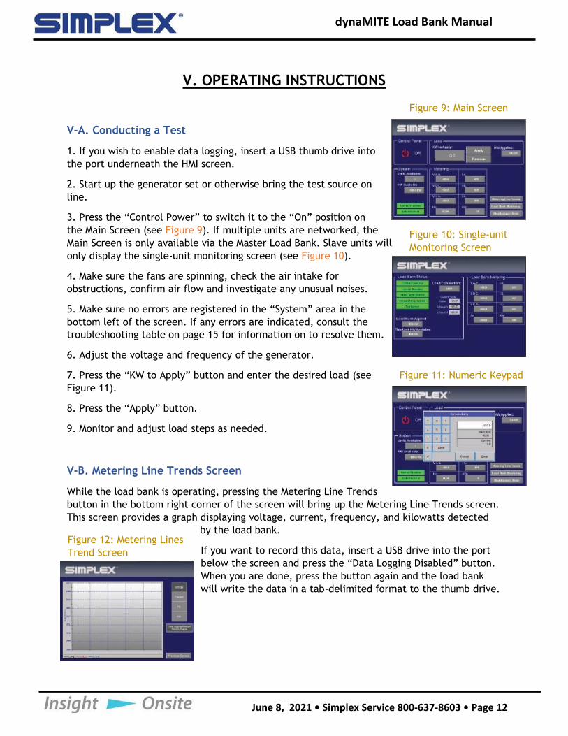
Figure 4: Load Bank Network
Figure 5: Ethernet Ports
Figure 6: HMI Controller Figure 7: HMI Port Area Figure 8: Load Bank HMI Connection
dynaMITE Load Bank Manual
June 8, 2021 • Simplex Service 800-637-8603 • Page 12
V. OPERATING INSTRUCTIONS
V-A. Conducting a Test
1. If you wish to enable data logging, insert a USB thumb drive into
the port underneath the HMI screen.
2. Start up the generator set or otherwise bring the test source on
line.
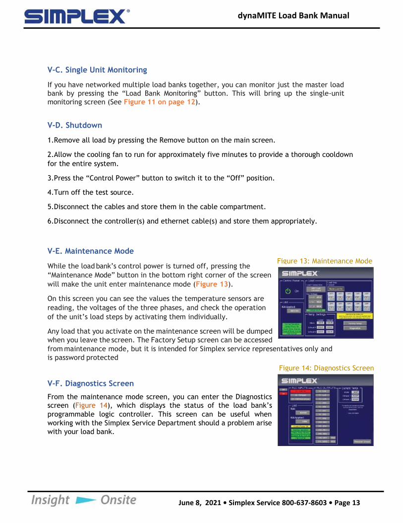
3. Press the “Control Power” to switch it to the “On” position on
the Main Screen (see Figure 9). If multiple units are networked, the
Main Screen is only available via the Master Load Bank. Slave units will
only display the single-unit monitoring screen (see Figure 10).
4. Make sure the fans are spinning, check the air intake for
obstructions, confirm air flow and investigate any unusual noises.
5. Make sure no errors are registered in the “System” area in the
bottom left of the screen. If any errors are indicated, consult the
troubleshooting table on page 15 for information on to resolve them.
6. Adjust the voltage and frequency of the generator.
7. Press the “KW to Apply” button and enter the desired load (see
Figure 11).
8. Press the “Apply” button.
9. Monitor and adjust load steps as needed.
V-B. Metering Line Trends Screen
While the load bank is operating, pressing the Metering Line Trends
button in the bottom right corner of the screen will bring up the Metering Line Trends screen.
This screen provides a graph displaying voltage, current, frequency, and kilowatts detected
by the load bank.
If you want to record this data, insert a USB drive into the port
below the screen and press the “Data Logging Disabled” button.
When you are done, press the button again and the load bank
will write the data in a tab-delimited format to the thumb drive.
Figure 9: Main Screen
Figure 10: Single-unit
Monitoring Screen
Figure 11: Numeric Keypad
Figure 12: Metering Lines
Trend Screen
dynaMITE Load Bank Manual
June 8, 2021 • Simplex Service 800-637-8603 • Page 13
V-C. Single Unit Monitoring
If you have networked multiple load banks together, you can monitor just the master load
bank by pressing the “Load Bank Monitoring” button. This will bring up the single-unit
monitoring screen (See Figure 11 on page 12).
V-D. Shutdown
1.Remove all load by pressing the Remove button on the main screen.
2.Allow the cooling fan to run for approximately five minutes to provide a thorough cooldown
for the entire system.
3.Press the “Control Power” button to switch it to the “Off” position.
4.Turn off the test source.
5.Disconnect the cables and store them in the cable compartment.
6.Disconnect the controller(s) and ethernet cable(s) and store them appropriately.
V-E. Maintenance Mode
While the load bank’s control power is turned off, pressing the
“Maintenance Mode” button in the bottom right corner of the screen
will make the unit enter maintenance mode (Figure 13).
On this screen you can see the values the temperature sensors are
reading, the voltages of the three phases, and check the operation
of the unit’s load steps by activating them individually.
Any load that you activate on the maintenance screen will be dumped
when you leave the screen. The Factory Setup screen can be accessed
from maintenance mode, but it is intended for Simplex service representatives only and
is password protected
V-F. Diagnostics Screen
From the maintenance mode screen, you can enter the Diagnostics
screen (Figure 14), which displays the status of the load bank’s
programmable logic controller. This screen can be useful when
working with the Simplex Service Department should a problem arise
with your load bank.
Figure 13: Maintenance Mode
Figure 14: Diagnostics Screen
dynaMITE Load Bank Manual
June 8, 2021 • Simplex Service 800-637-8603 • Page 14
VI. ALARMS AND WARNINGS
DynaMITE load banks are protected by four types of sensors.
1. Intake temperature, which checks the
incoming air to ensure the load elements can be
adequately cooled.
2. Exhaust temperature, which checks the
temperature of the air coming out the load bank
to ensure the load elements are being adequately cooled.
3. Fan pressure, when ensures the fan blades are forcing air into the load element
chamber.
4. Fan current, which ensures the fan motor isn’t overloaded or jammed.
VI-A. Alarms
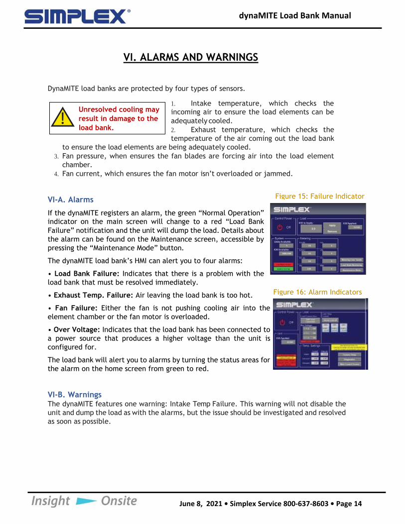
If the dynaMITE registers an alarm, the green “Normal Operation”
indicator on the main screen will change to a red “Load Bank
Failure” notification and the unit will dump the load. Details about
the alarm can be found on the Maintenance screen, accessible by
pressing the “Maintenance Mode” button.
The dynaMITE load bank’s HMI can alert you to four alarms:
• Load Bank Failure: Indicates that there is a problem with the
load bank that must be resolved immediately.
• Exhaust Temp. Failure: Air leaving the load bank is too hot.
• Fan Failure: Either the fan is not pushing cooling air into the
element chamber or the fan motor is overloaded.
• Over Voltage: Indicates that the load bank has been connected to
a power source that produces a higher voltage than the unit is
configured for.
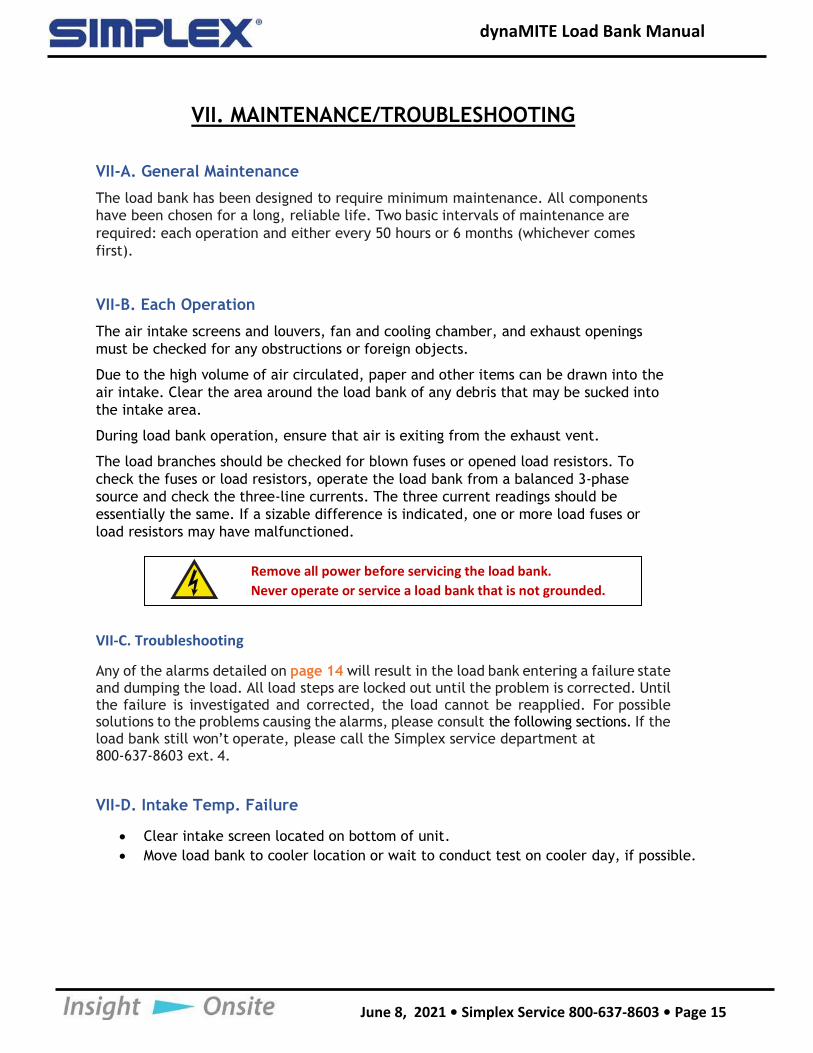
The load bank will alert you to alarms by turning the status areas for
the alarm on the home screen from green to red.
VI-B. WarningsThe dynaMITE features one warning: Intake Temp Failure. This warning will not disable the
unit and dump the load as with the alarms, but the issue should be investigated and resolved
as soon as possible.
Unresolved cooling may
result in damage to the
load bank.
Figure 15: Failure Indicator
Figure 16: Alarm Indicators
dynaMITE Load Bank Manual
June 8, 2021 • Simplex Service 800-637-8603 • Page 15
VII. MAINTENANCE/TROUBLESHOOTING
VII-A. General Maintenance
The load bank has been designed to require minimum maintenance. All components
have been chosen for a long, reliable life. Two basic intervals of maintenance are
required: each operation and either every 50 hours or 6 months (whichever comes
first).
VII-B. Each Operation
The air intake screens and louvers, fan and cooling chamber, and exhaust openings
must be checked for any obstructions or foreign objects.
Due to the high volume of air circulated, paper and other items can be drawn into the
air intake. Clear the area around the load bank of any debris that may be sucked into
the intake area.
During load bank operation, ensure that air is exiting from the exhaust vent.
The load branches should be checked for blown fuses or opened load resistors. To
check the fuses or load resistors, operate the load bank from a balanced 3-phase
source and check the three-line currents. The three current readings should be
essentially the same. If a sizable difference is indicated, one or more load fuses or
load resistors may have malfunctioned.
VII-C. Troubleshooting
Any of the alarms detailed on page 14 will result in the load bank entering a failure state and dumping the load. All load steps are locked out until the problem is corrected. Until the failure is investigated and corrected, the load cannot be reapplied. For possible solutions to the problems causing the alarms, please consult the following sections. If the load bank still won’t operate, please call the Simplex service department at 800-637-8603 ext. 4.
VII-D. Intake Temp. Failure
• Clear intake screen located on bottom of unit.
• Move load bank to cooler location or wait to conduct test on cooler day, if possible.
Remove all power before servicing the load bank.
Never operate or service a load bank that is not grounded.
dynaMITE Load Bank Manual
June 8, 2021 • Simplex Service 800-637-8603 • Page 16
VII-E. Exhausts Temp. Failure
• The unit needs to be serviced. Please call the Simplex service department at
800-637-8603 ext. 4.
• Move the unit to an area that allows for proper air circulation. See “Load Bank
Placement” on page 10 for more information.
VII-F. Fan Failure
• Clear intake screen located on bottom of unit.
• Make sure nothing has jammed the fan blades.
VII-G. Over Voltage
• Connect load bank to appropriate voltage source.

Contact Simplex for all your Load Bank and Fuel Supply needs.
Simplex, Inc. 5300 Rising Moon Road
Springfield, IL 62711
800-637-8603www.simplexdirect.com
This manual and all of its contents Copyright © 2021 Simplex, Inc.
All Rights Reserved.


