1 DZ47-63 SERIES MINIATURE CIRCUIT BREAKER Application The breaker is suitable to serve in the power distribution system for lighting (Corresponding to model B, C) and motor (Corresponding to model D). It mainly functions as overload and short-circuit protection in the line of single- pole of 240V and two-, three-, four-pole of 415V with rated frequency of 50HZ or 60HZ, also for unfrequent making and breaking electrical apparatus and lighting circuit under normal conditional. Model meaning and classification According to number of poles: Classification 1-Pole 2-Pole 3-Pole 4-Pole Model meaning D Z 47 - 63 Casing class rated current DZ: Plastic casing breaker 47: Design sequence No. B D C According to rated current of breaker: 1A, 2A, 3A, 4A, 5A, 6A, 10A, 15A, 16A, 20A, 25A, 32A, 40A, 50A, 63A According to type of instantaneous release:
Transcript
1
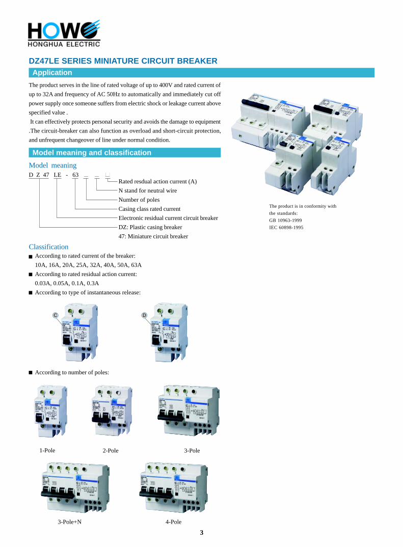
DZ47-63 SERIES MINIATURE CIRCUIT BREAKER
Application
The breaker is suitable to serve in the power distribution system for lighting
(Corresponding to model B, C) and motor (Corresponding to model D). It
mainly functions as overload and short-circuit protection in the line of single-
pole of 240V and two-, three-, four-pole of 415V with rated frequency of 50HZ
or 60HZ, also for unfrequent making and breaking electrical apparatus and
When poles are connected to each other, the peak value of the impulse withstand-voltage between
each poles and the neutral pole is 6000V
When each pole is connected to the neutral pole, the peak value of the impulse withstand-voltage
between poles and the metal support is 8000V
NOTE: The product can withstand peak impulse current of 200A and peak surge over-voltage 2.5Un,and under such a situation
the protection switch can act correctly without mis-operation.
Residual current breaking time
In (A)
25,40,63
I n(A)
0.03,0.05,0.1,0.3
I n
0.1
2I n
0.05
5I n
0.04
I n
0.04 Max. breaking time (s)
Residual current (in) is equal to the breaking time (s) at the following corresponding value
NOTE: I t is the larger one between 500A and the upper limit of instantaneous release range of model B, C, D. When In
0.03A,replacing 5 I n with 0.25A is available.
5
DZ47LE SERIES RESIDUAL CURRENT CIRCUIT BREAKER
Performance curve of release
Type C Type D
Main technical parameter
Item No. Release type RemarkRated current
of release
Test
current
Expected
result
Expected
result
1 C,D -1.13In t 1h Non-release
2 C,D
Current smoothly rises
to specified value
within 5s
1.45In t < 1h Release
Initial status
Cold position
Carried out immediately
after previous test
10~63
10~63
3
C,D -2.55In 1s < t < 60s ReleaseCold positionIn 32
C,D
4
5
C
D
C
D
In > 32
10~63
10~63
10~63
10~63
Cold position
Cold position
Cold position
Cold position
Cold position
2.55In
5In
10In
10In
14In
1s < t < 120s
t 0.1s
t 0.1s
t < 0.1s
t < 0.1s
Release
Non-Release
Non-Release
Release
Release
-
-
-
-
-
6
Application
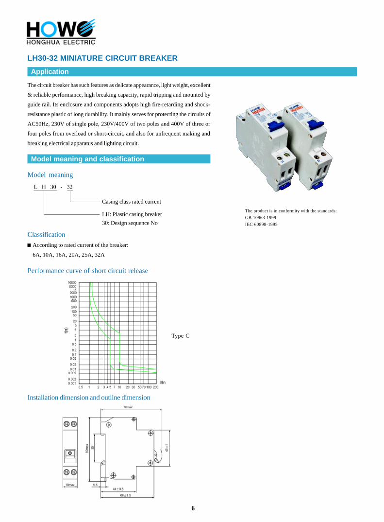
LH30-32 MINIATURE CIRCUIT BREAKER
The circuit breaker has such features as delicate appearance, light weight, excellent
& reliable performance, high breaking capacity, rapid tripping and mounted by
guide rail. Its enclosure and components adopts high fire-retarding and shock-
resistance plastic of long durability. It mainly serves for protecting the circuits of
AC50Hz, 230V of single pole, 230V/400V of two poles and 400V of three or
four poles from overload or short-circuit, and also for unfrequent making and
breaking electrical apparatus and lighting circuit.
The product is in conformity with the standards:
GB 10963-1999
IEC 60898-1995
Type C
Installation dimension and outline dimension
Model meaning and classification
Model meaning
Performance curve of short circuit release
Classification
According to rated current of the breaker:
6A, 10A, 16A, 20A, 25A, 32A
L H 30 - 32
LH: Plastic casing breaker
30: Design sequence No
Casing class rated current
7
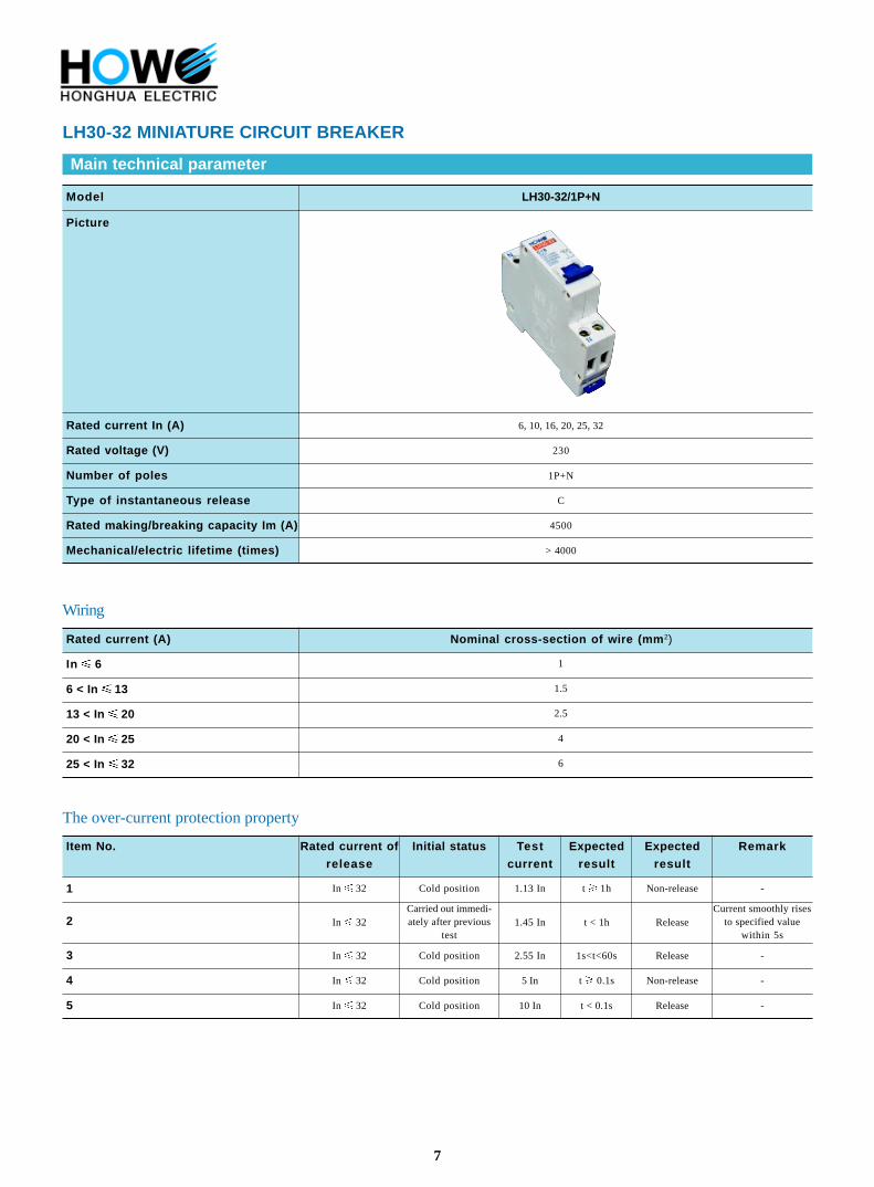
LH30-32 MINIATURE CIRCUIT BREAKER
Main technical parameter
Model LH30-32/1P+N
Picture
6, 10, 16, 20, 25, 32
230
1P+N
C
4500
> 4000
Rated current In (A)
Rated voltage (V)
Number of poles
Type of instantaneous release
Rated making/breaking capacity Im (A)
Mechanical/electric lifetime (times)
Wiring
Rated current (A) Nominal cross-section of wire (mm 2)
In 6
6 < In 13
13 < In 20
20 < In 25
25 < In 32
1
1.5
2.5
4
6
The over-current protection property
Item No.
1
2
3
4
5
Rated current of
release
In 32
In 32
In 32
In 32
In 32
Initial status
Cold position
Carried out immedi-ately after previous
test
Cold position
Cold position
Cold position
Test
current
1.13 In
1.45 In
2.55 In
5 In
10 In
Expected
result
t 1h
t < 1h
1s<t<60s
t 0.1s
t < 0.1s
Expected
result
Non-release
Release
Release
Non-release
Release
Remark
-
Current smoothly risesto specified value
within 5s
-
-
-
8
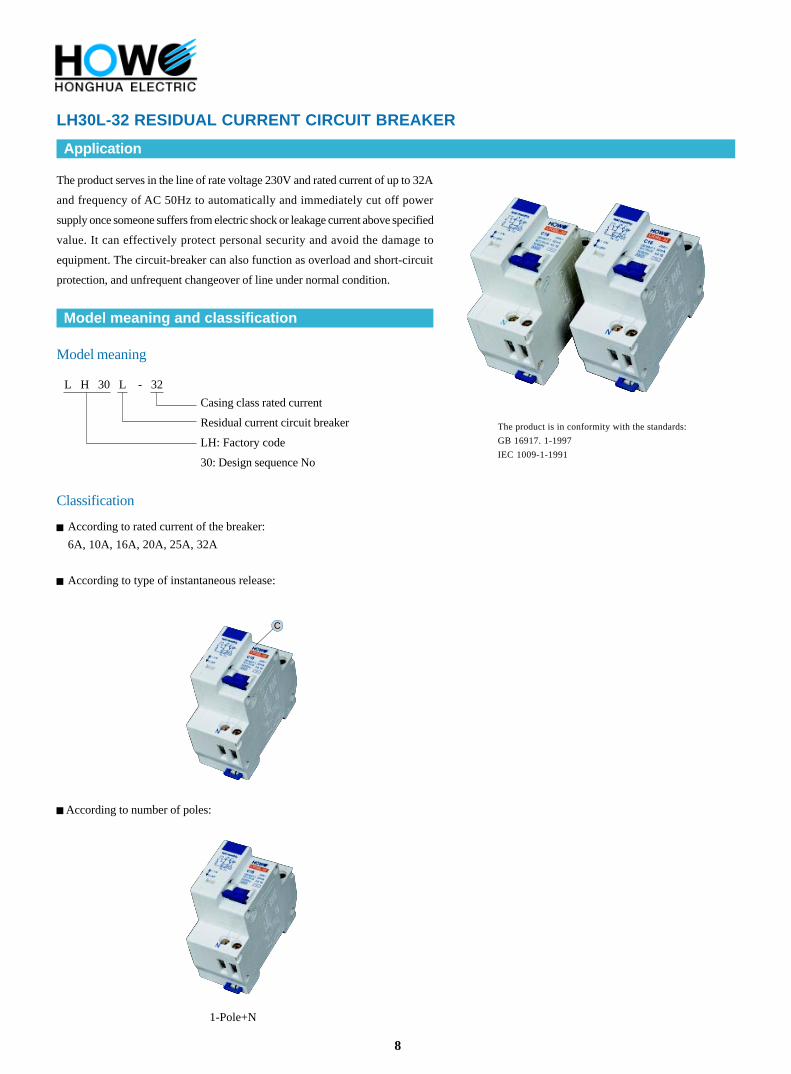
LH30L-32 RESIDUAL CURRENT CIRCUIT BREAKER
Application
The product serves in the line of rate voltage 230V and rated current of up to 32A
and frequency of AC 50Hz to automatically and immediately cut off power
supply once someone suffers from electric shock or leakage current above specified
value. It can effectively protect personal security and avoid the damage to
equipment. The circuit-breaker can also function as overload and short-circuit
protection, and unfrequent changeover of line under normal condition.
The product is in conformity with the standards:
GB 16917. 1-1997
IEC 1009-1-1991
Model meaning
Model meaning and classification
L H 30 L - 32
Casing class rated current
Residual current circuit breaker
LH: Factory code
30: Design sequence No
According to number of poles:
1-Pole+N
Classification
According to rated current of the breaker:
6A, 10A, 16A, 20A, 25A, 32A
According to type of instantaneous release:
C
9
LH30L-32 RESIDUAL CURRENT CIRCUIT BREAKER
Main technical parameter
LH30L-32/1P+NModel
Picture
The over-current protection property
Nominal cross-section of wire (mm 2)Rated current (A)
In 6
6 < In 13
13 < In 20
20 < In 25
1
1.5
2.5
4
25 < In 32 6
The over-current protection property
Rated current
of release (A)
Test
current
Expected
result
Expected
result
Initial status Environment temperature
when testing
Item No. Remark
Current smoothly risesto specified value
within 5s
In 32 1.13In t 1h Non-releaseCold position 30~351
In 32 1.45In t < 1h ReleaseCarried out immediately
after previous test30~352
In 32 2.55In 1s < t < 60s ReleaseCold position 30~353
In 32 5In t 0.1S Non-releaseCold position 30~354
In 32 10In t < 0.1S ReleaseCold position 30~355
-
-
-
-
6, 10, 16, 20, 25, 32
230
0.03
0.015
500
1P+N
C
4500
4000
Rated current In (A)
Rated voltage (V)
Rated residual action current I n (A)
Rated residual non-action current I no (A)
Rated residual current making/breaking
capacity I m (A)
Number of poles
Type of instantaneous release
Rated making/breaking capacity (A)
cos =0.8
Mechanical/electric lifetime (times)
Residual current breaking time
Residual current (In) is equal to the switch-off time (s) at the following corresponding valueIn (A)
6~32
I n (A)
0.03
I n 2I n 5I n 500A
0.1 0.08 0.04 0.04
10
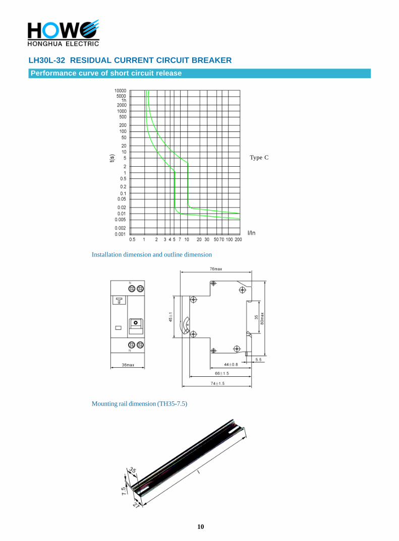
LH30L-32 RESIDUAL CURRENT CIRCUIT BREAKER
Performance curve of short circuit release
Installation dimension and outline dimension
Mounting rail dimension (TH35-7.5)
Type C
11
RESIDUAL CURRENT DEVICEUsage
Type OLL Residual Current Circuit Breaker without over current protection conforms to the standards of GB16916.1,IEC1008,BSEN61008etc.It is used in the circuits of AC 50~60HZ,single phase 230V(220V),three phases 400V(380V)in industrial&mining enterprises,Commercial buildings andhousing for protection of personal electric shock hazard and electric equipment and for unfrequent switchover of circuits under normal conditions.
Construction Characteristic & Operating Principle The RCD is electromagnetic current operating type,which consists of zero-phase current transformer(made of magnetic material),earth leakagetrip of high sensitivity,and operating mechanism and earth leakage test device.All components are integrated in a sealed moulded case. The earth leakage trip has several good merits,such as excellent appearance,advance in design,rational structure and reliable operation.By adoptinghigh quality material for tripping parts of operating structure and guaranteed by some patens,the earth leakage trip can withstand the vibration of 5gwithout trupping. The zero phase current transformer of earth leakage protection switch is used for examining the current vector difference value which flowsthrough the zero-phase current transformer.Meanwhile a relative output power produced on the secondary winding of zero-phase current transformeris added to the earth leakage trip,When,earth leakage of hazard occurs in the protected circuits,only leakage current of electric hazard current reachesor exceeds leakage operating current,the earth leakage trip may operate and make the swith to break the fault circuit,thus the protection for leakageof hazard is realized.
Normal Operation Conditions1. Ambient Air temperature:Ambient air temperature ranges from-540 ,not exceeding 35 averagely in 24 hours.2. Location:Installation location can not exceed 2000 meters above sea level.3. Air conditions:Relative humidity in the installation place can not exceed 50% when the air reaches the highest temperature40,the averageminimum temperature when it is the wettest can not exceed 25.Relative humidity not exceedint 90%.4. Installation Classfication:Installation is divided into grade grade .5. Installation Pollution Grade:Installation pollution grade is grade.6. Installation Type:It can be mounted with standard rail.7. Installation Conditions:Magnetic field outside the installation place can not exceed 5 times of the site of terrestrial magnetism in all direction.Normally speaking,RCCB should be mounted vetically.If the operation handle puts through power source upward,there should be no notable ompact andvibration in the installation place.8. Connection:It can be connected with screws or busbar.
NoticeLeakage protection function of RCD is tested and adjusted by the manufacturer,users can not open the product at random during usage.
After using RCD for a certain time(normally one month),test button should be pressed once in a state of making the circuit to chech whether the
function of RCD is normal and reliable(press test button once,the RCD can break off once).If abnormal,it should be unloaded and sent to the
manufacturer for repair.
RCD must not be wetted of soaked by rain,snow or water during the coures of transportation,storation and usage.
RCD can not play the role of protection when short circuit occurs.
Working priciple of RCD
P
M
RE
RB
tripping relay
mechanism of the RCD
earth resistance
wire resistance
Type And Meaning
OL L - / /
Pole
Rated residual operated current
Rated current
Design code
Residual current operated circuit
breaker
Enterprise code
Type and
secification
OLL
Mechanical
life (times)
Ratedconditionalshort circuitcurrent Im
10000
10000
3000A to
6000A
3000A to
6000A
Rated
operaitng
current (I n)
Residual
operaing
current range
Rated
voltage
Un
Rated
current
In
0.03A0.1A0.3A0.5A
0.03A0.1A0.3A0.5A
AC230V
AC400V
16A25A32A40A63A
16A25A32A40A63A80A
2 Pole
4 Pole
0.5I n~I n
0.5I n~I n
12
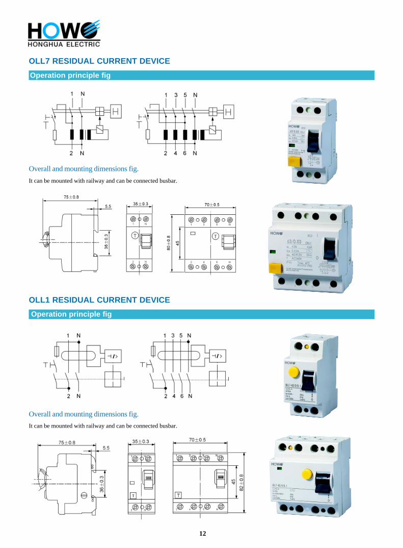
OLL7 RESIDUAL CURRENT DEVICE
OLL1 RESIDUAL CURRENT DEVICE
Operation principle fig
Operation principle fig
Overall and mounting dimensions fig.
It can be mounted with railway and can be connected busbar.
Overall and mounting dimensions fig.
It can be mounted with railway and can be connected busbar.
13
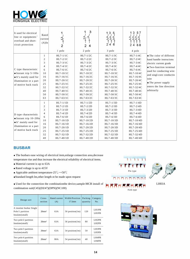
HL7-63 HIGH BREAKER CAPACITY MINI CIRCUIT BREAKER
Specification
Specification
Enclosure width
Mounting manner:
Terminal block capacity:
Terminal manner:
Electrical Specification
Conform to standard of electrical:
Rated current(Ue):
Rated breaking capacity:
Short circuit breaking capacity of DC:
Perfermance:
Max.fuse that can be connected to:
Working ambient temperature:
Enclosed protective class:
Electrical Life:
Selective grade:
Mechnical Life:
EN60898(IEC898) GB10963-99
230V/400V;50/60HZ
10KA IEC898(0.5~63A)
15KA IEC947-2(0.5~63A)
Max.48V(XYDB7...,10KA)single pole
Max.250V(XYDB7-DC,6KA)single pole
C,D charactisistic curve
100AgL(>10KA)
3
-5 to +40
P40(Under mounting)
Not less of 8000 times switching operation
Not less of 20000 times switching operation
The length of exposed plane:
Enclosure height:
45mm
80mm
17.5mm per pole(single pole)
35mm:1P+N(two pole)
Used for track of 35mm of IEC standard
Two-function terminal can connect with
bubar and conducting wire
Wire 1-25mm2
Conducting wire 0.8-2mm
Except extra declaration,two pole (1P+N)switch is two modular width,four Pole(3P+N)is
HX8 series modulus terminal box is applicable to the single-phase three-wire or
three-phase five-wire terminal circuit of AC 50/60HZ,rated voltage 230/400V,
current with load 100A or less. It is used to distribute and control the electrical
equipments, to protect the line from overload, short circuit, and leakage .It can be
widely applied in such modern construction occasions as hotel, hospital, residential
building and tall structure, etc.
The product is in conformity with
The standards:
GB/14048.1
IEC 60947-1
Classification
According to the installation form:
-flush type
-open-installation
According to number of circuit units:
-4 units
-6 units
-8 units
-12 units
-15 units
HX8
HX8M
Model meaning and classification
Model meaning
H X 8 -
Number of circuit units
H: Factory code
X: Terminal box
8:Design sequence No.
Installation form: no code for flush type
M: open –installation
Material code of box: no code for plastic box doby
J : metal base H: stainless steel base
17
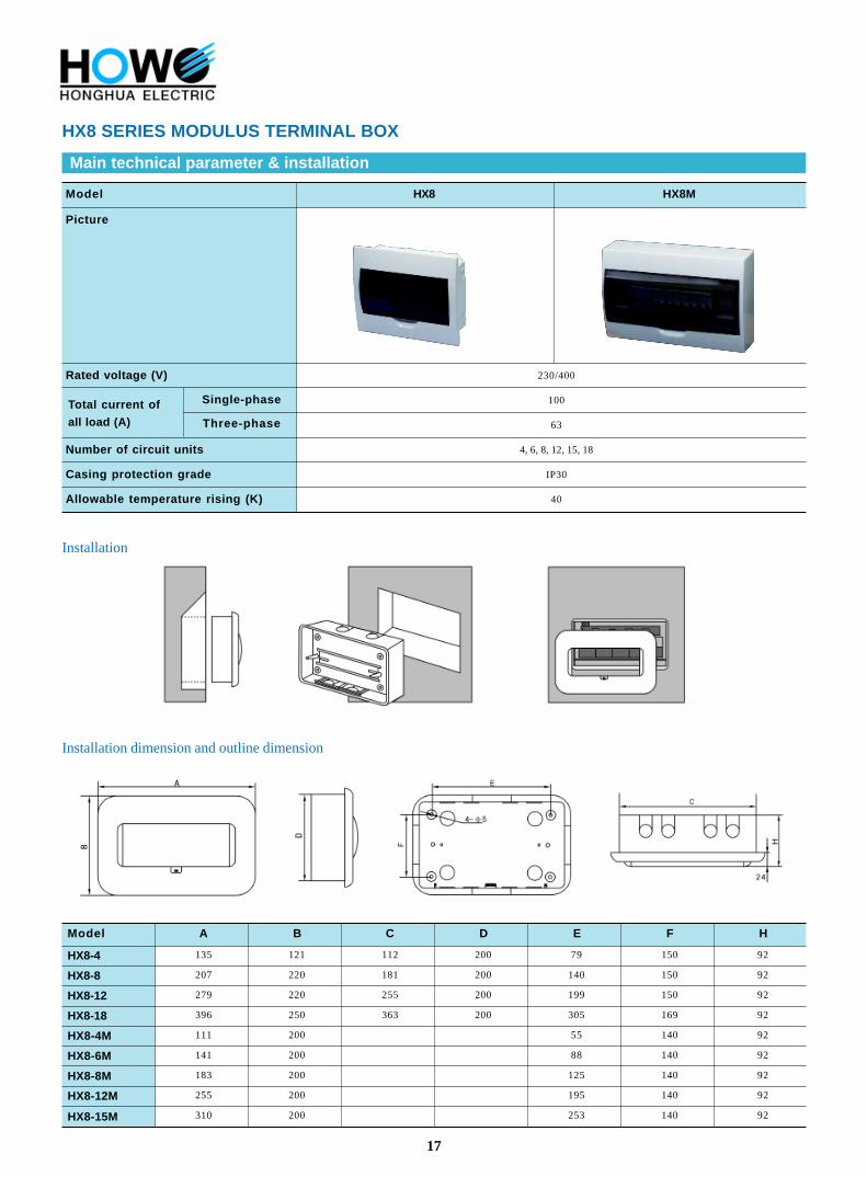
HX8 SERIES MODULUS TERMINAL BOX
Main technical parameter & installation
Model HX8
Picture
Installation
Installation dimension and outline dimension
230/400
100
63
4, 6, 8, 12, 15, 18
IP30
40
Rated voltage (V)
Total current of
all load (A)
Number of circuit units
Casing protection grade
Allowable temperature rising (K)
Single-phase
Three-phase
HX8M
Model A B C D E F H
HX8-4 135 121 112 200 79 150 92
HX8-8 207 220 181 200 140 150 92
HX8-12 279 220 255 200 199 150 92
HX8-18 396 250 363 200 305 169 92
HX8-4M 111 200 55 140 92
HX8-6M 141 200 88 140 92
HX8-8M 183 200 125 140 92
HX8-12M 255 200 195 140 92
HX8-15M 310 200 253 140 92
18
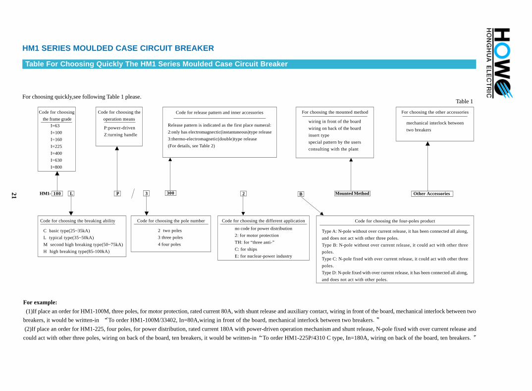
MCB SERIES FLUSH DISTRIBUTION BOX
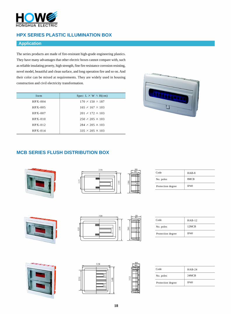
HPX SERIES PLASTIC ILLUMINATION BOX
Application
The series products are made of fire-resistant high-grade engineering plastics.
They have many advantages that other electric boxes cannot compare with, such
as reliable insulating proerty, high strength, fine fire resistance corrosion resisting,
novel model, beautiful and clean surface, and long operation fire and so on. And
their color can be mixed at requirements. They are widely used in housing
construction and civil electricity transformation.
Item
HPX-004
HPX-005
HPX-007
HPX-010
HPX-012
HPX-014
Spec: L W H(cm)
170 150 187
165 167 103
201 172 103
250 205 103
284 205 103
335 205 103
Protection degree
No. poles
Code
IP40
HAB-8
8MCB
Protection degree
No. poles
Code
IP40
HAB-12
12MCB
Protection degree
No. poles
Code
IP40
HAB-24
24MCB
19
Application Range
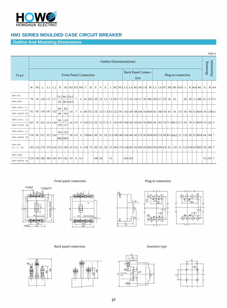
HM1 SERIES MOULDED CASE CIRCUIT BREAKER
HM1 and CM1 TM30 SM30 series moulded case breakers (hereafter
refered simply as breakers) are one of the new type breakers which have been
developed by the plant using international advanced design and manufacturing
technology. The rated insulation voltage of the breakers is 660V, suitable for turn-
on or turn-off not frequently and starting a motor not frequently in the circuit of
AC50Hz,rated working voltage 380V or below, rated working current up to 800A.
The breakers have overload, short-circuit and under-voltage protection devices, so
as to protect the circuit and the power equipment against damage.
The breakers,according to the rated maximum value of short circuit breaking
ability(lcu), could be classified into four kinds: types C(basic type), L(typical
type), M(second high breaking type) and H((high breaking type). The breakers
are of the following characteristics: compact size, high breaking ability, short arc-
over distance (some of the 0 arc-over distance) and shakeproof. Furthermore
the ideal products applied on land or ships.
- The breakers could be installed vertically (upright)or horizontally (transverse).
- The breakers comply with the demands of the following standards:
IEC 947-1 and GB/T 14048.1 General
IEC 947-2 and GB 14048.2 Low voltage breakers
IEC 947-4 and GB 14048.4 Contactors and motor starters
IEC 947-5 and GB 14048.5 Electrical equipments of electromechanical control
circuit
Applicable Environment Condition
Elevation 2000m.
Ambient temperature:+40 (45 for ships)~-5 .
Be able to bear the influence of moisture in the air.
Be able to bear the influence of salt fog and oil fog.
Be able to bear the influence of mould.
Be able to bear the influence of nuclear radiation.
The gradient 22.5
Be working reliably under the condition of normal vibration on ship.
Be working reliably when earthquake (4g) occurs.
There must be no explosive medium, and there must be no gas which would
corrode metal or any conducting dust which would destroy the insulation.
The place would not be invaded by rain and snow.
20
Note:
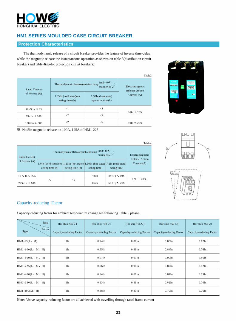
HM1 SERIES MOULDED CASE CIRCUIT BREAKER
Types And Meanings
No code for current distribution, 2 means for motor protection.
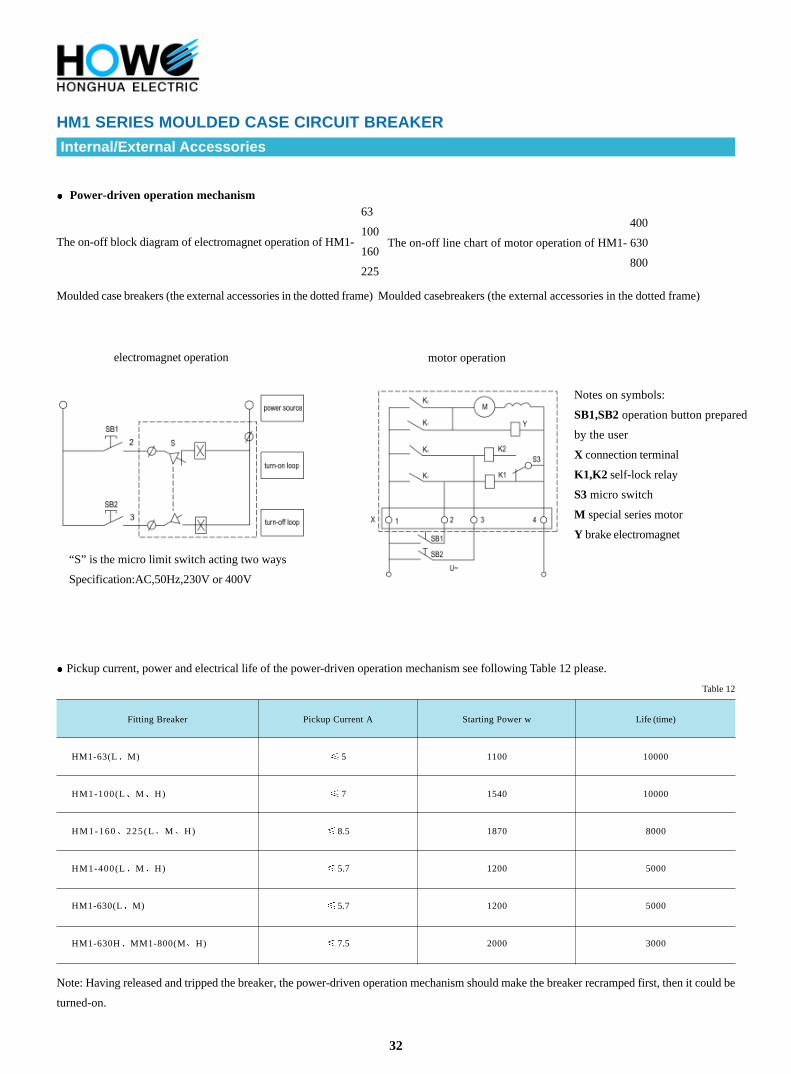
No code for operating directly with handle, P for power-driven and Z for turning handle manually.
According to the pole number of product, it classifies two-poles (100A, 225A),three-and four-poles (no four-poles type for HM1-800). The
neutral pole (N-pole) of the four-poles products has four types:
Type A: N-pole without over-current release unit, it has been connected all along, and does not act with other three poles to turn on or off.
Type B: N-Pole without over-current release unit, it could act with other three poles.(N-pole turns-on prior to turns-off.)
Type C: N-pole fixed with over-current release unit, it could act with other three poles. (N-pole turns-on prior to turns-off.)
Type D: N-pole fixed with over-current release unit, it has been connected all along, and does not act with other three poles to turn on or off.
Classification according to rated current (A): HM1-63 has nine grades:(6)10 16 20 25 32 40 50 63A (6A without
over-load protection); HM1-100 has ten:(10)16 20 25 32 40 50 63 80 100A;HM1-160 has four;100 125 140
160; HM1-225 has seven:100 25 140 160 180 200 225A; HM1-400 has five:225 250 315 350 400A; HM1-
630 has three:400500 630A; and HM1-800 has three:630700 800A [specifications in brackets is not recommend.]
The wiring method has three ways:wiring in front of the board, wiring on back of the board and insertion type.
According to the over-current release pattern, it would be divided into two types: thermo-electromagnetic (double) type and electro magnetic
(instantaneous)type.
According to the outfit, it also has two types:
With or without outfit. the outfit include inner accessories and outside accessories:
The inner accessories have shunt release, under-voltage release, auxiliary contact and alarm contacts four kinds. The outside accessories are
turning handle operation mechanism, power-driven operation mechanism, interlocking mechanism and the services wiring contact.
H M 1 - /
Application code
Methods of release and accessory code
(see table1)
Pole number
Operating method
Breaking capacity grade of rated limiting
short-circuit
Rated current of frame
Design code
Moulded case circuit breaker
21
For example:
(1)If place an order for HM1-100M, three poles, for motor protection, rated current 80A, with shunt release and auxiliary contact, wiring in front of the board, mechanical interlock between two
breakers, it would be written-in To order HM1-100M/33402, In=80A,wiring in front of the board, mechanical interlock between two breakers
(2)If place an order for HM1-225, four poles, for power distribution, rated current 180A with power-driven operation mechanism and shunt release, N-pole fixed with over current release and
could act with other three poles, wiring on back of the board, ten breakers, it would be written-inTo order HM1-225P/4310 C type, In=180A, wiring on back of the board, ten breakers
Table 1
Code for choosing the four-poles product
Type A: N-pole without over current release, it has been connected all along,
and does not act with other three poles.
Type B: N-pole without over current release, it could act with other three
poles.
Type C: N-pole fixed with over current release, it could act with other three
poles.
Type D: N-pole fixed with over current release, it has been connected all along,
and does not act with other poles.
For choosing the other accessories
mechanical interlock between
two breakers
For choosing quickly,see following Table 1 please.
Code for choosing
the frame grade
For choosing the mounted method
wiring in front of the board
wiring on back of the board
insert type
special pattern by the users
consulting with the plant
Code for release pattern and inner accessories
Release pattern is indicated as the first place numeral:
2:only has electromagnectic(instantaneous)type release
3:thermo-electromagnetic(double)type release
(For details, see Table 2)
Code for choosing the
operation means
P:power-driven
Z:turning handle
L P 3 300 2 B Mounted Method Other Accessories
Table For Choosing Quickly The HM1 Series Moulded Case Circuit Breaker
HM1 SERIES MOULDED CASE CIRCUIT BREAKER
Code for choosing the breaking ability
C basic type(25~35kA)
L typical type(35~50kA)
M second high breaking type(50~75kA)
H high breaking type(85-100kA)
Code for choosing the pole number
2 two poles
3 three poles
4 four poles
Code for choosing the different application
no code for power distribution
2: for motor protection
TH: for “three anti-”
C: for ships
E: for nuclear-power industry
I=63
I=100
I=160
I=225
I=400
I=630
I=800
100HM1-
22
Release Pattern And Accessories Code
Release pattern and accessories code see following Table 2 please.Alarm contact
Auxiliary contact
Shunt release
Under-voltage release
Lead direction
Table 2
Note:
200:breaker only has electromagnetic release pattern 300: breaker has thermo-electromagnetic release pattern 000:breaker without release
pattern;
For HM1-100 225 two-poles type, only has following accessories code:210310 220 320 230 330 For HM1-63
100and HM1-160 225 Fourpoles breaker of N-pole types A & D, only has the following accessories codes:240340 260 360
2 1 8 3 1 8 2 4 8 3 4 8 2 6 8 3 6 8
For HM1-400 HM1-630 and HM1-800,codes 248348 278 378 only have one pair of auxiliary contacts (a normal opened, a
normal closed),but 268368 have three pairs of auxiliary contacts.


![Index [3.imimg.com] · Index Miniature Circuit Breaker 2 Residual Current Circuit Breaker (RCCB) 16A - 63A 36 Miniature Circuit Breaker (80A - 125A) 18 ... until it operates a latching](https://static.documents.pub/doc/80x56/5e8f8e0a5f8a0f4fe028da5f/index-3imimgcom-index-miniature-circuit-breaker-2-residual-current-circuit-breaker.jpg)


