This NORSOK standard is developed with broad petroleum industry participation by interested parties in the Norwegian petroleum industry and is owned by the Norwegian petroleum industry represented by The Norwegian Oil Industry Association (OLF), The Federation of Norwegian Industry, Norwegian Shipowners’ Association and The Petroleum Safety Authority Norway. Please note that whilst every effort has been made to ensure the accuracy of this NORSOK standard, neither OLF nor The Federation of Norwegian Industry or any of their members will assume liability for any use thereof. Standards Norway is responsible for the administration and publication of this NORSOK standard. Standards Norway Telephone: + 47 67 83 86 00 Strandveien 18, P.O. Box 242 Fax: + 47 67 83 86 01 N-1326 Lysaker Email: [email protected]NORWAY Website: www.standard.no/petroleum Copyrights reservedNORSOK STANDARD E-001 Draft for Edition 5, March 2006 Electrical systems
Transcript
8/9/2019 E-001de5
http://slidepdf.com/reader/full/e-001de5 1/54
This NORSOK standard is developed with broad petroleum industry participation by interested parties in theNorwegian petroleum industry and is owned by the Norwegian petroleum industry represented by The NorwegianOil Industry Association (OLF), The Federation of Norwegian Industry, Norwegian Shipowners’ Association andThe Petroleum Safety Authority Norway. Please note that whilst every effort has been made to ensure the accuracyof this NORSOK standard, neither OLF nor The Federation of Norwegian Industry or any of their members willassume liability for any use thereof. Standards Norway is responsible for the administration and publication of this
NORSOK STANDARD E-001Draft for Edition 5, March 2006
Electrical systems
8/9/2019 E-001de5
http://slidepdf.com/reader/full/e-001de5 2/54
8/9/2019 E-001de5
http://slidepdf.com/reader/full/e-001de5 3/54
NORSOK standard E-001 Draft for Edition 5, March 2006
NORSOK standard Page 1 of 50
Foreword 3
Introduction 3
1 Scope 4
2 Normative and informative references 4
2.1 Normative references 4
2.2 Informative references 6 3 Terms, definitions and abbreviations 6
3.1 Terms and definitions 6
3.2 Abbreviations 6
4 General requirements and conditions (see IEC 61892-1) 7
4.1 General (see IEC 61892-1, 4.1) 7
4.2 Acceptance of substitutes or alternatives (see IEC 61892-1, 4.4) 7
4.3 Environmental conditions (see IEC 61892-1, 4.7) 7
4.4 Materials 7
4.5 Power supply system characteristics (see IEC 61892-1, 4.9) 7
4.6 Electrical apparatus for explosive gas atmospheres (see IEC 61892-1, 4.10) 8
4.7 Clearance and creepage distances (see IEC 61892-1, 4.12) 8
4.8 Insulation (see IEC 61892-1, 4.13) 8 4.9 Maintenance and inspection (see IEC 61892-1, 4.14) 8
4.10 Cable entries (see IEC IEC 61892-1, 4.15) 8
4.11 Location of electrical equipment in units (see IEC 61892-1, 4.17) 8
4.12 Spaces and compartments (see IEC 61892-1, 4.18) 9
4.13 Spare requirements for future modifications 9
4.14 Mechanical protection (see IEC 61892-1, 4.19) 9
4.15 Protection from heat, water, steam and oil (see IEC 61892-1, 4.20) 9
5 System design (see IEC 61892-2) 9
5.1 Sources of electrical power (see IEC 61892-2, Clause 4) 9
5.2 System earthing (see IEC 61892-2, Clause 5) 13
5.3 Distribution systems (see IEC 61892-2, Clause 6) 15
5.4 Distribution system requirements (see IEC 61892-2, Clause 7) 16
5.5 Diversity (demand) factors (see IEC 61892-2, Clause 8) 16
5.6 System study and calculations (see IEC 61892-2, Clause 9) 16
5.7 Protection (see IEC 61892-2, Clause 10) 18
5.8 Lighting (see IEC 61892,2, Clause 11) 20
5.9 Control and instrumentation (see IEC 61892-2, Clause 12) 21
5.10 Degrees of protection by enclosures (see IEC 61892-2, Clause 13) 22
6 Equipment (see IEC 61892-3) 22
6.1 General 22
6.2 Generators and motors (see IEC 61892-3, Clause 4) 22
6.3 Transformers for power and lighting (see IEC 61892-3, Clause 5) 25
6.4 Switchgear and control gear assemblies (see IEC 61892-3, Clause 6) 27
6.5 Electrical indicating instruments 29
6.6 Semiconductor convertors (see IEC 61892-3, Clause 7) 30 6.7 Secondary cells and batteries (UPS) (see IEC 61892-3, Clause 7 and Clause 8) 35
6.8 Luminaires (see IEC 61892-3, Clause 9) 36
6.9 Heating and cooking appliances (see IEC 61892-3, Clause 10) 36
6.10 Trace and surface heating (see IEC 61892-3, Clause 11) 36
6.11 Communication (see IEC 61892-3, Clause 12) 36
6.12 Underwater systems and appliances (see IEC 61892-3, Clause 13) 36
6.13 Control and instrumentation (see IEC 61892-3, Clause 14) 36
6.14 Accessories (see IEC 61892-3, Clause 15) 37
7 Cables (see IEC 61892-4) 37
8 Mobile units (see IEC 61892-5) 38
8.1 General 38
8.2 Limits of inclination of the unit (see IEC 61892-5, Clause 5) 38
9 Installation (see IEC 61892-6) 38
8/9/2019 E-001de5
http://slidepdf.com/reader/full/e-001de5 4/54
NORSOK standard E-001 Draft for Edition 5, March 2006
NORSOK standard Page 2 of 50
9.1 Equipment earthing and bonding (see IEC 61892-6, Clause 4) 38
9.2 Cables and wiring (see IEC 61892-6, Clause 5) 39
9.3 Generators and motors (see IEC 61892-6, Clause 6) 43
9.4 Transformers (see IEC 61892-6, Clause 7) 43
9.5 Switchgear and control gear assemblies (see IEC 61892-6, Clause 8) 43
9.6 Secondary cells and batteries (see IEC 61892-6, Clause 10) 43
9.7 Luminaires (see IEC 61892-6, Clause 11) 43
9.8 Trace and surface heating (see IEC 61892-6, Clause 13) 44
9.9 Lightning protection (see IEC 61892-6, Clause 16) 44
9.10 Test of completed installation (see IEC 61892-6, Clause 17) 44
9.11 Documentation (see IEC 61892-6, Clause 18) 44
9.12 Marking and labelling 44
9.13 Bulk materials 46
10 Hazardous areas (see IEC 61892-7) 47
10.1 General 47
10.2 Electrical systems (see IEC 61892-7, Clause 5) 47
10.3 Electrical equipment (see IEC 61892-7, Clause 6) 47
10.4 Installation (see IEC 61892-7, Clause 7) 48
10.5 Documentation (see IEC 61892-7, Clause 10) 48
Annex A (Normative) Data sheets 49
Bibliography 50
8/9/2019 E-001de5
http://slidepdf.com/reader/full/e-001de5 5/54
NORSOK standard E-001 Draft for Edition 5, March 2006
NORSOK standard Page 3 of 50
Foreword
The NORSOK standards are developed by the Norwegian petroleum industry to ensure adequate safety,value adding and cost effectiveness for petroleum industry developments and operations. Furthermore,NORSOK standards are, as far as possible, intended to replace oil company specifications and serve as
references in the authorities’ regulations.
The NORSOK standards are normally based on recognised international standards, adding the provisionsdeemed necessary to fill the broad needs of the Norwegian petroleum industry. Where relevant, NORSOKstandards will be used to provide the Norwegian industry input to the international standardisation process.Subject to development and publication of international standards, the relevant NORSOK standard will bewithdrawn.
The NORSOK standards are developed according to the consensus principle generally applicable for moststandards work and according to established procedures defined in NORSOK A-001.
The NORSOK standards are prepared and published with support by The Norwegian Oil Industry Association(OLF), The Federation of Norwegian Industry, Norwegian Shipowners’ Association and The Petroleum SafetyAuthority Norway.
NORSOK standards are administered and published by Standards Norway.
Annex A is normative.
Introduction
This NORSOK standard is based on equipment and practices which are in current use, but it is not intendedin any way to impede development of new or improved techniques.
8/9/2019 E-001de5
http://slidepdf.com/reader/full/e-001de5 6/54
NORSOK standard E-001 Draft for Edition 5, March 2006
NORSOK standard Page 4 of 50
1 Scope
This NORSOK standard contains provisions for electrical installations at all voltages and is intended to enablesafety in the design of electrical systems, selection, and use of electrical equipment for generation, storage,distribution and utilization of electrical energy for all purposes in offshore units which are being used for the
purpose of exploration or exploitation of petroleum resources.
This NORSOK standard does not apply for the electrical installations in rooms used for medical purposes orin tankers.
Each clause in this NORSOK standard refers to the equivalent clause in the IEC 61892 series of standards.
This NORSOK standard applies to all installations. The installation may be permanent, temporary,transportable or hand-held, to AC installations up to and including 35 000 V and DC installations up to andincluding 1 500 V.
NOTE This NORSOK standard is applicable for the voltages stated above, even if a different voltage limit may be given in some of theparts in the IEC 61892 series of standards. It is expected that the voltage levels in the IEC 61892 series of standards will be correctedas part of the maintenance cycle of this IEC standard.
2 Normative and informative references
The following standards include provisions and guidelines which, through reference in this text, constituteprovisions and guidelines of this NORSOK standard. Latest issue of the references shall be used unlessotherwise agreed. Other recognized standards may be used provided it can be shown that they meet orexceed the requirements and guidelines of the standards referenced below.
2.1 Normative references
DBE-9039, Retningslinjer for jording i maritime anleggDirective 94/9/EC, ATEX
NOTE Implemented in Norway by “Forskrift om utstyr og sikkerhetssystem til bruk I eksplosjonsfarligområde (FUSEX)”.
NOTE Implemented in Norway by ”Forskrift om maskiner”
EN 1838, Lighting application – Emergency lightingEN ISO 13702, Petroleum and natural gas industries - Control and mitigation of fires and
explosions on offshore production installations - Requirements and guidelinesIEC 60034-1, Rotating electrical machines – Part 1: Rating and performanceIEC 60034-8, Rotating electrical machines – Part 8: Terminal markings and direction of rotationIEC 60034-9, Rotating electrical machines – Part 9: Noise limitsIEC 60034-14, Rotating electrical machines – Part 14: Mechanical vibration of certain machines
with shaft heights 56mm and higher. Measurement, evaluation and limits of thevibration severity
IEC 60076-1, Power transformers – Part 1: General
IEC 60146-1-1, Semiconductor convertors - General requirements and line commutated convertors – Part 1-1: Specifications of basic requirements
IEC 61000-2-4, Electromagnetic compatibility (EMC) – Part 2-4: Environment - Compatibility levelsin industrial plants for low-frequency conducted disturbances
IEC 61800-4, Adjustable speed electrical power drive systems - Part 4: General requirements -Rating specifications for a.c. power drive systems above 1 000 V a.c. and notexceeding 35 kV
IEC 61892, Mobile and fixed offshore units – Electrical installations – (all parts)IEC 62040-3, Uninterruptible power systems (UPS) – Part 3: Method of specifying the
performance and test requirementsIEC 62271-200, High-voltage switchgear and controlgear – Part 200: A.C. metal-enclosed
switchgear and controlgear for rated voltages above 1 kV and up to and including52 kV
IMO 1989 MODU Code, Code for construction and equipment of mobile offshore unitsNORSOK T-001, Telecommunication systemsNORSOK T-100, Telecom subsystems
8/9/2019 E-001de5
http://slidepdf.com/reader/full/e-001de5 7/54
NORSOK standard E-001 Draft for Edition 5, March 2006
-Forskrifter for merking av innretninger i petroleumsvirksomheten (Guidelinesrelating to marking of installations in the petroleum activities)
Forskrift for sikkerhet ved arbeid i og drift av høyspenningsanlegg(BSL) D5-1, Bestemmelser for sivil luftfart (Luftfartsverket)SOLAS 1974regulation 42/43, Code for the construction and equipment of mobile offshore drilling units, 1989.
Chapter 5 (MODU CODE 1989),
Trace heating guidelines in Industry and Offshore (IFEA)EN 13463-1, Non-electrical equipment for potentially explosive atmospheres. Basic method and
requirementsEN 50020, Electrical apparatus for potentially explosive atmospheres - Intrinsic safety 'i'EN 50091-1, Uninterruptable power systems (UPS) - Part 1: General and safety requirementsEN 50091-2, Uninterruptable power systems (UPS) - Part 2: EMC requirementEN 50272-2. Safety requirements for secondary batteries and battery installations - Part 2:
Stationary batteriesIEC 60034, Rotating electrical machines – (all parts)IEC 60073, Basic and safety principles for man-machine interface, marking and identification –
Coding principles for indication devices and actuatorsIEC 60079-0, Electrical apparatus for explosive gas atmospheres – Part 0: General requirementsIEC 60079-1, Electrical apparatus for explosive gas atmospheres – Part 1: Flameproof enclosure
'd'IEC 60079-2, Electrical apparatus for explosive gas atmospheres – Part 2: Pressurized apparatus
"p"IEC 60079-7, Electrical apparatus for explosive gas atmospheres – Part 7: Increased safety 'e'IEC 60079-17, Electrical apparatus for explosive gas atmospheres – Part 17: Inspection and
maintenance of electrical installations in hazardous areas (other than mines)IEC 60079-19, Electrical apparatus for explosive gas atmospheres – Part 19: Repair and overhaul
for apparatus used in explosive atmospheres (other than mines or explosives)IEC 60146-1-3, Semiconductor converters – General requirements and line commutated converters
– Part 1-3: Transformers and reactors.IEC 60439-1, Low-voltage switchgear and controlgear assemblies - Part 1: Type-tested and
partially type-tested assembliesIEC 60502-2, Power cables with extruded insulation and their accessories for rated voltages from
1 kV (Um=1.2 kV) up to 30 kV (Um=36 kV) – Part 2: Cables for rated voltages from6 kV (Um=7.2 kV) up to 30 kV (Um=36 kV)
IEC 60726, Dry - type power transformersIEC 60947-4-1, Low voltage switchgear and control gear - Part 4-1: Contactors and motor-starters
Section one - Electromechanical contactors and motor-startersIEC 61800-3, Adjustable speed electrical power drive systems - Part 3: EMC requirements and
specific test methodsIEC 61892-1, Mobile and fixed offshore units - Electrical installations - Part 1: General
requirements and conditionsIEC 61892-2, Mobile and fixed offshore units - Electrical installations - Part 2: System designIEC 61892-3, Mobile and fixed offshore units - Electrical installations - Part 3: EquipmentIEC 61892-4, Mobile and fixed offshore units - Electrical installations - Part 4: CablesIEC 61892-5, Mobile and fixed offshore units - Electrical installations - Part 5: Mobile unitsIEC 61892-6, Mobile and fixed offshore units - Electrical installations - Part 6: InstallationIEC 61892-7, Mobile and fixed offshore units - Electrical installations - Part 7: Hazardous areasNORSOK Z-DP-002, Coding system
Guidelines for the documentation of selectivity (discrimination) in a.c. systems (IFEA)Directive 89/336/EC, EU directive for EMCNEK 606, Cables for offshore installations Halogen-free, or mud resistantNORSOK I-002, Safety and automation systems (SAS)NORSOK S-001, Technical safetyNORSOK Z-015 Temporary equipment
8/9/2019 E-001de5
http://slidepdf.com/reader/full/e-001de5 8/54
NORSOK standard E-001 Draft for Edition 5, March 2006
NORSOK standard Page 6 of 50
2.2 Informative references
IEC 60092-504, Electrical installation in ships – Part 504: Special features - Control andinstrumentation
3 Terms, definitions and abbreviations
For the purposes of this NORSOK standard, the following terms, definitions and abbreviations apply.
3.1 Terms and definitions
3.1.1shallverbal form used to indicate requirements strictly to be followed in order to conform to this NORSOK standardand from which no deviation is permitted, unless accepted by all involved parties
3.1.2shouldverbal form used to indicate that among several possibilities one is recommended as particularly suitable,without mentioning or excluding others, or that a certain course of action is preferred but not necessarilyrequired
3.1.3mayverbal form used to indicate a course of action permissible within the limits of this NORSOK standard
3.1.4canverbal form used for statements of possibility and capability, whether material, physical or casual
3.2 Abbreviations
AC alternating currentAF forced air cooledAN naturally air cooled
ASDS adjustable speed drive systemATEX Atmosphere EXplosibleAVR automatic voltage regulatorBDM basic drive moduleBSL Bestemmelse for sivil luftfartCENELEC European Committee for Electrotechnical StandardizationDC direct currentDOL direct on lineDu/Dt high frequency harmonic filterEMC electromagnetic compatibilityESD emergency shut downEU European UnionEx explosion proof
FCR field current regulatorHV high voltage, U≥1kVIE Instrument earthIEC International Electrotechnical CommisionIFEA Industriens Forening for Elektroteknikk og AutomatiseringI/O input/outputIP international protectionIS intrinsically safeISO International Organization for StandardizationIT isolated power systemLCI load commutated inverterLV low voltage, U<1kVMCC motor control centre
MCT multi cable transitNEK Norsk Elektroteknisk KomitePCS process control system
8/9/2019 E-001de5
http://slidepdf.com/reader/full/e-001de5 9/54
NORSOK standard E-001 Draft for Edition 5, March 2006
NORSOK standard Page 7 of 50
PCC point of common connectionPE protective earthPDCS power distribution control systemPDS power drive systemPtil PetroleumstilsynetRTD resistor temperature detectorSAS safety and automation systemsTEFC totally enclosed fan colledTHD total harmonic voltage distortionTN-S directly earthed, a separate protective conductor is usedUPS uninterruptible power systemVDU visual display unit
4 General requirements and conditions (see IEC 61892-1)
4.1 General (see IEC 61892-1, 4.1)
In addition to the requirements of IEC 61892, the following EU directives shall be complied with:
• Directive 89/336/EC;
• Directive 94/9/EC;• Directive 98/37/EC;
• Directive 73/23/EC.
4.2 Acceptance of substitutes or alternatives (see IEC 61892-1, 4.4)
If equipment, construction or arrangement not specified in this NORSOK standard is used, compliance withrelevant Ptil regulations is to be documented.
NOTE The use of this NORSOK standard will normally ensure compliance with the Ptil Regulations.
In the event of other solutions being used than those recommended in the comments to a provision containedin the Ptil regulations, the party responsible shall be able to provide documentary proof that the solutionchosen fulfils the requirements of the regulations. To obtain the best possible understanding of the level thatit is desired to achieve through the regulations, the regulations and the comments need to be viewedcollectively. Norms that are recommended in the comments will be central factors in interpreting the individualrequirements of regulations and when establishing the level for health, working environment and safety.
Combinations of parts of norms should be avoided, unless the party responsible is able to document that anequivalent level in relation to health, working environment and safety is achieved.
4.3 Environmental conditions (see IEC 61892-1, 4.7)
Unless otherwise specified for the relevant project, the following ambient temperatures shall be used as abasis:
Ambient outdoor air temperature: minimum -5 °C, maximum 25 °C
Sea water temperature: minimum 5 °C, maximum 15 °C
4.4 Materials
All equipment and materials shall have low halogen content.
Equipment enclosures located outdoor, in naturally ventilated areas and wash down areas, shall be made ofproven sea water resistant material or protected by a coating system according to NORSOK M-501.,Electrical/electronic equipment in panels shall be protected against hydraulic leakage.
4.5 Power supply system characteristics (see IEC 61892-1, 4.9)
For harmonic distortion (voltage waveform) (see IEC 61892-1, 4.9.2.2)the detailed harmonic voltage acceptance limits shall correspond to IEC 61000-2-4, class 2, for any voltage,
except that the fifth harmonic shall not exceed 5 %.
8/9/2019 E-001de5
http://slidepdf.com/reader/full/e-001de5 10/54
NORSOK standard E-001 Draft for Edition 5, March 2006
NORSOK standard Page 8 of 50
To ensure EMC (electromagnetic compatibility) between equipment it is important that the emission from onecomponent do not exceed the susceptibility level of other equipment. For complex installations, an EMCanalysis should be performed to detect if additional measures (shielding/filtering) is required to ensure thatEMC is achieved between all equipment.
4.6 Electrical apparatus for explosive gas atmospheres (see IEC 61892-1, 4.10)
Electrical equipment required to be suitable for installation in hazardous areas shall comply with the
requirements of the Norwegian ”Forskrift om utstyr og sikkerhetssystem til bruk i eksplosjonsfarlig område”.
4.7 Clearance and creepage distances (see IEC 61892-1, 4.12)
Table 1 is not applicable for type approved equipment. The following minimum creepage distances shall bemet for not approved equipment, and if any site modifications to type approved equipment shall be made.
Table 1 – Creepage distances
Nominal voltage Creepage distances, IEC60439-1, Pollution degree
4.9 Maintenance and inspection (see IEC 61892-1, 4.14)
Equipment shall be designed to allow for thermographic on load inspection or use of thermostrips, wherepossible. For equipment like power transformer, UPS, switchgear and motor control centre, should bearranged where possible.
4.10 Cable entries (see IEC IEC 61892-1, 4.15)
In addition to environmental conditions, the cable entries shall maintain the required protection with respect toconducted EMC.
4.11 Location of electrical equipment in units (see IEC 61892-1, 4.17)Electrical equipment rooms shall be used for major electrical equipment.
Doors to high voltage rooms shall open out from the room. Hinged doors shall be provided with “panicopening device” which can be opened without using the hands.
For battery room reference is made to EN 50272-2.
In order to avoid installation of major electrical equipment in hazardous areas or in exposed environments, allmajor electrical equipment shall be installed inside equipment rooms with a controlled atmosphere.
All power supply and control equipment for foghorn and navigational lights shall be located indoors at alocation suitable for maintenance activities. The integrated power supplies shall be galvanically isolated from
the mains.
8/9/2019 E-001de5
http://slidepdf.com/reader/full/e-001de5 11/54
NORSOK standard E-001 Draft for Edition 5, March 2006
NORSOK standard Page 9 of 50
Location of electrical equipment shall be selected to avoid interference with escape routings, walkways, otherequipment, pipes etc. and obstruction against activities related to transport and lifting operations.
Equipment should not be supported on pipe work, handrails, access ladders or cable ladders. Lightingfixtures may, however, be mounted underneath cable ladders or as integrated part of handrail supportarrangement.
Equipment such as public address flashing lights, loudspeakers, junction boxes, splitters and tap-off, may belocated on the support for cable ladders and trays or on the side rail of the cable ladders.
Equipment shall not be mounted on blastwalls/explosion relieves. Equipment can, however, be installed onthe support frames for the blast walls if the integrity of the blast wall is not interfered.
Equipment located in areas which do not allow for maintenance accessibility as required, should as shown ontypical drawing be installed such that the equipment can be rotated, raised or lowered into areas wheremaintenance can take place without the need for scaffolding.
4.12 Spaces and compartments (see IEC 61892-1, 4.18)
Spaces in which engine driven generating sets are located shall comply with the requirements of the Ptilregulations.
NOTE Regarding separation of main and emergency power and fire divisions for rooms containing electrical equipment, reference ismade to the Facilities Regulations, sections 29 and 37.
4.13 Spare requirements for future modifications
The requirements are related to spare at the time of plant start-up.
The installation should be prepared for
• relevant area interface cabinets, junction boxes, cabling etc. to meet a 10 % increase,
• main cable ladders to meet a 10 % increase.
4.14 Mechanical protection (see IEC 61892-1, 4.19)
Special attention to protection of electrical equipment against mechanical damage shall be given in storageand loading areas.
4.15 Protection from heat, water, steam and oil (see IEC 61892-1, 4.20)
Full scale testing of deluge system may take place. Selection and installation of equipment should be suchthat adverse effects to the equipment due to testing is minimised.
Equipment located in areas where deluge testing will take place shall have degree of protection at least IP 56.
5 System design (see IEC 61892-2)
5.1 Sources of electrical power (see IEC 61892-2, Clause 4)
5.1.1 General (see IEC 61892-2, 4.1)
See IEC 61892-2, 4.1.4 For further detailed requirements concerning voltage drop at various parts of the electrical system, seeadditional requirements in chapter 5.6.6 “Cable selection and sizing criteria”.
5.1.2 Main source of electrical power (see IEC 61892-2, 4.2)
See IEC 61892-2, 4.2.1 The main power supply shall serve all electrical functions during normal operation.
The main power supply may be arranged locally, with subsea cables from another offshore unit, from shoreor with a combination of the alternatives.
8/9/2019 E-001de5
http://slidepdf.com/reader/full/e-001de5 12/54
NORSOK standard E-001 Draft for Edition 5, March 2006
NORSOK standard Page 10 of 50
When local power generation is provided, the generators shall be grouped in a central power plant. The unitrating and number of generating sets shall be adapted to the load profile of the systems served over theentire lifetime of the unit.
The main power generator auxiliary consumers shall be supplied from both the main and the emergencysystem. If an essential source of power is available, these consumers shall be supplied from the main andthe essential system. A change over system shall be provided.
The configuration of the main power distribution system shall depend on the regularity requirements of theproduction process.
IEC 61892-2 requires at least two main generators. If one main generator can supply the total maximum loadat the plant, and the regularity requirements do not require “2 x 100 %”, the second generator can be anessential generator.See IEC 61892-2, 4.2.2 The regulations do not allow connecting other consumers than emergency consumers to the emergencyswitchboard. Therefore an essential power system with essential generator(s) should be evaluated. Criteriafor essential power system should be sufficient power for utilities necessary for accommodation (normalconditions of habitability), and power for turnaround periods. See additional requirement to 4.3.6.
5.1.3 Emergency source of power (see IEC 61892-2 4.3)See IEC 61892-2, 4.3.1 The emergency power supply system shall serve emergency power consumers as defined by Ptil.
The emergency power supply systems shall comprise a combination of UPS, and, if necessary, a dieselengine driven generator. Alternatively to diesel engine driven generator, power cable from anotherindependent plant may be considered.
The emergency power supply system shall be independent of the main supply systems. Main and emergencydistribution equipment shall be located in separate rooms. Sub distribution boards may be located in thesame room as main supply systems.
If the emergency power is supplied from a diesel driven emergency generator it shall be a capable of
supplying the consumers with emergency power for at least 18 h.
See IEC 61892-2, 4.3.2 See additional requirements to 4.7, 4.8 and 4.9. Efforts should be done to avoid dependence of seawater forcooling of the emergency generator prime-mover, hence air cooled prime mover should be used.
See IEC 61892-2, 4.3.3 Services required for the transitional source of electrical power are missing in 4.3.5. See additionalrequirement to 4.3.4.
See IEC 61892-2, 4.3.4 The requirements to the transitional source of power mentioned in 4.3.4 and the uninterruptible power supplysystem mentioned in 4.3.7 shall be fulfilled by the plants UPS system.
UPSs shall be provided for emergency services and non-emergency services requiring continuous AC or DCpower supply in case of main power failure blackout or electrical disturbances. Equipment sensitive toelectrical disturbances (e.g. voltage transients and harmonic distortion should be supplied from UPSs.
UPS power shall be provided for the following services:
• safety systems (emergency consumers);
• control systems required for operation and monitoring of safety auxiliary systems;• vital telecommunication systems;• control systems required for restarting of the drilling and production systems;
• control equipment liable to fail or malfunction upon occurrence of normally expected voltage transients,e.g., on starting of large induction motors;
• obstruction lights;• circuit breaker control voltage.
8/9/2019 E-001de5
http://slidepdf.com/reader/full/e-001de5 13/54
8/9/2019 E-001de5
http://slidepdf.com/reader/full/e-001de5 14/54
NORSOK standard E-001 Draft for Edition 5, March 2006
NORSOK standard Page 12 of 50
See IEC 61892-2, 4.4.3 Automatic starting and connection to the main switchboard of a stand-by generating set is only required foroffshore units depending on thrusters, propulsion and steering. Stand-by generator set can be essentialgenerator(s) as described in requirements to 4.2.2.
See IEC 61892-2, 4.4.4 The requirement for automatic re-starting only applies to consumers where prolonged disconnection will
cause serious damage, reduced safeguarding, or extended shutdown.
See IEC 61892-2, 4.4.5 This requirement applies to essential generators as mentioned in requirements to 4.2.2.
See IEC 61892-2, 4.4.6 Arrangement shall be provided to prevent automatic closing of any generator circuit breaker under detectedshort circuit conditions. This can be implemented by “lock out” and /or “close inhibit” functions in circuitbreaker’s control.
See IEC 61892-2, 4.4.7 Based on analysis, load shedding shall be applied when required. Where implemented, the load sheddingsystem shall be an independent software module within the PDCS. Care shall be taken to ensure that the
response time is sufficient to enable the load shedding system to perform its function and maintain a stableelectrical system.
Input to load shedding system for initiating load shedding should be
5.1.5 Arrangement and location (see IEC 61892-2, 4.6)
All testing, operations, starting, transfer of power and stopping of main generators, shall be possible to beperformed by one operator at one location (main generator control station).
All testing, manual operation, starting, transfer of power and stopping of emergency generator, and testingshall be possible to be performed by one operator at one location (emergency generator control panel).
The emergency switchboard and the emergency source of power (emergency generator) can be located inseparated rooms close to each other.
Emergency sub switchboards should not be located in the same room as main power switchboards.Emergency main distribution board for lighting and small power shall be located in an emergency switchboardroom or similar. There is no such restriction concerning sub emergency distribution panels.
5.1.6 Output (see IEC 61892-2, 4.7)
See IEC 61892-2, 4.7.1 The emergency power supply system shall serve emergency power consumers as defined by Ptil.Reference is made to
• NORSOK S-001, 9.6,
• EN ISO 13702, Clause 9,
• EN ISO 13702, Annex C.1,
• IMO 1989 MODU Code section 5.3 og 5.4.
See IEC 61892-2, 4.7.2 For further requirements to signalling light/sound signals, see “Innretningsforskriften, § 72”. Control cabinets,charger and battery for this system shall not be located in naturally ventilated area. Preferable it shall belocated inside electrical equipment room or similar.
5.1.7 Additional requirement for electrical emergency power system (see IEC 61892-2, 4.8)See IEC 61892-2, 4.8.1 The prime mover for emergency generators can be stopped automatically in the event of
8/9/2019 E-001de5
http://slidepdf.com/reader/full/e-001de5 15/54
NORSOK standard E-001 Draft for Edition 5, March 2006
NORSOK standard Page 13 of 50
a) gas detection in ventilation air inlet,b) over speeding,c) loss of lubricating oil pressure
NOTE Item a) and c) do not apply to emergency generator(s) supplying fire pump(s).
In test or manual mode, the prime mover for the emergency generator shall be equipped with automatic stop
functions as a normal stand-by generator.
In cases where fire pumps are fed from the emergency power system, the driver of the emergency generatoris regarded as prime mover for the fire pumps and thus will have to fulfil the requirements for firewater pumpsprime mover.
See IEC 61892-2, 4.8.2 Instead of alarm in case of discharging battery, alarm in case of charger fault can be used.
5.1.8 Starting arrangement for emergency generators (see IEC 61892-2, 4.9)
See IEC 61892-2, 4.9.1 The generator(s) shall start automatically and operate directly on the emergency bus bar in case of failure of
main system. The normal starting time until the emergency switchboard is energized shall not exceed 45 s.
The emergency generator prime-mover shall have temperature controlled jacket water heating.
Arrangements for black start shall be provided.
See IEC 61892-2, 4.9.2 An emergency generator shall be provided with two independent starting systems. Each arrangement shallhave storage energy capability of at least three consecutive starts. One of these systems can be a manuallyoperated starting system.
See IEC 61892-2, 4.9.8Emergency generator shall be equipped with automatic start arrangement, i.e. only a manual start
arrangement is not allowed.
5.2 System earthing (see IEC 61892-2, Clause 5)
5.2.1 General requirements (see IEC 61892-2, 5.2)
See IEC 61892-2, 5.2.1 The low insulation alarm on IT system shall be continued monitored at a manned control station, see 7.2.1.
See IEC 61892-2, 5.2.3 An alternative on HV-systems to perform system earthing by connecting the power sources neutral to ground,is use of dedicated neutral transformers. Each section of the voltage system possible to be powered alone,shall than be equipped with such neutral transformer.
This should be considered where a significant number of power sources could be connected to the samesystem voltage, see 5.5.1.
See IEC 61892-2, 5.2.4 For emergency power systems potential risk of operating system with earth fault in emergency situations (e.g.huge gas leakage) should be considered when deciding system earthing.
For emergency systems the following is recommended:
• switchboard where source of emergency power is connected shall be isolated in emergency/automaticmode and high resistance earthed in test/manual mode;
• emergency distribution system 400/230V shall be directly earthed;
• UPS system shall be isolated. For further information see Table 2.
8/9/2019 E-001de5
http://slidepdf.com/reader/full/e-001de5 16/54
NORSOK standard E-001 Draft for Edition 5, March 2006
NORSOK standard Page 14 of 50
See IEC 61892-2, 5.2.5 UPS voltage system dedicated for a special purpose can be solidly earthed. Necessity of continuousoperation of consumers versus potential risk of operating system with earth fault in emergency situations(e.g. huge gas leakage) should be considered when deciding system earthing.
5.2.2 Neutral earthing for system up to and including 1000V (see IEC 61892-2, 5.4)
See IEC 61892-2, 5.4.1
The system earthing methods for the different low voltage levels are shown in Table 2.
The neutral shall be earthed through a resistance with numerical value equal to or somewhat less than 1/3 ofthe capacitive reactance between phase and earth.
The resistive current shall for all voltage levels be limited to the maximum values given in Table 3.
Table 2 - System earthing methods
System voltage Power source Transformer
690 V Generator neutral shall be highresistance earthed. Maximum earthfault current shall be limited to 100A
per generator. b
Transformer neutral shall be highresistance earthed. Maximum earthfault current shall be limited to 100 A
per transformer.400/230 VDirect earthedpower systems
Transformer neutrals shall be solidlyearthed.
230 V IT (UPS) Isolatedc Isolated
DC Both poles isolated.a
aDC voltages for telecommunication system may have one pole earthed.
bEmergency generator neutral(s) shall be isolated.
c UPS dedicated for a special purpose, can be solidly earthed.
5.2.3 Neutral earthing for system up above 1000V (see IEC 61892-2, 5.5)
See IEC 61892-2, 5.5.1
The system earthing methods for the different voltage levels are shown in Table 3. For high voltage levels,the system earthing shall be performed as “High resistance earthed neutral”.
The neutral shall be earthed through a resistance with numerical value equal to or somewhat less than 1/3 ofthe capacitive reactance between phase and earth.
The resistive current shall for all voltage levels be limited to the maximum values given in Table 3.
Table 3 – System earthing methods
System voltage Power source Transformer
11 kV Generator neutral shall be highresistance earthed. Maximum earthfault current shall be limited to 20 Aper generator.
Transformer neutral shall be highresistance earthed. Maximum earthfault current shall be limited to 20 Aper transformer.
6,6 kV Generator neutral shall be highresistance earthed. Maximum earthfault current shall be limited to 20 Aper generator.
Transformer neutral shall be highresistance earthed. Maximum earthfault shall be limited to 20 A pertransformer.
5.2.4 Earthing resistors, connection to hull/structure (see IEC 61892-2, 5.7)
See IEC 61892-2, 5.7.2 Each power source shall have separate earthing boss for neutral earthing. Common earthing boss for systemearthing and protective earthing can be used for the same unit.
8/9/2019 E-001de5
http://slidepdf.com/reader/full/e-001de5 17/54
NORSOK standard E-001 Draft for Edition 5, March 2006
NORSOK standard Page 15 of 50
5.3 Distribution systems (see IEC 61892-2, Clause 6)
5.3.1 Direct current (DC) distribution systems (see IEC 61892-2, 6.1)
The following voltage levels shall be used:
• UPS 48V DC (shall only be used as distribution voltage for telecommunication systems)
• UPS 60V DC (shall only be used as distribution voltage for telecommunication systems)
See IEC 61892-2, 6.1.1 Refer to Table 2 for details concerning DC systems. The structure or hull shall not be used as currentconductor for any power consumer.
Local isolated system (e.g. separate control voltage in a cabinet) does not require insulation monitoringdevices, provided the circulation current does not exceed 30 mA under the most unfavourable conditions.
See IEC 61892-2, 6.1.1.1 Neutral and protective functions combined in a single conductor throughout the system and neutral andprotective functions combined in a single conductor in part of the system should not be used. Exceptions aregiven for limited and locally earthed systems, e.g. engine starting systems.
5.3.2 Alternating current (AC) distribution systems (see IEC 61892-2, 6.2)
The following voltage levels and frequency shall be used:
11 kV, 3-phase Generation and distribution voltage. Should be used when total installed generatorcapacity exceeds 20 MW. Should be used for motors from 400 kW and above for DOLstarting.
6,6 kV, 3-phase Generation and distribution voltage. Should be used when total installed generatorcapacity is between 4 MW to 20 MW. Should be used for motors from 400 kW and abovefor DOL starting.
690 V, 3-phase Generation and distribution voltage. Should be used when total installed generator
capacity is below 4MW. Should be used for DOL starting of motors, below 400kW and asprimary voltage for converters for drilling motors.
400/230 V TN-S system shall be used as distribution voltage for 3-phase + N lighting and smallpower, and for heaters below 3 kW, including heat tracing. For living quarter, kitchen andlaundry 400 V 3-phase may be used as supply voltage to consumers. The system shall besymmetrically loaded.
UPS 230 V IT system shall be used as distribution voltages for instrumentation, control, tele-communication and safety systems.UPS dedicated for a special purpose can be solidly earthed.
230 V IT May be used for emergency power supply system.
Normally emergency power for lighting and small power shall be TN-S.
Frequency 50 Hz.
Only one high voltage level should be employed.
See IEC 61892-2, 6.2.1 Low voltage primary AC distribution systems shall be of type TN-S as described in IEC 61892-2, section6.2.2.1, Figure 6. Exceptions for UPS systems which normally shall be IT.
See IEC 61892-2, 6.1.1.1 Neutral and protective functions combined in a single conductor throughout the system and neutral andprotective functions combined in a single conductor in part of the system should not be used. Exceptions are
given for limited and locally earthed systems, e.g. engine starting systems.
8/9/2019 E-001de5
http://slidepdf.com/reader/full/e-001de5 18/54
NORSOK standard E-001 Draft for Edition 5, March 2006
NORSOK standard Page 16 of 50
5.4 Distribution system requirements (see IEC 61892-2, Clause 7)
5.4.1 Balance of loads (see IEC 61892-2, 7.3)
See IEC 61892-2, 7.3.1 For AC three- or four-wire systems, the current-consuming units shall be grouped in the final circuits so thatthe load on each phase, under normal conditions, will be balanced as far as possible at the individualdistribution and section boards as well as the main switchboard.
5.4.2 Final circuits (see IEC 61892-2, 7.4)
See IEC 61892-2, 7.4.1 Final circuits rated above 16 A shall normally not supply more that one appliance. Exceptions can be givenfor floodlights (up to 20 A), heat tracing (up to 20 A) and socket outlet.
See IEC 61892-2, 7.4.2 Final circuits for lighting shall not supply other appliances. Exceptions can be given for consumers in a limitedpackage or container.
5.4.3 Control circuits (see IEC 61892-2, 7.5)
See IEC 61892-2, 7.5.1
Essential and critical control circuits shall be supplied from UPSs of 230 V AC. This also includes circuitbreakers in switchboards.
See IEC 61892-2, 7.5.5 Critical consumers shall have two independent control voltage supplies, one duty and one stand-by, withautomatic changeover. Each supply shall be monitored with alarm for loss of availability.
Where the control circuits require a DC voltage, two independent rectifiers (2 x 100 %) with separate suppliesshall supply the circuits in parallel. Each rectifier shall be equipped with fault alarm.
The mentioned alarms shall be monitored in a manned control centre.
5.5 Diversity (demand) factors (see IEC 61892-2, Clause 8)
See IEC 61892-2, 8.2Switchboard, distribution boards supplying transformers and cabling shall be dimensioned for spare. Sparespace for low voltage section and distribution board should be 30 % at the time of delivery.
See IEC 61892-2, 8.5If the needed shaft power of the mechanical load is unknown the motor power rating shall be used.
5.6 System study and calculations (see IEC 61892-2, Clause 9)
5.6.1 Electrical load study (see IEC 61892-2, 9.2)
An allowance and contingency multiplication factor shall be applied to the estimated load to select the ratingof generators and transformers.
The following factors should be used:
• Feasibility study: 1,5
• Conceptual study: 1,35 to 1,4
• Pre-engineering: 1,25
• Detail engineering: 1,10
NOTE If the electrical load data are well defined in the early phases, lower factors may be used.
5.6.2 Short circuit calculations (see IEC 61892-2, 9.4)
The fault condition “Phase to phase to earth fault” shall be included in addition to those described in IEC
61892-2, 9.4.1.
8/9/2019 E-001de5
http://slidepdf.com/reader/full/e-001de5 19/54
NORSOK standard E-001 Draft for Edition 5, March 2006
NORSOK standard Page 17 of 50
The maximum symmetrical root mean square (rms) value of the sub transient fault current should not exceedthe following values:
• 11 / 6,6 kV: 40 kA rms
• 690 V: 50 kA rms
• 400/230 V: 30 kA rms - Main distribution board
• 400/230 V: 10 kA rms - Sub distribution board
5.6.3 Protection and discrimination study (see IEC 61892-2, 9.5)
Series connected over-current relays, direct acting circuit breakers and fuses shall be coordinated to achievecorrect discrimination during fault conditions. Correct discrimination shall be maintained for the minimum andmaximum prospective fault currents, while the thermal effect of the fault current shall not exceed the thermalwithstand capability of any circuit component.
The relay coordination study shall be carried out according to the requirements of the "Guidelines for thedocumentation of selectivity (discrimination) in AC systems (IFEA)." The establishing relay setting tables andlogarithms current versus time curves shall be a part of the study report.
5.6.4 Power system dynamic calculations (see IEC 61892-2, 9.6)
All feeders, motorstarters etc. shall be designed for restart after all relevant disturbance or fault conditionswhich are cleared within 0,5 s. Such disturbances shall not imply any trip of the process or drilling activities.
5.6.5 Calculations of harmonic currents and voltages (see IEC 61892-2, 9.7)
The detailed harmonic voltage acceptance limits shall correspond to IEC 61000-2-4, class 2, on a bus bar ofany voltage.
5.6.6 Cable selection and sizing criteria
An electrical cable sizing study shall be performed in order to establish cable-sizing criteria. The followinggeneral criteria shall be incorporated:
• nominal current,
• voltage drop, stationary and transient, according to Table 4,• short circuit withstands capability, mechanical and thermal.
Type of cable to be used for which purpose and area shall be described, i.e. mud/oil resistant, fire resistantetc.
Electrical cables shall comply with NEK 606.
The voltage drop in cables should not exceed the following values measured from the last distribution boardwith regulating facilities, i.e. supplied by a transformer with tappings or a generator.
Table 4 – Voltage drop
System voltage Circuit type Stationary voltagedrop
%
Typical power factor
400/230 V FeederBranchTotalLighting, at last fixture
24610
0,9
11/6,6/0,69 kV FeederBranchMotor feederTotal
2446
0,8
Total voltage drop at motor terminals during start shall be maximum 20 % (typical power factor 0,2)
8/9/2019 E-001de5
http://slidepdf.com/reader/full/e-001de5 20/54
NORSOK standard E-001 Draft for Edition 5, March 2006
NORSOK standard Page 18 of 50
5.7 Protection (see IEC 61892-2, Clause 10)
5.7.1 General (see IEC 61892-2, 10.1)
Solid state, microprocessor based multifunction protective relays with programmable release characteristicsshould be employed for protection of the electrical power generation and distribution system and electricmotors.
Relays with data communication features should be employed in large, centrally controlled systems.
5.7.2 Generator protection (see IEC 61892-2,10.4.2)
Main generator protection shall be according to Table 5.
Table 5 - Generator protection
Protective function Trip generatorbreaker
Generator de-excitation
PDCS and generatorcontrol alarms
Differential protectionb X X X
Overcurrent X X
Shortcircuit X X XEarth fault X X XAVR fault X X XStator RTD, temp. high
cX
Stator RTD, temp. high/high X XRotor earth fault X X XDirectional earth fault
a X X X
Overvoltage X X XUndervoltage X XReverse active power
a X X
Reverse reactive powera X X
Negative phase sequence X Xa
For generators in parallel operation only.bFor generators above 4 MVA.
cOverload protection
Emergency generator protection shall be according to Table 6.
Table 6 - Emergency generator protection
Emergency mode Test mode
Protective function Tripgeneratorbreaker
PDCSand generatorcontrol alarms
Trip generatorbreaker
PDCSand generatorcontrol alarms
Short circuit X X X XOvercurrent X X XEarth fault X X XStator RTD, temp. high X XStator RTD, temp. high/high X X XReverse active power
a X X X X
aFor generators in parallel operation only.
See IEC 61892-2, 10.4.2.2All generators shall be provided against faults on the generator side of the circuit breaker.
See IEC 61892-2, 10.5.1 Interlocking with no voltage relays is the preferred solution to avoid that a no operating generator is
connected to an energised switchboard. An undervoltage protection that may trip an operation generator dueto disturbances like voltage drops shall not be used. Such disturbances shall be clarified by undervoltagetripping the loads like motors, see 5.7.6.
8/9/2019 E-001de5
http://slidepdf.com/reader/full/e-001de5 21/54
NORSOK standard E-001 Draft for Edition 5, March 2006
NORSOK standard Page 19 of 50
5.7.3 Transformer protection (see IEC 61892-2, 10.4.4)
Electric motor and power transformer protection shall be according to Table 7.
Table 7 - Transformer protection
Protective function todisconnect supply
Small powerand lighting
transformer
Powertransformer
PDCSalarms
Overload X X Xe
Shortcircuit X Xc X
e
Earth fault X Xb X
e
Differential protection Xd X
RTD, temp. high Xa X
RTD, temp. high/high X X
aAlarm only.
b Earth fault protection shall be provided:
- For protection of the primary winding against internal faults.- For protection of the switchboard connected to the secondary winding, and
internal faults when the neutral point is earthed across a neutral resistor.cShall protect the primary and secondary windings, and the busbar of the
switchboard connected to the secondary winding.dDifferential protection shall be provided for dry as well as liquid-immersed high
voltage transformer.e Oveload, short circuit and earth fault can be a common alarm for small power
transformer.
5.7.4 Motor protection (see IEC 61892-2, 10.4.6)
Motor protection shall be according to Table 8.
Table 8 - Motor protection
Protective function todisconnect supply
Low voltagemotor
High voltagemotor
PDCSalarms
Overload Xd X
d X
Shortcircuit X X XEarth fault X X XRTD, temp. high X
a X
RTD, temp. high/high Xb X
Stalled rotor Xc X X
No. of startattempts/thermal state
X X
Negative sequence X XaAlarm only.
b Should the RTD detect overtemperature in motors driving firewater pumps, an
alarm only shall be annunciated while the operation shall be continued inemergency mode.cStalled rotor protection shall be provided for submerged pump motors and other
critical motors when specified in the datasheet.d Fuses are not allowed as overload protection.
5.7.5 11 kV/6,6kV busbar relays (see IEC 61892-2, 10.5.2)
The following relays shall be installed in each bus bar section of 11 kV/6,6 kV switchboard:
• under voltage relay,A stationary under voltage situation shall initiate tripping of the connected motors.
8/9/2019 E-001de5
http://slidepdf.com/reader/full/e-001de5 22/54
NORSOK standard E-001 Draft for Edition 5, March 2006
NORSOK standard Page 20 of 50
• frequency relay,Input to load shedding system.
• arc detection relay.An arc detection system shall be installed either alone or in combination with a current relay. Detectionshall sectionalize the bus bar and trip incomer(s). This does not apply for single-phase air or gas (SF6=sulphur hexachlorid) insulated switchboards.
5.7.6 Other circuits (see IEC 61892-2, 10.4.5 and 10.4.7)Table 9 – Protection of other circuits
Protective function todisconnect supply
690 V sub-distribution
board feeders
Feeders to230 V sub
distributionboards
Lightingand small
powercircuit
Traceheatingcircuits
Overcurrent Xa d
Xb d
Xc X
c
Short-circuit Xa d
Xb d
Xc X
c
Earth fault X X X Xa Overcurrent and short-circuit included in circuit breaker relay.
b Overcurrent and short-circuit included in moulded case circuit breaker.
c Overcurrent and short-circuit included in miniature circuit breaker.d Outgoing feeders below 400 A may be provided with load breaker and fuses.
690 V sub distribution feeder shall have a common alarm to PDCS per feeder.
Each 230 V main or sub distribution boards shall at least have common alarm to PDCS for each boardindicating tripped circuits. Common alarm for emergency lightings shall be separated as described in IEC61892-2, 11.4. Heat tracing circuits should also have separate common alarms to PDCS.
5.8 Lighting (see IEC 61892,2, Clause 11)
5.8.1 General
The following clauses govern the design and functional requirements of the general lighting system.
Other lighting systems (e.g. navigation aids, helideck lighting, marking systems and aviation obstructionlighting) shall be designed according to the requirements of statutory regulations.
Lighting calculations shall be performed, and a maintenance factor shall be applied, reflecting theenvironmental conditions and maintenance intervals.
It should be noted that lighting equipment with electronic starter may cause interference with radiocommunication. A study shall be performed to investigate the extent of the problem and propose solutions.
Local sub distribution boards shall be provided for power distribution to the lighting system within each
functional area.
5.8.2 General lighting (see IEC 61892-2, 11.1)
The general lighting shall be fed from the main distribution system and shall cover approximately 70 % of thelighting requirement.
The general lighting system shall be designed with fluorescent luminaries. The fluorescent tubes shall be ofthe two pins, slim long life type.
Floodlights, with high pressure sodium lamp, shall be used for general lighting of open deck areas, inside bigopen modules where an acceptable mounting height is achievable, on cranes, flare booms, sea surfacebelow boat and raft stations.
Floodlights and control gear for flood lights shall be mounted in locations where they can be easily maintainedand mounted in groups for a particular area.
8/9/2019 E-001de5
http://slidepdf.com/reader/full/e-001de5 23/54
NORSOK standard E-001 Draft for Edition 5, March 2006
NORSOK standard Page 21 of 50
Floodlights shall be provided with an extra safeguarding against falling down if the screwed connectionsloosen.
Incandescent luminaries shall not be used. For comfort lighting within the living quarter and office areas, lowenergy lighting sources like compact/mini tubes should be used.
It shall be possible to vary the lighting level within control rooms and common recreation areas.
Battery operated hand lamps with battery chargers shall be provided. The hand lamps shall be certified foruse in zone 1.
5.8.3 Emergency lighting (see IEC 61892-2, 11.2)
Emergency standby lighting shall cover approximately 30 % of the platform lighting requirements. In normaloperation the emergency stand by lighting shall form part of the normal lighting system.
Emergency escape lighting shall be supplied from a battery source, and sited according to EN 1838. Otheremergency luminaries (e.g. floodlights) shall be supplied from a UPS system with a battery back up for 60min.
The battery charger for battery operated hand lamps shall be fed from the emergency distribution system.
Emergency luminaries shall be of the instant start type.
For emergency light fittings with integral batteries, the batteries shall be located such that they are not subjectto excessive heating from the light fitting. It should be possible to replace the batteries without dismantling thelight fitting.
Electrically powered lighting or photo luminescent indicators (low level lighting) shall be placed at points of theescape to readily identify all escape routes when the normal emergency lights are less efficient due to smoke.The type to be used depends upon the type of area. These luminaries shall meet zone 1 requirements.
For emergency distribution boards, Ex-certification shall be evaluated in each case depending on thelocation.
5.9 Control and instrumentation (see IEC 61892-2, Clause 12)
5.9.1 Power distribution control system (PDCS) (see IEC 61892-2, 12.13)
A PDCS shall be established and include as a minimum the following functions:
• VDU mimic of the electrical network with circuit breaker and isolator status;• control of all main breakers in the electrical network;
• status and alarm monitoring of all main breakers;
• alarm from all relevant sub distribution boards and UPSs;
• event recording of all alarms and status changes.
In addition the following functions may be included as required:
• load shedding system;
• power management system;• change over using ”make-before-break” between incomer and bus tie breakers;• power reading of main generators, high voltage motors, feeders, and other analogue values according to
Table 16 ;• trend recording;• motor starter interface, if not directly to the PCS.
The PDCS shall be an independent functional unit with interface to the PCS, either as a part of the SAShardware or as an independent unit with data communication to the PCS.
Alarm and control signals shall be collected from each switchboard to the PDCS by use of local control units,distributed I/O units or intelligent units with communication.
8/9/2019 E-001de5
http://slidepdf.com/reader/full/e-001de5 24/54
NORSOK standard E-001 Draft for Edition 5, March 2006
NORSOK standard Page 22 of 50
Data communication with standard protocols and electrical interface should be used.
The event recording function shall enable printing of all events sequentially with the proper identification, timeand date tagging. The time resolution for the main distribution system shall be maximum 20 ms while I/Ounits for motors and sub-systems shall be maximum 1s. Time tagging shall preferably take place on thelowest level (I/O-unit). All time tagging shall be time synchronised with the SAS or corresponding timereference.
The total response time from operation of main breaker from VDU to reached status change, shall notexceed 3 s, see NORSOK I-002 , Annex 2.
Where implemented, the load shedding system shall be an independent software module within the PDCS.Care shall be taken to ensure that the response time is sufficient to enable the load shedding system toperform its function and maintain a stable electrical system.
5.10 Degrees of protection by enclosures (see IEC 61892-2, Clause 13)
See IEC 61892-2, 13.1Minimum degree of protection provided by enclosure shall be:
• For outdoor, in naturally ventilated areas and wash down areas: IP 56 (see NOTE)
• Dry indoor areas: IP 20• Other areas: IP 44
Above represents minimum requirements. It should be noted that regulations may contain more stringentrequirements and shall be consulted.
NOTE IP 56 is required where equipment is placed in open deck exposed to water from heavy seas or in areas exposed to waterprojected jets, elsewhere IP 55 is required.
6 Equipment (see IEC 61892-3)
6.1 General
The following definition of major electrical equipment for permanent installation apply:
All electrical MCC and distribution boards/panels, all 3 phase motor starters and feeders including contactorsand breakers, all 3 phase transformers, battery chargers, and frequency converters. In addition control panelscontaining PLC, transformers fuses etc. should be avoided in hazardous areas or in exposed environments.
6.2 Generators and motors (see IEC 61892-3, Clause 4)
6.2.1 Motors (see IEC 61892-3, 4.1)
6.2.1.1 General (see IEC 61892-3, 4.1)
AC motors should be of the squirrel cage, direct on-line start type. Where variable speed/torque regulation isrequired, converter fed AC motors shall be used.
DC motors may be used for certain applications.
The terminals and the earthed frame of high voltage motors shall be provided with contact bolts forapplication of mobile earthing apparatus.
High voltage motors shall have preformed and vacuum impregnated windings and shall be star connected.
8/9/2019 E-001de5
http://slidepdf.com/reader/full/e-001de5 25/54
NORSOK standard E-001 Draft for Edition 5, March 2006
NORSOK standard Page 23 of 50
6.2.1.2 Motor rating, Ex-protection and enclosure
Motor rating and protection shall be according to Table 10.
Table 10 - Motor rating and degree of protection (IP)
Motor type Nominal voltage Rated output Ex protectiond Insulation class Enclosure
LV 400 V AC c < 150 kW e, n, d/e a F IP55 b
LV 690 V AC < 400 kW e, n, d/ea F IP55
b
HV 6,6 kV > 300 kW p/e, d/ea , e
eF IP55
b
HV 11 kV AC > 400 kW p/e, d/ea, e
eF IP55
b
aEx d motors shall only be used where necessary and with Ex e termination.
bIP56 shall be used on open deck and where equipment may be exposed to powerful water jets.
cFor special applications only.
dNon-ex type motors may be used in non-hazardous mechanically ventilated areas.
eHV Ex e motors shall not be used in zone 1 areas.
Motors in zone 1 or 2 from 11 kV and above shall be Ex p or Ex d with Ex e termination.
TEFC motors may be used on open deck provided embedded temperature detectors for trip upon blocking ordestroying of fan blades protect the motor.
6.2.1.3 Local control stations
Local emergency stop, stay put pushbutton, adjacent to the motor shall be connected directly to the motorstarter circuit.
Control stations shall be standardized according to IEC 60073 with respect to symbols, colours and letteringon pushbuttons, indication lights, and selector switches, etc. throughout the unit.
6.2.1.4 Testing
Tests shall be performed according to IEC 60034 (all parts).
All HV motors shall be routine tested according to Table 11. These routine tests shall be considered to be theminimum test requirements for HV motors and shall, if not otherwise agreed, be performed by the motorsupplier. If other tests are required, additional tests shall be specified in the motor data sheet.
8/9/2019 E-001de5
http://slidepdf.com/reader/full/e-001de5 26/54
NORSOK standard E-001 Draft for Edition 5, March 2006
NORSOK standard Page 24 of 50
Table 11 – HV motor test requirements
Item no Test requirements
1Measurement of ohmic resistance of stator winding referred to 20 °C.
2Insulation resistance test of stator winding (Megger test).
3No-load test (measurement of no-load characteristic and the no-load losses atrated voltage and rated frequency).
4Short circuit test (measurement of short circuit characteristic and load losses atrated current and rated frequency. Short circuit point).
5Check of phase sequence and terminal markings (IEC 60034-8).
6Dielectric test of windings (Dielectric test according to IEC 60034-1).
7Vibration measurement (IEC 60034-14).
8Functional check of accessories, e.g. temperature detectors in windings andbearings, vibration monitoring, heaters.
9Noise level test at no-load, see IEC 60034-9. If more than one identical motor areordered, noise level test shall be subjected to one motor only.
10Heat run test. If more than one identical motor are ordered, the heat run test shallbe subjected to one motor only.
6.2.2 AC generators (see IEC 61892-3, 4.3.3)
6.2.2.1 General
The generator shall be designed for operation in parallel with units of equal and unequal ratings.
The stator winding shall be star connected and star point and main terminals brought out to terminal boxeson the outside of the generator hood.
The generator should preferably be delivered with a neutral resistor as an integral part of the generator. If theneutral resistor by practical reasons not can be attached to the generator, it will still be the generatorsupplier’s responsibility to supply the neutral resistor. The resistor shall be rated in accordance with the datasheet.
Minimum two temperature resistance sensors shall be embedded in each phase of the stator winding.
The exciter shall be of the brush less type and directly connected to the main rotor winding. The exciter andrectifier assembly shall be rated minimum 10 % above the nominal value required when the generator isrunning at rated load and power factor.
Facilities shall be provided for continuous monitoring of exciter and field winding insulation resistance.Facilities shall be provided for monitoring of the rectifier diodes. Alarms shall be given for failed shorteddiodes.
The electronic AVR shall have adequate protection against voltage surges, shall be free of voltage drifting, beinsensitive to temperature changes, vibration and shall maintain regulation accuracy for frequency variationsof +/-10 % of rated value.
The voltage regulation system shall consist of a double AVR system. It shall be possible to manual regulatethe field by a manual FCR.
One AVR shall be the main while the other AVR shall be in “hot” stand-by
This shall ensure voltage stability upon transfer between the main AVR and stand-by AVR.
8/9/2019 E-001de5
http://slidepdf.com/reader/full/e-001de5 27/54
NORSOK standard E-001 Draft for Edition 5, March 2006
NORSOK standard Page 25 of 50
Automatic transfer from main to stand-by channel shall take place for faults influencing the regulation.Each bearing shall be provided with temperature detectors (one spare) for alarm and shutdown purposes.
The lubrication oil system shall operate during spin-down of the generator in a black out situation, preferablyby gravity fed lube oil supply.
The terminals and the earthed frame of high voltage generators shall be provided with contact bolts forapplication of mobile earthing apparatus.
6.2.2.2 Testing
Tests shall be performed according to IEC 60034.
All generators shall be routine tested according to Table 12. These routine tests shall be considered to be theminimum test requirements for generators and shall, if not otherwise agreed, be performed by the generatorsupplier. If other tests are required, additional tests shall be specified in the generator data sheet.
Table 12 – AC generator test requirements
Item no Test requirements
1Measurement of ohmic resistance of stator winding referred to 20 °C.
2Measurement of ohmic resistance of rotor winding referred to 20 °C.
3Insulation resistance test of stator winding (Megger test).
4Insulation resistance test of rotor winding (Megger test).
5Measurement of no-load characteristics and determination of core- and friction-losses.
6
Short-circuit characteristic test and determination of short-circuit losses.
7Check of phase sequence and terminal markings (IEC 60034-8).
8High voltage test of stator winding (dielectric test according to IEC 60034-1).
9High voltage test of rotor winding (dielectric test according to IEC 60034-1).
10Vibration measurement (IEC 60034-14).
11Functional check of accessories such as temperature detectors in windings andbearings, vibration monitoring, heaters, excitation equipment.
12Noise level test at no-load, see IEC 60034-9.
13Heat run test. If more than one identical generator is ordered, the heat run test shallbe subjected to one generator only.
6.3 Transformers for power and lighting (see IEC 61892-3, Clause 5)
6.3.1 General (see IEC 61892-3, 5.1)
The following requirements are not applicable for 3-phase transformers with a nominal rating below 5 kVAand single phase transformers below 1 kVA.
High voltage power transformers of rated nominal power up to and including 2500 kVA (AN) shall be
prepared for forced cooling rated 140 % (AF). For high voltage power transformers with rated nominal powerabove 2 500 kVA (AN) the AF rating shall be minimum 125 %, if not otherwise stated in the powertransformer data sheet. Increased AF rating will have significant impact on the sound level.
8/9/2019 E-001de5
http://slidepdf.com/reader/full/e-001de5 28/54
NORSOK standard E-001 Draft for Edition 5, March 2006
NORSOK standard Page 26 of 50
All HV transformers shall have a rated lightning impulse insulation level according to List 2, if not other lowerrequirement (List 1) is stated in the power transformer data sheet.
High voltage power transformers should be of the cast resin dry type.
Low voltage (LV/LV) transformers may be dry types without cast resin insulation.Insulation class shall be minimum F.Reference is made to IEC 60726.
Neutral resistor may be an integrated part of the transformer, including current transformer.
6.3.2 Tests (see IEC 61892-3, 5.8)
Tests shall be performed according to IEC 60076-1.
All transformers shall for each project be subjected to the tests in Table 13.
These tests shall be considered to be the minimum test requirements for transformers and shall, if nototherwise agreed, be performed by the transformer supplier. If other tests are required, additional tests shallbe specified in the power transformer data sheet.
Table 13 – Transformer test requirements
Item no Test requirements
1Measurement of winding resistance.
2Measurement of voltage ratio and check of phase displacement.
3Measurement of short circuit impedance and load loss.
4Measurement of no-load loss and current.
5Separate-source voltage withstand test.
6Induced over voltage withstand test.
7Test on on-load tap-changers, if applicable.
8Functional check of accessories such as temperature detectors, cooling fans, etc.
9
Measurement of sound level. The sound level shall be tested with transformerenclosure mounted. Measurements shall be made with and without cooling fans in
operation.If more than one identical transformer is ordered, the sound level test shall besubjected to one transformer only. This test is not applicable for transformers withnominal rating below 100 kVA (AN), for transformers with forced cooling shall besubjected for this test.
10Temperature-rise test (heat run test).If more than one identical transformer is ordered, the test shall be subjected to onetransformer only.
8/9/2019 E-001de5
http://slidepdf.com/reader/full/e-001de5 29/54
NORSOK standard E-001 Draft for Edition 5, March 2006
NORSOK standard Page 27 of 50
6.4 Switchgear and control gear assemblies (see IEC 61892-3, Clause 6)
6.4.1 Low voltage switchboard (see IEC61892-3, 6.3 to 6.8)
6.4.1.1 General
Spare space of approximately 30 % at the time of delivery of the equipment should be provided. Spare
panels and compartments shall facilitate future installation without shutting down the switchboard.
Status for main circuit breakers shall be shown on the breaker front (on, off, trip).
Starters shall be designed for direct on-line starting of type AC3 according to IEC 60947-4-1.
The control voltage for motor starters should be supplied from a common control voltage transformer foreach motor starter cubicle or each bus bar section. Protection shall be provided individually for each motorstarter circuit.
The control voltage shall be supplied from an UPS at 230 V AC. For air circuit breakers and other criticalconsumers other than motor starters, see 5.1.3.
The starters shall have a test possibility when disconnected from the main circuit.
Starters should be grouped into motor control centres located in switchboard rooms, free standing motorstarters in outdoor location is not acceptable. Combined switchboards including switchgear and MCC areacceptable.
Pad locking facilities shall be provided for all incoming and outgoing circuits. This shall apply for all voltagelevels including 230V.
Internal segregation shall for 690 V switchgears be according to IEC 60439-1, form 4b.
Internal segregation shall for 690 V MCC be according to IEC 60439-1, form 3b.
Air circuit breakers and motor starters shall be of the withdrawable type.
6.4.1.2 Motor control center (MCC) modules
Intelligent programmable feeders and motor starters with protection control devices should have serial linkcommunication possibilities to supervisory systems and data transferred to maintenance system.
6.4.1.3 Test specifications (see IEC 61892-3, 6.8)
Routine tests shall be performed according to IEC 60439-1.Arc–testing shall be part of the type test.
All low voltage switchboards shall for each project be subjected to the tests in Table 14. These tests shall beconsidered to be the minimum test requirements for low voltage switchboards and shall, if not otherwiseagreed, be performed by the switchboard supplier. If other tests are required, additional tests shall be
specified in the low voltage switchboard data sheet.
8/9/2019 E-001de5
http://slidepdf.com/reader/full/e-001de5 30/54
NORSOK standard E-001 Draft for Edition 5, March 2006
NORSOK standard Page 28 of 50
Table 14 – Low voltage switchboard test requirements
Item no Test requirements
1Visual Inspection and check of wiring and dimensions according to projectdrawings.
2Dielectric test on main circuit. HV test at 50 Hz for 1 min followed by insulation(megger) test
3Insulation test (Megger test) on the control and auxiliary circuits.
4Functional test of all moving parts and mechanical interlocks.
5Functional operation test of all electrical control and auxiliary circuits accordingto project schematic and wiring diagrams.
6
Functional operation test of protection relay settings by either secondary orprimary current injection. A minimum spot check of 10 % of all protection relaysshall be made. If any fault is found by the 10 % spot check then all relays shallbe tested.
6.4.2 High voltage switchboard (see IEC 61892-3, 6.1)
6.4.2.1 General
The switchboard and cubicles shall be metal enclosed according to IEC 62271-200. Separate low voltagecompartments shall be located in the front of the switchboard.
The switchboard shall be of either air or SF6 insulated type.
All circuit breakers and contactors shall be of either vacuum or SF6 type.
The circuit breakers and contactors shall be equipped with facilities for testing when disconnected from the
mains. The control voltage shall be supplied from an UPS of 230 V AC.
For air insulated switchgears the high voltage compartments should be provided with pressure relief.
Surge arrestors or other protection devices shall be used where switching voltage escalation may exceed theinsulation level. A switching/equipment insulation study should be performed in order to specify the correctequipment insulation levels and if additional protections are required. The study shall identify where theprotection equipment shall be located, if any. Insulation levels and the requirements for surge arrestors orother protection device shall be given in the applicable equipment data sheet.
The switchgear room shall allow for extension of the switchgear in at least one end.
All circuit breakers and contactors shall be withdrawable for air insulated switchboards. Circuit breakers,
contactors, and earthing switches shall be provided with padlocking facilities.
Mechanical interlock between circuit breaker, contactor, and earthing switch in the same cubicle shall beprovided. Where mechanical interlock is not possible (i.e. closing of earth switch on live main bus bar), otherinterlock system shall be provided.
6.4.2.2 Test specifications (see IEC 61892-3, 6.8)
All high voltage switchboards shall for each project be subjected to the tests in Table 15. These tests shall beconsidered to be the minimum test requirements for high voltage switchboards and shall, if not otherwiseagreed, be performed by the switchboard supplier. If other tests are required, additional tests shall bespecified in the high voltage switchboard data sheet.
Routine tests shall be performed according to IEC 62271-200. High voltage switchboards shall be type tested
according to IEC 62271-200, annex A, for arcing due to internal faults. The duration of the arc shall be 1s.
8/9/2019 E-001de5
http://slidepdf.com/reader/full/e-001de5 31/54
NORSOK standard E-001 Draft for Edition 5, March 2006
NORSOK standard Page 29 of 50
Table 15 – High voltage switchboard test requirements
Item no Test requirements
1Visual Inspection and check of wiring and dimensions according to projectdrawings.
2Dielectric test on main circuit. HV test at 50 Hz for 1 min followed by insulation(megger) test.
3Dielectric test (Megger test) on the control and auxiliary circuits.
4Measurement of the resistance of the main circuit.
5Functional test of all moving parts and mechanical interlocks.
6Functional operation test of all electrical control and auxiliary circuits accordingto project schematic and wiring diagrams.
7Functional operation test of all protection relay settings by either secondary orprimary current injection.
8
IEC routine test of all high voltage circuit breakers and contactors. The circuitbreaker/contactor routine test reports shall document the proper function of allcircuit breakers and contactors included in the actual switchboard. The circuitbreaker/contactor routine test reports shall be presented during the testing ofthe complete switchboard.
9Tightness test (for gas insulated switchboards only).
6.5 Electrical indicating instruments
6.5.1 General
Panel instruments should be of class 1.5.
Current transformers for measuring purposes shall have 5 A or 1 A secondary current.
Voltage transformers shall have 110 V secondary voltage. Shunts used on DC current metering shall be60 mV.
Where synchronizing can take place, the following instruments shall be provided for manual synchronizing:
• synchronoscope;• double voltmeter;• double frequency meter;• check synchronizing relay.
8/9/2019 E-001de5
http://slidepdf.com/reader/full/e-001de5 32/54
NORSOK standard E-001 Draft for Edition 5, March 2006
NORSOK standard Page 30 of 50
6.5.2 Requirement
Electrical indicating instruments shall be according to Table 16.
Table 16 – Electrical indicating instruments
Generators Motor
feeders
Transformator
feeders/outgoing circuitbreake feeders
Incomers DC
systems
Bus bar
metering
Indicatinginstruments
Incomers Controlpanel
Voltmeter +selector switch
X X X Xb
1 voltmeter XAmmeter +selector switch
a
X X X X
1 ammeter XWattmeter X
b X
c X
c
VAr meter XFrequency meter XSynchronoscope XAmmeter for fieldcurrent AVR
X
Temperaturemeasurement
X X HVmotors
only
X HVtransformers only
Hours run meter X Xb
kWh meter XaAmmeters per phase may be used.
bThe values shall be registered in the SAS or PDCS, if available.
c Optional, may be implemented in the PDCS or local.
6.6 Semiconductor convertors (see IEC 61892-3, Clause 7)
6.6.1 Adjustable speed AC motor drives (see IEC 61892-3, Clause 7)
6.6.1.1 General
These additional requirements are valid for adjustable speed AC motor drives with a motor nominal powerlarger than 100kW.
Generally the PDS shall be designed, manufactured and tested by the same supplier.
The different parts of the PDS might be installed in locations separated from each other. The supplier shallspecify the maximum acceptable cable lengths between the different parts.
Selection of cables, earthing of equipment, and other installation requirements shall be subjected to BDMsupplier’s installation manuals.
6.6.1.2 Supply voltage and EMC requirements
GeneralThe PDS shall fulfil the requirements of IEC 61800-3.
TransientsThe PDS shall be able to operate with voltage and frequency transients that occur in maritime installations.Reference is made to transient limits as given in IEC 61892-1.
8/9/2019 E-001de5
http://slidepdf.com/reader/full/e-001de5 33/54
8/9/2019 E-001de5
http://slidepdf.com/reader/full/e-001de5 34/54
NORSOK standard E-001 Draft for Edition 5, March 2006
NORSOK standard Page 32 of 50
Basic drive modul (BDM)The BDM shall include an alphanumeric panel display showing drive parameters and operating status and afault detection/protection list (alarms).The BDM fault diagnostic shall have a memory function to retaininformation about the cause of tripping. This information should be retained for at least 72 h even if the entiresystem is de-energised.
The BDM shall provide proper protection for the PDS against overload, over-voltage, under-voltage and shortcircuit, asymmetric currents as well as inability to start and over-speed.
If a by-pass switch is required, this shall be stated in the ASDS converter data sheet. If required, the by-passshall be manually operated and provided with mechanical interlocks to prevent paralleling of the PDS and theby-pass power supply.
Serial link for communication to platform control system (e.g. SAS, PCS, etc.) shall be included unless otherrequirement is given in the data sheet. A separate hard wired 24 V DC interface for external emergency shutdown (PSD/ESD) shall in addition be provided.
The control system shall be able to control the drive by speed ramp, torque or power. The normal controlmode is indicated on the data sheet.
If the reference signal is lost the drive shall either decelerate to minimum speed/torque/power or down tostandstill as stated in the data sheet.
As a minimum the following potential-free output signals shall be provided and wired to terminals:
• Ready to start
• Running
• Stop - when stopped by process system or PDS protection devices
• Stop - when stopped by emergency push-button
During normal operation after decelerating the motor to standstill, it shall be possible to de-energise the motorby blocking gate/base signals to the power semiconductors, leaving line transformer and converter inputcircuit energised.
When automatic restart is specified in the data sheet this shall also be possible with a rotating motor. This iscalled "flying restart".
Measures shall be taken that HV cubicles/compartments can be completely de-energised, isolated andearthed. Earth bolts accessible from the front, for portable earthing apparatus, shall be provided in HVconverters.
In cubicles, which can be accessible during normal operation (open front door), all components withpotentials above 50 V shall have a degree of protection of at least IP20.
If special tools and/or software are required for operation or maintenance it shall be supplied by the BDMsupplier.
Earth fault shall give alarm and controlled run-down.
Du/dt filter may be required when voltage source converter technology is used, i.e. insulated gate bipolartransistor technology or integrated gate commutated thyristor technology. It is within the responsibility of thePDS supplier to include and design a du/dt filter, out-put reactor, select the correct motor winding insulation,and if specified, to have the PDS system EEx certified.
Feeding sectionConverter transformers (if any) shall normally be of the dry cast resin type. These transformers shall meet therequirements in IEC 60146-1-3 and IEC 60726.
If no converter transformer is to be used the BDM supplier shall evaluate whether an input reactor is
necessary or advisable in order to fulfil proper BDM function and acceptable level of supply current distortion.If required, this reactor shall be part of the BDM supplier's scope of supply.
8/9/2019 E-001de5
http://slidepdf.com/reader/full/e-001de5 35/54
NORSOK standard E-001 Draft for Edition 5, March 2006
NORSOK standard Page 33 of 50
The selection of the converter transformer/reactor reactance shall be the responsibility of the PDS supplier. Itshall be ensured a reactance adequate for proper function and short circuit protection of the BDM. The shortcircuit level on the primary side of the converter transformer/reactor shall be informed by the purchaser.
Converter transformers shall be equipped with temperature sensors in secondary windings and all legs of ironcore.
Low voltage/low voltage transformer windings are accepted as dry type without cast resin insulation. Thetransformer shall meet the requirements in IEC 60726 and IEC 60146-1-3.
6.6.1.5 Testing
Transformer testASDS transformers shall be subjected to the same tests requirements as distribution transformers, see 6.2.2.If additional tests are required, these tests shall be specified in the power transformer for ASDS data sheet.
Motor testASDS motors shall be subjected to the same tests requirements as other motors, see 6.1.1.4. If additionaltests are required, these tests shall be specified in the motor for ASDS data sheet.
Frequency converter (BDM) test
BDM shall for each project be subjected to the standard tests given in Table 17. These tests shall beconsidered to be the minimum test requirements for BDM and shall, if not otherwise agreed, be performed bythe BDM supplier. If additional tests are required, these tests shall be specified in the converter for ASDSdata sheet.
Tests shall be performed according to IEC 60146-1-1
Table 17 – BDM test requirements
Item no Standard test
1Visual Inspection and check of wiring and dimensions according to projectdrawings
2Insulation test
3Light load and functional test
4Overcurrent capability
5Checking of auxiliary devices
6Checking the properties of the control equipment
7 Checking the protective devices
8
Audible noise test.Measurements shall be made with and without cooling fans in operation.If more than one identical BDM is ordered, the sound level test shall besubjected to one BDM only. All BDM ratings with forced cooling shall besubjected for this test. However, this test is not applicable if the audible noiselevel can be documented by type test measurements on identical BDM.
Power drive system (PDS) testA functional system test of the PDS shall be performed for drives with motor nominal power equal and above10 MW. If PDS system test shall be performed for drives below 10 MW, this shall be stated in the ASDS datasheets.
A PDS system test shall be carried out for verification of all components that are part of the PDS scope ofsupply are functioning in accordance to specifications.
8/9/2019 E-001de5
http://slidepdf.com/reader/full/e-001de5 36/54
NORSOK standard E-001 Draft for Edition 5, March 2006
NORSOK standard Page 34 of 50
Figure 1 - Example for PDS system test
The PDS supplier is responsible for such test and shall in the bid attach a single line diagram showing howthe PSD supplier intends to carry out this test. PDS supplier shall attach a PDS system test plan in the bid..
The measurements carried out during the PDS system test are for determination and proof of particular PDSoperational data, especially of the guaranteed values. As a minimum, the PDS system test should containtopics as listed in Table 18.
Tests shall be performed according to IEC 61800-4.
Table 18 – Power drive system (PDS) test requirements
Item no Standard test
1 Visual Inspection and check of wiring and dimensions according to project drawings.
2 Insulation test.
3 Functional test including all auxiliaries and test of remote signals.
4 Checking co-ordination of protective devices.
5Load characteristic test.
6Efficiency
7
Power factor.
8Line-side current distortion content.
9Motor vibration.
10Torque pulsation.
11 Dynamic performance test.
12Audible noise.
13 Shaft current/bearing insulation.
14 Overcurrent capability.
Local Power Company
Project Scopeof Supply
Test Field
PowerFlow
~~
~~
8/9/2019 E-001de5
http://slidepdf.com/reader/full/e-001de5 37/54
NORSOK standard E-001 Draft for Edition 5, March 2006
NORSOK standard Page 35 of 50
String testFor drives, where string tests including driven equipment (e.g. compressor, pump, thrusters, etc) have beenspecified, the string test will normally replace the PDS system test. However, the PDS system propertiesshould also be proven during a string test. String test plan has to be discussed and agreed upon for eachproject.
6.7 Secondary cells and batteries (UPS) (see IEC 61892-3, Clause 7 and Clause 8)
6.7.1 General
The UPS unit shall meet the requirement in EN 50091-1 and EN 50091-2.
The UPS unit shall have internal fault supervision facilities to verify operational properties for the system. Thefault supervision shall including battery discharge test without closing down the supply to the consumers. TheUPS shall have a separate battery discharge alarm.
To obtain isolation from all power sources at ESD, all battery breakers shall have a remote trip function.Reference is made to NORSOK S-001, Figure 9.1. Means shall be provided to enable closure of the batterybreaker after a trip without utilising external auxiliary voltage or temporary links.
UPS batteries should be located in separate battery rooms if the battery capacity exceed 20 kW (battery
AH*UN). Batteries with capacities between 5 kW and 20 kW may be located in boxes or panels with separateventilation.
All UPS shall be equipped with a manual by-pass circuit for maintenance purpose and a static switch forautomatic and uninterrupted transfer of load from the inverter to the by-pass supply. Retransfer of the loadfrom the manual bypass switch to the inverter shall be manually operated.
The UPS unit should include interlocks to prevent black-outs caused by operational mistakes, i.e. safeoperational command software.
The UPS unit should have a mimic diagram on front showing operational modes andvoltage/amps/frequency.
6.7.2 Testing
UPS and batteries shall for each project be subjected to the standard test in Table 19. These tests shall beconsidered to be the minimum test requirements for UPS and batteries and shall, if not otherwise
agreed, beperformed by the UPS supplier. If other tests are required, additional tests shall be specified in theuninterruptible power system data sheet.
Tests shall be performed according to IEC 62040-3.
Table 19 – Uninterruptible power system (UPS) and batteries test requirements
Item no Standard test
1 Visual inspection and check of wiring and dimensions according to project drawings.
2 Insulation test.3 A complete functional test.
This test shall also include test of supervisory and remote signalling circuits.4 Full load test.5 Short circuit test.6 Short circuit protection device test.
Test shall be performed to document the selectivity in the UPS distribution.Identical type of largest fuse and/or circuit breaker as installed in the UPS distribution board shallbe included in the test. Test shall be done with and without by-pass available.
7 Earth fault test.8 Transfer test.
Measurement of UPS output voltage quality. The test shall document proper function of the UPSvoltage regulation during switching between all different modes of operation.
9 Battery discharge test function shall be demonstrated.10 Restart test.
8/9/2019 E-001de5
http://slidepdf.com/reader/full/e-001de5 38/54
NORSOK standard E-001 Draft for Edition 5, March 2006
NORSOK standard Page 36 of 50
Item no Standard test
Black-start of UPS shall be demonstrated.11 Audible noise test.
Measurements shall be made with and without cooling fans in operation.If more than one identical UPS is ordered, the sound level test shall be subjected to one UPSonly. All UPS ratings with forced cooling shall be subjected for this test. However, this test is notapplicable for UPS with nominal rating below 100 kVA (AN), or if the audible noise level can be
documented by type test measurements on identical UPS.
6.8 Luminaires (see IEC 61892-3, Clause 9)
6.9 Heating and cooking appliances (see IEC 61892-3, Clause 10)
6.10 Trace and surface heating (see IEC 61892-3, Clause 11)
6.10.1 General
Heat tracing shall be applied for frost protection, condensation prevention and process temperaturemaintenance.
Design, material and installation should be according to the guidelines issued by IFEA "Veiledning forvarmekabelanlegg i industri og offshore".
6.10.2 Design
The heat tracing cables should be of the self-limiting type.
Temperature control devices like RTD, thermostats etc. should not be used. For specific applications,however, where the self-limiting characteristic of the heating cable is unsuitable regarding response ortemperature limitations, temperature control device control shall be used. Temperature control devices shallbe installed if excessive temperature will cause corrosion on pipes and tubing.
6.10.3 Power supply
One heat tracing circuit should only supply one process system.
Each of the circuits shall be equipped with an automatic trip, 30 mA earth fault relay. Trip indication shall beprovided for each circuit. Common alarm shall be given to a central alarm system for each sub distributionboard.
Sub distribution boards shall be provided for local power distribution to the heat tracing system in eachfunctional area. The distribution boards should not be located in hazardous areas or in exposedenvironments.
6.11 Communication (see IEC 61892-3, Clause 12)
See IEC 61892-3, 12.1
For telecom systems reference is made to NORSOK T-001 and NORSOK T-100.
6.12 Underwater systems and appliances (see IEC 61892-3, Clause 13)
See IEC 61892-3, 13.1For remote operated vehicle (ROV) equipment reference is made to NORSOK U-001 and NORSOK U-102.
6.13 Control and instrumentation (see IEC 61892-3, Clause 14)
6.13.1 General (see IEC 61892-3, 14.1)
For “Safety and automation system” (SAS) reference is made to NORSOK I-002.
General requirements and environmental and supply conditions should also be valid for SAS.
8/9/2019 E-001de5
http://slidepdf.com/reader/full/e-001de5 39/54
NORSOK standard E-001 Draft for Edition 5, March 2006
NORSOK standard Page 37 of 50
6.13.2 Environmental and supply conditions and testing (see IEC 61892-3, 14.3)
6.13.2.1 General (see IEC 61892-3, 14.3.1)
For switchboard assemblies housing control and instrumentation equipment the test requirements for theswitchboard assembly shall be the basic test requirements. Control and instrumentation components shall beregarded as pre tested components.
6.13.2.2 Mechanical conditions (see IEC 61892-3, 14.3.4.1)
Vibrations should be based on requirements in Table 1 in IEC 60092-504.
6.13.2.3 Testing (see IEC 61892-3, 14.3.7)
Vibrations test 9 should be based on requirements in Table 1 in IEC 60092-504.
Test 4a and test 4b should be based on requirements in Table 1 in IEC 60092-504.
6.13.3 Computer based systems (see IEC 61892-3, 14.16)
For computer based safety systems the requirements in the ATEX directive shall be followed.In general requirements in NORSOK I-002 shall be followed for SAS.
6.14 Accessories (see IEC 61892-3, Clause 15)
6.14.1 Socket outlets and plugs (see IEC 61892-3, 15.4)
A power socket outlet system shall be designed such that any working area can be reached with a 40 mflexible cable without passing through doors or different decks.
The sockets shall be rated 63 A, 400/230 V, 3 phases + neutral. Ex-certified equipment should be used innaturally ventilated areas.
A small power convenience socket outlet system shall be designed such that any area can be reached with a25 m flexible cord without passing through doors.
In control rooms, local equipment rooms and offices approximately 20 % of the convenience outlets shall befed from the local emergency sub distribution board limited to essential equipment that has to be availableduring a shutdown situation.
Convenience socket outlets shall be rated 16 A. Circuits dedicated for socket outlets shall have no otherconsumers connected.
Ex-certified equipment shall be used in naturally ventilated areas.
6.14.2 Temporary work stations
Socket outlets or junction boxes for connection of 125 A, 400/230 V, 3 phase + neutral, temporaryworkstation for turnarounds and major modification work, should be located close to container lay downareas. Reference is made to NORSOK Z-015, 4.5.
Ex-certified equipment should be used in naturally ventilated areas
7 Cables (see IEC 61892-4)
Cables shall comply with NEK 606.All cables used shall be flame retardant. Fire resistant cables shall be used whenever required.
Mud resistant cables shall be used where cables are routed through areas exposed to mud/oil.
Multicore cables with collective screen shall be standard, individual screens shall only be used when required.
The following systems shall have separate multicore cables:
8/9/2019 E-001de5
http://slidepdf.com/reader/full/e-001de5 40/54
NORSOK standard E-001 Draft for Edition 5, March 2006
NORSOK standard Page 38 of 50
• general instrumentation;
• fire and gas;
• ESD;• telecommunication.
Cables without armour may be used in the accommodation part of the living quarter, offices and controlrooms.
8 Mobile units (see IEC 61892-5)
8.1 General
IEC 61892-5 is not relevant for fixed offshore units.
8.2 Limits of inclination of the unit (see IEC 61892-5, Clause 5)
All machines and apparatus, for fixed floating units, shall operate satisfactory under all conditions with the unitupright and when inclined up to 17° plus 5° dynamic.
Machines and apparatus for emergency and life support systems shall operate satisfactory under all
conditions with the unit upright and when inclined up to 25°
.
9 Installation (see IEC 61892-6)
9.1 Equipment earthing and bonding (see IEC 61892-6, Clause 4)
9.1.1 General (see IEC 61892-6, 4.1)
Addition to 4.1 shall comply with DBE-9039.
Only corrosion resistant components shall be used as earthing parts.Each component/equipment shall have individual earth core.
Unless other is accepted, only one core is accepted on each terminal point.In general the earth core shall have the same quality as the supply cable.
Earth bars shall be located in front of equipment and junction boxes to allow easy access for usage,inspection and maintenance. All earthing bars and terminals shall be visible and possible to be checked alsoafter termination of cables.
If aluminium is used for any part of the main structure, attention shall be given to ensure that continuity in thestructural earth is maintained at aluminium/steel interface points.
The main earth reference points shall be earth bosses welded to the structure as close as possible to thecabinet/equipment. Alternatively, earth bars mounted on earth bosses welded to structure may be used.
There shall be a separate main earth reference point for PE and IE.For PDS applications separate high frequency bonding shall be installed based on recommendation fromPDS supplier.
The distance between the PE and IE reference points shall be minimum 1 000 mm.
9.1.2 Earthing of exposed conductive parts (see IEC 61892-6, 4.2)
Field equipment shall be connected to the PE system through the cable. The braid armour should be theearth conductor and it shall be electrically continuous from the field to the central equipment PE bar.
For power cables where the braid armour does not have sufficient cross section, the equipment shall beearthed through a separate earthing conductor in the cable.
Equipment supplied by single core cables shall be connected to PE by a separate earth cable. The separateearth cable shall run alongside the power cables to form a "cable system" and be terminated to the fieldequipment earth terminal as well as feeding end earth bar/terminal.
8/9/2019 E-001de5
http://slidepdf.com/reader/full/e-001de5 41/54
NORSOK standard E-001 Draft for Edition 5, March 2006
NORSOK standard Page 39 of 50
The copper braid of the single core cables shall be earthed at one end, isolated in the other end. Wherehazardous areas are involved, the copper braid shall be earthed in the hazardous area.
Ex d electrical equipment with direct entry, shall be connected to the PE system by a separate earthconductor in the cable.
The PE earth cables or braids armour of cables, connected to a switchgear, cabinet, equipment etc.,shall be connected to a PE earth bar as close as possible to the cable entry of the switchgear, cabinet,equipment, etc.
9.1.3 Equipotential bonding (see IEC 61892-6, 4.3)
Exposed conductive parts located in hazardous and mechanical ventilated areas shall be bonded to the mainstructure.
Enclosures of high voltage equipment located in hazardous areas shall be connected to PE and bonded tothe main structure.
9.1.4 Instrumentation earth
The IE shall be the earth reference for non-intrinsically safe, intrinsically safe instrumentation and
telecommunication 0 V references etc.
The IE screen shall be left floating in the field end. It shall be electrically continuous from the field equipmentand be connected to IE bar in the central cabinet.
The screen shall be connected to one IE bar only for signal cables between two control cabinets.
9.1.5 Earth bar and earth boss
Earth bars shall be fabricated from copper and provided to suit number and size of connections.
PE bars shall be connected to the nearest convenient main structure point through an insulated earthconductor or through the supply/feeder cable.
IE bars shall be isolated from the enclosure and connected to the nearest convenient main structure pointthrough an insulated earth conductor.
Where earth bosses are used, each earth boss shall only have one connection. After connection, the wholeassembly shall be sealed in accordance with the NORSOK M-501. Bonding bosses in outdoor and exposedareas to be coated to prevent corrosion.
9.2 Cables and wiring (see IEC 61892-6, Clause 5)
9.2.1 General (see IEC 61892-6, 5.1)
All installed cables shall be according to NEK 606.Internal cores for all electrical panels shall be of types approved for use in mobile and fixed offshore units.
9.2.2 Cable segregation
The cable network shall be separated into
• System 1 High voltage systems (above 1000 V),
• System 2 Low voltage power supply and control cables for electrical systems (1000 V and below)
• System 3 Instrumentation and telecommunication systems
Cable ladders installed horizontally shall have sufficient space to facilitate cable pulling and cleating/strappingIt shall be minimum 300 mm free space between top of one ladder edge to bottom of next ladder edge, andfrom top ladder edge to roof.
Instrumentation and telecommunication cables may be routed on system 2 cable support systems whenminimum 300 mm distance between the individual systems are kept.
8/9/2019 E-001de5
http://slidepdf.com/reader/full/e-001de5 42/54
NORSOK standard E-001 Draft for Edition 5, March 2006
NORSOK standard Page 40 of 50
System 2 and system 3 cables can be installed on same field tray from branch to single equipment when thisis not in conflict with the type of signals in the cable.
Crossing at right angels is acceptable without further segregation.
Considerations shall be taken during installations of cables entering and leaving field type of equipment likesmaller packages, minor modules, crane pedestals etc. related to segregations as listed in 9.2.2.
Non-IS and IS instrument cables should be routed on the same cable ladders/trays. If routed on sameladder/tray, the IS and non-IS cables, which contain both armour and screen can be tied together in samebundle.
9.2.3 Cable routing
All cables should be routed on cable ladders and trays.
Trunking or conduits may be used for special mechanical protection of single field routed cables for shorterdistances (approximately 5 m). Where conduits are used, they shall be installed with open ends.
A computer based cable routing system reflecting the layout of the main cable support system (i.e. cableladders with width 300 mm and above) represented by ladder segment references, transit numbers etc. and
necessary describing information related to the individual cable including its route, shall be used in thedesign.
Field cables may utilize the main cable support system provided the route of the individual cable is beingregistered in the routing system and the filling and loading of the main cable support system is acceptable.
The cable ladders should not be filled so the height of the cable ladder side rail is exceeded.
Redundant cable systems shall be routed separately as shown on Figure 2, room N1.
Field routing inside rooms in safe locations may be on same cable rack/ladder if this is not in conflict with theredundant coverage of the area as shown on Figure 2, room N2.
Figure 2 - Redundant cable routing
9.2.4 Cable installation
Access for maintenance and an orderly layout shall be ensured when cabling below raised floor is performed.
Once a cable has been cut, a protective cap/sealing shall be applied on the end, when being exposed tohumid atmosphere.
8/9/2019 E-001de5
http://slidepdf.com/reader/full/e-001de5 43/54
NORSOK standard E-001 Draft for Edition 5, March 2006
NORSOK standard Page 41 of 50
All cable entries to equipment located outdoors and in wash down areas should be from below. Top entry isnot allowed and side entry shall be provided with drip nose.
Sufficient cable spare length shall be provided for equipment that needs future adjustments (e.g. floodlights,loudspeakers, etc.) or where equipment has to be dismounted for maintenance and calibration withoutdisconnecting the cable.
Single core cables for 3-phase AC shall run in trefoil formation. The braided armour shall be earthed in oneend. For equipment installed in hazardous areas, the braid shall be earthed at the hazardous end. Whenusing single core cables, additional cables for earthing have to be installed.
Single core cables shall not be installed separately through openings surrounded by magnetic materials. Non-magnetic stainless steel separation walls and stay plates shall be used in multi cable transits utilised forsingle core cables.
The minimum permissible bending radius specified by supplier shall be adhered to.
9.2.5 Cable cleating and strapping
Stainless steel AISI 316 straps shall be used for all runs outside and in non ventilated areas. When cut nosharp ends shall be left in cutting end.
Ultra violet resistant plastic straps may be used for horizontal runs indoor.
Stainless steel AISI 316 straps shall be used for vertical runs and for horizontal runs in the vertical plane bothindoor and outdoor. For strapping of fibre-optical and coaxial cables, supplier guidelines shall be adhered to.
The distance between cable straps shall not exceed
• 900 mm for horizontal runs,• 300 mm for vertical runs and for horizontal runs in the vertical plane,
• ten times the cable outer diameter from cable entry to the first strap.
Trefoil cable cleats for single core power cables shall be approved for the potential short circuit stress. The
cleats shall outdoors, in naturally ventilated areas and wash down areas, be made of stainless steel AISI 316.
The distance between trefoil cleats for single core cables shall be as specified by the cable manufacturerbased on the calculated short circuit level.Cable splicing should be avoided.Any splicing should be agreed with the company for the installation in question.
9.2.6 Temporary cables
Temporary cables routed on permanent cable support systems shall be installed such that they will notobstruct permanent installations and are easy to remove.
Temporary cables should not be pulled through multi cable transits intended for permanent cables.
9.2.7 Cable gland selection
Cable glands/blanking and drain plugs shall be selected as given in Table 20.
Table 20 – Gland selection
Plastic enclosures (relevant for field cables). Plastic for size below M32.Plastic enclosures, reinforced with a metal glandplate for support of large supply- and multi corecables.
The certifications of the cable glands, blanking and drain plugs shall comply with the certification of theequipment in which the glands and plugs are connected.
8/9/2019 E-001de5
http://slidepdf.com/reader/full/e-001de5 44/54
NORSOK standard E-001 Draft for Edition 5, March 2006
NORSOK standard Page 42 of 50
Ex d gland only to be used on Ex d direct entry equipment. The gland shall be suitable for braided cable, werethe braid is terminated inside the gland. All other glands shall be of the through type.
Shrouds and similar shall not be used on cable glands.
9.2.8 Cable termination
Cables with braid armour shall have outer heat shrink sleeve, which is fitted over the complete cable make-
off.
Instrument and telecommunication cables with both braid armour and screen shall have inner and outer heatshrink sleeves as follows:
• the inner sleeve shall be drawn over the inner bedding, i.e. passed under the braiding providing insulationbetween braiding and screen;
• the outer sleeve shall be fitted over the complete cable make-off;• the inner sleeve may be excluded at termination's providing a minimum of 50 mm inner bedding.
Where the screen shall be left disconnected (e.g. applicable for field instrument) it shall be sealed andisolated with an isolating cap, which allows for insulation testing without any disconnecting.
To minimize the extent of hot work sleeves of type self vulcanizing-tape may be used on units in operation.
High voltage cables should be fitted with compression lugs, unless other termination type is specified.
All cable conductors shall be terminated by use of compression lugs or ferrules dependent upon the type oftermination, unless the terminal is of a type designed to be used without ferrules. The compression ferruleshould be the type where the conductor strands are inserted through the whole ferrule and reach the bottomof the terminal.
Support for cleating of cables when entering panels should be provided.
In switchboards and distribution boards, adequate space shall be provided for the use of a clip-on amperemeter without causing undue stress on the cable conductors or connections.
The braid armour and the screen shall be separated from each other as well as from the conductors, twistedand fitted as required. This shall be done without any reduction of the cross sectional area.
Only one conductor is allowed in each terminal of a terminal block/row for external connections. This is notrelated to terminals approved for two conductors for internal components, e.g. relays, contactors.Two conductors may in certain cases be used in one approved type ferrule connected to one terminal.
9.2.9 Spare conductors
Spare conductors in instrument and telecom cables shall be terminated and left floating at the field end.
In cabinets all spare conductors shall be marked with terminal number and connected to terminals linkedtogether by solid terminal links, which shall be connected to the relevant earth bar.
Spare cores in instrument and telecom cables shall be connected to IE earth in supply end only.
If there are no spare terminals left in the cabinet, all spare conductors shall be covered with yellow/greensleeves and marked with relevant cable number and connected directly to the relevant earth bar.
9.2.10 Support system (cable ladders and trays)
Maximum distance between the supports for cable ladders and trays shall be as specified by supplier. Typicalsupport distance is every 3 m.
Cable ladders installed horizontally shall have sufficient space to facilitate cable pulling and fixing (minimum300 mm free space on top of ladder).
All surfaces shall be cleaned prior to bolting together.
8/9/2019 E-001de5
http://slidepdf.com/reader/full/e-001de5 45/54
NORSOK standard E-001 Draft for Edition 5, March 2006
NORSOK standard Page 43 of 50
Cable support systems shall be located to leave sufficient space for surface protection of adjacent structure.
In offices and living quarters where multidiscipline socket outlets are grouped together, multipurpose cablechannels designed for recessed installed outlets should be used.
Kick plate shall be fitted around penetrations in floor where cables/tubing are exposed to mechanicaldamages.
Protection shield (minimum 500 mm above the floor) shall be installed where cables can be exposed tophysical damages.Cable ladder systems shall be protected from danger of dropped object due to crane handling or similar.
Equipment brackets and supports should not be installed on removable deck, grating, panels, handrails,pipes or other removable equipment.
9.3 Generators and motors (see IEC 61892-6, Clause 6)
See IEC 61892-6, 6.1For high voltage generator and motors compliance to “Forskrift for sikkerhet ved arbeid i og drift avhøyspenningsanlegg” shall be ensured in design and location of equipment.
9.4 Transformers (see IEC 61892-6, Clause 7)
9.4.1 General (see IEC 61892-6, 7.1)
For high voltage transformers compliance to “Forskrift for sikkerhet ved arbeid i og drift av høyspennings-anlegg” shall be ensured in design and location of equipment.
9.4.2 Installation and location (see IEC 61892-6, 7.2.1)
High voltage transformers should be located in separate room(s).
9.5 Switchgear and control gear assemblies (see IEC 61892-6, Clause 8)
9.5.1 General (see IEC 61892-6, 8.1)For high voltage switchgears compliance to “Forskrift for sikkerhet ved arbeid i og drift av høyspennings-anlegg” shall be ensured in design and location of equipment.
9.5.2 Space at the rear and passageways (see IEC 61892-6, 8.5)
Minimum space for maintenance of 690 V switchgear and control gear should be not less than 0,8 m.
9.6 Secondary cells and batteries (see IEC 61892-6, Clause 10)
Access (see IEC 61892-3, 10.3.1)
9.7 Luminaires (see IEC 61892-6, Clause 11)
9.7.1 General (see IEC 61892-6, 11.1)
Cables shall be looped between lighting fixtures, independent of the sequence numbers used for fixtureidentification. The use of junction boxes should be avoided.
If junction boxes have to be used, they shall be installed easily accessible.
Light fixture to be installed according to maintenance/handling/safety requirements.Light fixture to be installed minimum 2 100 mm over escape route.
Floodlights shall be installed on solid and adjustable brackets which ensure stability in all directions.
9.7.2 Emergency lighting (see IEC 61892-6, 11.4)
See SOLAS 1974 regulation 42/43.
8/9/2019 E-001de5
http://slidepdf.com/reader/full/e-001de5 46/54
NORSOK standard E-001 Draft for Edition 5, March 2006
NORSOK standard Page 44 of 50
9.7.3 Lighting installation for navigational aid and platform identification sign
For reference to lighting installation for navigational aid and platform identification sign, see
• Forskrift for merking av innretninger i petroleumsvirksomheten (Ptil);• (BSL) D5-1.
9.8 Trace and surface heating (see IEC 61892-6, Clause 13)
9.8.1 General (see IEC 61892-6, 13.1)
The installation shall comply with "Trace Heating guidelines in Industry and Offshore", published by IFEA.Supplier installation requirements shall be adhered to.
9.8.2 Trace heating cables (see IEC 61892-6, 13.2)
Heat tracing cables shall be 100 % covered with insulation material. Exceptions may be in instrumentenclosures. Inside EX certified cabinets only separate ATEX approved space heaters shall be installed.
The heat tracing cable should be protected against damage by applying an aluminium tape/foil on top of thecable when cellular glass is used as insulation material.
9.9 Lightning protection (see IEC 61892-6, Clause 16)No additional installation will be required for the lightning protection, provided the unit consist of bolted andwelded steelwork that will provide a continuous current path from the highest point of the unit to the mainearth.
9.10 Test of completed installation (see IEC 61892-6, Clause 17)
Testing of high voltage cables shall be carried out in accordance with IEC 60502-2, 20.2.
9.11 Documentation (see IEC 61892-6, Clause 18)
9.12 Marking and labelling
9.12.1 General
All marking shall be in accordance with NORSOK Z-DP-002.All electrical equipment shall be marked with function, supply panel and circuit/cubicle.
9.12.2 Cable ladders
Cable ladder segments and MCTs shall be marked with system and segment number.
High voltage cable ladders, shall be marked with warning labels in accordance with the national regulations.
9.12.3 Equipment
Internal in serial produced equipment with power electronics (i.e. like UPS, ASDS) supplier's standard for
internal wiring and marking shall be accepted.
All labels shall be fabricated and installed in accordance with the following requirements:
• labels shall be readable from deck or access platform. Label text to be sized accordingly;
• labels should not be mounted on removable parts;• labels should be fixed by AISI 316 screws, rivets or suitable glue (only in dry areas);• separate label brackets, if used, shall be made of AISI 316;
• labels shall be of engraved traffolyte, marked as follows:
• black letters on white background, letter size 10 mm to 20 mm;electrical, instrumentation and telecommunication systems withservice description in Norwegian;
• white letters on red background, letter size 10 mm to 20 mm.Instrument ESD systems, Fire & Gas systems and warning labels withservice description in Norwegian and English language.
8/9/2019 E-001de5
http://slidepdf.com/reader/full/e-001de5 47/54
NORSOK standard E-001 Draft for Edition 5, March 2006
NORSOK standard Page 45 of 50
In panels fuses shall be clearly marked. A fuse list shall be provided inside of panel.
All emergency lighting fixtures with integral batteries shall in addition to normal labelling be marked to identifythat integral batteries are present and to identify which light source is battery backed.
Warning labels shall be in accordance with national regulations.
9.12.4 CablesEach cable shall be marked with indelible and non-corrosive cable markers indicating the cable number. Thecable markers shall be clearly visible after cleating and strapping. Outdoors, in exposed- and wash downareas the cable markers shall be of stainless steel.
Each cable shall have a cable marker located
• at both side of multi cable transits,
• at both ends,
• outside cabinets with gland/MCT entries,
• inside cabinets with open entries.
Heat tracing cables shall be marked
• on the cable loop inside the junction box,• with warning labels indicating the legend "Heat Tracing Cable". The warning labelsshall be fitted to the
thermal insulation covers as required, at maximum distance 5 m,
• warning labels indicating "Heat tracing splice" and "Heat tracing end seal" which shall be fitted to thethermal insulation covers above splices and end seals.
9.12.5 Identification of bus bars, conductors and wires
Individual conductors and wires shall be identified with easily readable markers carrying a number identical tothe terminal. This is also applicable to the single conductors for cross wiring between the terminal blocks inpanels.
Cable core identification shall be according to one of the alternatives listed in NEK 606. The alternative whichis referred to CENELEC in NEK 606 is the preferred solution.
Bus bars, conductors and earth wires shall be coded as follows:
AC systems:Bus bar: Cable:
Phase 1 L1 BlackPhase 2 L2 GreyPhase 3 L3 BrownNeutral N BlueProtective earth PE Yellow/GreenProtective earth/neutral PEN Yellow/Green + Blue
Conductors in single phase cables, from distribution boards in three phase four wire system (3ph + N), can,inside light fixtures, socket outlets, junction boxes etc., have conductor colour as cable core colours (normallyblack and white). Black is always used for the phase.
DC systems:Positive pole (+) BlackNegative pole (-) Blue (White)
9.12.6 Colour coding of earth conductors, earth bars and cable screen
9.12.6.1 Protective earth (PE)
Earth conductors shall be coloured yellow/green.
The braid armour shall be covered with sleeves, coloured yellow/green.
8/9/2019 E-001de5
http://slidepdf.com/reader/full/e-001de5 48/54
NORSOK standard E-001 Draft for Edition 5, March 2006
NORSOK standard Page 46 of 50
PE bars shall be marked yellow/green.
9.12.6.2 Bonding
Static earth conductors shall be coloured yellow/green.
9.13 Bulk materials
9.13.1 Junction boxes
Junction boxes should be made of glass fibre reinforced plastic with polyester resin. In outdoor areasexposed to changing environmental conditions stainless steel AISI 316 may be used.
When junction boxes are installed in exposed areas, drain plugs shall be installed. Anti condensation heatingshould be provided in boxes containing active components.
Junction boxes shall be designed with sufficient space for the expected number of cables and cable make-offs.
9.13.2 Control stations
Control stations shall be located approximately 1 500 mm above deck level measured to centre of control
station, and located adjacent to the equipment which it controls without obstructing removal of the equipment.
Location shall also be where it is practical for operation, i.e. close to gangways etc.
Anti condensation heating should be provided in control stations containing active components.
9.13.3 Sockets outlets
Special considerations should be made to the use, when finalizing the location of socket outlets in offices andsimilar areas like control rooms, laboratories, and workshops. As a guideline the location should beapproximately 300 mm above fixed floor level or in cable channels/ducts above desk height. In other areas,outdoor, process etc., the socket outlets shall be located approximately 1 500 mm above deck levelmeasured to centre of socket outlet.
9.13.4 Cable support systems
Cable support systems located outdoors, in natural ventilated areas and wash down areas shall be made ofstainless steel AISI 316 L. For indoor ventilated areas cable support systems made of galvanized carbonsteel may be used. Cable supports shall be of same material as the cable rack/tray.
Aluminium cable support system may be used in special selected areas.
Cable protection shields shall be made in the same material as the cable support system in the area.
9.13.5 Equipment brackets and supports
Equipment brackets and supports should be fabricated from carbon steel hot-dip galvanised in accordancewith NORSOK M-501 or from stainless steel AISI 316L.
Equipment brackets shall be fabricated from the same material as the cable support system in the area.
Junction box stands shall be fabricated from the same material as the cable support system in the area.
9.13.6 Multi cable transits (MCT)
According to cable configuration, the material shall be selected to avoid eddy current.
9.13.7 Earth bosses
Earth bosses shall be made of stainless steel AISI 316 L.
9.13.8 Fixing materials
Screws, bolts, nuts and washers shall be made of stainless steel AISI 316. Star washers shall not be used.
On cable racks/trays etc. nuts with integrated washer or manufacturer standard to be used.
8/9/2019 E-001de5
http://slidepdf.com/reader/full/e-001de5 49/54
NORSOK standard E-001 Draft for Edition 5, March 2006
NORSOK standard Page 47 of 50
9.13.9 Precautions against galvanic corrosion
Precautions against galvanic corrosion shall be taken whenever contact between dissimilar metals is present.
10 Hazardous areas (see IEC 61892-7)
10.1 General
Until ATEX harmonized IEC standards is available the latest version of IEC 60079-0), IEC 60079-2, IEC60079-1,IEC 60079-7 and EN 50020 shall be used for design and marking of electrical equipments includingparts.
See also Directive 94/9/EC.For repair and overhaul of EX equipment IEC 60079-19 shall be used.For maintenance of EX equipment IEC 60079-17 shall be used.
10.2 Electrical systems (see IEC 61892-7, Clause 5)
10.2.1 General design of electrical systems shall be according to Clause 4 and Clause 5.
10.2.2 Protection for safety
All electrical consumers shall have an easy readable sign giving reference to supply MCC ID or panel andcircuit for safe isolation of electrical power.If more than one supply give electrical power to the same equipment, a warning label shall be mounted forinformation of those.
10.2.3 Static electricity (see IEC 61892-7, 5.7.4)
The requirements in EN 13463-1 shall be fulfilled regarding electrostatic charging.
10.3 Electrical equipment (see IEC 61892-7, Clause 6)
10.3.1 General
Requirements for equipment are stated in Clause 6.
In order to avoid installation of major electrical in hazardous areas or in exposed environments, all majorelectrical equipment shall be installed inside equipment rooms with a controlled atmosphere.
All EX equipment shall have the ex labeling located so they are readable also when installed on site. Labelsshall be designed and fastened to withstand environmental stresses (included high pressure cleaning withsalt water) for the certified equipments expected lifetime.
Compression type gland may be accepted if the equipments ATEX certificate cover gland and installed cabletype, actual gas group and EX d compartment size (normally under 2 liter.)
Compression type gland may also be accepted if gland and cable is covered in the ATEX certificate for actualequipment.
10.3.2 Ex requirements
Ex-certified equipment should be selected in accordance with the following:
• Ex i and Ex e should be used;• Ex n may be used in zone 2;
• Ex d and Ex p should be avoided;However, if Ex d equipment is used, it should be provided with an Ex e indirect entry.
• Equipment, which shall remain energised after an APS/ESD situation, should follow the requirementsspecified in NORSOK S-001.
8/9/2019 E-001de5
http://slidepdf.com/reader/full/e-001de5 50/54
NORSOK standard E-001 Draft for Edition 5, March 2006
NORSOK standard Page 48 of 50
10.3.3 Electrical apparatus with type ‘n’ protection
Ex n equipment shall be marked according to IEC 60079-0 and have a test certificate from a test institutionrecognized at national level.
All Exn equipment shall, if not else accepted, be disconnected with gas detection in the equipment locationarea. Ex n high voltage equipment shall not be located in zone 2 areas.
10.4 Installation (see IEC 61892-7, Clause 7)In hazardous areas conduit systems (see IEC 61892-7, 7.5.1) with drawn-in insulated conductors are notpermitted.
NOTE The requirement means that “American conduit systems” among others is not permitted in hazardous areas. However, use ofconduits as mechanical protection for cables is permitted.
For package equipment it may also be accepted to use vendor standardized conduit system if alternativecable installation is not recommended.
However, such installation shall end in a termination box designed to a connect conduit system to a cablesystem. The total installation shall be certified and fulfil requirements according to IEC 61892, all parts.
10.5 Documentation (see IEC 61892-7, Clause 10)
10.5.1 Apparatus (see IEC 61892-7, 10.3)
The following additional documentation shall be delivered together with Ex equipment:
• EX-certificate issued by certified body;
• individual test certificate showing delivered variation;• drawings and list of apparatus when relevant showing all components covered by the actual certification;• any special conditions regarding installation, operation and maintenance of the equipment.
10.5.2 Installation (see IEC 61892-7, 10.4)
All IS loops shall be calculated individually and documented to be according to requirements.
8/9/2019 E-001de5
http://slidepdf.com/reader/full/e-001de5 51/54
NORSOK standard E-001 Draft for Edition 5, March 2006
NORSOK standard Page 49 of 50
Annex A(Normative)Data sheets
EDS-001 UNINTERRUPTIBLE POWER SUPPLY (UPS) Rev. 4, Mar. 2001
EDS-002 EG, a.c. GENERATOR Rev. 4, Mar. 2001
EDS-003 EH, HIGH VOLTAGE SWITCHBOARD (>1kV) Rev. 4, Mar. 2001
EDS-004 EM, INDUCTION MOTOR Rev. 4, Mar. 2001
EDS-005 EN, LOW VOLTAGE SWITCHBOARD (<1kV) Rev. 4, Mar. 2001
EDS-007 ET, POWER TRANSFORMER Rev. 4, Mar. 2001
EDS-010 CAPACITOR DATA SHEET Rev. 4, Mar. 2001
EDS-011 REACTOR DATA SHEET Rev. 4, Mar. 2001
EDS-012 RESISTOR DATA SHEET Rev. 4, Mar. 2001
8/9/2019 E-001de5
http://slidepdf.com/reader/full/e-001de5 52/54
NORSOK standard E-001 Draft for Edition 5, March 2006
NORSOK standard Page 50 of 50
Bibliography
[1] IEC 60298, A.C. metal-enclosed switchgear and controlgear for rated voltages above 1kV andup to and including 52kV. (1990-12)
[2] IEC 60076, Power transformers.
[3] IEC 60551, Determination of transformer and reactor sound levels.
[4] IEC 61136-1, Semiconductor power converter - Adjustable speed electric drive systems -General requirements Part 1: Rating specifications, particularly for d.c. motordrives.
[5] IEC 61800-2, Adjustable speed electrical power drive systems, Part 2: General requirementsRating specifications for low voltage adjustable frequency AC power drivesystems.
[6] ISO 1680, Acoustics Test code for the measurement of airborne noise emitted by rotatingelectrical machines,

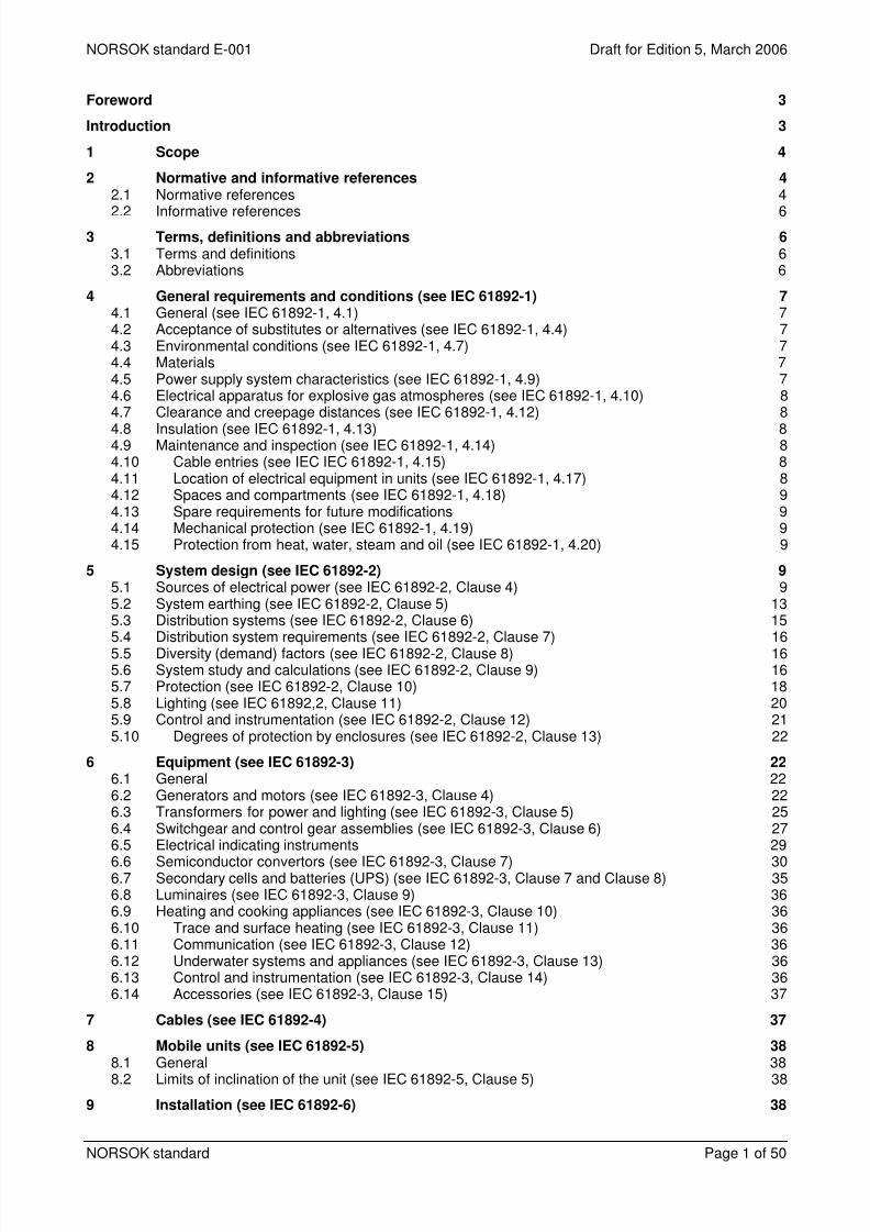
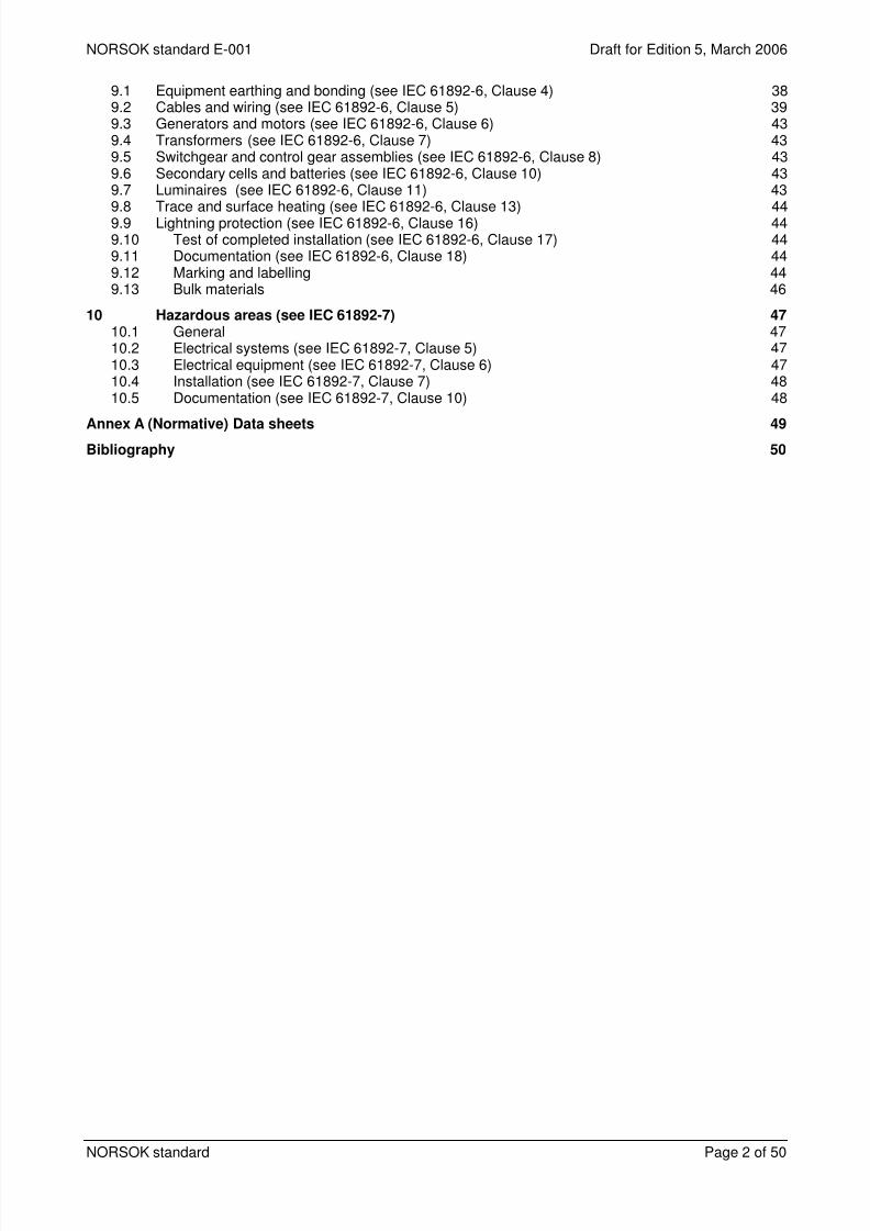
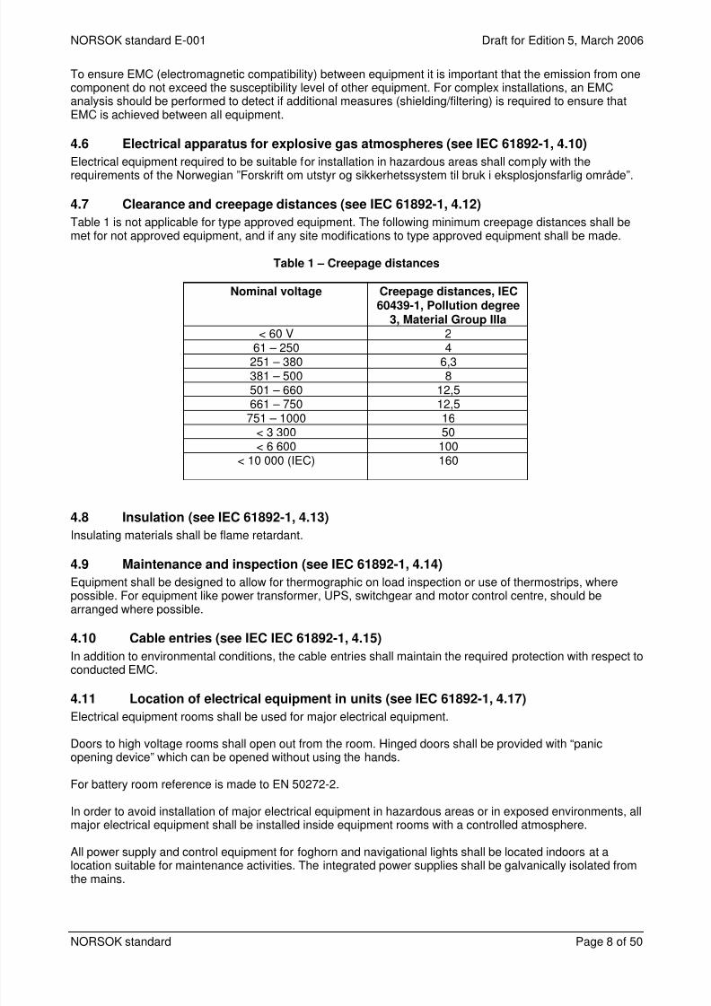
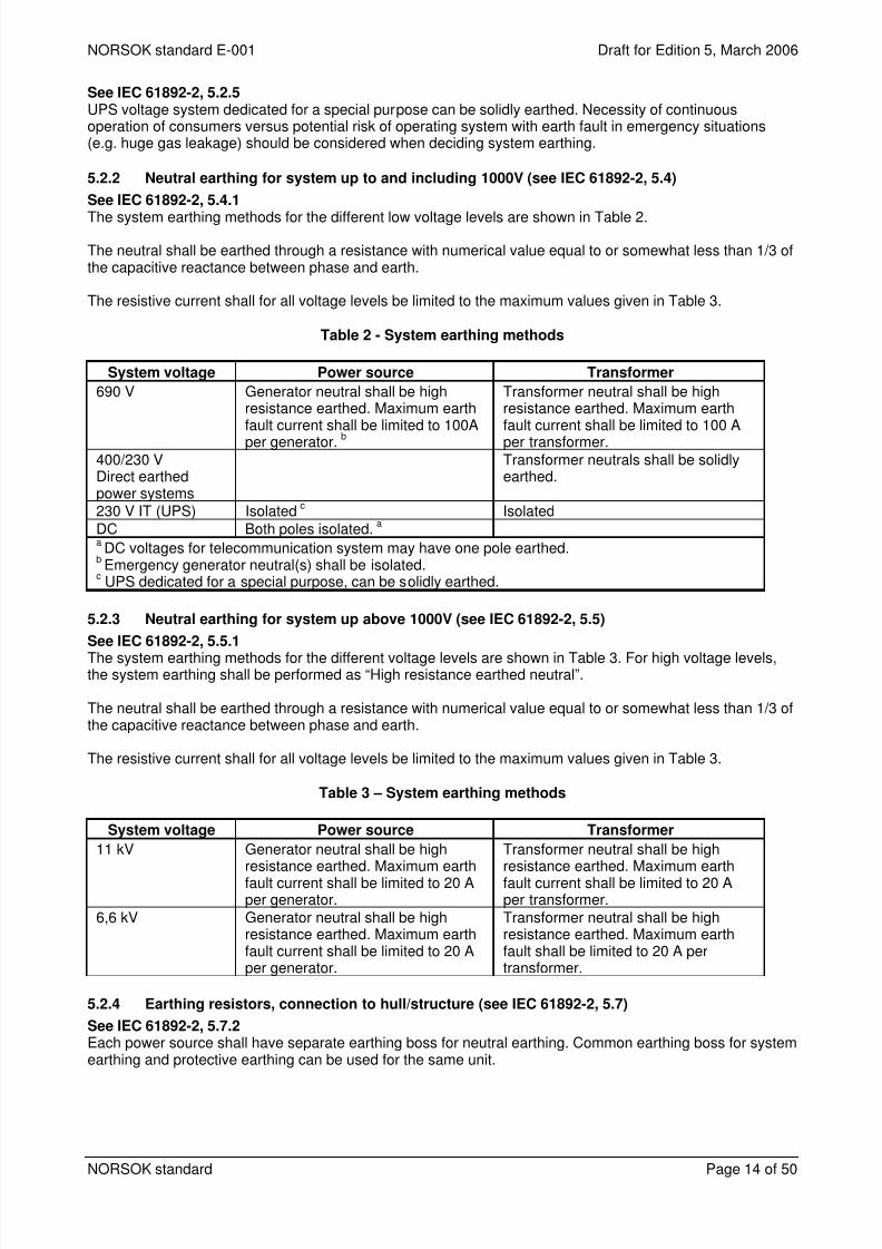
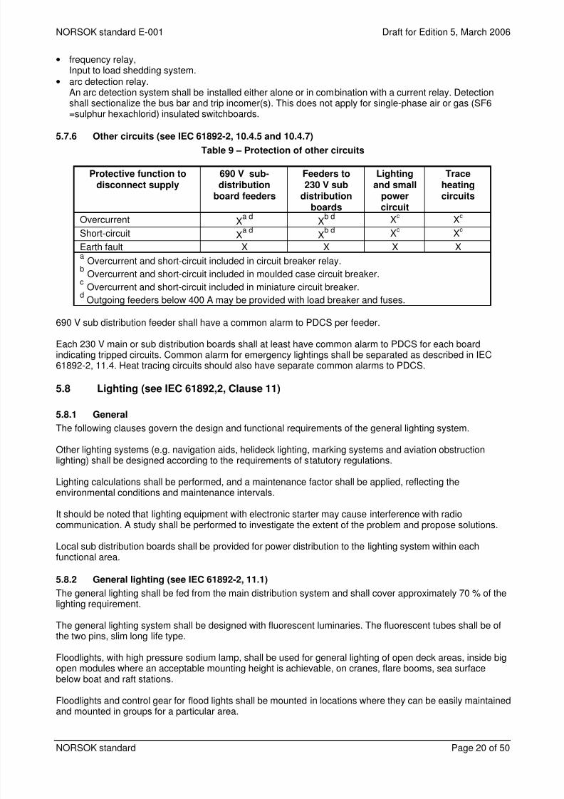

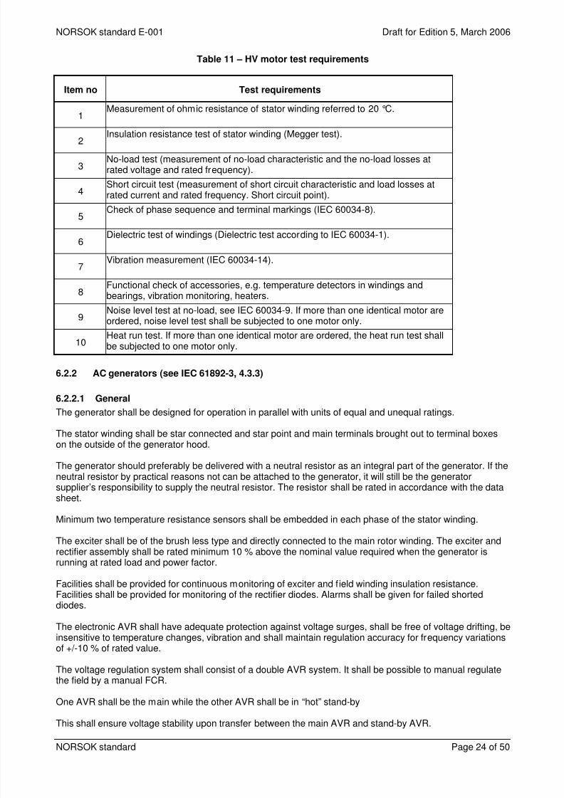
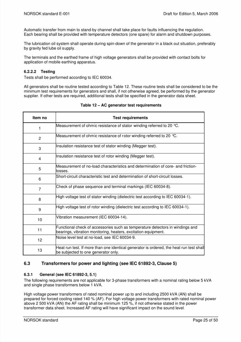
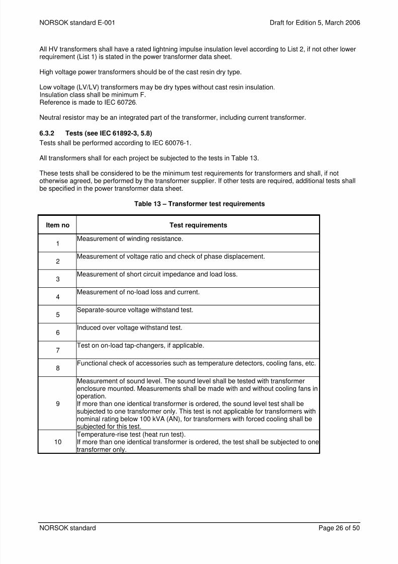
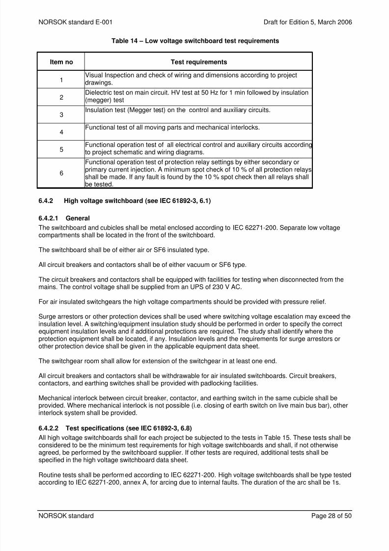
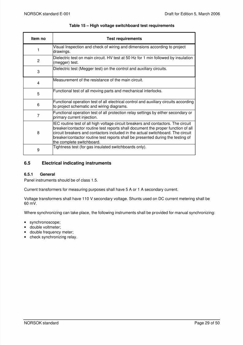
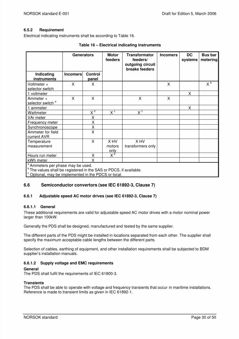
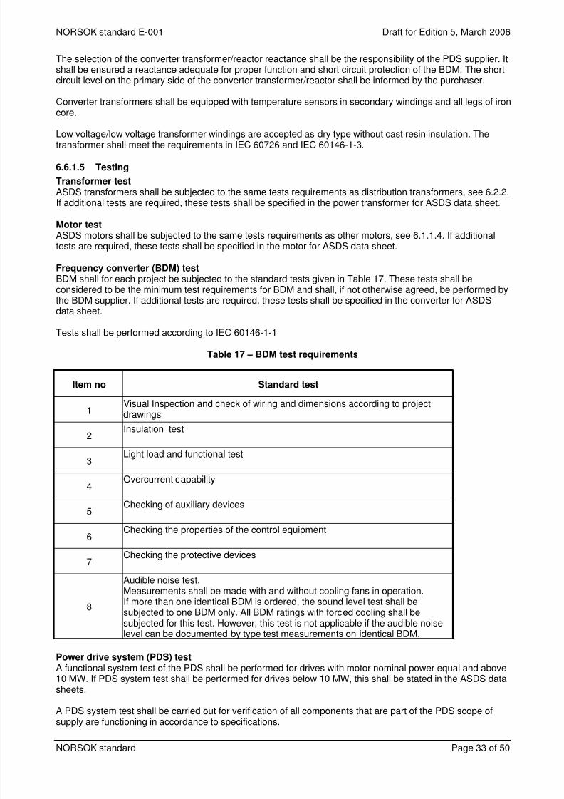
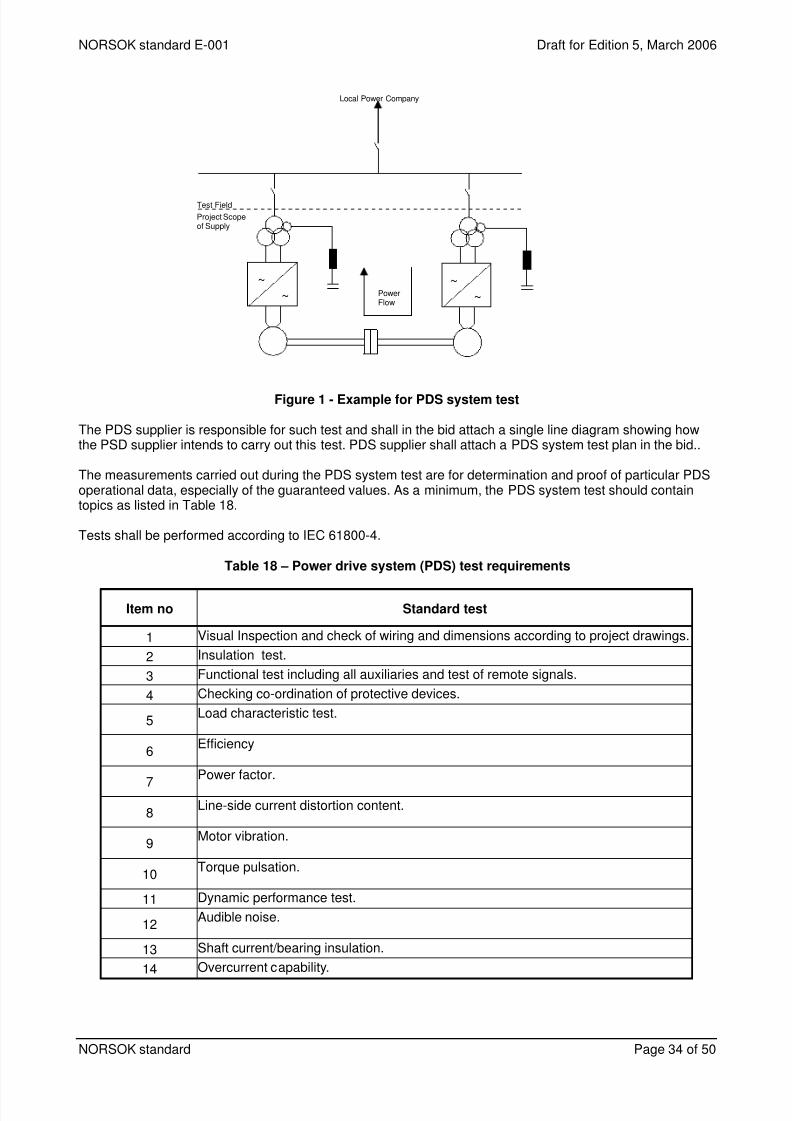
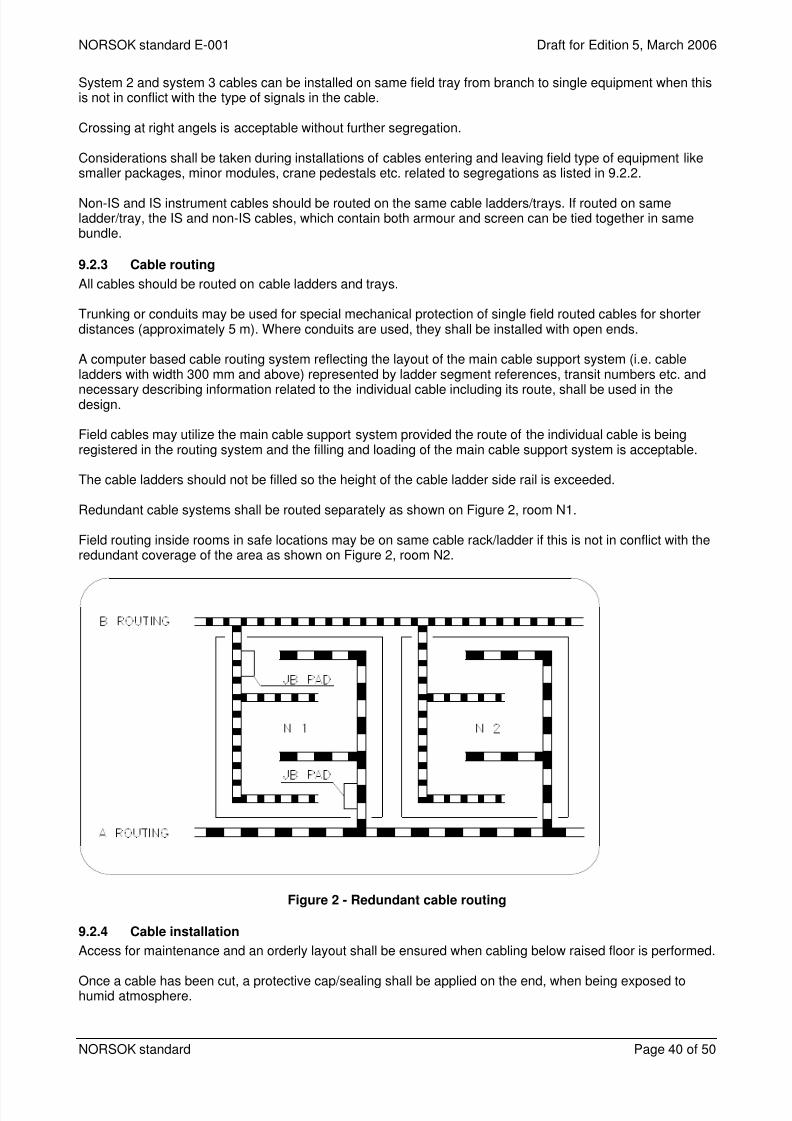


![ffiTtrTr*I - dolrm.gov.npdolrm.gov.np/uploadphotos/2/Minimum Land Value... · ft € 'E {E ] [E fi' E{E; E E {*,? € s ; E E & E E e € fr* E >{E $- E >-E ?: )"- F E & E p.2. E](https://static.documents.pub/doc/80x56/5d33056588c993d91a8c1267/ffittrtri-dolrmgov-land-value-ft-e-e-e-fi-ee-e-e-.jpg)


