30
E E 681 - Module 13 © Wayne D. Grover 2002, 2003 1 p-Cycles Jens Myrup Pedersen Aalborg University © Wayne D. Grover 2002, 2003 E E 681 - Module 13 ( Version for book website Dec. 2003)
| Date post: | 21-Dec-2015 |
| Category: |
Documents |
| View: | 213 times |
| Download: | 0 times |

E E 681 - Module 13 © Wayne D. Grover 2002, 2003 1
p-Cycles
Jens Myrup PedersenAalborg University
© Wayne D. Grover 2002, 2003
E E 681 - Module 13
( Version for book website Dec. 2003)

E E 681 - Module 13 © Wayne D. Grover 2002, 2003 2
Background and Motivation
“ Ring “A. 50 msec restoration timesB. Complex network planning
and growthC. High installed capacity for
demand-servedD. Simple, low-cost ADMsE. Hard to accommodate
multiple service classes F. Ring-constrained routing
“Mesh”G. Up to 1.5 sec restoration
timesH. Simple, exact capacity
planning solutions
I. well under 100% redundancy
J. Relatively expensive DCS/OXCK. Easy / efficient to design for
multiple service classesL. Shortest-path routing
“ Shopping list” : A, D, H, I, L (and K) please...keep
the rest

E E 681 - Module 13 © Wayne D. Grover 2002, 2003 3
Relative Characteristics of Known Schemes
Restoration Times
Capacity Redundancy
1+1 APS, Rings
p-CyclesMesh Span Restoration
Shared Backup Path Protection (SBPP)
True Mesh Path Restoration
100% redundancy: “the dividing line”
E E 681 - Module 13 © Wayne D. Grover 2002, 2003 4
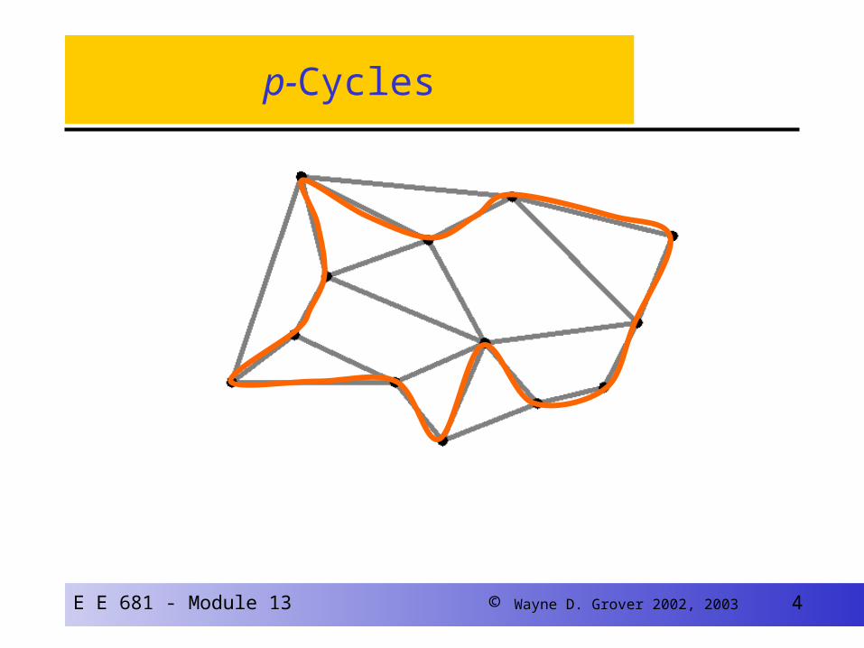
p-Cycles
E E 681 - Module 13 © Wayne D. Grover 2002, 2003 5
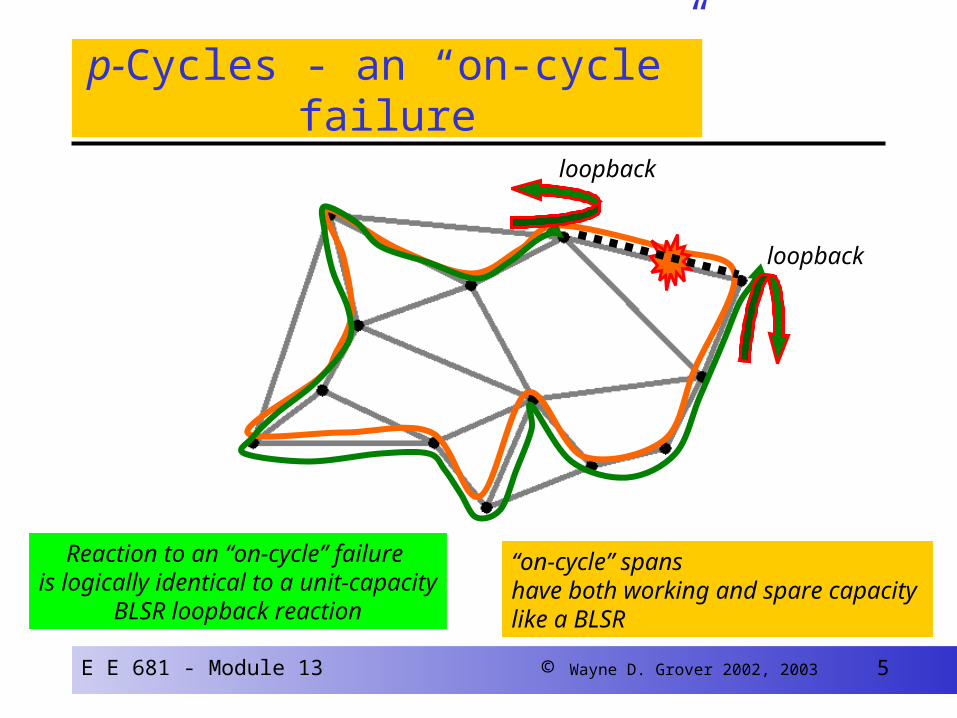
p-Cycles - an “on-cycle” failure
Reaction to an “on-cycle” failure is logically identical to a unit-capacity
BLSR loopback reaction
loopback
loopback
“on-cycle” spans have both working and spare capacity like a BLSR

E E 681 - Module 13 © Wayne D. Grover 2002, 2003 6
p-Cycles - a “straddling span” failure
Reaction to a straddling span failure is to switch failed signals onto two protection pathsformed from the related p-cycle
Break-in
Break-in
Straddling spans have two protected working signal units and haveno spare capacity

E E 681 - Module 13 © Wayne D. Grover 2002, 2003 7
A lot !
Re-consider the example:
It consumes 13 unit-hops of spare capacity
It protects one working signal on 13 spans and two working on 9 spans
i.e., spare / working ratio = 13 / (13*1 + 9*2 )
= 42%
How much difference can this make ?
A fully-loaded Hamiltonian p-cycle reaches the redundancy limit, 1/(d-1)
x2x2
x2 x2
x2
x2
x2
x2
x2
E E 681 - Module 13 © Wayne D. Grover 2002, 2003 8
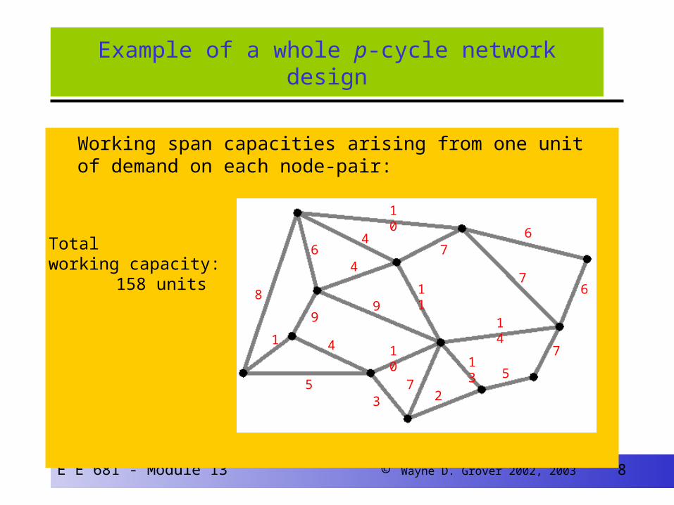
Working span capacities arising from one unit of demand on each node-pair:
Example of a whole p-cycle network design
Total working capacity:
158 units8
1
5
6
9
4
9
4
4
10
73 2
13
11
10
7
6
14
5
7
6
7
E E 681 - Module 13 © Wayne D. Grover 2002, 2003 9
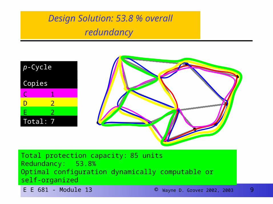
Design Solution: 53.8 % overall redundancy
A 1B 1C 1D 2E 2
Total protection capacity: 85 unitsRedundancy: 53.8%Optimal configuration dynamically computable or self-organized
p-Cycle Copies
Total: 7
E E 681 - Module 13 © Wayne D. Grover 2002, 2003 10
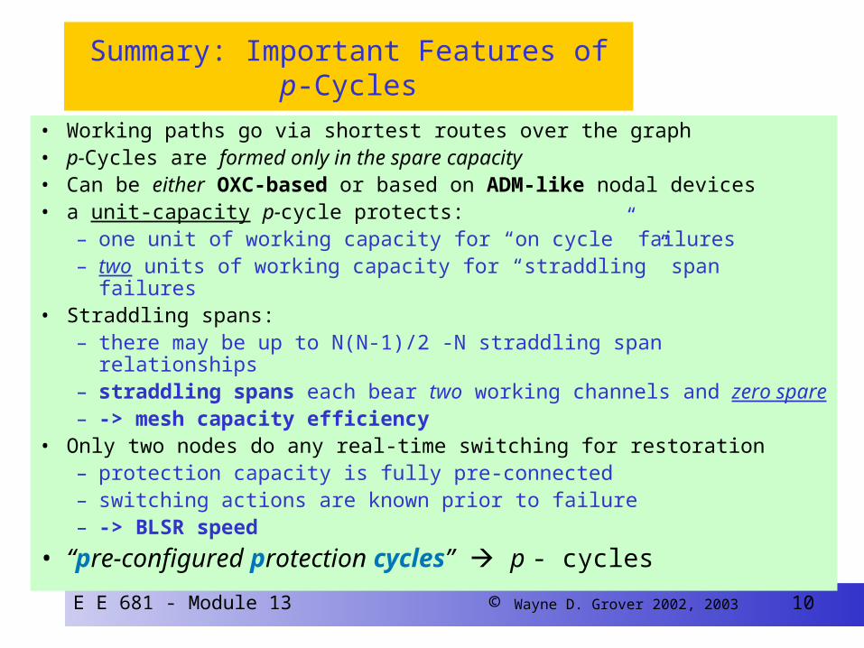
Summary: Important Features of p-Cycles
• Working paths go via shortest routes over the graph• p-Cycles are formed only in the spare capacity• Can be either OXC-based or based on ADM-like nodal devices• a unit-capacity p-cycle protects:
– one unit of working capacity for “on cycle” failures– two units of working capacity for “straddling” span failures
• Straddling spans:– there may be up to N(N-1)/2 -N straddling span relationships– straddling spans each bear two working channels and zero spare– -> mesh capacity efficiency
• Only two nodes do any real-time switching for restoration – protection capacity is fully pre-connected– switching actions are known prior to failure– -> BLSR speed
• “pre-configured protection cycles” p - cycles
E E 681 - Module 13 © Wayne D. Grover 2002, 2003 11
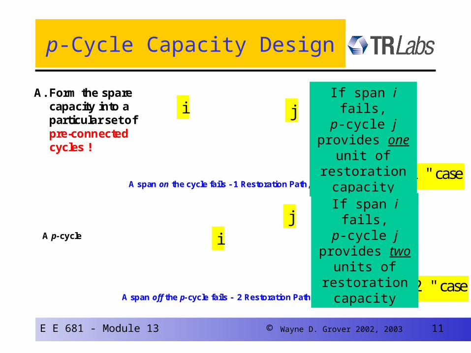
p-Cycle Capacity Design
A p-cycle
A span on the cycle fails - 1 Restoration Path, BLSR-like
A span off the p-cycle fails - 2 Restoration Paths, Mesh-like
A. Form the spare capacity into a particular set of pre-connected cycles !
," 1 " case
i jx
," 2 " case
i jx
If span i fails,p-cycle j provides
one unit of restoration capacity
If span i fails,p-cycle j provides
two units of restoration capacity
i j
i
j
E E 681 - Module 13 © Wayne D. Grover 2002, 2003 16
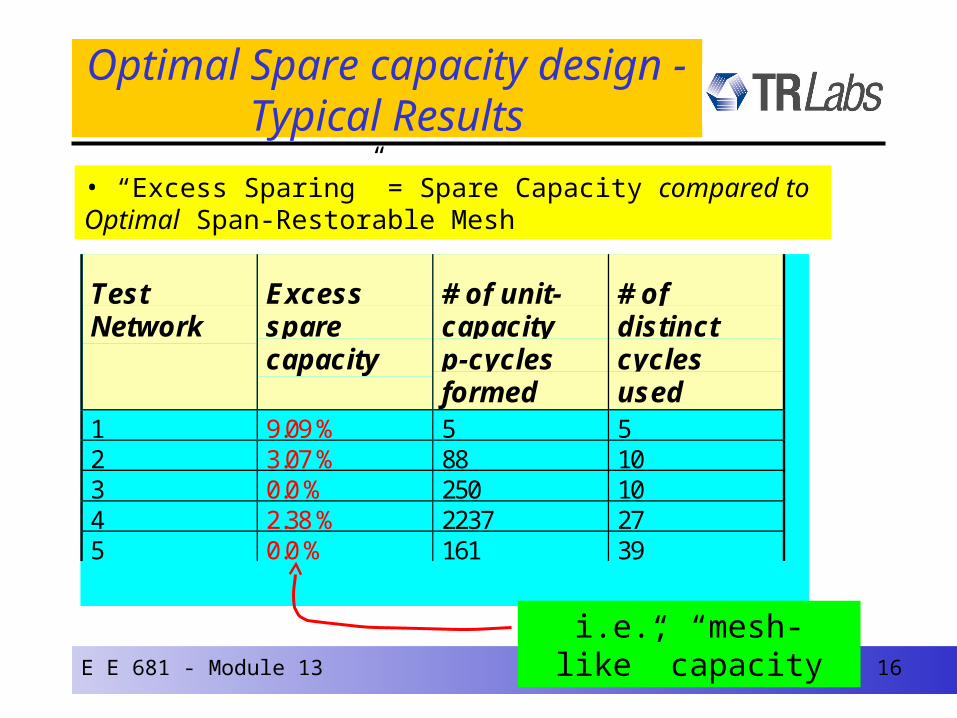
Optimal Spare capacity design - Typical Results
TestNetwork
Excesssparecapacity
# of unit-capacityp-cyclesformed
# ofdistinctcyclesused
1 9.09 % 5 52 3.07 % 88 103 0.0 % 250 104 2.38 % 2237 275 0.0 % 161 39
• “Excess Sparing” = Spare Capacity compared to Optimal Span-Restorable Mesh
i.e., “mesh-like” capacity

E E 681 - Module 13 © Wayne D. Grover 2002, 2003 17
Understanding why p-cycles are so efficient...
9 Spares cover 9 Workers
9 Spares
cover 29 working channels
on 19 spans
Spare
Working Coverage
UPSR or
BLSR
p-Cycle…with same
spare capacity
“the clam-shell diagram”
E E 681 - Module 13 © Wayne D. Grover 2002, 2003 18
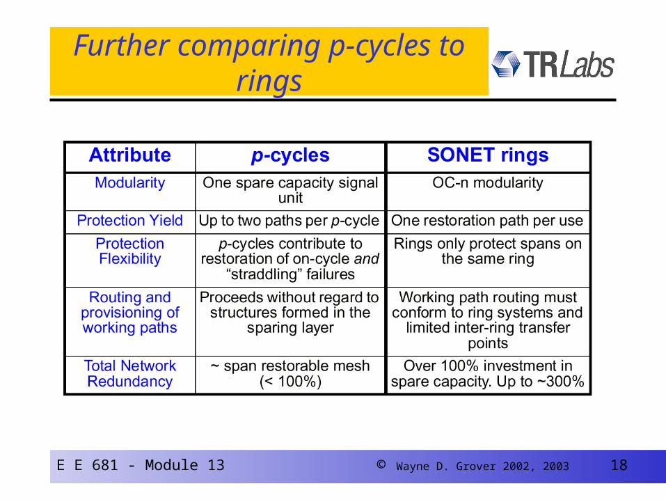
Further comparing p-cycles to rings

E E 681 - Module 13 © Wayne D. Grover 2002, 2003 19
A Priori p-Cycle Efficiency: AE(p)
• AE (p) measures a cycle’s potential to provide protection relationships for working channels
,
,, ,
,1
2
p i
p iS p C pi S
i C pi S X
X S SAE p
c S
Xp,i = 1 if on cycleXp,i = 2 if straddler
SS,p = 3
SC,p = 9
AE(p) = 1.67
SS,p = 4
SC,p = 10
AE(p) = 1.80
SC,p = # on cycleSS,p = # straddlersci = unit cost of i
E E 681 - Module 13 © Wayne D. Grover 2002, 2003 20
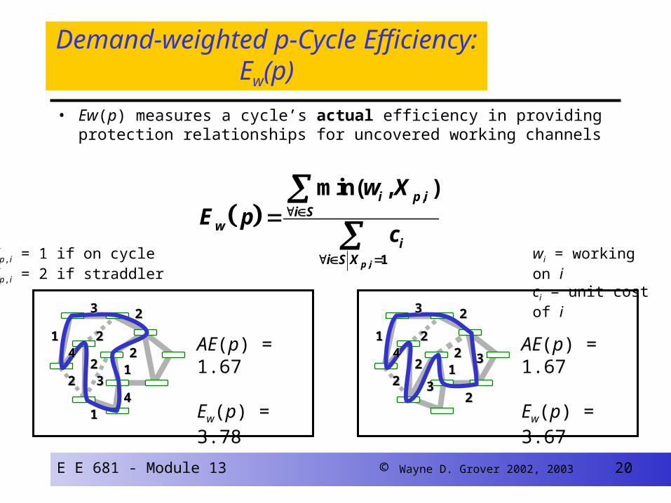
Demand-weighted p-Cycle Efficiency: Ew(p)
• Ew(p) measures a cycle’s actual efficiency in providing protection relationships for uncovered working channels
,
,
1
min( , )
p i
i p ii S
wi
i S X
w XE p
c
11
33
22
3322
1144
1122
22
2244
AE(p) = 1.67
Ew(p) = 3.78
11
33
22
3322
33
22
1122
22
2244
AE(p) = 1.67
Ew(p) = 3.67
Xp,i = 1 if on cycleXp,i = 2 if straddler
wi = working on ici = unit cost of i

E E 681 - Module 13 © Wayne D. Grover 2002, 2003 21
Self-organization of the p-cycles ...
• p-cycles certainly could be centrally computed and configured. – based on the preceding formulation
However, an interesting option is to consider if the network can adaptively and continually self-organize - a near-optimal set of p-cycles within itself, - for whatever demand pattern and capacity
configuration it currently finds.
E E 681 - Module 13 © Wayne D. Grover 2002, 2003 22
Self-organization of the p-cycles
• Based on an extension / adaptation of SHN™ distributed mesh restoration algorithm– “DCPC” = distributed cycle pre-configuration protocol
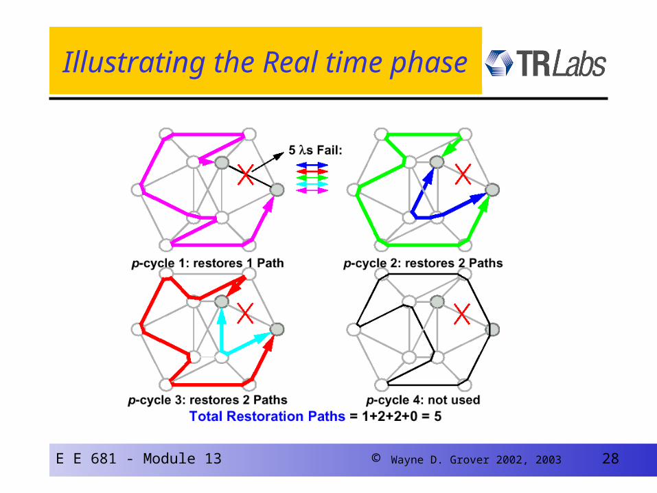
• Operates continually in background– Non-real time phase self-organizes p-cycles
– Real time phase is essentially BLSR switching
– p-cycles in continual self-test while in “storage”
• Centralized “oversight” but not low-level control– Method is autonomous, adaptive
• Networks actual state on the ground is the database
E E 681 - Module 13 © Wayne D. Grover 2002, 2003 23
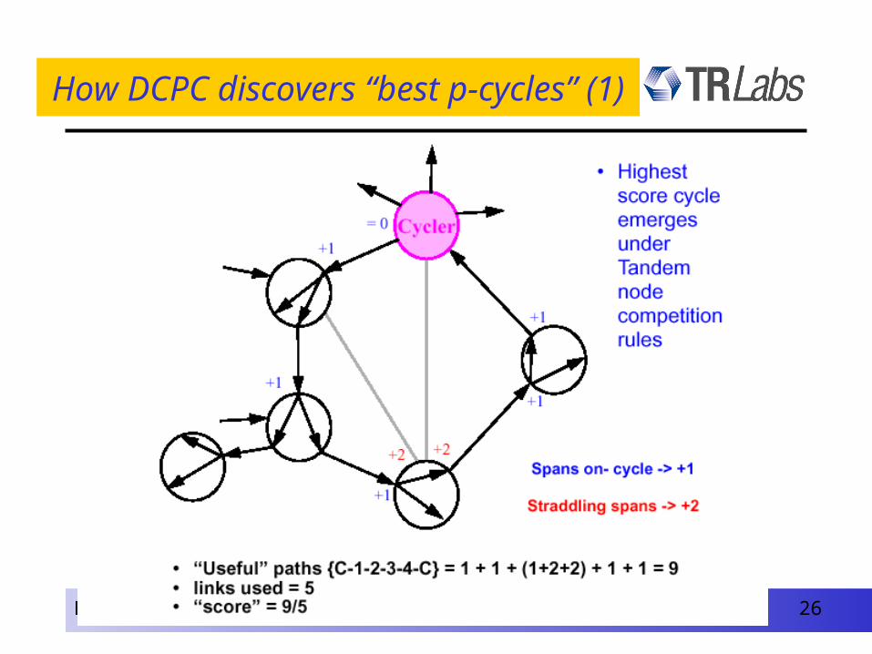
Key concepts of DCPC protocol
• Node roles:– Cycler node state , Tandem node state
• DCPC implemented as event-driven Finite State Machine
(FSM)
• Nodal interactions are (directly) only between adjacent nodes– Indirectly between all nodes (organic self-organization)– via “statelets” on carrier / optical signal overheads
• Three main steps / time-scales / processes– Each nodes act individually, “exploring” network from its standpoint as
cycler node.– All nodes indirectly compare results – Globally best p-cycle is created
E E 681 - Module 13 © Wayne D. Grover 2002, 2003 24
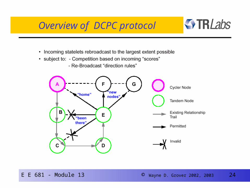
Overview of DCPC protocol

E E 681 - Module 13 © Wayne D. Grover 2002, 2003 25
How DCPC discovers “best p-cycles” (2)
E E 681 - Module 13 © Wayne D. Grover 2002, 2003 26
How DCPC discovers “best p-cycles” (1)
E E 681 - Module 13 © Wayne D. Grover 2002, 2003 27
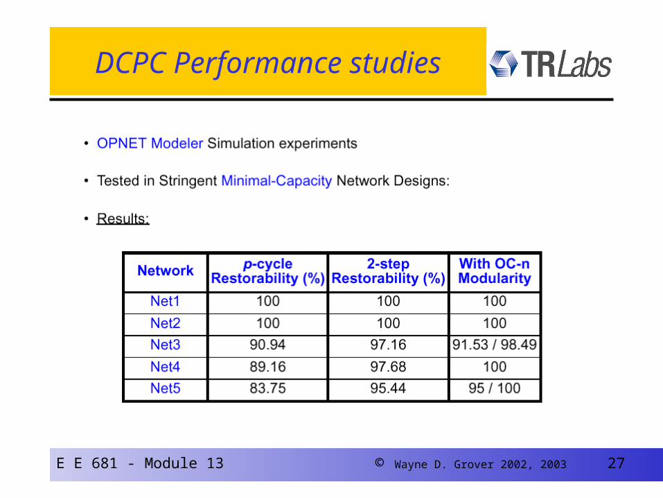
DCPC Performance studies
E E 681 - Module 13 © Wayne D. Grover 2002, 2003 28
Illustrating the Real time phase

E E 681 - Module 13 © Wayne D. Grover 2002, 2003 29
Adapting p-cycles to the IP-layer …

E E 681 - Module 13 © Wayne D. Grover 2002, 2003 30
IP Network Restoration
• IP Networks are already “Restorable”• Restoration occurs when the Routing protocol updates
the Routing Tables• This update can take a Minute or more - Packets are lost
until this happens
• Speed-up of IP Restoration is needed• Not losing packets would be great too• Also some control over capacity / congestion impacts
needed
• p-cycles proposed as “fast” part of a fast + slow strategy that retains normal OSPF-type routing table re-convergence
E E 681 - Module 13 © Wayne D. Grover 2002, 2003 38
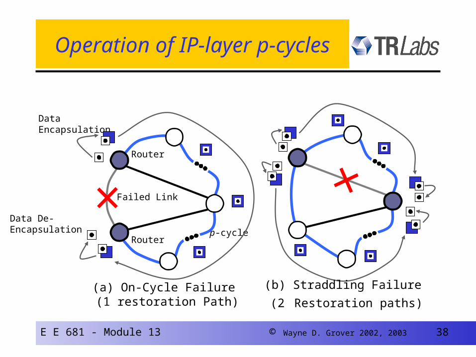
Operation of IP-layer p-cycles
Failed Link
Router
Data De-Encapsulation
Data Encapsulation
Router
p-cycle
(a) On-Cycle Failure (1 restoration Path)
(b) Straddling Failure
(2 Restoration paths)

E E 681 - Module 13 © Wayne D. Grover 2002, 2003 43
• Node Encircling p-Cycles. Each Node has a p-Cycle dedicated to its failure
• For each Node, a p-Cycle is chosen which includes all logically “Adjacent” Nodes but not the Protected Node
Router Failure Restoration using“Node-Encircling” p-Cycles
Node-Encircling p-
cycle
Other Nodes
Encircled Node

E E 681 - Module 13 © Wayne D. Grover 2002, 2003 44
p-Cycles are Virtual Circuits/Protection Structures which can redirect Packets around Failures– Plain IP is Connectionless but p-Cycles can be realized with
MPLS, IP Tunneling/Static Routes
Router Restoration using“Node-Encircling” p-Cycles
Node Failure

E E 681 - Module 13 © Wayne D. Grover 2002, 2003 49
Concluding Comments
• p-cycles offer new approaches to both WDM and IP-layer transport
– “ mesh-like efficiency with ring-like speed ”
• Capacity-planning theory
– for 100% span restoration in WDM / Sonet with mesh sparing
– for controlled worst-case over-subscription in IP-layer
• “Node-encircling” p-cycles
– fast integrated restoration against either router or link-failures
• Nortel has implemented span-restoration via IP p-cycles
– ~ 10 msec restoration time, no packet loss in their experiments
• Ongoing studies:
• Integrated planning of composite node / link restoration p-cycles
• Availability analysis of p-cycles


