Effects of atmospheric temperature on corona generated ionic currents of HVDC Transmission lines M. Prameela 1 , K. Vijaya Bhaskar Reddy 2 , N. Bhoopal 3 1 Professor, 2 Professor, 3 Professor & Head, Dept of EEE, B.V.Raju Institution of Technology, Narsapur Medak(Dist),Telangana, India. [email protected], [email protected], [email protected]April 28, 2018 Abstract HVDC transmission is more suitable for a long distance bulk amount of power transmission. In HVDC Transmission system corona is the major problem, due to generation of ions on the positive and negative polarity of the conductor. Thus the ions of the same polarity of the conductor drifts in the inter electrode region results in flow of ionic current be- tween the conductor to ground plane. The factors influenc- ing ionic current are temperature, pressure, humidity, con- ductor size, conductor height, etc. They have a significant influence on the enhancement of ionic current flow at ground levels. Designing of HVDC transmission lines at UHV levels in hot weather conditions prevailing in a country like India needs more attention. This paper presents the results of the laboratory study on effects of atmospheric temperatures on the corona generated ionic currents in HVDC transmission 1 International Journal of Pure and Applied Mathematics Volume 118 No. 24 2018 ISSN: 1314-3395 (on-line version) url: http://www.acadpubl.eu/hub/ Special Issue http://www.acadpubl.eu/hub/
Transcript
Effects of atmospheric temperature oncorona generated ionic currents of
HVDC Transmission lines
M. Prameela1, K. Vijaya Bhaskar Reddy2,N. Bhoopal3
1Professor, 2Professor, 3Professor & Head,Dept of EEE, B.V.Raju Institution of Technology,
HVDC transmission is more suitable for a long distancebulk amount of power transmission. In HVDC Transmissionsystem corona is the major problem, due to generation ofions on the positive and negative polarity of the conductor.Thus the ions of the same polarity of the conductor drifts inthe inter electrode region results in flow of ionic current be-tween the conductor to ground plane. The factors influenc-ing ionic current are temperature, pressure, humidity, con-ductor size, conductor height, etc. They have a significantinfluence on the enhancement of ionic current flow at groundlevels. Designing of HVDC transmission lines at UHV levelsin hot weather conditions prevailing in a country like Indianeeds more attention. This paper presents the results of thelaboratory study on effects of atmospheric temperatures onthe corona generated ionic currents in HVDC transmission
1
International Journal of Pure and Applied MathematicsVolume 118 No. 24 2018ISSN: 1314-3395 (on-line version)url: http://www.acadpubl.eu/hub/Special Issue http://www.acadpubl.eu/hub/
lines at ground levels for different experimental configura-tions.
The HVDC transmission lines are extensively used for bulk amountof power transmission. Compared to HVAC transmission systemHVDC transmission is inexpensive with moderate electrical losses[1]. To design the HVDC Transmission lines at UHV levels, variousproblems associated with it are being studied extensively elsewherein the world. One of the major problems in designing of a HVDCline is their corona phenomenon which leads to corona discharge [2].In a corona discharging situation, both positive and negative ionsare generated in the vicinity of line. The primary effect of coronadischarge on a DC transmission line is variation of ionic currentflow at ground levels. It also accounts for, additional adverse ef-fects of corona power loss, audible noises, and radio Interface etc.With the existence of any living organism under and near the trans-mission line causes physiological effects due to dissimilarity of ioniccurrent flow at ground level [3][4]. So, it is vital examining theUHVDC transmission lines at different weather conditions over ayear before design the practical transmission lines. Now, in IndiaHVDC overhead lines operating up to 500 kV are in operation andlines of higher voltages are under consideration to meet the powerdemand. The construction of a 800 kV with the power transfercapability of 6000 MW is under progress. This authenticates therequirement of enormous study of variation of ionic current flowat different atmospheric temperatures before designing the HVDCtransmission lines at UHV levels. To overcome this problem scaledown models of experimental findings at actual atmosphere, thatis, under outdoor conditions can provide significant support to eval-uate the effect of atmospheric conditions on ionic current flow atground levels under the transmission lines. This paper presents thelaboratory scale down experimental studies carried out at outdoorconditions.
2
International Journal of Pure and Applied Mathematics Special Issue
2 IONIC CURRENT MEASURMENT
At voltages above corona inception, the breakdown of air resultsin space charge around the conductors. Some ions found in thisregion migrate to earth and in effect reduce the resistance of thefree space. As a result, the gradient at the conductor surface isdecreased, where as the gradient at the ground plane is increased.The drifting of space charge towards the ground plane or towardsthe conductor of opposite polarity gives rise to a current flow in theentire inter electrode space between the conductors and the groundplane [10]. To investigate ionic current density on the ground, acollecting plate called Wilson plate is used to capture ions whichdrift towards the ground. The ionic current is measured by thedigital DC nano ammeter.
Fig.1. Schematic diagram of ionic current measurement system
3 WILSON PLATE
Measurement of the ionic current under the HVDC transmissionlines are carried out using a plain collecting plate and a DC nanoammeter combination. Schematic view of the measurement of ioniccurrent density of HVDC transmission line is shown in Fig.1.Wilsonplate of size 1x1 m2 was used in this study.
The digital DC nano ammeter reads the current from sensingelectrode directly under the line conductor. The plain plate, usu-ally referred as Wilson plate[10], placed on the ground under thetransmission line is shown in Fig.2.
3
International Journal of Pure and Applied Mathematics Special Issue
Fig.2. Schematic diagram of Wilson plate
4 EXPERIMENTAL RESULTS
Measurement of Ionic current under different ambient temperaturesCase: A The set-up used for measurement ionic current from a cop-per conductor of size 1.2 mm is shown in Fig.3. The conductor issupported at end using two post insulators. The source connectionto the conductor was made using capsules of 70 mm diameter toavoid corona from the connection. The height of the copper con-ductor was 1.3 m above the ground. Wilson plate is placed at thecenter between the two post insulators, under the conductor. Theconductor was energized with positive polarity of DC voltage. Theionic current was measured with voltage increasing from 30 kV to140 kV. The ionic current was measured at two different ambientconditions i.e. at 41C and 32C. The measured ionic current underthe conductor at different atmospheric temperatures is shown inTable I.
4
International Journal of Pure and Applied Mathematics Special Issue
Fig.3. Experimental test setup
TABLE 1. Magnitude of ionic current under different ambienttemperatures
It can be seen that the magnitude of the ionic current is more at41C than at 32C for all the test voltages. The variation of positiveionic current with temperature is shown in Fig.4.
5
International Journal of Pure and Applied Mathematics Special Issue
Fig.4. Variation of positive Ionic Current with temperature
Case: BFor the same conductor configuration in case A, The conductor
was energized with negative polarity of the DC voltage from 30 kVto 140 kV. The measured negative ionic current under the conductorat different atmospheric temperatures is shown in table II.
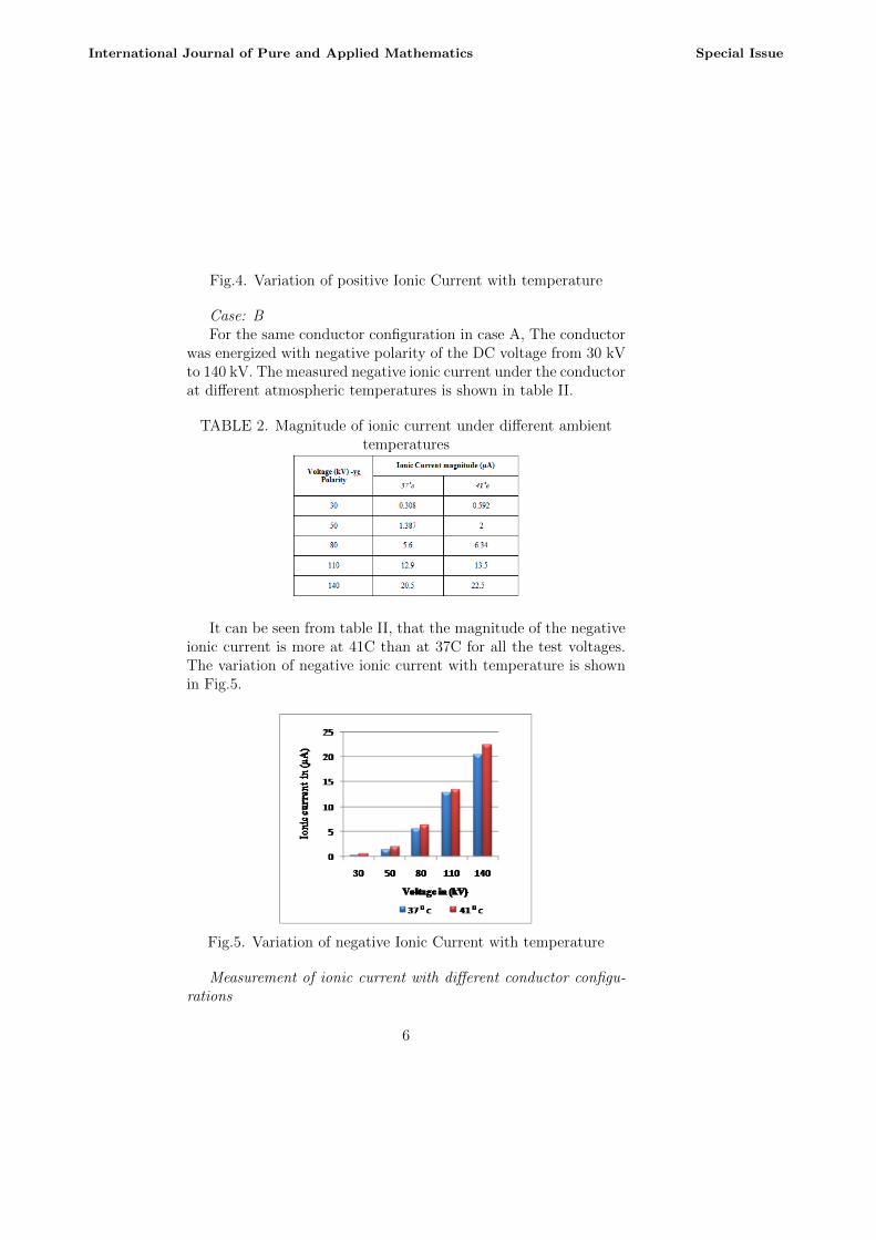
TABLE 2. Magnitude of ionic current under different ambienttemperatures
It can be seen from table II, that the magnitude of the negativeionic current is more at 41C than at 37C for all the test voltages.The variation of negative ionic current with temperature is shownin Fig.5.
Fig.5. Variation of negative Ionic Current with temperature
Measurement of ionic current with different conductor configu-rations
6
International Journal of Pure and Applied Mathematics Special Issue
The ionic current is measured with different conductor configu-rations at the same height. Ionic current from copper conductorsof sizes 0.6 mm and 1.2 mm. were measured. Here height betweenconductor and ground plate is 1.3 m. Wilson plate is placed atthe center between the two post insulators, under the conductor.The conductor was energized with negative polarity of the DC volt-age from 30 kV to 110 kV. The measured ionic current under theconductor of two different sizes is shown in table III.
TABLE 3. Magnitude of ionic current from conductor of differentdiameters
The variation of ionic current with negative voltage for conduc-tor of two different diameters is shown in Fig.6. The ionic currentfrom 0.6 mm diameter conductor is more than from 1.2 mm diam-eter conductor.
Fig.6. Variation of ionic current with different conductor sizes
Measurement of ionic current from conductor with different heightsCase: A
The ionic current density is also measured at two different con-ductor height configurations 1.7 m and 1.2 m. The diameter of
7
International Journal of Pure and Applied Mathematics Special Issue
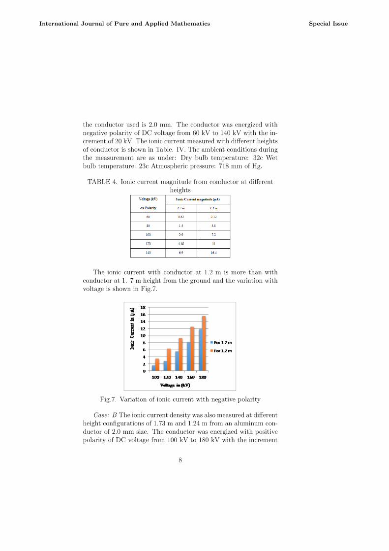
the conductor used is 2.0 mm. The conductor was energized withnegative polarity of DC voltage from 60 kV to 140 kV with the in-crement of 20 kV. The ionic current measured with different heightsof conductor is shown in Table. IV. The ambient conditions duringthe measurement are as under: Dry bulb temperature: 32c Wetbulb temperature: 23c Atmospheric pressure: 718 mm of Hg.
TABLE 4. Ionic current magnitude from conductor at differentheights
The ionic current with conductor at 1.2 m is more than withconductor at 1. 7 m height from the ground and the variation withvoltage is shown in Fig.7.
Fig.7. Variation of ionic current with negative polarity
Case: B The ionic current density was also measured at differentheight configurations of 1.73 m and 1.24 m from an aluminum con-ductor of 2.0 mm size. The conductor was energized with positivepolarity of DC voltage from 100 kV to 180 kV with the increment
8
International Journal of Pure and Applied Mathematics Special Issue
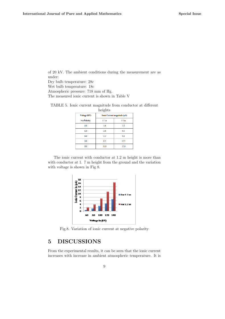
of 20 kV. The ambient conditions during the measurement are asunder:Dry bulb temperature: 28cWet bulb temperature: 18cAtmospheric pressure: 718 mm of Hg.The measured ionic current is shown in Table V
TABLE 5. Ionic current magnitude from conductor at differentheights
The ionic current with conductor at 1.2 m height is more thanwith conductor at 1. 7 m height from the ground and the variationwith voltage is shown in Fig 8.
Fig.8. Variation of ionic current at negative polarity
5 DISCUSSIONS
From the experimental results, it can be seen that the ionic currentincreases with increase in ambient atmospheric temperature. It is
9
International Journal of Pure and Applied Mathematics Special Issue
also observed that, the magnitude of ionic current depends on thesize of the conductor. As the size of the conductor is large, themagnitude of ionic current will be less irrespective of polarity.
The measured ionic current at ground levels is more for conduc-tor energized with negative polarity DC as compared to positivepolarity DC voltage in all cases.
According to the experimental result, the magnitude of ioniccurrent varies with the height of the conductor. As the height of theconductor increases, the magnitude of ionic current is reduced andvice versa. It is observed that ionic current flow of a HVDC line atactual field conditions has huge variations in magnitude, dependson atmospheric conditions. This indicates that the atmosphericparameters such as temperature, pressure, wind velocity, humidity,etc., have the significant influence in the generation of ions in thevicinity of the HVDC transmission lines.
6 Conclusion
The experimental investigation on different HVDC line conduc-tors by various experimental setups at outdoor conductor was con-ducted. From this deliberation, it is achieved that the ionic currentis proportional to atmospheric temperature.1. The ionic current varies inversely with diameter of the conduc-tor.2. The ionic current varies inversely with height of the conductor
7 ACKNOWLEDGMENT
The authors thank management, officers and technicians of CPRIfor giving permission to conduct experiments and giving permissionto publish this paper.
References
[1] Zhaonan Luo, Calculation of the 3-D Ionized Field Un-der HVDC Transmission Lines IEEE TRANSACTIONS ON
10
International Journal of Pure and Applied Mathematics Special Issue
MAGNETICS, VOL. 47, NO. 5, MAY 2011.
[2] P.Sarma Maruvada, Influence of Ambient Electric Fieldonthe Corona Performance of HVDC transmission liines, IEEETRANSACTIONS ON POWER DELIVERY, VOL. 29, NO.2, APRIL 2014.
[3] P.Sarma Maruvada, Electric Field and Ion Current Envi-ronment of HVdc Transmission Lines: Comparison Of Cal-culations and Measurements, IEEE TRANSACTIONS ONPOWER DELIVERY, VOL. 27, NO. 1, JANUARY 2012.
[4] Yongzan Zhen, Xiang Cui, Senior Member, IEEE, TiebingLu, Xuebao Li, Chao Fang, and Xiangxian Zhou, 3-D Finite-Element Method for Calculating the Ionized Electric Fieldand the Ion Current of the Human Body Model Under theUHVDC Lines IEEE TRANSACTIONS ON POWER DELIV-ERY, VOL. 28, NO. 2, APRIL 2013.
[5] Yongzan Zhen, Xiang Cui, Tiebing Lu, Xiangxian Zhou, andZhaonan Luo, High Efficiency FEM Calculation of the Ion-ized Field Under HVDCTransmission LinesIEEE TRANSAC-TIONS ON MAGNETICS, VOL. 48, NO. 2, FEBRUARY2012.
[6] Jie Liu, Jun Zou, Jihuan Tian, and Jiansheng Yuan, Analysisof Electric Field, Ion Flow Density, and Corona Loss of Same-Tower Double-Circuit HVDC Lines Using Improved FEMIEEE TRANSACTIONS ON POWER DELIVERY, VOL. 24,NO. 1, JANUARY 2009
[7] Zhaonan Luo , Xiang Cui , Jiayu Lu Analysis of IonizedField under HVDC Transmission Lines with Buildings Nearby2010 Asia-Pacific International Symposium on Electromag-netic Compatibility, April 12 - 16, 2010, Beijing, China.
[8] Bo Zhang, Member, IEEE, Han Yin, Jinliang He, Computa-tion of Ion-Flow Field Near the Metal Board House Under theHVDC Bipolar Transmission Line IEEE TRANSACTIONSON POWER DELIVERY, VOL. 28, NO. 2, APRIL 2013.
11
International Journal of Pure and Applied Mathematics Special Issue
[9] N.M. Ijumba , M.J. Lekganyane , COMPARATIVE STUD-IES OF AC AND DC CORONA POWER LOSSES IN ANINDOOR CORONA CAGE Proceedings of the 16th Interna-tional Symposium on High Voltage Engineering 2009 SAIEE,Innes House, Johannesburg.
[10] Chao Fang, Xiang Cui, Senior Member, IEEE, XiangxianZhou, Student Member, IEEE, Tiebing Lu, Impact Fac-tors in Measurements of Ion-Current Density Produced byHigh-Voltage DC Wires Corona IEEE TRANSACTIONS ONPOWER DELIVERY, VOL. 28, NO. 3, JULY 2013.
[11] Xuebao Li, Xiang Cui, Senior Member, IEEE, The IonizedFields and the Ion Current on a Human Model Under 800-kV HVDC Transmission Lines IEEE TRANSACTIONS ONPOWER DELIVERY, VOL. 27, NO. 4, OCTOBER 2012.
12
International Journal of Pure and Applied Mathematics Special Issue