52
eMpower Solar Powered Mobile Device Charger With Remote Control Group 32 Bernard “Bernie” Feeser Anjanett “Anjie” Exum Kellman “Kell” Pryor Stephen “Stephen” Sheldon
| Date post: | 24-Dec-2015 |
| Category: |
Documents |
| Upload: | coral-mclaughlin |
| View: | 213 times |
| Download: | 0 times |
eMpowerSolar Powered Mobile Device Charger
With Remote Control
Group 32Bernard “Bernie” Feeser
Anjanett “Anjie” ExumKellman “Kell” Pryor
Stephen “Stephen” Sheldon

Water Missions International is a nonprofit Christian engineering ministry providing long lasting safe water and sanitation solutions for people in developing countries and disaster areas.
They provide access to safe water for over 2 million people throughout the world.
WMI has served 49 different countries on 5 different continents
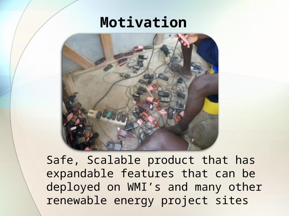
Motivation
Safe, Scalable product that has expandable features that can be deployed on WMI’s and many other renewable energy project sites
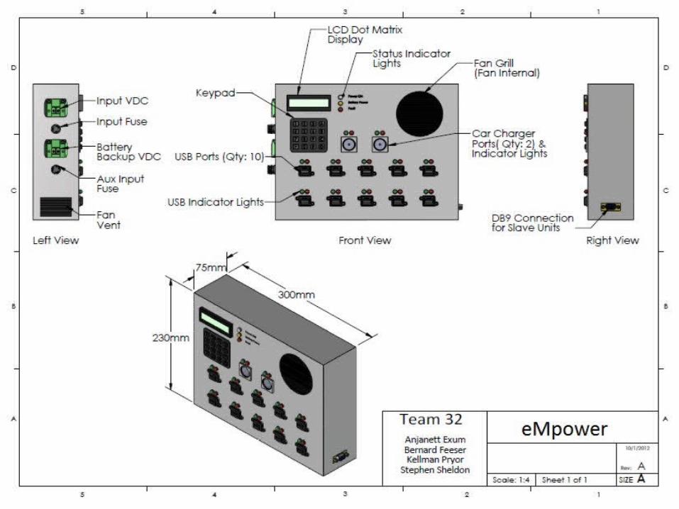
Solution
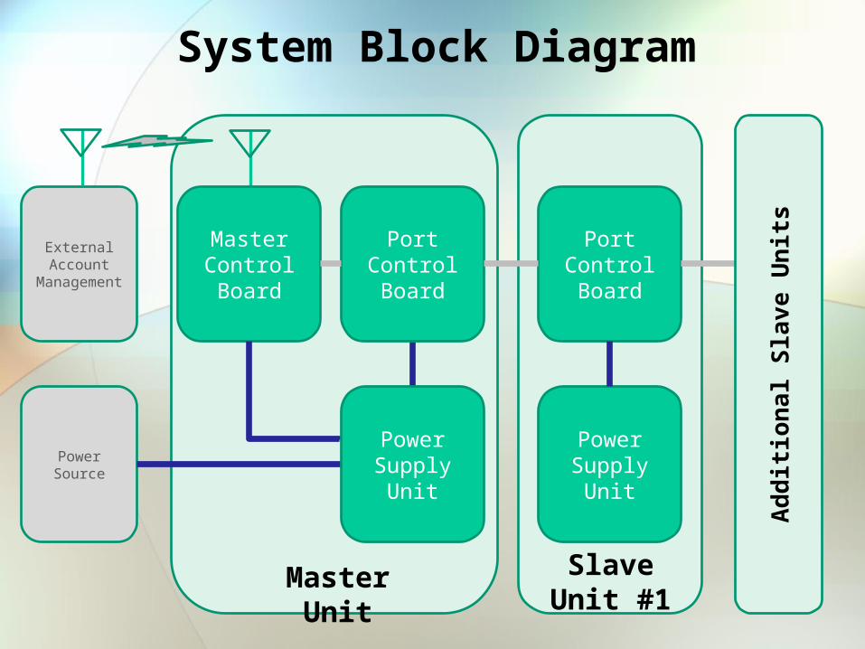
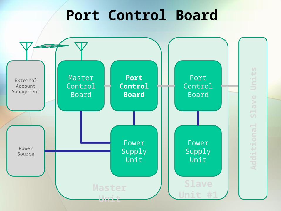
Master Control Board
External Account
Management
Power Source
Port Control Board
Power Supply Unit
Port Control Board
Master Unit Slave Unit #1
Power Supply Unit
Add
ition
al S
lave
Uni
ts
System Block Diagram

Master Control Board
Master Control Board
External Account
Management
Power Source
Port Control Board
Power Supply Unit
Port Control Board
Master Unit Slave Unit #1
Power Supply Unit
Add
ition
al S
lave
Uni
ts

Main Control Board Overview
20x4 LCD Screen GSM Module
4x4 Keypad SD Card
ATMega2560 Controller Board
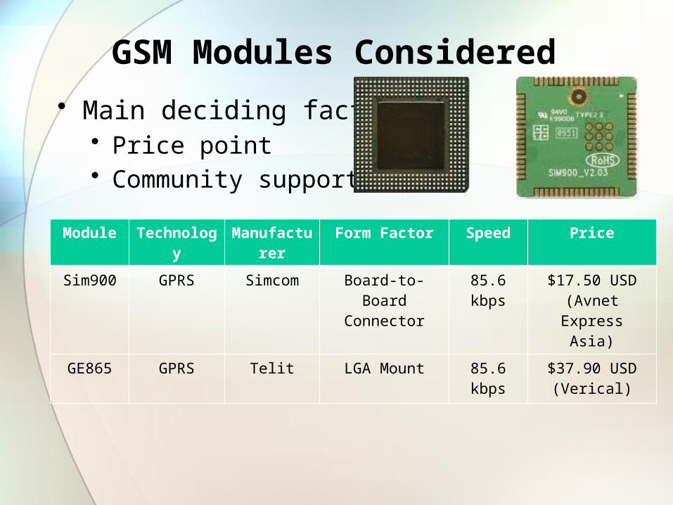
GSM Modules Considered
• Main deciding factors• Price point• Community support
Module Technology Manufacturer Form Factor Speed Price
Sim900 GPRS Simcom Board-to-Board Connector
85.6 kbps $17.50 USD (Avnet Express Asia)
GE865 GPRS Telit LGA Mount 85.6 kbps $37.90 USD (Verical)
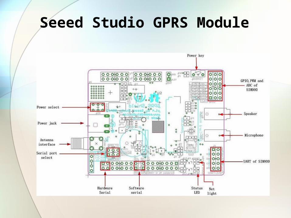
Seeed Studio GPRS Module
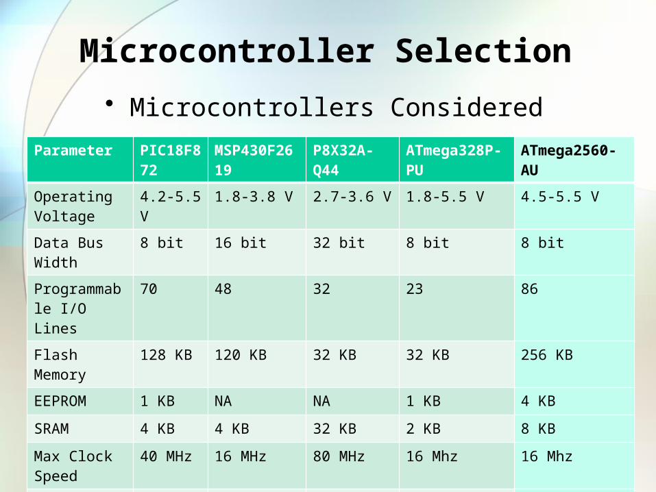
Microcontroller Selection
• Microcontrollers ConsideredParameter PIC18F872 MSP430F2619 P8X32A-Q44 ATmega328P-PU ATmega2560-AU
Operating Voltage
4.2-5.5 V 1.8-3.8 V 2.7-3.6 V 1.8-5.5 V 4.5-5.5 V
Data Bus Width 8 bit 16 bit 32 bit 8 bit 8 bit
Programmable I/O Lines
70 48 32 23 86
Flash Memory 128 KB 120 KB 32 KB 32 KB 256 KB
EEPROM 1 KB NA NA 1 KB 4 KB
SRAM 4 KB 4 KB 32 KB 2 KB 8 KB
Max Clock Speed
40 MHz 16 MHz 80 MHz 16 Mhz 16 Mhz
Cost $14.53 $13.15 $11.53 $2.24 $14.21
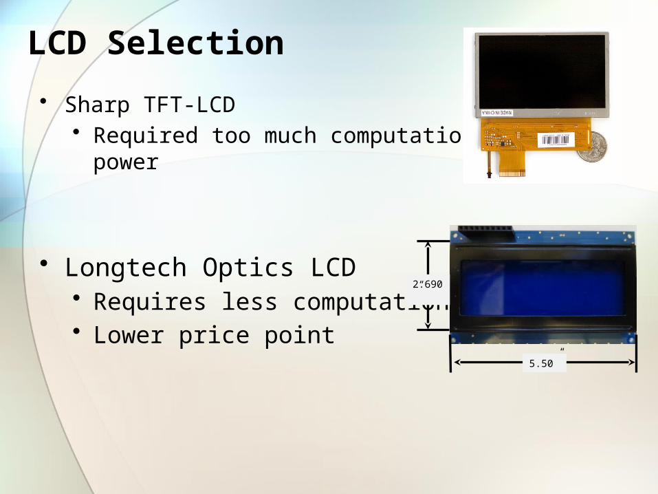
LCD Selection
• Sharp TFT-LCD• Required too much computational power
• Longtech Optics LCD• Requires less computational• Lower price point
2.690”
5.50”
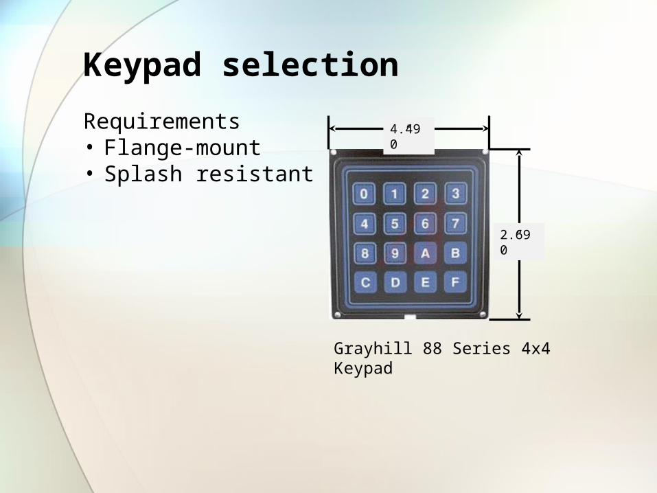
Keypad selection
Requirements• Flange-mount• Splash resistant
Grayhill 88 Series 4x4 Keypad
4.490”
2.690”
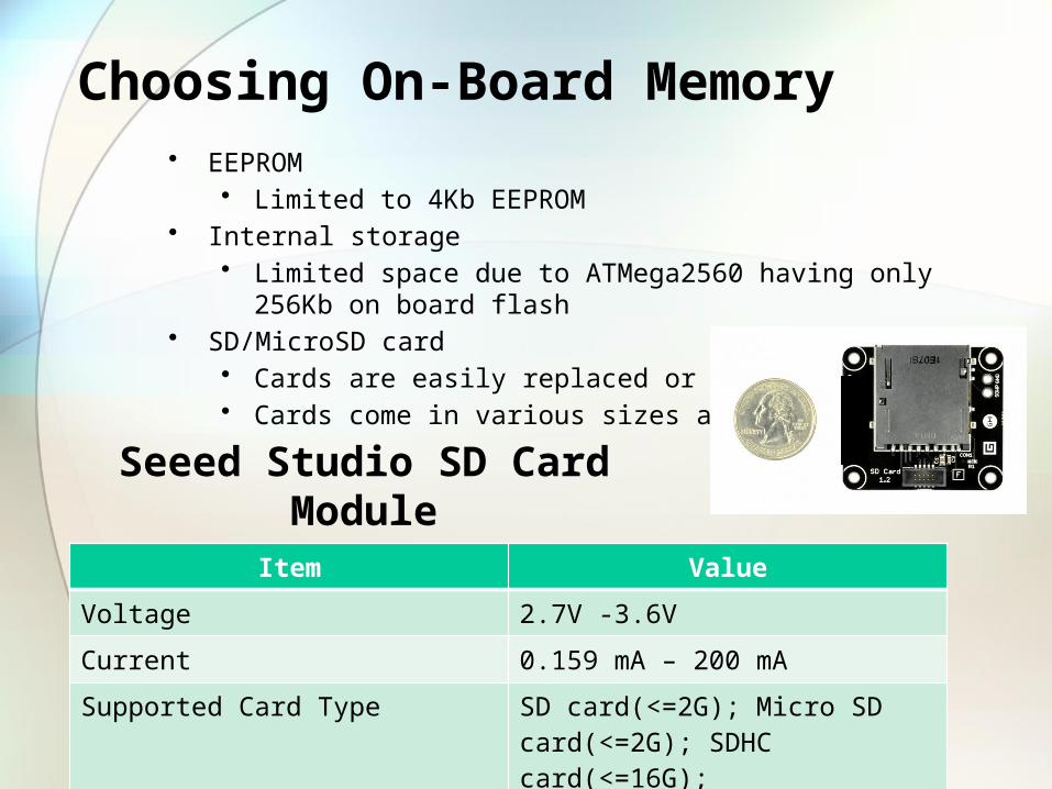
Choosing On-Board Memory• EEPROM
• Limited to 4Kb EEPROM• Internal storage
• Limited space due to ATMega2560 having only 256Kb on board flash• SD/MicroSD card
• Cards are easily replaced or upgraded• Cards come in various sizes and form factors
Item Value
Voltage 2.7V -3.6V
Current 0.159 mA – 200 mA
Supported Card Type SD card(<=2G); Micro SD card(<=2G); SDHC card(<=16G);
Seeed Studio SD Card Module
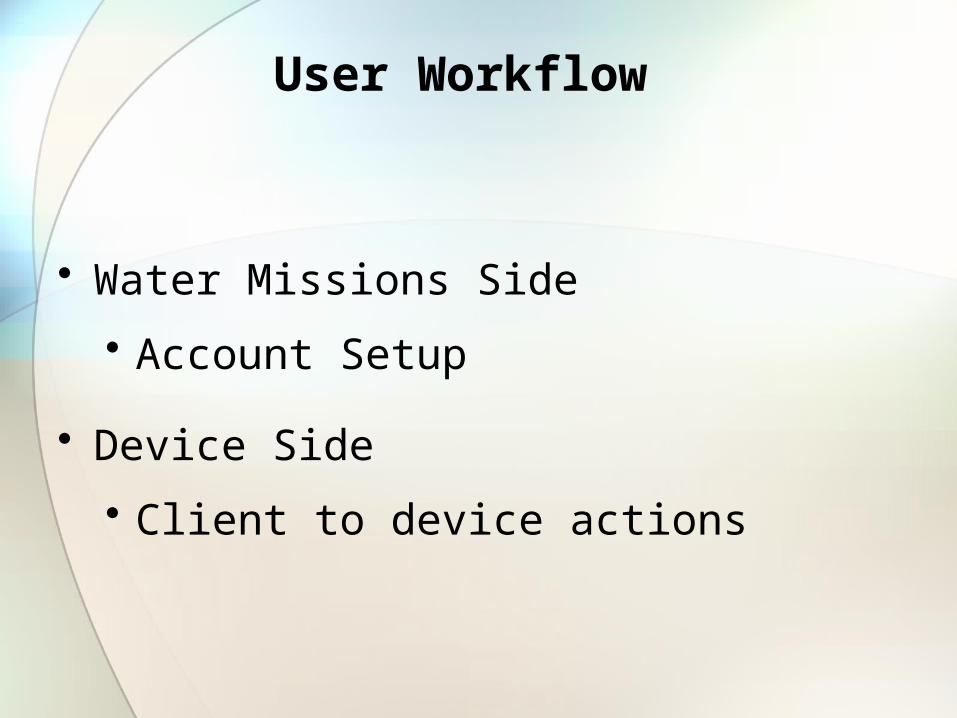
User Workflow
• Water Missions Side
• Account Setup
• Device Side
• Client to device actions
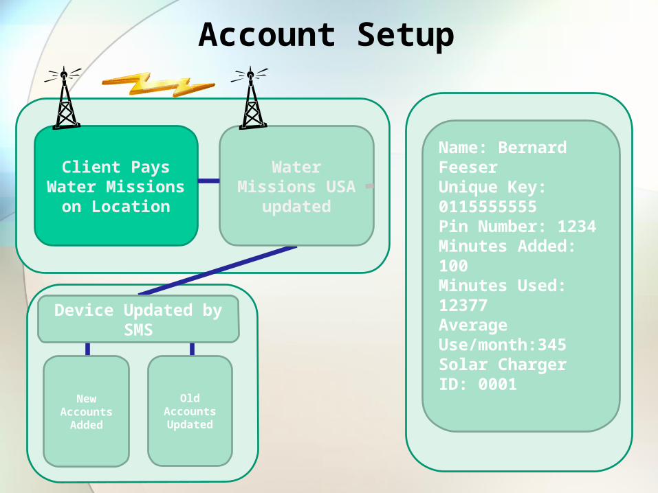
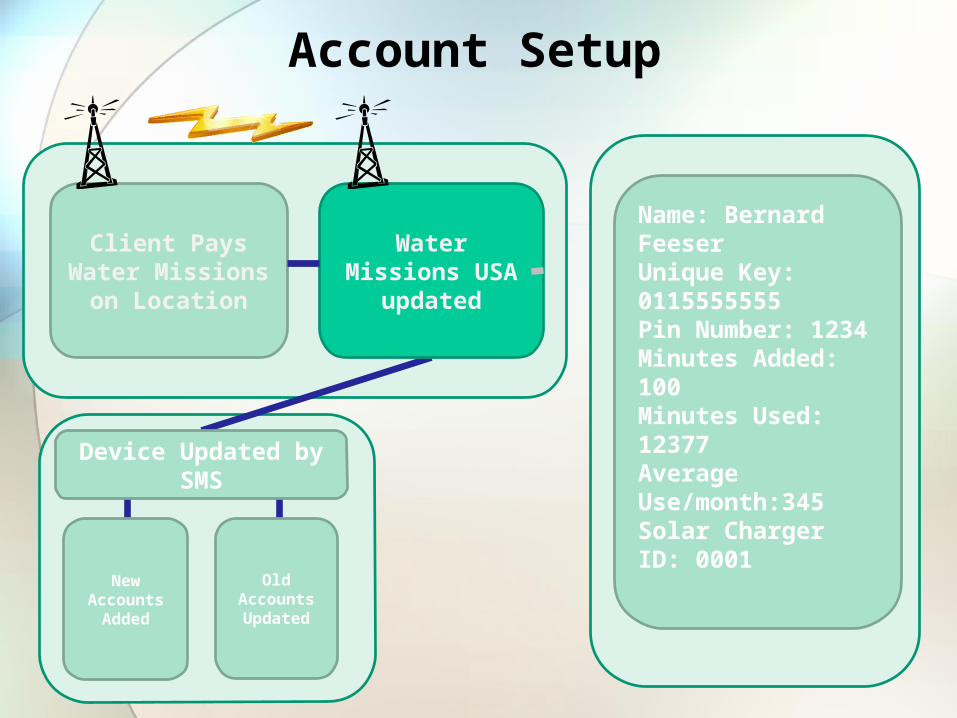
Account Setup
Client Pays Water Missions on Location
New Accounts Added
Water Missions USA updated
Device Updated by SMS
Name: Bernard FeeserUnique Key: 0115555555Pin Number: 1234Minutes Added: 100Minutes Used: 12377Average Use/month:345Solar Charger ID: 0001
Old Accounts Updated
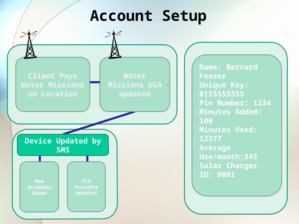
Account Setup
Client Pays Water Missions on Location
New Accounts Added
Water Missions USA updated
Device Updated by SMS
Name: Bernard FeeserUnique Key: 0115555555Pin Number: 1234Minutes Added: 100Minutes Used: 12377Average Use/month:345Solar Charger ID: 0001
Old Accounts Updated
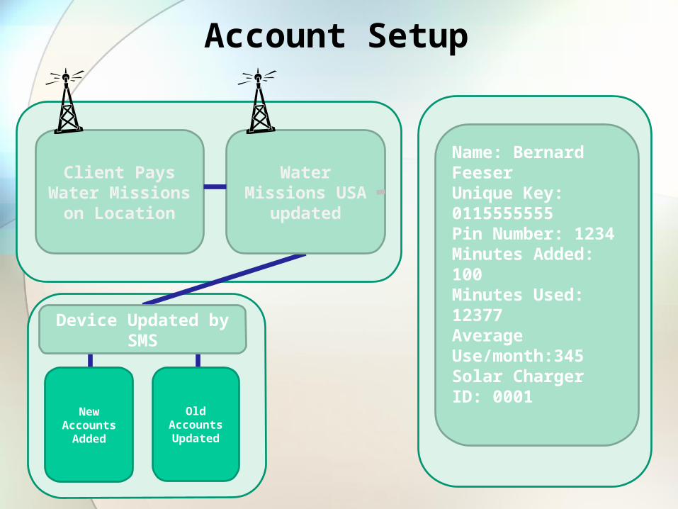
Account Setup
Client Pays Water Missions on Location
New Accounts Added
Water Missions USA updated
Device Updated by SMS
Name: Bernard FeeserUnique Key: 0115555555Pin Number: 1234Minutes Added: 100Minutes Used: 12377Average Use/month:345Solar Charger ID: 0001
Old Accounts Updated
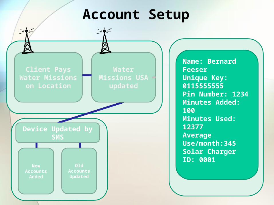
Account Setup
Client Pays Water Missions on Location
New Accounts Added
Water Missions USA updated
Device Updated by SMS
Name: Bernard FeeserUnique Key: 0115555555Pin Number: 1234Minutes Added: 100Minutes Used: 12377Average Use/month:345Solar Charger ID: 0001
Old Accounts Updated
Account Setup
Client Pays Water Missions on Location
New Accounts Added
Water Missions USA updated
Device Updated by SMS
Name: Bernard FeeserUnique Key: 0115555555Pin Number: 1234Minutes Added: 100Minutes Used: 12377Average Use/month:345Solar Charger ID: 0001
Old Accounts Updated
Account Setup
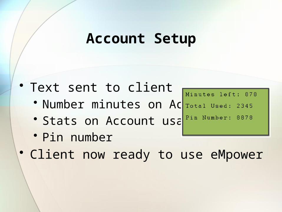
• Text sent to client• Number minutes on Account• Stats on Account usage• Pin number
• Client now ready to use eMpower

Device Side (Client)
• Enters phone number
• Enters pin
• Main menu
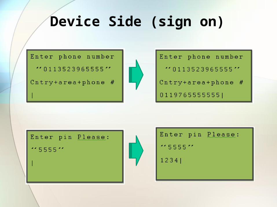
Device Side (sign on)

Device Side (Menu)
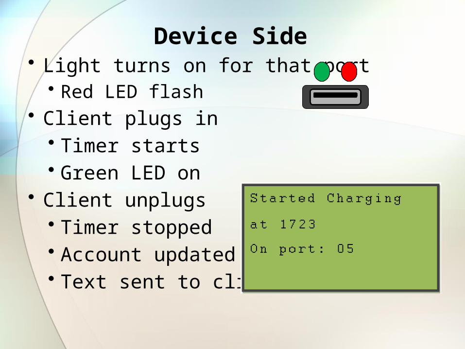
Device Side• Light turns on for that port
• Red LED flash• Client plugs in
• Timer starts• Green LED on
• Client unplugs• Timer stopped • Account updated • Text sent to client
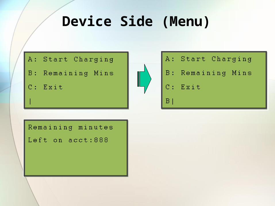
Device Side (Menu)
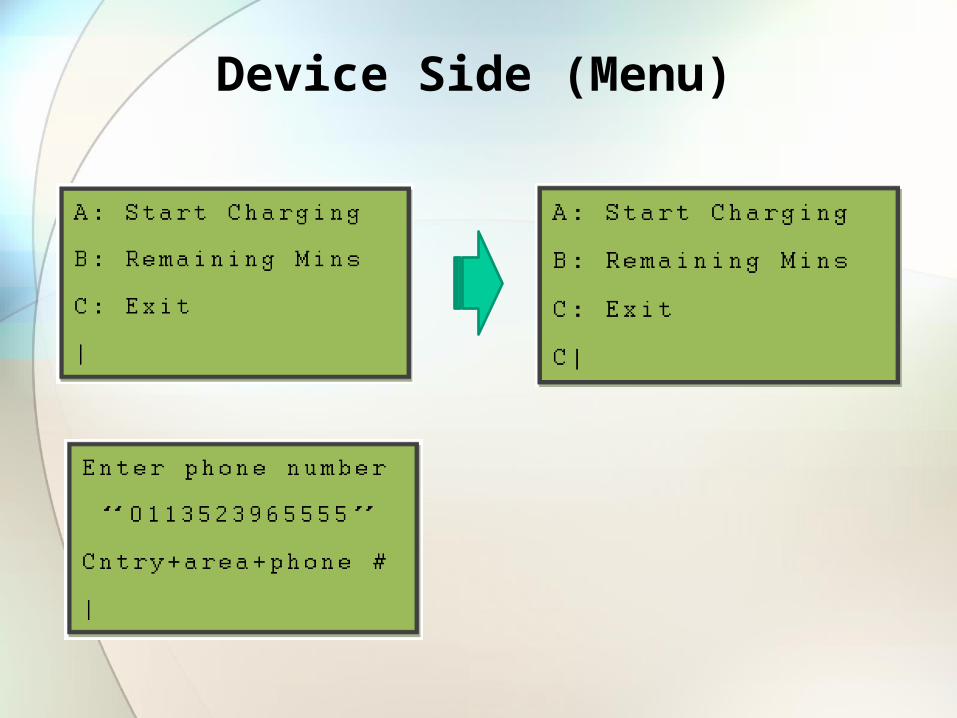
Device Side (Menu)
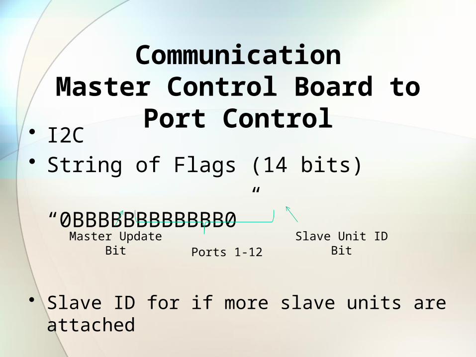
CommunicationMaster Control Board to Port Control
• I2C• String of Flags (14 bits) “0BBBBBBBBBBBB0”
• Slave ID for if more slave units are attached
Master UpdateBit
Slave Unit IDBitPorts 1-12
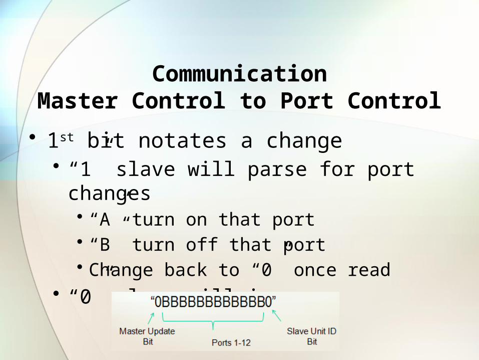
CommunicationMaster Control to Port Control
• 1st bit notates a change • “1” slave will parse for port changes
• “A” turn on that port • “B” turn off that port• Change back to “0” once read
• “0” slave will ignore
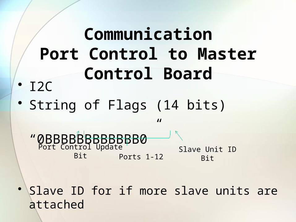
CommunicationPort Control to Master Control Board
• I2C• String of Flags (14 bits) “0BBBBBBBBBBBB0”
• Slave ID for if more slave units are attached
Port Control UpdateBit
Slave Unit IDBitPorts 1-12
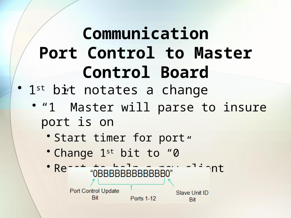
CommunicationPort Control to Master Control Board
• 1st bit notates a change• “1” Master will parse to insure port is on
• Start timer for port• Change 1st bit to “0”• Reset to help a new client
Port Control Board
Master Control Board
External Account
Management
Power Source
Port Control Board
Power Supply Unit
Port Control Board
Master Unit Slave Unit #1
Power Supply Unit
Add
ition
al S
lave
Uni
ts
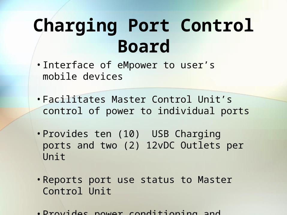
Charging Port Control Board
• Interface of eMpower to user’s mobile devices
• Facilitates Master Control Unit’s control of power to individual ports
• Provides ten (10) USB Charging ports and two (2) 12vDC Outlets per Unit
• Reports port use status to Master Control Unit
• Provides power conditioning and circuit protection to charging ports
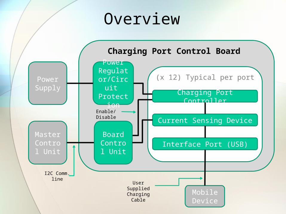
(x 12) Typical per port
Charging Port Control Board
Power Supply
Power Regulator/
Circuit Protection
Current Sensing Device
Master Control
Unit
Mobile Device
Interface Port (USB)Board Control
Unit
Charging Port Controller
I2C Comm. line
User Supplied Charging
Cable
Enable/Disable
Overview
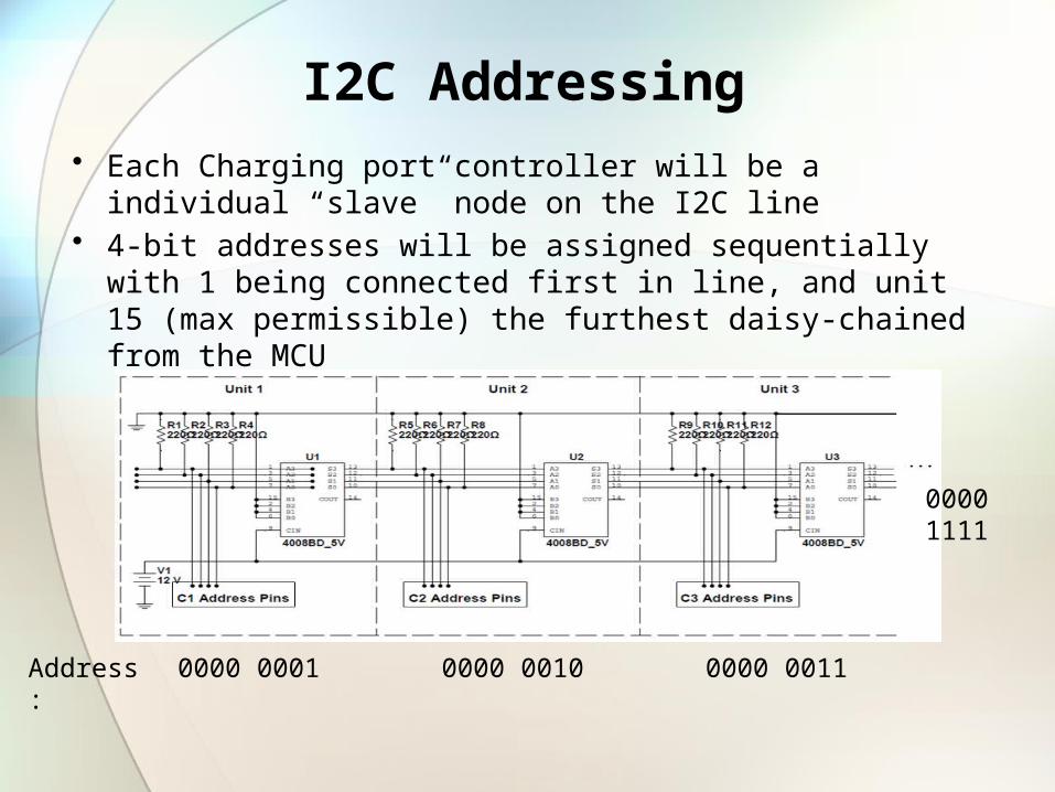
I2C Addressing
• Each Charging port controller will be a individual “slave” node on the I2C line
• 4-bit addresses will be assigned sequentially with 1 being connected first in line, and unit 15 (max permissible) the furthest daisy-chained from the MCU
0000 0001 0000 0010 0000 0011Address:
0000 1111
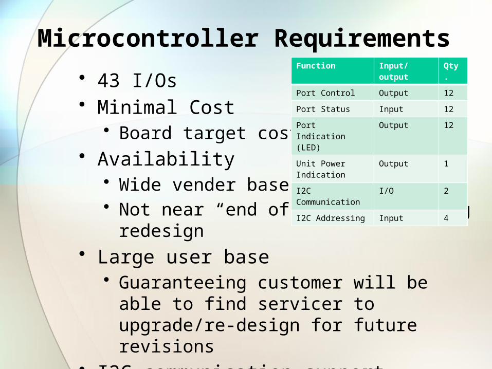
Microcontroller Requirements
• 43 I/Os• Minimal Cost
• Board target cost is $33• Availability
• Wide vender base• Not near “end of life”, requiring redesign
• Large user base• Guaranteeing customer will be able to find servicer to
upgrade/re-design for future revisions• I2C communication support
Function Input/output Qty.
Port Control Output 12
Port Status Input 12
Port Indication (LED) Output 12
Unit Power Indication Output 1
I2C Communication I/O 2
I2C Addressing Input 4
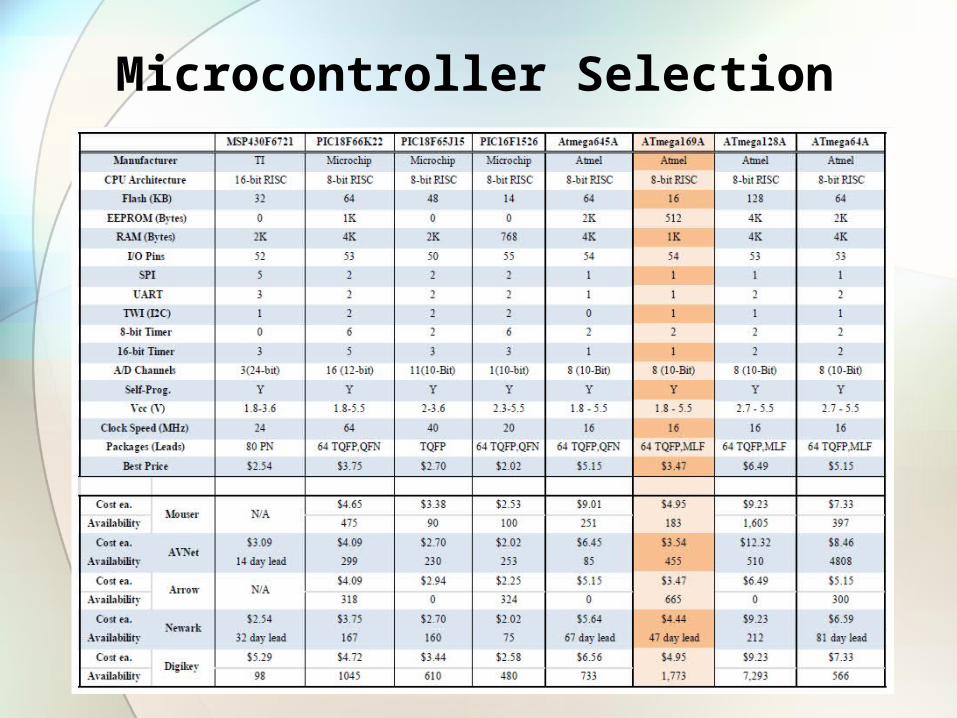
Microcontroller Selection
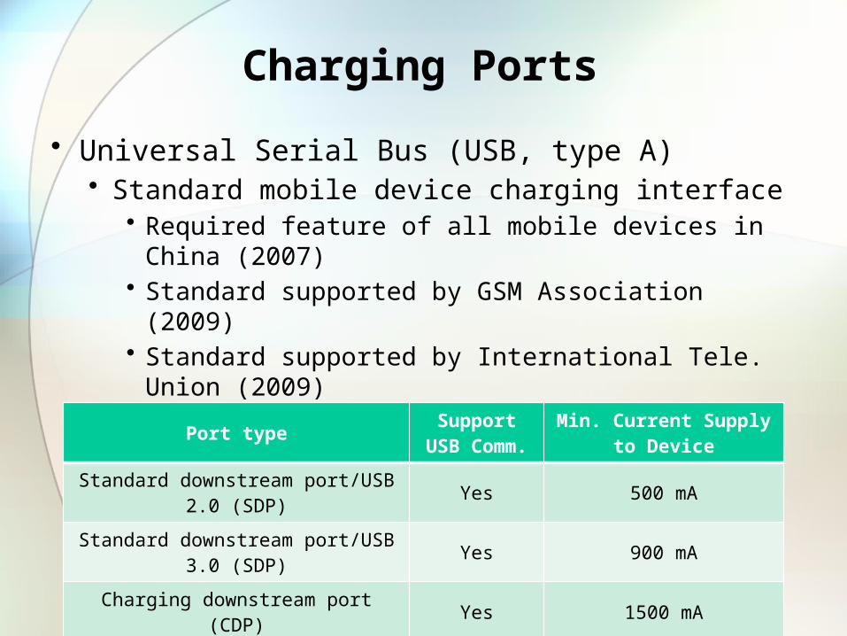
Charging Ports
• Universal Serial Bus (USB, type A)• Standard mobile device charging interface
• Required feature of all mobile devices in China (2007)• Standard supported by GSM Association (2009)• Standard supported by International Tele. Union (2009)
• Power requirements
Port type Support USB Comm. Min. Current Supply to Device
Standard downstream port/USB 2.0 (SDP) Yes 500 mA
Standard downstream port/USB 3.0 (SDP) Yes 900 mA
Charging downstream port (CDP) Yes 1500 mA
Dedicated charging port (DCP) No 1500 mA
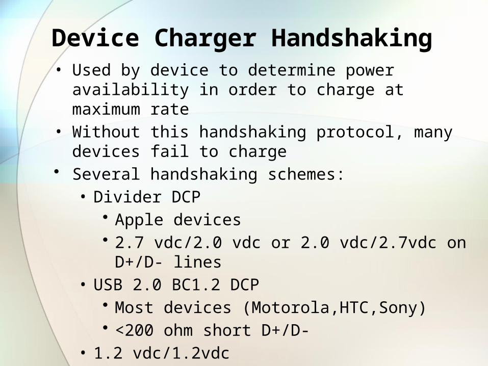
Device Charger Handshaking• Used by device to determine power availability in order to charge at
maximum rate• Without this handshaking protocol, many devices fail to charge• Several handshaking schemes:
• Divider DCP• Apple devices• 2.7 vdc/2.0 vdc or 2.0 vdc/2.7vdc on D+/D- lines
• USB 2.0 BC1.2 DCP• Most devices (Motorola,HTC,Sony)• <200 ohm short D+/D-
• 1.2 vdc/1.2vdc• Many Samsung devices• 1.2 vdc/1.2vdc on D+/D-
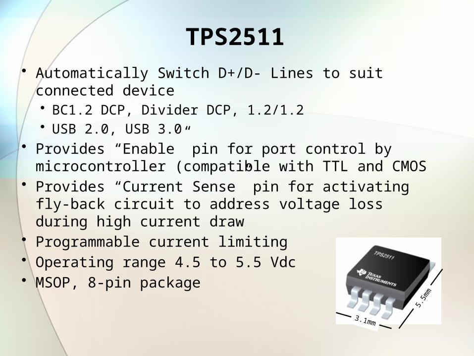
TPS2511• Automatically Switch D+/D- Lines to suit connected device
• BC1.2 DCP, Divider DCP, 1.2/1.2• USB 2.0, USB 3.0
• Provides “Enable” pin for port control by microcontroller (compatible with TTL and CMOS
• Provides “Current Sense” pin for activating fly-back circuit to address voltage loss during high current draw
• Programmable current limiting• Operating range 4.5 to 5.5 Vdc• MSOP, 8-pin package
3.1mm
5.5m
m
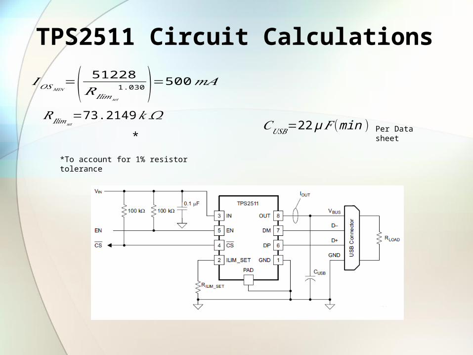
TPS2511 Circuit Calculations
*
𝑅𝐼𝑙𝑖𝑚𝑠𝑒𝑡=73.2149𝑘𝛺
𝐼𝑂𝑆𝑀𝐼𝑁=( 51228
𝑅𝐼𝑙𝑖𝑚𝑠𝑒𝑡
1.030 )=500𝑚𝐴
*To account for 1% resistor tolerance
𝐶𝑈𝑆𝐵=22µ𝐹 (min ) Per Data sheet
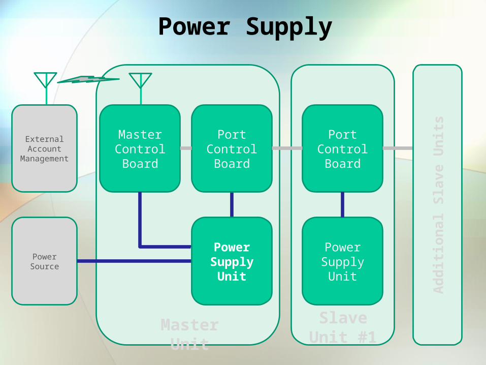
Power Supply
Master Control Board
External Account
Management
Power Source
Port Control Board
Power Supply Unit
Port Control Board
Master Unit Slave Unit #1
Power Supply Unit
Add
ition
al S
lave
Uni
ts

Power Regulation Specification
• Wide input voltage of 30 VDC– 300 VDC• Battery Input of 12 VDC – 24 VDC• Output voltage to devices of 12 VDC
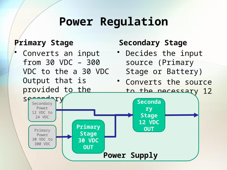
Power Regulation
Primary Stage• Converts an input from 30 VDC
– 300 VDC to the a 30 VDC Output that is provided to the secondary stage
Secondary Stage• Decides the input source
(Primary Stage or Battery)• Converts the source to the
necessary 12 VDC
Primary Power30 VDC to 300 VDC
Power Supply
Primary Stage
30 VDC OUT
Secondary Power
12 VDC to 24 VDC
SecondaryStage
12 VDC OUT
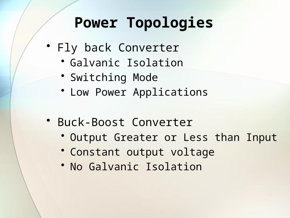
Power Topologies
• Fly back Converter• Galvanic Isolation• Switching Mode• Low Power Applications
• Buck-Boost Converter• Output Greater or Less than Input• Constant output voltage• No Galvanic Isolation

Primary Stage Schematic
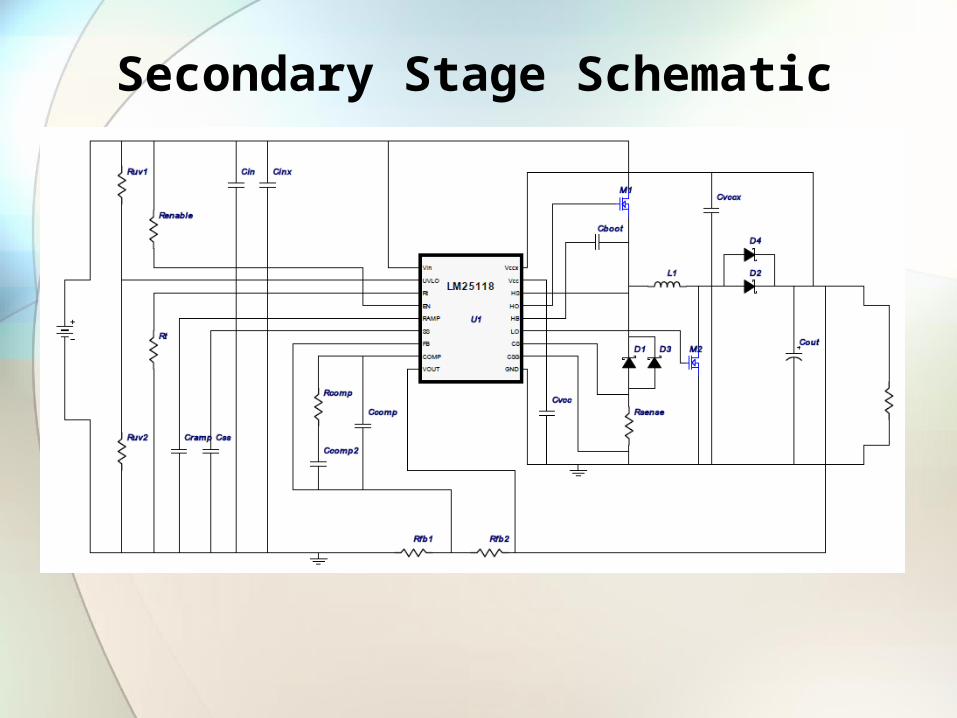
Secondary Stage Schematic
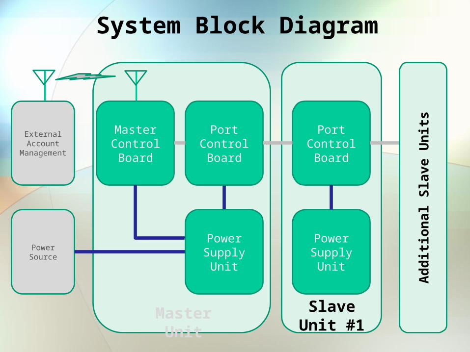
System Block Diagram
Master Control Board
External Account
Management
Power Source
Port Control Board
Power Supply Unit
Port Control Board
Master Unit Slave Unit #1
Power Supply Unit
Add
ition
al S
lave
Uni
ts
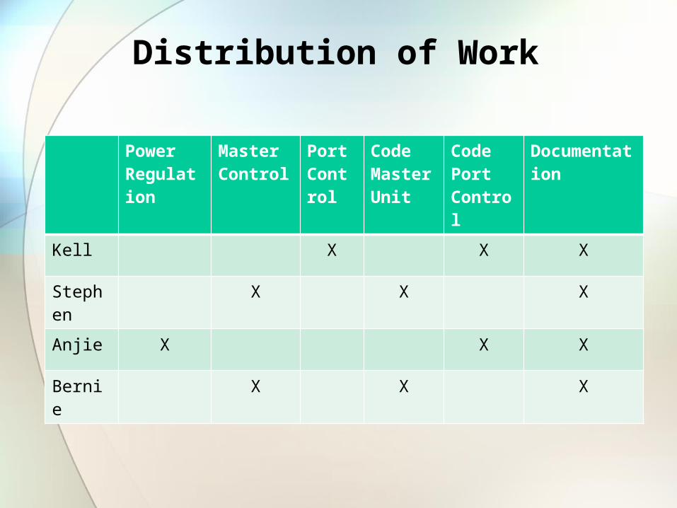
Distribution of Work
Power Regulation
Master Control
Port Control
Code Master Unit
Code Port Control
Documentation
Kell X X X
Stephen X X X
Anjie X X X
Bernie X X X
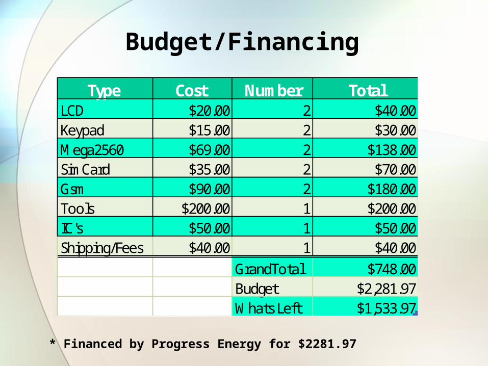
Budget/Financing
Type Cost Number TotalLCD $20.00 2 $40.00Keypad $15.00 2 $30.00Mega2560 $69.00 2 $138.00SimCard $35.00 2 $70.00Gsm $90.00 2 $180.00Tools $200.00 1 $200.00IC's $50.00 1 $50.00Shipping/Fees $40.00 1 $40.00
GrandTotal $748.00Budget $2,281.97Whats Left $1,533.97
* Financed by Progress Energy for $2281.97

Progress
Master
Board
Port Con
trol B
oard
Power/
Regula
tionCod
ing
Testing
Researc
hDesi
gn0%
10%
20%
30%
40%
50%
60%
70%
80%
90%
100%
Project completion
Project completion
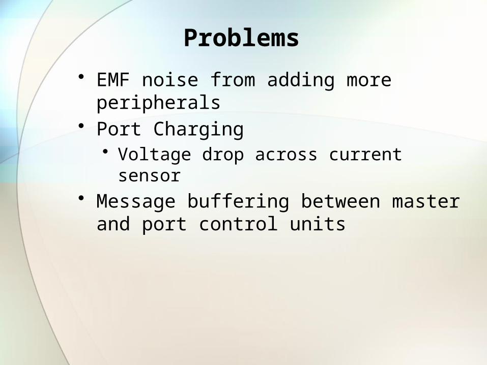
Problems
• EMF noise from adding more peripherals • Port Charging
• Voltage drop across current sensor• Message buffering between master and port control
units