TRAILING ARM ................................................... 12LATERAL LINK .................................................... 12CONTROL ROD .................................................. 12
Assembly ................................................................ 13SERVICE DATA AND SPECIFICATIONS (SDS) ...... 14
● When installing each rubber part, final tightening must becarried out under unladen condition* with tires on ground.Oil will shorten the life of rubber bushings. Be sure to wipeoff any spilled oil.*: Fuel, radiator coolant and engine oil full. Spare tire, jack,hand tools and mats in designated positions.
● Use flare nut wrench when removing or installing braketubes.
● After installing removed suspension parts, check wheelalignment.
● Do not jack up at the trailing arm and lateral link.● Always torque brake lines when installing.● Lock nuts are unreusable parts; always use new ones.
When replacing, do not wipe the oil off of the new lock nut before tightening.
Check axle and suspension parts for excessive play, wear or dam-age.● Shake each rear wheel to check for excessive play.● Retighten all nuts and bolts to the specified torque.
● Check shock absorber for oil leakage or other damage.● Check wheelarch height. Refer to RSU-15, "Wheelarch Height
(Unladen*)" .
Rear Wheel Alignment EES000CH
Before checking rear wheel alignment, be sure to make a preliminary inspection (Unladen*).*: Fuel, radiator coolant and engine oil full. Spare tire, jack, hand tools and mats in designated positions.
PRELIMINARY INSPECTION1. Check tires for wear and improper inflation.2. Check wheels for deformation, cracks and other damage. If
deformed, remove wheel and check wheel runout.a. Remove tire from wheel and mount wheel on a tire balance
machine.b. Set dial indicator as shown in the illustration.
3. Check front wheel bearings for looseness.4. Check front suspension for looseness.5. Check steering linkage for looseness.6. Check that front shock absorbers work properly.7. Check vehicle wheelarch height (unladen*). Refer to RSU-15, "Wheelarch Height (Unladen*)" .
● *: Fuel, radiator coolant and engine oil full. Spare tire, jack, hand tools and mats in designated posi-tions.
Tightening torque : Refer to RSU-6, "Compo-nents" .
SMA525A
SMA113
Wheel runout (Dial indi-cator value)
: Refer to WT-6, "Road
Wheel" .
SFA975B
RSU-8
REAR SUSPENSION ASSEMBLY
CAMBERCamber is preset at factory and cannot be adjusted.
1. Measure camber of both right-hand and left-hand wheels with asuitable alignment gauge.
2. If the camber is not within specification, inspect and replace anydamaged or worn rear suspension parts.
TOE-INToe-in is preset at factory and cannot be adjusted.Measure toe-in using following procedure. If out of specifica-tion, inspect and replace any damaged or worn rear suspensionparts.WARNING:● Always perform the following procedure on a flat surface.● Make sure that no person is in front of the vehicle before
pushing it.1. Bounce rear of vehicle up and down to stabilize the posture.2. Push the vehicle straight ahead about 5 m (16 ft).
3. Put a mark on base line of the tread (rear side) of both tires atthe same height of hub center. This mark is a measuring point.
4. Measure distance “A” (rear side).5. Push the vehicle slowly ahead to rotate the wheels 180 degrees
(1/2 turn).If the wheels have rotated more than 180 degrees (1/2 turn), trythe above procedure again from the beginning. Never pushvehicle backward.6. Measure distance “B” (front side).
Camber : Refer to RSU-15, "Rear
Wheel Alignment (Unladen*)" .
SFA948A
SFA614B
Total toe-in : A − BRefer to RSU-15, "Rear
Wheel Alignment (Unladen*)" .
SFA234AC
REMOVAL AND INSTALLATION
RSU-9
C
D
F
G
H
I
J
K
L
M
A
B
RSU
REMOVAL AND INSTALLATION PFP:00000
Removal and Installation EES000CI
REMOVALCAUTION:● Before removing the rear suspension assembly, disconnect
the ABS wheel sensor from the assembly. Failure to do somay result in damaged sensor wires and sensor becominginoperative.
● Drain brake fluid before disconnecting brake lines.1. Disconnect brake hydraulic lines and parking brake cables at
toggle levers. (Models with drum brakes.)2. Disconnect brake hydraulic lines and parking brake cables from
calipers and remove brake calipers and rotors. (Models with discbrakes.)
3. Disconnect ABS wheel sensor, if equipped.4. Using a transmission jack, raise torsion beam a little, and
remove nuts and bolts from the trailing arms, shock absorberassemblies (lower side) and lateral link.
5. Lower transmission jack and remove suspension.6. Remove luggage compartment trim. Refer to EI-34, "Removal
INSTALLATIONCAUTION:● Refill with new brake fluid DOT 3.● Never reuse drained brake fluid.1. Attach torsion beam at trailing arm and lateral link to vehicle. Do
not tighten bolts at this time.
ARA046
ARA052
WSU007
ARA051
RSU-10
REMOVAL AND INSTALLATION
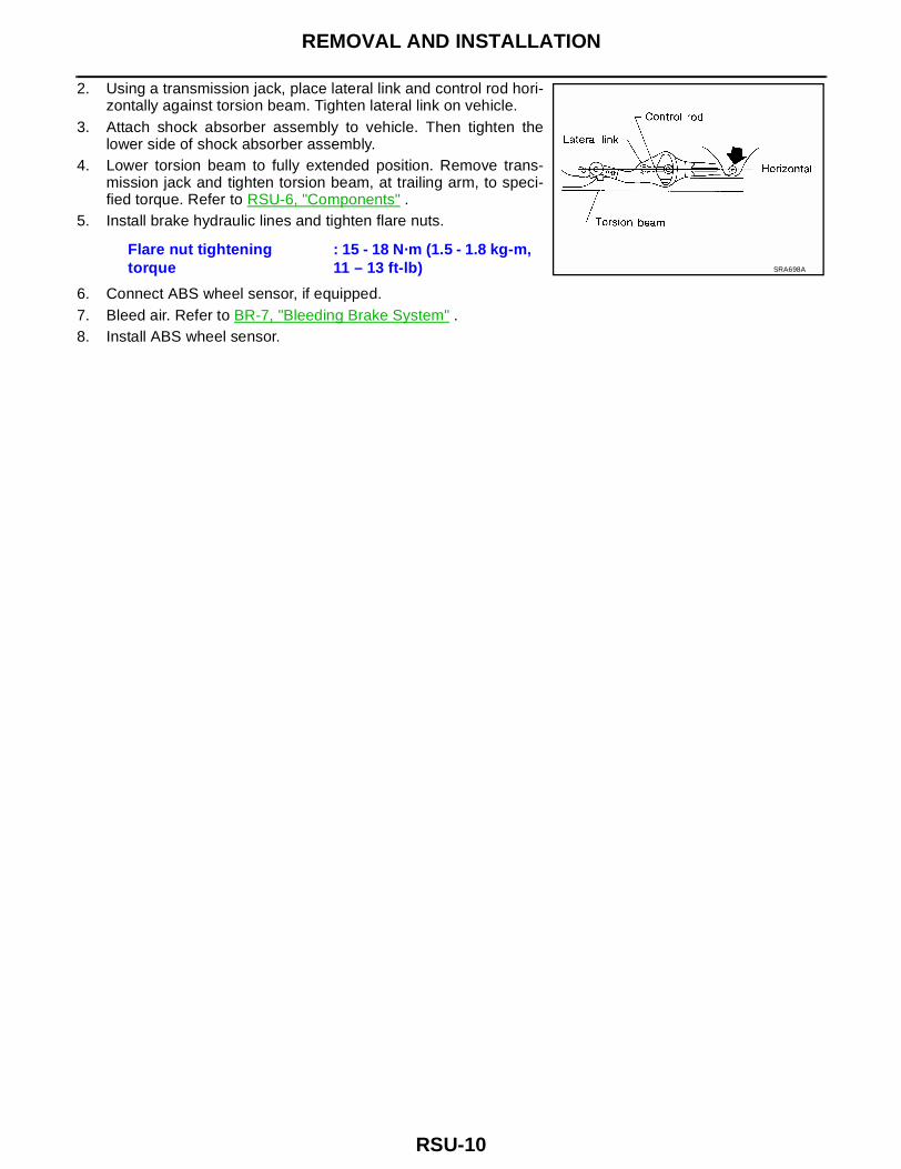
2. Using a transmission jack, place lateral link and control rod hori-zontally against torsion beam. Tighten lateral link on vehicle.
3. Attach shock absorber assembly to vehicle. Then tighten thelower side of shock absorber assembly.
4. Lower torsion beam to fully extended position. Remove trans-mission jack and tighten torsion beam, at trailing arm, to speci-fied torque. Refer to RSU-6, "Components" .
5. Install brake hydraulic lines and tighten flare nuts.
6. Connect ABS wheel sensor, if equipped.7. Bleed air. Refer to BR-7, "Bleeding Brake System" .8. Install ABS wheel sensor.
Remove shock absorber upper and lower fixing nuts.Do not remove piston rod lock nut on vehicle.
Disassembly EES000CK
1. Set shock absorber in vise, then loosen piston rod lock nut.Do not remove piston rod lock nut at this time.
2. Compress spring with Tool so that the shock absorber upperspring seat can be turned by hand.WARNING:Make sure that the pawls of the two spring compressors arefirmly hooked on the spring. The spring compressors mustbe tightened alternately so as not to tilt the spring.
3. Remove piston rod lock nut.
Inspection EES000CL
SHOCK ABSORBER ASSEMBLY● Check for smooth operation through a full stroke, both compression and extension.● Check for oil leakage on welded or gland packing portions.● Check piston rod for cracks, deformation or other damage.
Replace if necessary.
UPPER RUBBER SEAT AND BUSHINGCheck rubber parts for deterioration or cracks.Replace if necessary.
COIL SPRINGCheck for cracks, deformation or other damage. Replace if necessary.
Assembly EES000CM
● Locate upper spring seat as shown.
● When installing coil spring, be careful not to reverse top and bot-tom direction. (Top end is flat.)
● When installing coil spring on shock absorber, it must be posi-tioned as shown.CAUTION:Do not reuse piston rod lock nut.
SRA806A
WSU008
SFA436B
RSU-12
TORSION BEAM, LATERAL LINK AND CONTROL ROD
TORSION BEAM, LATERAL LINK AND CONTROL ROD PFP:55130
Disassembly EES000CN
● Remove torsion beam assembly. Refer to RSU-9, "REMOVAL" .● Remove lateral link and control rod from torsion beam.
Inspection EES000CO
● Check for cracks, distortion or other damage. Replace if neces-sary.
● Check all rubber parts for wear, cracks or deformation. Replaceif necessary.
Rubber Bushing Replacement EES000CP
TRAILING ARMTrailing arm bushings are press fit and must be centered properly intrailing arm collars.1. Press out old bushing from trailing arm collar.2. Press in new bushing until inside edge of bushing is 16.7 to 17.7
mm (0.66 to 0.70 in) from inside edge of trailing arm.● Do not allow bushing to incline more than 1 degree.● During installation, do not allow trailing arm to bend or twist.
LATERAL LINKLateral link bushings are press fit. The large lateral link bushing isdirectional and must be installed in a specific position.1. Remove lateral link.2. Press out bushings. Note installation position of large bushing
before removing.3. Press in small bushing until bushing is centered in lateral link
collar.4. Press in large bushing until bushing is centered in lateral link
collar.a. Position bushing on lateral link collar.b. Angle between bushing centerline and collar centerline must be
within 3 degrees as shown in illustration.
CONTROL RODControl rod bushings are not replaceable. If bushings are worn or damaged, replace control rod.
Standard length : "A" 207 - 208 mm (8.15 - 8.19 in)"B" 394 - 395 mm (15.51 - 15.55 in)"C" 601 - 603 mm (23.66 - 23.74 in)"D" 106 - 108 mm (4.17 - 4.25 in)
SSU025
ARA063
ARA054
TORSION BEAM, LATERAL LINK AND CONTROL ROD
RSU-13
C
D
F
G
H
I
J
K
L
M
A
B
RSU
Assembly EES000CQ
1. Temporarily assemble lateral link and control rod.● When installing the control rod, connect the bushing with the
smaller inner diameter to the lateral link.
2. Temporarily install lateral link and control rod on torsion beam.● When installing, place lateral link with the arrow topside.
3. Place lateral link and control rod horizontally against torsionbeam, and tighten to the specified torque.
4. Install torsion beam assembly. Refer to RSU-9, "INSTALLA-TION" .
SRA793A
SRA701A
SSU024
RSU-14
SERVICE DATA AND SPECIFICATIONS (SDS)
SERVICE DATA AND SPECIFICATIONS (SDS) PFP:00030
SERVICE DATA AND SPECIFICATIONS (SDS)
RSU-15
C
D
F
G
H
I
J
K
L
M
A
B
RSU
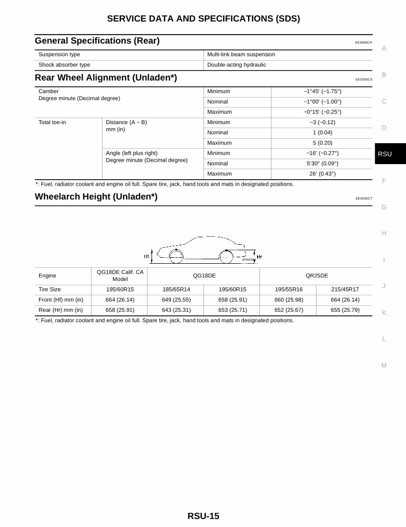
General Specifications (Rear) EES000CR
Rear Wheel Alignment (Unladen*) EES000CS
*: Fuel, radiator coolant and engine oil full. Spare tire, jack, hand tools and mats in designated positions.
Wheelarch Height (Unladen*) EES000CT
*: Fuel, radiator coolant and engine oil full. Spare tire, jack, hand tools and mats in designated positions.
Suspension type Multi-link beam suspension
Shock absorber type Double-acting hydraulic
CamberDegree minute (Decimal degree)
Minimum −1°45′ (−1.75°)
Nominal −1°00′ (−1.00°)
Maximum −0°15′ (−0.25°)
Total toe-in Distance (A − B)mm (in)
Minimum −3 (−0.12)
Nominal 1 (0.04)
Maximum 5 (0.20)
Angle (left plus right)Degree minute (Decimal degree)