13
www.matrixmultimedia.com E-system design suite

www.matrixmultimedia.com
E-system design suite
2 Copyright © 2012 Matrix Multimedia Ltd.
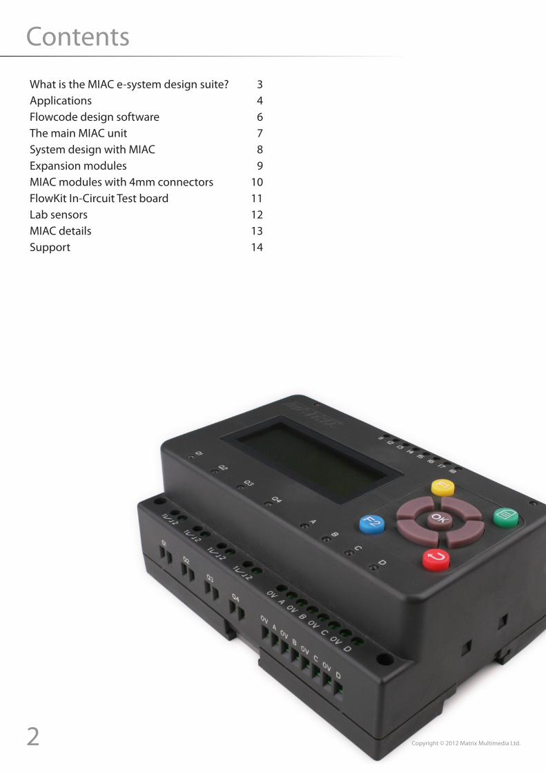
Contents
What is the MIAC e-system design suite? 3Applications 4Flowcode design software 6The main MIAC unit 7System design with MIAC 8Expansion modules 9MIAC modules with 4mm connectors 10FlowKit In-Circuit Test board 11Lab sensors 12MIAC details 13Support 14

3Copyright © 2012 Matrix Multimedia Ltd.
What is the MIAC e-system design suite?MIAC modules and software allow designers to quickly develop control and data-logging
systems
…
Each MIAC module contains a block of electronics which you would typically find in an industrial electronic control or data acquisition system.
The 10 modules in the range connect together using the CAN bus. The modules can be positioned next to each other or several hundred metres apart. Power is applied locally. The modules also link into a wide range of other communications systems: GSM, Bluetooth, TCP/IP, ZigBee, etc.
The system is programmed using Flowcode software. Flowcode is a graphical programming environment based on flowcharts. Flowcode includes ‘drivers’ for all of the MIAC modules making programming the system easy.
Communication between modules is taken care of by Flowcode. To add a module (or second MIAC) to the system just add the module to the Flowcode simulation. Flowcode takes care of low level CAN bus commands so no understanding of CAN is needed.
MIAC modules are compatible with a wide range of industrial sensors and add-ons that sit on 35mm ‘top hat’ DIN rails.
The great advantage of the MIAC system is that it provides a very flexible set of parts that can be used to create a vast range of electrical systems in a very short time.
Simple• Flowcode’s drag and drop interface means that no
programming experience is needed• Expand your system just by adding modules• The system connects using CAN bus, but no knowledge
of CAN is required
Rugged• 12 or 24V control operation• Meets IEC60950-1 industrial standard• Switch up to 240V AC
Scalable• Add up to 4 MIACs and 40 other modules within the
Flowcode work space for simple networks• Use a full CAN protocol to extend your network to 100
MIACs and numerous expansion modules• Grow your system as your needs change
Expandable• Connect to industrial sensors, controllers and other
DIN mounted subsystems• Link to other systems using TCP/IP, ZigBee, RS485, etc.• Link to your PC using Bluetooth, USB, RS232, etc.
Flexible• Used in education and in industry• Link to PC via USB and control with other software
packages like LabView, C++, etc.
4 Copyright © 2012 Matrix Multimedia Ltd.
Applications
Feed roller(DC motor)
Switches
Pneumatic clamp
Emergency stop relay
Emergency stop
Safety switch
CAN
Sensors
Turntable(stepper motor)
GSM network
Reflectivesensors
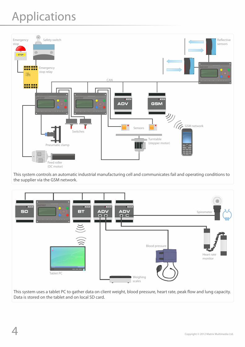
This system controls an automatic industrial manufacturing cell and communicates fail and operating conditions to the supplier via the GSM network.
Tablet PCWeighing scales
Blood pressure
Heart ratemonitor
Spirometer
This system uses a tablet PC to gather data on client weight, blood pressure, heart rate, peak flow and lung capacity. Data is stored on the tablet and on local SD card.

5Copyright © 2012 Matrix Multimedia Ltd.
Applications
Reflectivesensors Alarm
This control system uses ZigBee and the internet to allow control of lights, security, temperature and building access.
Motor
Air conditioning
Roller shutter door
Lights
Switches
Sensors
Controls
Internet
Alarm
Temperature humidity sensor CAN Office window blinds
Doors
Access control keypad
6 Copyright © 2012 Matrix Multimedia Ltd.
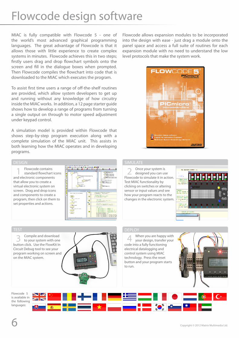
Flowcode design softwareMIAC is fully compatible with Flowcode 5 - one of the world’s most advanced graphical programming languages. The great advantage of Flowcode is that it allows those with little experience to create complex systems in minutes. Flowcode achieves this in two steps; firstly users drag and drop flowchart symbols onto the screen and fill in the dialogue boxes when prompted. Then Flowcode compiles the flowchart into code that is downloaded to the MIAC which executes the program.
To assist first time users a range of off-the-shelf routines are provided, which allow system developers to get up and running without any knowledge of how circuitry inside the MIAC works. In addition, a 12 page starter guide shows how to develop a range of programs from turning a single output on through to motor speed adjustment under keypad control.
A simulation model is provided within Flowcode that shows step-by-step program execution along with a complete simulation of the MIAC unit. This assists in both learning how the MIAC operates and in developing programs.
Flowcode allows expansion modules to be incorporated into the design with ease - just drag a module onto the panel space and access a full suite of routines for each expansion module with no need to understand the low level protocols that make the system work.
Flowcode contains standard flowchart icons
and electronic components that allow you to create a virtual electronic system on screen. Drag and drop icons and components to create a program, then click on them to set properties and actions.
1 Once your system is designed you can use
Flowcode to simulate it in action. Test MIAC functionality by clicking on switches or altering sensor or input values and see how your program reacts to the changes in the electronic system.
2
Compile and download to your system with one
button click. Use the FlowKit In Circuit Debug tool to see your program working on screen and on the MIAC system.
3 When you are happy with your design, transfer your
code into a fully functioning electrical datalogging and control system using MIAC technology. Press the reset button and your program starts to run.
4
DESIGN SIMULATE
TEST DEPLOY
Flowcode 5 is available in the following languages:
7Copyright © 2012 Matrix Multimedia Ltd.
The main MIAC unitBenefits• Flexible and expandable• Easy to program with flowcharts, C or assembly code• Physically and electrically rugged
Features• Programmable from USB• 8 digital or analogue inputs• 4 relay outputs, 4 transistor outputs with PWM• Compatible with LabView, Visual Basic and C compilers
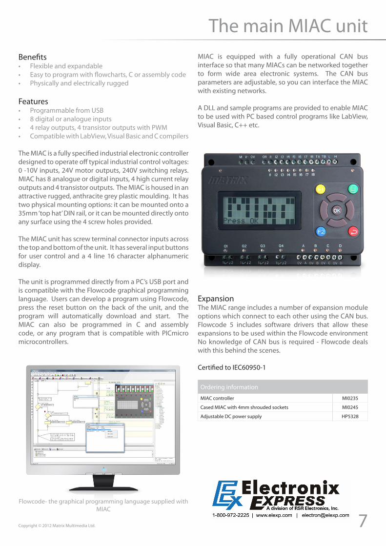
The MIAC is a fully specified industrial electronic controller designed to operate off typical industrial control voltages: 0 -10V inputs, 24V motor outputs, 240V switching relays. MIAC has 8 analogue or digital inputs, 4 high current relay outputs and 4 transistor outputs. The MIAC is housed in an attractive rugged, anthracite grey plastic moulding. It has two physical mounting options: it can be mounted onto a 35mm ‘top hat’ DIN rail, or it can be mounted directly onto any surface using the 4 screw holes provided.
The MIAC unit has screw terminal connector inputs across the top and bottom of the unit. It has several input buttons for user control and a 4 line 16 character alphanumeric display.
The unit is programmed directly from a PC’s USB port and is compatible with the Flowcode graphical programming language. Users can develop a program using Flowcode, press the reset button on the back of the unit, and the program will automatically download and start. The MIAC can also be programmed in C and assembly code, or any program that is compatible with PICmicro microcontrollers.
MIAC is equipped with a fully operational CAN bus interface so that many MIACs can be networked together to form wide area electronic systems. The CAN bus parameters are adjustable, so you can interface the MIAC with existing networks.
A DLL and sample programs are provided to enable MIAC to be used with PC based control programs like LabView, Visual Basic, C++ etc.
Flowcode- the graphical programming language supplied with MIAC
ExpansionThe MIAC range includes a number of expansion module options which connect to each other using the CAN bus. Flowcode 5 includes software drivers that allow these expansions to be used within the Flowcode environment No knowledge of CAN bus is required - Flowcode deals with this behind the scenes.
Ordering information
MIAC controller MI0235
Cased MIAC with 4mm shrouded sockets MI0245
Adjustable DC power supply HP5328
Certified to IEC60950-1
8 Copyright © 2012 Matrix Multimedia Ltd.
System design with MIAC
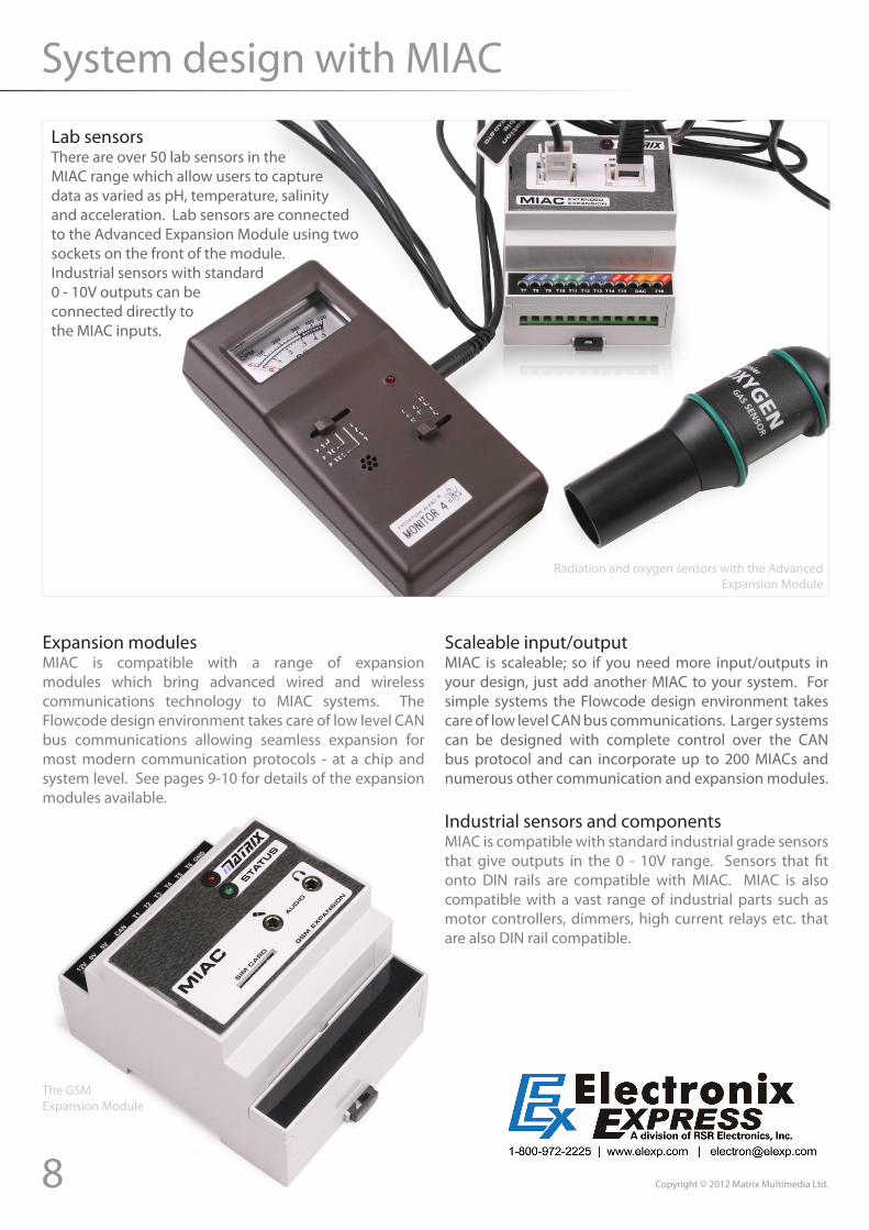
Lab sensorsThere are over 50 lab sensors in the MIAC range which allow users to capture data as varied as pH, temperature, salinity and acceleration. Lab sensors are connected to the Advanced Expansion Module using two sockets on the front of the module. Industrial sensors with standard 0 - 10V outputs can be connected directly to the MIAC inputs.
Scaleable input/outputMIAC is scaleable; so if you need more input/outputs in your design, just add another MIAC to your system. For simple systems the Flowcode design environment takes care of low level CAN bus communications. Larger systems can be designed with complete control over the CAN bus protocol and can incorporate up to 200 MIACs and numerous other communication and expansion modules.
Industrial sensors and componentsMIAC is compatible with standard industrial grade sensors that give outputs in the 0 - 10V range. Sensors that fit onto DIN rails are compatible with MIAC. MIAC is also compatible with a vast range of industrial parts such as motor controllers, dimmers, high current relays etc. that are also DIN rail compatible.
Radiation and oxygen sensors with the Advanced Expansion Module
Expansion modulesMIAC is compatible with a range of expansion modules which bring advanced wired and wireless communications technology to MIAC systems. The Flowcode design environment takes care of low level CAN bus communications allowing seamless expansion for most modern communication protocols - at a chip and system level. See pages 9-10 for details of the expansion modules available.
The GSM Expansion Module
9Copyright © 2012 Matrix Multimedia Ltd.
Expansion modules
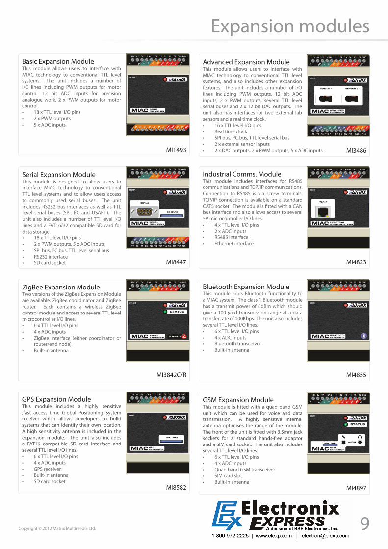
Basic Expansion ModuleThis module allows users to interface with MIAC technology to conventional TTL level systems. The unit includes a number of I/O lines including PWM outputs for motor control. 12 bit ADC inputs for precision analogue work, 2 x PWM outputs for motor control.• 18 x TTL level I/O pins• 2 x PWM outputs• 5 x ADC inputs
Advanced Expansion ModuleThis module allows users to interface with MIAC technology to conventional TTL level systems, and also includes other expansion features. The unit includes a number of I/O lines including PWM outputs, 12 bit ADC inputs, 2 x PWM outputs, several TTL level serial buses and 2 x 12 bit DAC outputs. The unit also has interfaces for two external lab sensors and a real time clock.• 16 x TTL level I/O pins• Real time clock• SPI bus, I2C bus, TTL level serial bus• 2 x external sensor inputs• 2 x DAC outputs, 2 x PWM outputs, 5 x ADC inputs
Serial Expansion ModuleThis module is designed to allow users to interface MIAC technology to conventional TTL level systems and to allow users access to commonly used serial buses. The unit includes RS232 bus interfaces as well as TTL level serial buses (SPI, I2C and USART). The unit also includes a number of TTl level I/O lines and a FAT16/32 compatible SD card for data storage.• 18 x TTL level I/O pins• 2 x PWM outputs, 5 x ADC inputs• SPI bus, I2C bus, TTL level serial bus• RS232 interface• SD card socket
Industrial Comms. ModuleThis module includes interfaces for RS485 communications and TCP/IP communications. Connection to RS485 is via screw terminals. TCP/IP connection is available on a standard CAT5 socket. The module is fitted with a CAN bus interface and also allows access to several 5V microcontroller I/O lines.• 4 x TTL level I/O pins• 2 x ADC inputs• RS485 interface• Ethernet interface
ZigBee Expansion ModuleTwo versions of the ZigBee Expansion Module are available: ZigBee coordinator and ZigBee router. Each contains a wireless ZigBee control module and access to several TTL level microcontroller I/O lines.• 6 x TTL level I/O pins• 4 x ADC inputs• ZigBee interface (either coordinator or
router/end node)• Built-in antenna
Bluetooth Expansion ModuleThis module adds Bluetooth functionality to a MIAC system. The class 1 Bluetooth module has a transmit power of 6dBm which should give a 100 yard transmission range at a data transfer rate of 100Kbps. The unit also includes several TTL level I/O lines.• 6 x TTL level I/O pins• 4 x ADC inputs• Bluetooth transceiver• Built-in antenna
GSM Expansion ModuleThis module is fitted with a quad band GSM unit which can be used for voice and data transmission. A highly sensitive internal antenna optimises the range of the module. The front of the unit is fitted with 3.5mm jack sockets for a standard hands-free adaptor and a SIM card socket. The unit also includes several TTL level I/O lines.• 6 x TTL level I/O pins• 4 x ADC inputs• Quad band GSM transceiver• SIM card slot• Built-in antenna
MI3842C/R
MI8447
MI1493 MI3486
MI4823
MI4855
MI4897MI8582
GPS Expansion ModuleThis module includes a highly sensitive ,fast access time Global Positioning System receiver which allows developers to build systems that can identify their own location. A high sensitivity antenna is included in the expansion module. The unit also includes a FAT16 compatible SD card interface and several TTL level I/O lines.• 6 x TTL level I/O pins• 4 x ADC inputs• GPS receiver• Built-in antenna• SD card socket
10 Copyright © 2012 Matrix Multimedia Ltd.
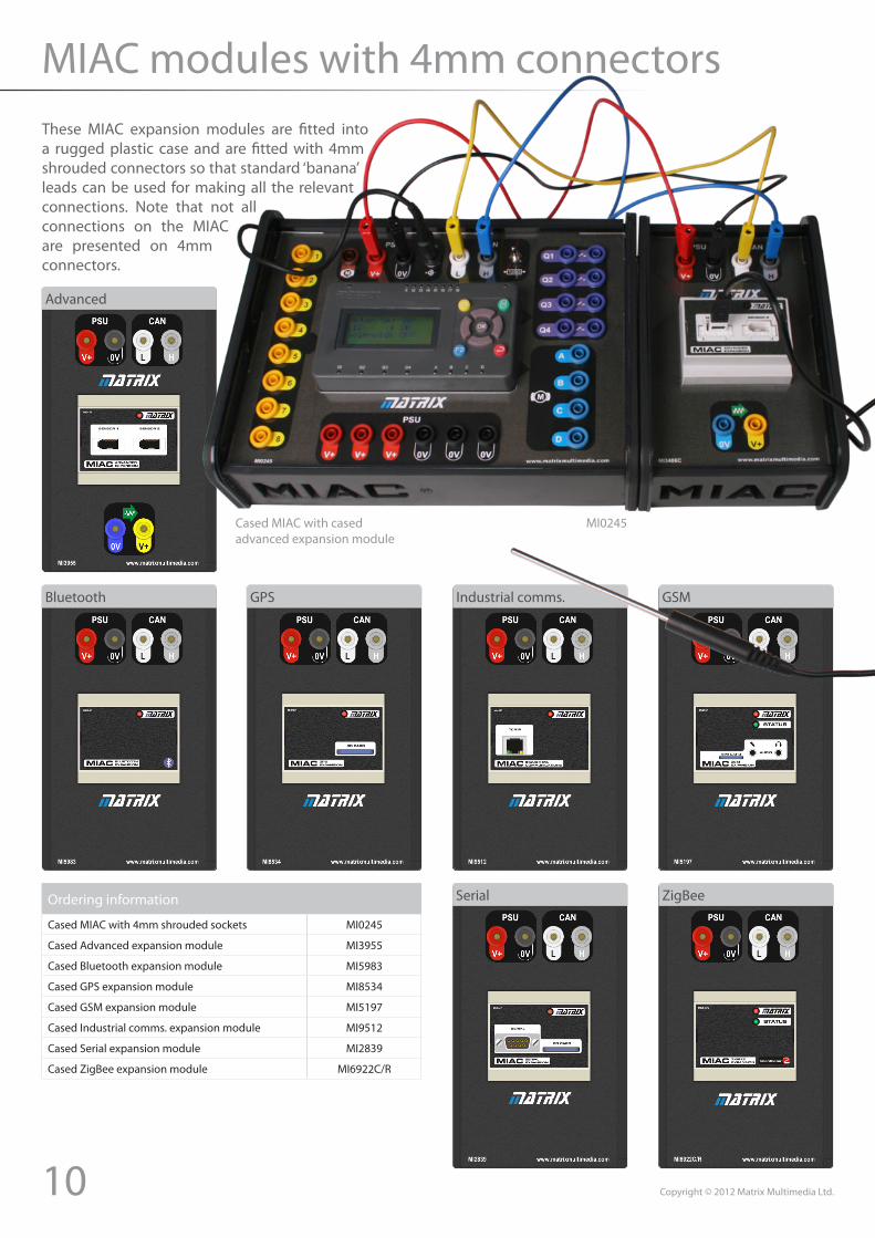
MIAC modules with 4mm connectorsThese MIAC expansion modules are fitted into a rugged plastic case and are fitted with 4mm shrouded connectors so that standard ‘banana’ leads can be used for making all the relevant connections. Note that not all connections on the MIAC are presented on 4mm connectors.
Ordering information
Cased MIAC with 4mm shrouded sockets MI0245
Cased Advanced expansion module MI3955
Cased Bluetooth expansion module MI5983
Cased GPS expansion module MI8534
Cased GSM expansion module MI5197
Cased Industrial comms. expansion module MI9512
Cased Serial expansion module MI2839
Cased ZigBee expansion module MI6922C/R
Advanced
Bluetooth GPS GSMIndustrial comms.
Serial ZigBee
Cased MIAC with cased advanced expansion module
MI0245
11Copyright © 2012 Matrix Multimedia Ltd.
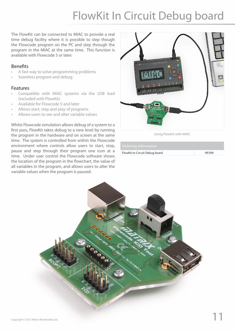
FlowKit In Circuit Debug boardThe FlowKit can be connected to MIAC to provide a real time debug facility where it is possible to step though the Flowcode program on the PC and step through the program in the MIAC at the same time. This function is available with Flowcode 5 or later.
Benefits• A fast way to solve programming problems• Seamless program and debug
Features• Compatible with MIAC systems via the USB lead
(included with FlowKit)• Available for Flowcode 5 and later• Allows start, step and play of programs• Allows users to see and alter variable values
Whilst Flowcode simulation allows debug of a system to a first pass, FlowKit takes debug to a new level by running the program in the hardware and on screen at the same time. The system is controlled from within the Flowcode environment where controls allow users to start, stop, pause and step through their program one icon at a time. Under user control the Flowcode software shows the location of the program in the flowchart, the value of all variables in the program, and allows users to alter the variable values when the program is paused.
Using FlowKit with MIAC
Ordering information
FlowKit In-Circuit Debug board HP299

12 Copyright © 2012 Matrix Multimedia Ltd.
Lab sensors
High currentUVA/B Soil moisture CO2 gas Colourimeter
Conductivity Radiation Differential voltage Dissolved oxygen Photogate
EKG sensor Current Force plate Flow rate Gas pressure
Hand dynamometer Force Heart rate - wearable Instrumentation Ion sensitive electrodes
Magnetic field Heart rate - hand grip Motion detector Oxygen pH
Microphone Relative humidity Respiration Rotary motion sensor Salinity
Spirometer Temperature Turbidity
HSCRG HSORP
+/- 5g+/- 25g3 axis +/- 5g HSBAR HSBPS
HSUVAHSSMS HSHCS HSCO2 HSCOL
HSCON HSDRM HSDVP HSDO HSVPG
HSEKG HSDCP HSFP HSFLO HSGPS
HSHD HSDFS HSEHR HSINA
HSMG HSHGH HSMD HSO2 HSPH
HSMCA HSRH HSRMB HSRMS HSSAL
HSSPR HSTMP HSTRB
HSUVB
HSLGAHSAAC
HS3D
CalciumChlorideAmmoniumNitrate
HSCAHSCL
HSNH4HSNO3
The MIAC Advanced Expansion module has two Left Hand Analogue sockets to enable the connection of a wide range of Vernier™ Lab Sensors.
Both sockets accept analogue voltage (0-5v), pulse and resistive
Charge Oxidation reduction Accelerometer Barometer Blood pressure
sensor types, such as Force Plates, Heart Rate Monitors and Temperature Probes.
Please note that they do not support the digital interface based sensors that use the Right Hand Digital type connectors.
13Copyright © 2012 Matrix Multimedia Ltd.
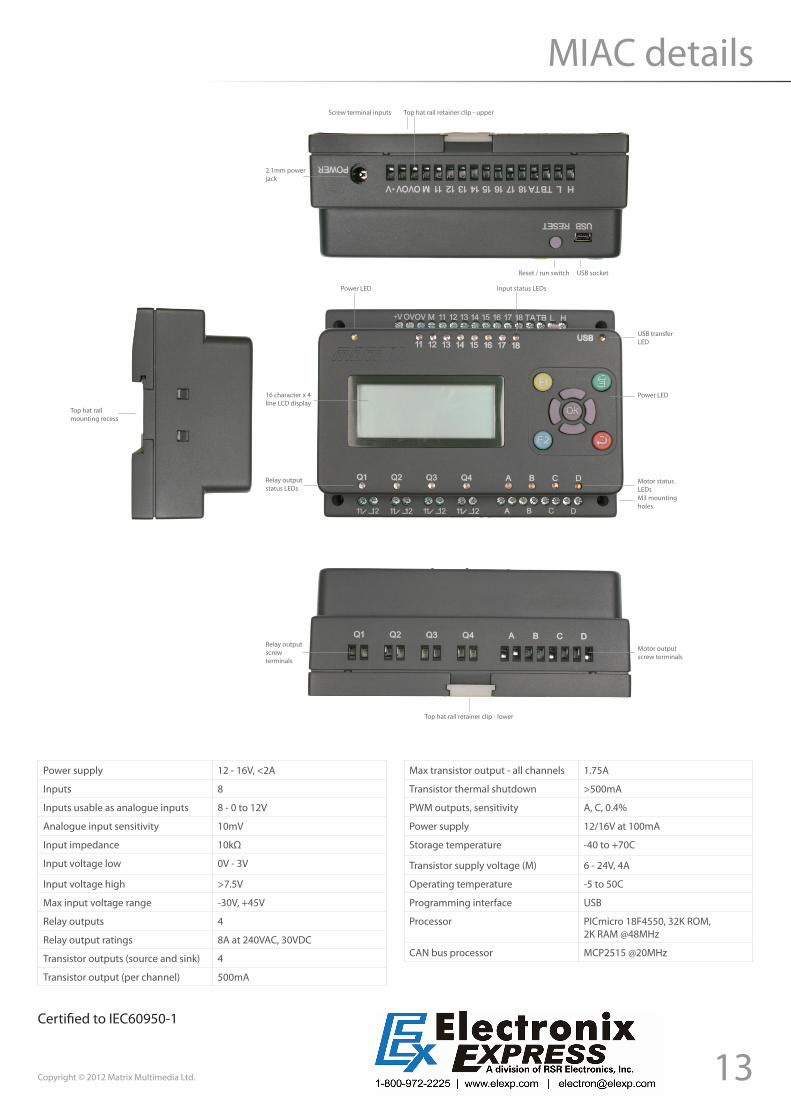
MIAC details
Power LED Input status LEDs
USB transferLED
Power LED
Motor statusLEDsM3 mountingholes
Relay outputstatus LEDs
16 character x 4line LCD display
Screw terminal inputs Top hat rail retainer clip - upper
USB socketReset / run switch
2.1mm powerjack
Top hat rail retainer clip - lower
Motor output screw terminals
Relay output screw terminals
Top hat rail mounting recess
Power supply 12 - 16V, <2A
Inputs 8
Inputs usable as analogue inputs 8 - 0 to 12V
Analogue input sensitivity 10mV
Input impedance 10kΩ
Input voltage low 0V - 3V
Input voltage high >7.5V
Max input voltage range -30V, +45V
Relay outputs 4
Relay output ratings 8A at 240VAC, 30VDC
Transistor outputs (source and sink) 4
Transistor output (per channel) 500mA
Max transistor output - all channels 1.75A
Transistor thermal shutdown >500mA
PWM outputs, sensitivity A, C, 0.4%
Power supply 12/16V at 100mA
Storage temperature -40 to +70C
Transistor supply voltage (M) 6 - 24V, 4A
Operating temperature -5 to 50C
Programming interface USB
Processor PICmicro 18F4550, 32K ROM,2K RAM @48MHz
CAN bus processor MCP2515 @20MHz
Certified to IEC60950-1


