E1963A W-CDMA Mobile Test Application For the E5515C/E (8960) wireless communications test set Technical Overview Accelerate UMTS test plan development and get your devices to market sooner, while ensuring compliance with TS 34.121-1 test standards. The Agilent Technologies E1963A W-CDMA mobile test application, when used with the Agilent GSM, GPRS, and EGPRS applications, is the industry standard for universal mobile telecommunications (UMTS) mobile test. Agilent’s 8960 (E5515C/E) test set provides you with a single hardware platform that covers all the UMTS/3GPP (Third Generation Partnership Project) radio formats: W-CDMA, HSPA, GSM, GPRS, EGPRS, and TD-SCDMA. Exceed your calibration test time goals with the E1999A-202 fast device tune measurement. Simultaneously calibrate your device’s transmitter (Tx) output power and receiver (Rx) input level across level and frequency. E1999A-202 is a superset of the discontinued E1999A-201. It not only offers the equivalent capabilities of the E1999A-201, it is enhanced to reduce the calibration test times for W-CDMA, cdma2000 ® , and 1xEV-DO wireless devices with smaller step size support (10 ms step size versus 20 ms step size). Reach your high-volume production goals by moving prototypes quickly into production with this test solution’s fast and repeatable measurements, accurate characterization, and ease of programming. The HSPA, W-CDMA, GSM, GPRS, and EGPRS product combination delivers a complete and integrated UMTS test solution in a single box. FM radio source, a single channel GPS source (E1999A-206), and PESQ measurement (E1999A-301) are also added into the test box for FM radio receiver calibration, GPS receiver calibration, and audio quality test without the need for an external audio analyzer. This fast, one-box approach simplifies your production process and increases your production line effectiveness. With the most complete test functionality for 3GPP TS 34.121-1 Section 5 and 6 tests, E1963A HSPA Options 403, 405, 413, 423, 433, and 435 provide fast, flexible measurements and options in user equipment (UE) connectivity, giving design and manufacturing test engineers more flexibility in creating test plans and the assur- ance that designs meet technology standards. Option 433 provides you with the functionality to test 42 Mbps downlink dual carrier (DC-HSDPA) and dual band dual carrier HSDPA (DB-DC-HSDPA) throughput in RB test mode and FDD test mode connection, and Option 435 allows validation of single and dual stream MIMO using 16QAM for a maximum data rate of 28 Mbps or 64QAM for 42 Mbps in RB test mode and FDD test mode connection.
Transcript
E1963A W-CDMA Mobile Test ApplicationFor the E5515CE (8960) wireless communications test set
Technical Overview
Accelerate UMTS test plan development and get your devices to market sooner while ensuring compliance with TS 34121-1 test standards The Agilent Technologies E1963A W-CDMA mobile test application when used with the Agilent GSM GPRS and EGPRS applications is the industry standard for universal mobile telecommunications (UMTS) mobile test Agilentrsquos 8960 (E5515CE) test set provides you with a single hardware platform that covers all the UMTS3GPP (Third Generation Partnership Project) radio formats W-CDMA HSPA GSM GPRS EGPRS and TD-SCDMA
Exceed your calibration test time goals with the E1999A-202 fast device tune measurement Simultaneously calibrate your devicersquos transmitter (Tx) output power and receiver (Rx) input level across level and frequency E1999A-202 is a superset of the discontinued E1999A-201 It not only offers the equivalent capabilities of the E1999A-201 it is enhanced to reduce the calibration test times for W-CDMA cdma2000reg and 1xEV-DO wireless devices with smaller step size support (10 ms step size versus 20 ms step size)
Reach your high-volume production goals by moving prototypes quickly into production with this test solutionrsquos fast and repeatable measurements accurate characterization and ease of programming
The HSPA W-CDMA GSM GPRS and EGPRS product combination delivers a complete and integrated UMTS test solution in a single box FM radio source a single channel GPS source (E1999A-206) and PESQ measurement (E1999A-301) are also added into the test box for FM radio receiver calibration GPS receiver calibration and audio quality test without the need for an external audio analyzer This fast one-box approach simplifies your production process and increases your production line effectiveness
With the most complete test functionality for 3GPP TS 34121-1 Section 5 and 6 tests E1963A HSPA Options 403 405 413 423 433 and 435 provide fast flexible measurements and options in user equipment (UE) connectivity giving design and manufacturing test engineers more flexibility in creating test plans and the assur-ance that designs meet technology standards Option 433 provides you with the functionality to test 42 Mbps downlink dual carrier (DC-HSDPA) and dual band dual carrier HSDPA (DB-DC-HSDPA) throughput in RB test mode and FDD test mode connection and Option 435 allows validation of single and dual stream MIMO using 16QAM for a maximum data rate of 28 Mbps or 64QAM for 42 Mbps in RB test mode and FDD test mode connection
2
Key Capabilities bull CSvoicehandoversbetweenGSMandW-CDMAontwotestsetsbull Fast device calibration across level and frequency simultaneouslybull Test HSDPA MIMO devices (HS-DSCH categories 15-20) as defined in 3GPP TS 34121-1 bull Test devices that support downlink dual carrier and dual band dual carrier (HS-DSCH categories 20-24) bull TestHSPAdevices(HS-DSCHcategories1-1417-18andE-DCH categories1-7)asdefinedin3GPPTS34121-1bull SwitchbetweenHSPAsub-testconditionswhileonanactive connection bull TestallUMTStechnologieswithoneconnectionmaintained throughout bull TestallfrequencybandsIthroughXIVXIXXXandXXIbull FMandGPSreceivercalibrationinoneboxbull TestvocoderspeechqualityusingtheindustrystandardPESQ algorithm
Tx measurements W-CDMA HSDPA HSUPA Thermal power Yes Yes Yes Channel power Yes Yes Yes Adjacent channel leakage ratio Yes Yes Yes Waveform quality Yes Yes Yes Spectrum emission mask Yes Yes Yes Phase discontinuity Yes Yes Yes Inner loop power Yes Occupied bandwidth Yes Yes Yes Code domain power Yes Yes Yes IQ constellation Yes Yes Yes Tx onoff power Yes Yes Yes Frequency stability Yes Yes Yes Dynamic power analysis Yes Yes Yes Tx dynamic power Yes Spectrum monitor Yes Yes Yes Rx measurements W-CDMA HSDPA HSUPA Loopback BER Yes NA NA BLER on DPCH (W-CDMA) Yes NA NA HBLER on HS-DPCCH (HSDPA) NA Yes NA
3
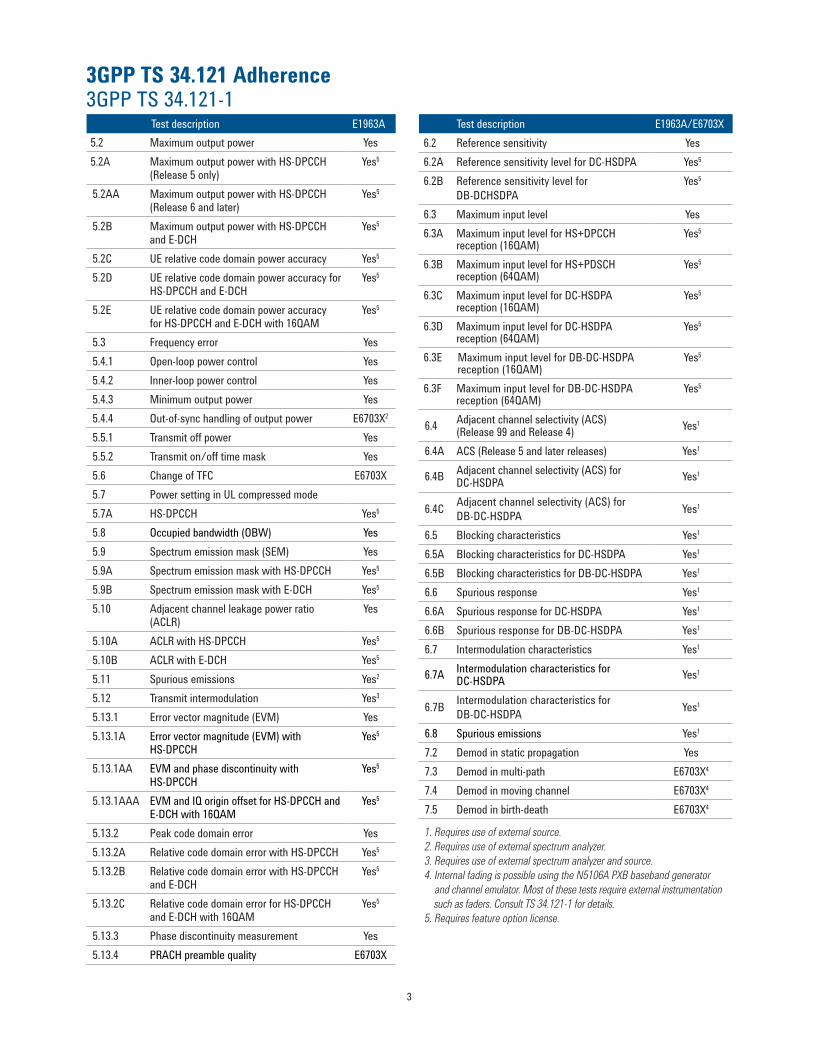
3GPP TS 34121 Adherence 3GPP TS 34121-1
Test description E1963A52 Maximum output power Yes 52A Maximum output power with HS-DPCCH
(Release 5 only)Yes5
52AA Maximum output power with HS-DPCCH(Release 6 and later)
Yes5
52B Maximum output power with HS-DPCCH and E-DCH
Yes5
52C UE relative code domain power accuracy Yes5
52D UE relative code domain power accuracy forHS-DPCCH and E-DCH
Yes5
52E UE relative code domain power accuracyfor HS-DPCCH and E-DCH with 16QAM
Yes5
53 Frequency error Yes 541 Open-loop power control Yes 542 Inner-loop power control Yes 543 Minimum output power Yes 544 Out-of-sync handling of output power E6703X2
551 Transmit off power Yes552 Transmit onoff time mask Yes 56 Change of TFC E6703X57 Power setting in UL compressed mode57A HS-DPCCH Yes5 58 Occupied bandwidth (OBW) Yes59 Spectrum emission mask (SEM) Yes 59A Spectrum emission mask with HS-DPCCH Yes5 59B Spectrum emission mask with E-DCH Yes5
64B Adjacent channel selectivity (ACS) for DC-HSDPA Yes1
64C Adjacent channel selectivity (ACS) for DB-DC-HSDPA Yes1
65 Blocking characteristics Yes1
65A Blocking characteristics for DC-HSDPA Yes1
65B Blocking characteristics for DB-DC-HSDPA Yes1
66 Spurious response Yes1
66A Spurious response for DC-HSDPA Yes1
66B Spurious response for DB-DC-HSDPA Yes1
67 Intermodulation characteristics Yes1
67A Intermodulation characteristics for DC-HSDPA Yes1
67B Intermodulation characteristics for DB-DC-HSDPA Yes1
68 Spurious emissions Yes1
72 Demod in static propagation Yes73 Demod in multi-path E6703X4
74 Demod in moving channel E6703X4
75 Demod in birth-death E6703X4
1 Requires use of external source 2 Requires use of external spectrum analyzer 3 Requires use of external spectrum analyzer and source 4 Internal fading is possible using the N5106A PXB baseband generator and channel emulator Most of these tests require external instrumentation such as faders Consult TS 34121-1 for details5 Requires feature option license
4
Related Literature Technical Specifications The Most Complete Test Functionality for HSPAW-CDMA Wireless Devices photocard(5989-3414EN)Agilent 8960 Wireless Communications Test Set HSPA Applications photocard 5989-7515EN 8960 Series 10 Wireless Communications Test Set configuration guide 5968-7873E
For More Information Learn more about the E1963A test application and HSPA options at wwwagilentcomfindE1963A
Technical Specifications These specifications apply to an E5515CE mainframe with Option 003 when used with the latest E1963A test application ortheE1987Atestapplication
Specifications describe the test setrsquos warranted performance and are valid for the unitrsquos operation within the stated environmental ranges unless otherwise noted All specifications are valid after a 30-minute warm-up period of continuous operation
Supplemental characteristics are intended to provide typical but non-warranted performance parameters that may be useful in apply-ing the instrument These characteristics are shown in italics and labeled as ldquotypicalrdquo All units shipped from the factory meet these typical numbers at +25 degC ambient temperature without including measurement uncertainty
What is Included in This Technical Overview This data sheet is organized in four sections bull HSPAspecificationsbull W-CDMAspecificationsbull HSPAandW-CDMAcommontechnicalspecificationsbull Generalspecifications
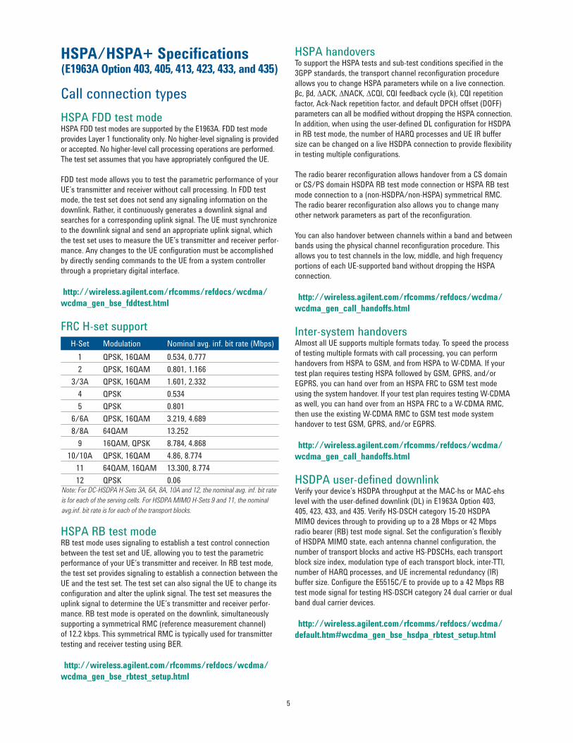
Call connection types HSPA FDD test mode HSPA FDD test modes are supported by the E1963A FDD test mode provides Layer 1 functionality only No higher-level signaling is provided or accepted No higher-level call processing operations are performed The test set assumes that you have appropriately configured the UE
FDD test mode allows you to test the parametric performance of your UErsquos transmitter and receiver without call processing In FDD test mode the test set does not send any signaling information on the downlink Rather it continuously generates a downlink signal and searches for a corresponding uplink signal The UE must synchronize to the downlink signal and send an appropriate uplink signal which the test set uses to measure the UErsquos transmitter and receiver perfor-mance Any changes to the UE configuration must be accomplished by directly sending commands to the UE from a system controller through a proprietary digital interface
FRC H-set support H-Set Modulation Nominal avg inf bit rate (Mbps)
1 QPSK 16QAM 053407772 QPSK 16QAM 0801 1166
33A QPSK 16QAM 1601 2332 4 QPSK 0534 5 QPSK 0801
66A QPSK 16QAM 3219 4689 88A 64QAM 13252
9 16QAM QPSK 878448681010A QPSK 16QAM 4868774
11 64QAM 16QAM 13300877412 QPSK 006
Note For DC-HSDPA H-Sets 3A 6A 8A 10A and 12 the nominal avg inf bit rateis for each of the serving cells For HSDPA MIMO H-Sets 9 and 11 the nominalavginf bit rate is for each of the transport blocks
HSPA RB test mode RB test mode uses signaling to establish a test control connection between the test set and UE allowing you to test the parametric performance of your UErsquos transmitter and receiver In RB test mode the test set provides signaling to establish a connection between the UE and the test set The test set can also signal the UE to change its configuration and alter the uplink signal The test set measures the uplink signal to determine the UErsquos transmitter and receiver perfor-mance RB test mode is operated on the downlink simultaneously supporting a symmetrical RMC (reference measurement channel) of 122 kbps This symmetrical RMC is typically used for transmitter testing and receiver testing using BER
HSPA handovers To support the HSPA tests and sub-test conditions specified in the 3GPP standards the transport channel reconfiguration procedure allows you to change HSPA parameters while on a live connection βc βd ∆ACK ∆NACK ∆CQI CQI feedback cycle (k) CQI repetition factor Ack-Nack repetition factor and default DPCH offset (DOFF) parameters can all be modified without dropping the HSPA connection In addition when using the user-defined DL configuration for HSDPA in RB test mode the number of HARQ processes and UE IR buffer size can be changed on a live HSDPA connection to provide flexibility in testing multiple configurations
The radio bearer reconfiguration allows handover from a CS domain or CSPS domain HSDPA RB test mode connection or HSPA RB test mode connection to a (non-HSDPAnon-HSPA) symmetrical RMC The radio bearer reconfiguration also allows you to change many other network parameters as part of the reconfiguration
You can also handover between channels within a band and between bands using the physical channel reconfiguration procedure This allows you to test channels in the low middle and high frequency portions of each UE-supported band without dropping the HSPA connection
Inter-system handovers Almost all UE supports multiple formats today To speed the process of testing multiple formats with call processing you can perform handovers from HSPA to GSM and from HSPA to W-CDMA If your test plan requires testing HSPA followed by GSM GPRS andor EGPRS you can hand over from an HSPA FRC to GSM test mode using the system handover If your test plan requires testing W-CDMA as well you can hand over from an HSPA FRC to a W-CDMA RMC then use the existing W-CDMA RMC to GSM test mode system handover to test GSM GPRS andor EGPRS
HSDPA user-defined downlink Verify your devicersquos HSDPA throughput at the MAC-hs or MAC-ehs level with the user-defined downlink (DL) in E1963A Option 403 405 423 433 and 435 Verify HS-DSCH category 15-20 HSDPA MIMO devices through to providing up to a 28 Mbps or 42 Mbps radio bearer (RB) test mode signal Set the configurationrsquos flexibly of HSDPA MIMO state each antenna channel configuration the number of transport blocks and active HS-PDSCHs each transport block size index modulation type of each transport block inter-TTI number of HARQ processes and UE incremental redundancy (IR) buffer size Configure the E5515CE to provide up to a 42 Mbps RB test mode signal for testing HS-DSCH category 24 dual carrier or dual band dual carrier devices
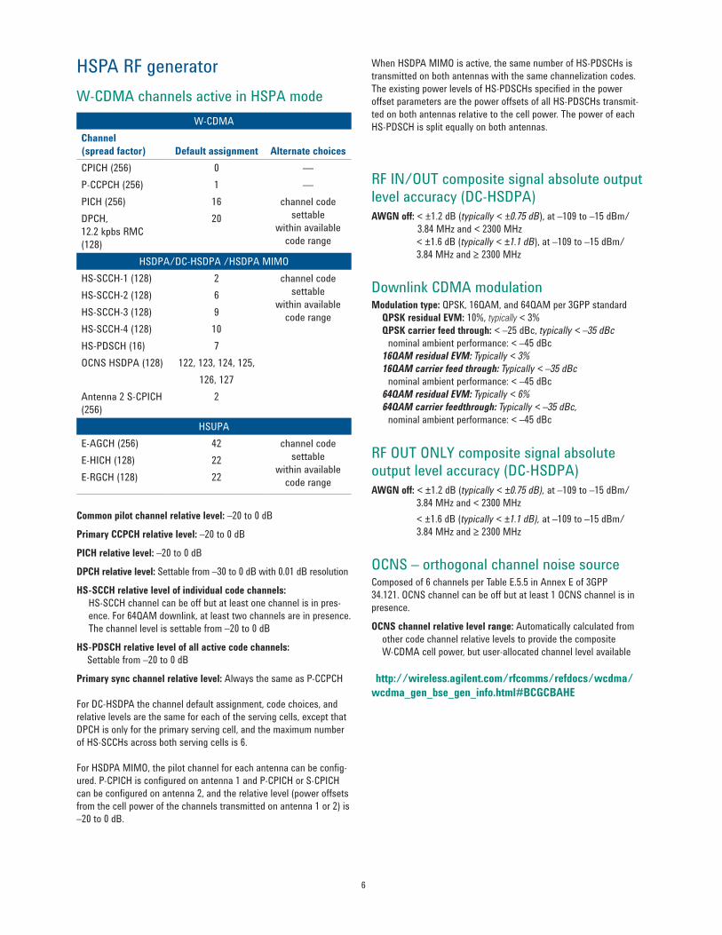
Common pilot channel relative level ndash20 to 0 dB
Primary CCPCH relative level ndash20 to 0 dB
PICH relative level ndash20 to 0 dB
DPCH relative level Settable from ndash30 to 0 dB with 001 dB resolution
HS-SCCH relative level of individual code channels HS-SCCH channel can be off but at least one channel is in pres-ence For 64QAM downlink at least two channels are in presence The channel level is settable from ndash20 to 0 dB
HS-PDSCH relative level of all active code channels Settable from ndash20 to 0 dB
Primary sync channel relative level Always the same as P-CCPCH
For DC-HSDPA the channel default assignment code choices and relative levels are the same for each of the serving cells except that DPCH is only for the primary serving cell and the maximum number of HS-SCCHs across both serving cells is 6
For HSDPA MIMO the pilot channel for each antenna can be config-ured P-CPICH is configured on antenna 1 and P-CPICH or S-CPICH can be configured on antenna 2 and the relative level (power offsets from the cell power of the channels transmitted on antenna 1 or 2) is ndash20 to 0 dB
When HSDPA MIMO is active the same number of HS-PDSCHs is transmitted on both antennas with the same channelization codes The existing power levels of HS-PDSCHs specified in the power offset parameters are the power offsets of all HS-PDSCHs transmit-ted on both antennas relative to the cell power The power of each HS-PDSCH is split equally on both antennas
RF INOUT composite signal absolute output level accuracy (DC-HSDPA) AWGN off lt plusmn12 dB (typically lt plusmn075 dB) at ndash109 to ndash15 dBm
384 MHz and lt 2300 MHz lt plusmn16 dB (typically lt plusmn11 dB) at ndash109 to ndash15 dBm 384 MHz and ge 2300 MHz
Downlink CDMA modulation Modulation type QPSK 16QAM and 64QAM per 3GPP standard QPSK residual EVM 10 typically lt 3 QPSK carrier feed through lt ndash25 dBc typically lt ndash35 dBc nominal ambient performance lt ndash45 dBc 16QAM residual EVM Typically lt 3 16QAM carrier feed through Typically lt ndash35 dBc nominal ambient performance lt ndash45 dBc 64QAM residual EVM Typically lt 6 64QAM carrier feedthrough Typically lt ndash35 dBc nominal ambient performance lt ndash45 dBc
RF OUT ONLY composite signal absolute output level accuracy (DC-HSDPA) AWGN off lt plusmn12 dB (typically lt plusmn075 dB) at ndash109 to ndash15 dBm 384 MHz and lt 2300 MHz lt plusmn16 dB (typically lt plusmn11 dB) at ndash109 to ndash15 dBm 384 MHz and ge 2300 MHz OCNS ndash orthogonal channel noise source Composed of 6 channels per Table E55 in Annex E of 3GPP 34121 OCNS channel can be off but at least 1 OCNS channel is in presence
OCNS channel relative level range Automatically calculated from other code channel relative levels to provide the composite W-CDMA cell power but user-allocated channel level available (httpwirelessagilentcomrfcommsrefdocswcdmawcdma_gen_bse_gen_infohtmlBCGCBAHE)
Tx measurements Channel power measurementInput signal modulation QPSK and 16QAM
Measurement bandwidth RRC filter off Measured with a bandwidth greater than (1 + α) x chip rate where α = 022 and chip rate = 384 Mcps RRC filter on Measured with a filter that has a root-raised cosine (RRC) filter response with roll-off α = 022 and a bandwidth equal to the chip rate 384 MHz centered on the active uplink channel)
Measurement range ndash61 to +28 dBm384 MHz
Measurement interval Settable from 001 to 12 ms
Measurement accuracy (at plusmn10 degC from the calibration temperature) lt plusmn10 dB (typically lt plusmn05 dB) for measurement intervals of 333 micros to 12 ms over 698 to 1024 MHz 1400 to 1500 MHz and 1700to2000MHz lt plusmn10 dB (typically lt plusmn055 dB) for measurement intervals of 333 micros to 12 ms over 2480 to 2580 MHz lt plusmn10 dB (typically lt plusmn06 dB) for measurement intervals of 67tolt333microsover698to1024MHz1400to1500MHzand 1700to2000MHz
Measurement triggers Auto immediate protocol RF rise external and HS-DPCCH
Phase discontinuity Measurement method The measured results include the phase discontinuity (defined as the phase difference of adjacent timeslots) as well as all waveform quality results for each timeslot
Input power level range Phase discontinuity ndash61 to +28 dBm384 MHz Other measurements ndash25 to +28 dBm384 MHz
Input frequency ranges800to1000MHz1700to1990MHz
Phase discontinuity range plusmn180deg
EVM range 0 to 35 rms
Phase discontinuity measurement accuracy lt plusmn24deg (typically lt plusmn17deg) for input levels of ndash25 to +28 dBm384 MHz lt plusmn26deg (typically lt plusmn19deg) for input levels of ndash51 to lt ndash25 dBm384 MHz
Other reported parameters with phase discontinuity All measurements found in the waveform quality measurement are also available the specifications are the same in both measurements including the input power range of the waveform quality measurement
Measurement interval 617micros(=1timeslot(667micros)ndash25micros transient periods at either side of the nominal timeslot boundaries) or 283 micros (05 timeslot (333 micros) ndash 25 micros transient periods at either side of the nominal timeslot boundaries)
Measurement triggers Protocol external and HS-DPCCH
Temperature range +20 to +55 degC
Concurrency capabilities Phase discontinuity measurements cannot be made concurrently with other measurements
Measurement interval 05 to 10 timeslot with choice to include or exclude 25 micros transient periods
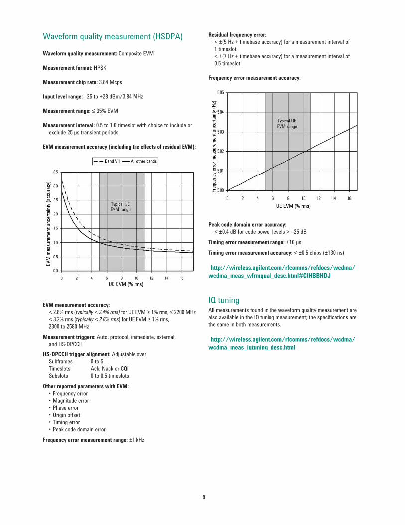
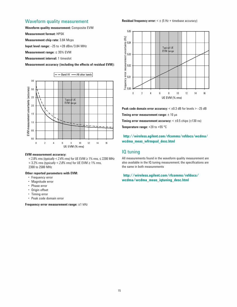
EVM measurement accuracy (including the effects of residual EVM)
EVM measurement accuracy lt 28 rms (typically lt 24 rms) for UE EVM ge 1 rms le 2200 MHz lt 32 rms (typically lt 28 rms) for UE EVM ge 1 rms 2300 to 2580 MHz
Measurement triggers Auto protocol immediate external and HS-DPCCH
HS-DPCCH trigger alignment Adjustable over Subframes 0 to 5 Timeslots Ack Nack or CQI Subslots 0 to 05 timeslots
Other reported parameters with EVM bullFrequencyerrorbullMagnitudeerrorbullPhaseerrorbullOriginoffsetbullTimingerrorbullPeakcodedomainerror
Frequency error measurement range plusmn1 kHz
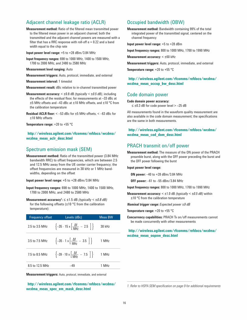
Residual frequency error lt plusmn(5 Hz + timebase accuracy) for a measurement interval of 1 timeslot ltplusmn(7Hz+timebaseaccuracy)forameasurementintervalof 05 timeslot
Frequency error measurement accuracy
Peak code domain error accuracy lt plusmn04 dB for code power levels gt ndash25 dB
IQ tuning All measurements found in the waveform quality measurement are also available in the IQ tuning measurement the specifications are the same in both measurements
Dynamic power analysis Measurement method Graphical display of the uplink power waveform including HS-DPCCH DPCH versus time by using the HS-DPCCH trigger source results will be aligned to the HS-DPCCH
Input power level range ndash61 to +28 dBm384 MHz
Measurement level ranging Auto
Data capture range Combination of number of steps and step length cannot exceed 5826 ms
Measurement bandwidth Selectable RRC filter on or off
Measurement interval Settable from 001 to 12 ms (must be less than or equal to the step length)
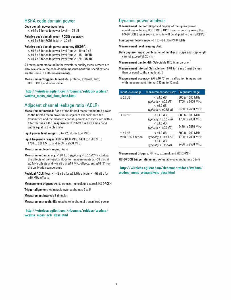
Measurement accuracy (At plusmn10 degC from calibration temperature with measurement interval 333 micros to 12 ms)
Input level range Measurement accuracy Frequency rangele 25 dB lt plusmn10 dB
typically lt plusmn05 dB lt plusmn10 dB
typically lt plusmn055 dB
800 to 1000 MHz 1700to2000MHz
2480 to 2580 MHz
le 35 dB lt plusmn10 dB typically lt plusmn055 dB
lt plusmn10 dB typically lt plusmn06 dB
800 to 1000 MHz1700to2000MHz 2480 to 2580 MHz
le 40 dB with RRC filter on
lt plusmn10 dB typically lt plusmn055 dB
lt plusmn10 dB typically lt plusmn07 dB
800 to 1000 MHz 1700to2000MHz 2480 to 2580 MHz
Measurement triggers RF rise external and HS-DPCCH
HS-DPCCH trigger alignment Adjustable over subframes 0 to 5 (httpwirelessagilentcomrfcommsrefdocswcdmawcdma_meas_wdpanalysis_deschtml)
HSPA code domain power Code domain power accuracy lt plusmn04 dB for code power level gt ndash25 dB
Relative code domain error (RCDE) accuracy le plusmn05 dB for RCDE level gt ndash20 dB
Relative code domain power accuracy (RCDPA) le plusmn02 dB for code power level from ge ndash10 to 0 dB le plusmn03 dB for code power level from ge ndash15 ndash10 dB le plusmn04 dB for code power level from ge ndash20 ndash15 dB
All measurements found in the waveform quality measurement are also available in the code domain measurement the specifications are the same in both measurements
Measurement triggers Immediate protocol external auto HS-DPCCH and even frame
Adjacent channel leakage ratio (ACLR) Measurement method Ratio of the filtered mean transmitted power to the filtered mean power in an adjacent channel both the transmitted and the adjacent channel powers are measured with a filter that has a RRC response with roll-off α = 022 and a band width equal to the chip rate
Input power level range +5 to +28 dBm384 MHz
Input frequency ranges 698 to 1000 MHz 1400 to 1500 MHz 1700to2000MHzand2480to2580MHz
Measurement level ranging Auto
Measurement accuracy lt plusmn08 dB (typically lt plusmn05 dB) including the effects of the residual floor for measurements at ndash33 dBc at plusmn5 MHz offsets and ndash43 dBc at plusmn10 MHz offsets and plusmn10 degC from the calibration temperature
Residual ACLR floor lt ndash48 dBc for plusmn5 MHz offsets lt ndash58 dBc for plusmn10 MHz offsets
Measurement triggers Auto protocol immediate external HS-DPCCH
Trigger alignment Adjustable over subframes 0 to 5
Measurement interval 1 timeslot
Measurement result dBc relative to in-channel transmitted power
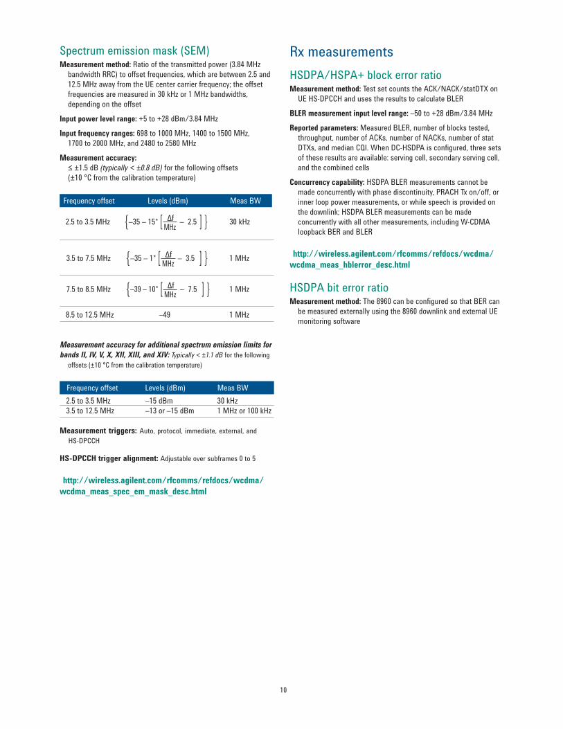
Rx measurements HSDPAHSPA+ block error ratio Measurement method TestsetcountstheACKNACKstatDTXon UE HS-DPCCH and uses the results to calculate BLER BLER measurement input level range ndash50 to +28 dBm384 MHz
Reported parameters Measured BLER number of blocks tested throughput number of ACKs number of NACKs number of stat DTXsandmedianCQIWhenDC-HSDPAisconfiguredthreesets of these results are available serving cell secondary serving cell and the combined cells
Concurrency capability HSDPA BLER measurements cannot be made concurrently with phase discontinuity PRACH Tx onoff or inner loop power measurements or while speech is provided on the downlink HSDPA BLER measurements can be made concurrently with all other measurements including W-CDMA loopback BER and BLER
HSDPA bit error ratio Measurement method The 8960 can be configured so that BER can be measured externally using the 8960 downlink and external UE monitoring software
Spectrum emission mask (SEM) Measurement method Ratio of the transmitted power (384 MHz bandwidth RRC) to offset frequencies which are between 25 and 125 MHz away from the UE center carrier frequency the offset frequencies are measured in 30 kHz or 1 MHz bandwidths depending on the offset
Input power level range +5 to +28 dBm384 MHz
Input frequency ranges 698 to 1000 MHz 1400 to 1500 MHz 1700to2000MHzand2480to2580MHz
Measurement accuracy le plusmn15 dB (typically lt plusmn08 dB) for the following offsets (plusmn10 degC from the calibration temperature) Frequency offset Levels (dBm) Meas BW
Measurement accuracy for additional spectrum emission limits for bands II IV V X XII XIII and XIV Typically lt plusmn11 dB for the following offsets (plusmn10 degC from the calibration temperature)
Frequency offset Levels (dBm) Meas BW 25 to 35 MHz ndash15 dBm 30 kHz 35 to 125 MHz ndash13 or ndash15 dBm 1 MHz or 100 kHz Measurement triggers Auto protocol immediate external and
HS-DPCCH
HS-DPCCH trigger alignment Adjustable over subframes 0 to 5
W-CDMA Specifications Call connection types End-to-end video conferencing (Option 401) Loop back video conferencing (Option 402) The E1963A when configured as a two-instrument system provides true H324 call setup with live video and audio from both mobile devices With only one E5515C loop back video call can be setup with Option 402
Validate compatibility by testing interoperability between your mobile and the competitor models offered for the same network
bull Complete call setup mobile origination and mobile release bull 64 k circuit-switched UDI channel bull H324 call setup
AMR voice Standard voice call with audio loopback for a quick check of voice functionalityfor122kratealsomanymoreAMRratessuchas475515596774795102and122k
bull UE and BS origination 122 k bull UE and BS release
FDD test mode FDD test mode allows you to test the parametric performance of your UErsquos transmitter and receiver without call processing In FDD test mode the test set does not send signaling information on the downlink Rather it continuously generates a downlink signal and searches for a corresponding uplink signal The UE must synchronize to the downlink signal and send and appropriate uplink signal which the test set uses to measure the UErsquos transmitter and receiver performance Any changes to the UE configuration must be accom-plished by directly sending commands to the UE from a system controller through a proprietary digital interface
RB test mode Fast conformance test calls with significant configuration control and testing capabilities
BS origination and release Symmetrical configuration W-CDMA modes support symmetrical RMCs at 122 64 144 and 384 k rates These symmetrical RMCs are typically used for transmitter testing and receiver testing user BER (via loopback type 1) or BLER (via loopback type 2) Asymmetric configuration The asymmetrical RMCs use either a 122 or a 64 k channel on the uplink The primary purpose of the symmetrical RMCs is to provide a way to make a BLER measurement by counting retransmission requests that the UE sends There is no need for data loopback in this mode
Inter-system handover Dual-mode functionality is required for most W-CDMA phones as GSM is an integral part in the majority of devices shipping today Inter-system handovers provide a means to validate dual-mode performance at your desk instead of roaming on a real network When operated in conjunction with compressed mode this feature can very closely emulate the basics of a real handover as made on the network
bull Blind handovers from W-CDMA to GSM bull Configurable landing GSM cell bull Test control to GSM voice bull W-CDMA AMR voice to GSM voice
Spreading factor of 128 at the fixed OVSF codes of 2 1117233138475562697885 94 113 119
125
Channel code is settable within
available code range
RF generator level accuracy is derived from the 99th percentile observations with 95 confidence (corresponds to an expanded uncertainty with a 95 confidence (k=2)) at ambient conditions then qualified to include the environmental effects of temperature and humidity
RF INOUT cell power absolute output level accuracy AWGN off lt plusmn11 dB (typically lt plusmn065 dB) at ndash109 to ndash15 dBm384 MHz and lt 2300 MHz lt plusmn15 dB (typically lt plusmn10 dB) at ndash109 to ndash15 dBm384 MHz and ge 2300 MHz
RF INOUT composite signal absolute output level accuracy AWGN on lt plusmn12 dB at ndash80 to ndash20 dBm384 MHz and lt 2300 MHz typically lt plusmn075 dB over ndash109 to ndash20 dBm384 MHz and lt 2300 MHz lt plusmn16 dB at ndash80 to ndash20 dBm384 MHz and ge 2300 MHz typically lt plusmn11 dB at ndash109 to ndash20 dBm384 MHz and ge 2300 MHz
RF OUT ONLY cell power absolute output level accuracyAWGN off lt plusmn11 dB at ndash109 to ndash7 dBm384 MHz and lt 2300 MHz typically lt plusmn065 dB ndash109 to ndash15 dBm384 MHz lt plusmn15 dB typically lt plusmn10 dB at ndash109 to ndash15 dBm384 MHz and ge 2300 MHz
RF OUT ONLY composite signal absolute output level accuracy AWGN on lt plusmn12 dB at ndash80 to ndash12 dBm384 MHz and lt 2300 MHz typically lt plusmn075 dB at ndash109 to ndash20 dBm384 MHz and lt 2300 MHz lt plusmn16 dB at ndash80 to ndash20 dBm384 MHz and ge 2300 MHz typically lt plusmn11 dB at ndash109 to ndash20 dBm384 MHz and ge 2300 MHz
Common pilot channel relative level ndash20 to 0 dB
Primary sync channel relative level Always the same as P-CCPCH
Secondary sync channel relative level Always the same as P-CCPCH
Primary CCPCH relative level ndash20 to 0 dB
DPCH relative level Settable from ndash30 to 0 dB with 001 dB resolution
PICH relative level ndash20 to 0 dB
Downlink CDMA modulation Modulation type QPSK per 3GPP standard Residual EVM lt 10 typically lt 3 Carrier feed through lt ndash25 dBc typically lt ndash35 dBc nominal ambient performance lt ndash45 dBc
OCNS ndash orthogonal channel noise source Composed of 16 channels per Table E36 in Annex E of 3GPP 34121
OCNS channel relative level range Automatically calculated from other code channel relative levels to provide the set CDMA cell power
Relative CDMA channel level accuracy lt plusmn02 dB (httpwirelessagilentcomrfcommsrefdocswcdmawcdma_gen_bse_gen_infohtmlBCGCBAHE)
13
W-CDMA RF analyzer (measurements only)
Real-time demodulation of Uplink DPCH
W-CDMA Tx measurements Thermal power measurement Measurement bandwidth gt 5 MHz if other signals are present outside of this frequency range reduced measurement accuracy will result
Measurement data capture period 10 ms
Measurement range ndash10 to +28 dBm usable to ndash20 dBm with degraded accuracy
Measurement level ranging Auto
Auto zero function Measurement automatically zeros the thermal power meter (no user control)
Channel power measurement Measurement bandwidth RRC filter off Measured with a bandwidth greater than (1 + α) x chip rate where α = 022 and chip rate = 384 Mcps RRC filter on Measured with a filter that has a root-raised cosine (RRC) filter response with roll-off α = 022 and a bandwidth equal to the chip rate (384 MHz bandwidth centered on the active uplink channel) Measurement range ndash61 to +28 dBm384 MHz
Measurement interval Settable from 001 to 12 ms
Measurement triggers Auto immediate protocol external and RF rise
Measurement accuracy (at +10 degC from the calibration temperature)
lt plusmn10 dB (typically lt plusmn05 dB) for measurement intervals of 333 micros to 12 ms over 698 to 1024 MHz 1400 to 1500 MHz and 1700to2000MHz lt plusmn10 dB (typically lt plusmn055 dB) for measurement intervals of 333 micros to 12 ms over 2480 to 2580 MHz lt plusmn10 dB (typically lt plusmn055 dB) for measurement intervals of 67tolt333microsover698to1024MHz1400to1500MHzand1700to2000MHz
Temperature range +20 to +55 degC
Temperature drift Typically 01 dB per 10 degC temperature change (httpwirelessagilentcomrfcommsrefdocswcdmawcdma_meas_chanpow_deschtml)
14
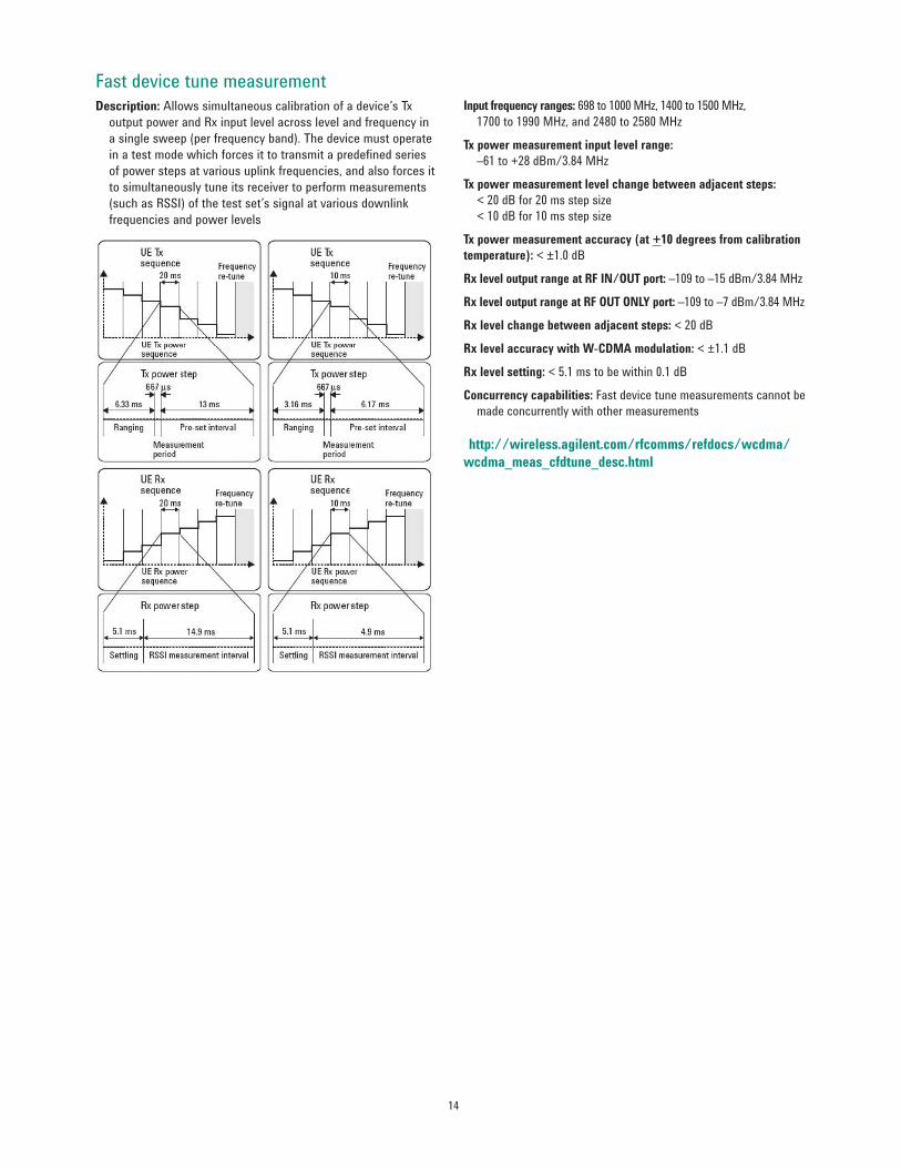
Fast device tune measurement Description Allows simultaneous calibration of a devicersquos Tx
output power and Rx input level across level and frequency in a single sweep (per frequency band) The device must operate in a test mode which forces it to transmit a predefined series of power steps at various uplink frequencies and also forces it to simultaneously tune its receiver to perform measurements (such as RSSI) of the test setrsquos signal at various downlink frequencies and power levels
Input frequency ranges 698 to 1000 MHz 1400 to 1500 MHz 1700to1990MHzand2480to2580MHz
Tx power measurement input level range ndash61 to +28 dBm384 MHz
Tx power measurement level change between adjacent steps lt 20 dB for 20 ms step size lt 10 dB for 10 ms step size
Tx power measurement accuracy (at +10 degrees from calibration temperature) lt plusmn10 dB
Rx level output range at RF INOUT port ndash109 to ndash15 dBm384 MHz
Rx level output range at RF OUT ONLY port ndash109tondash7dBm384MHz
Rx level change between adjacent steps lt 20 dB
Rx level accuracy with W-CDMA modulation lt plusmn11 dB
Rx level setting lt 51 ms to be within 01 dB
Concurrency capabilities Fast device tune measurements cannot be made concurrently with other measurements
IQ tuning All measurements found in the waveform quality measurement are also available in the IQ tuning measurement the specifications are the same in both measurements
Measurement accuracy (including the effects of residual EVM)
EVM measurement accuracy lt 28 rms (typically lt 24 rms) for UE EVM ge 1 rms le 2200 MHz lt 32 rms (typically lt 28 rms) for UE EVM ge 1 rms 2300 to 2580 MHz
Other reported parameters with EVM bull Frequency error bull Magnitude error bull Phase error bullOriginoffsetbull Timing error bull Peak code domain error
Frequency error measurement range plusmn1 kHz
16
Occupied bandwidth (OBW) Measurement method Bandwidth containing 99 of the total integrated power of the transmitted signal centered on the channel frequency
Input power level range +5 to +28 dBm
Input frequency ranges800to1000MHz1700to1990MHz
Measurement accuracy lt plusmn60 kHz
Measurement triggers Auto protocol immediate and external
Code domain power Code domain power accuracy le plusmn03 dB for code power level gt ndash25 dB
All measurements found in the waveform quality measurement are also available in the code domain measurement the specifications are the same in both measurements
PRACH transmit onoff power Measurement method The measure of the ON power of the PRACH preamble burst along with the OFF power preceding the burst and the OFF power following the burst
Input power level range
ON power ndash40 to +28 dBm384 MHz
OFF power ndash61 to ndash55 dBm384 MHz
Input frequency ranges800to1000MHz1700to1990MHz
Measurement accuracy lt plusmn10 dB (typically lt plusmn05 dB) within plusmn10 degC from the calibration temperature
Nominal trigger range Expected power plusmn9 dB
Temperature range +20 to +55 degC
Concurrency capabilities PRACH Tx onoff measurements cannot be made concurrently with other measurements
1 Refer to HSPA SEM specification on page 9 for additional requirements
Adjacent channel leakage ratio (ACLR) Measurement method Ratio of the filtered mean transmitted power to the filtered mean power in an adjacent channel both the transmitted and the adjacent channel powers are measured with a filter that has a RRC response with roll-off α = 022 and a band width equal to the chip rate
Input power level range +5 to +28 dBm384 MHz Input frequency ranges 698 to 1000 MHz 1400 to 1500 MHz 1700to 2000 MHz and 2480 to 2580 MHz Measurement level ranging Auto Measurement triggers Auto protocol immediate and external Measurement interval 1 timeslot Measurement result dBc relative to in-channel transmitted power
Measurement accuracy lt plusmn08 dB (typically lt plusmn05 dB) including the effects of the residual floor for measurements at ndash33 dBc at plusmn5 MHz offsets and ndash43 dBc at plusmn10 MHz offsets and plusmn10 degC from the calibration temperature
Residual ACLR floor lt ndash53 dBc for plusmn5 MHz offsets lt ndash63 dBc for plusmn10 MHz offsets
Spectrum emission mask (SEM) Measurement method Ratio of the transmitted power (384 MHz
bandwidth RRC) to offset frequencies which are between 25 and 125 MHz away from the UE center carrier frequency the offset frequencies are measured in 30 kHz or 1 MHz band-widths depending on the offset
Input power level range +5 to +28 dBm384 MHz
Input frequency ranges 698 to 1000 MHz 1400 to 1500 MHz 1700to2000MHzand2480to2580MHz
Measurement accuracy1 le plusmn15 dB (typically lt plusmn08 dB) for the following offsets (plusmn10 degC from the calibration temperature)
Frequency offset Levels (dBc) Meas BW
25 to 35 MHz ndash35 - 15 x [ Δf ndash 25 ] 30 kHz MHz
35to75MHz ndash35 - 1 x [ Δf ndash 35 ] 1 MHz MHz
75to85MHz ndash39 - 10 x [ Δf ndash75] 1 MHz MHz
85 to 125 MHz ndash49 1 MHz
Measurement triggers Auto protocol immediate and external
Phase discontinuity Measurement method The measured results include the phase discontinuity (defined as the phase difference of adjacent timeslots) as well as all waveform quality results for each timeslot
Input power level range Phase discontinuity ndash61 to +28 dBm384 MHz Other measurements ndash25 to +28 dBm384 MHz
Input frequency ranges800to1000MHz1700to1990MHz
Phase discontinuity range plusmn180deg
EVM range 0 to 35 rms
Phase discontinuity measurement accuracy lt plusmn24deg (typically lt plusmn17deg) for input levels of ndash25 to +28 dBm384 MHz lt plusmn26deg (typically lt plusmn19deg) for input levels of ndash51 to lt ndash25 dBm384 MHz
Other reported parameters with phase discontinuity All measurements found in the waveform quality measurement are also available the specifications are the same in both measurements including the input power range of the waveform quality measurement
Measurement interval617micros(=1timeslot(667micros)ndash25micros transient periods at either side of the nominal timeslot boundaries)
Measurement triggers Protocol and external
Temperature range +20 to +55 degC
Concurrency capabilities Phase discontinuity measurements cannot be made concurrently with other measurements
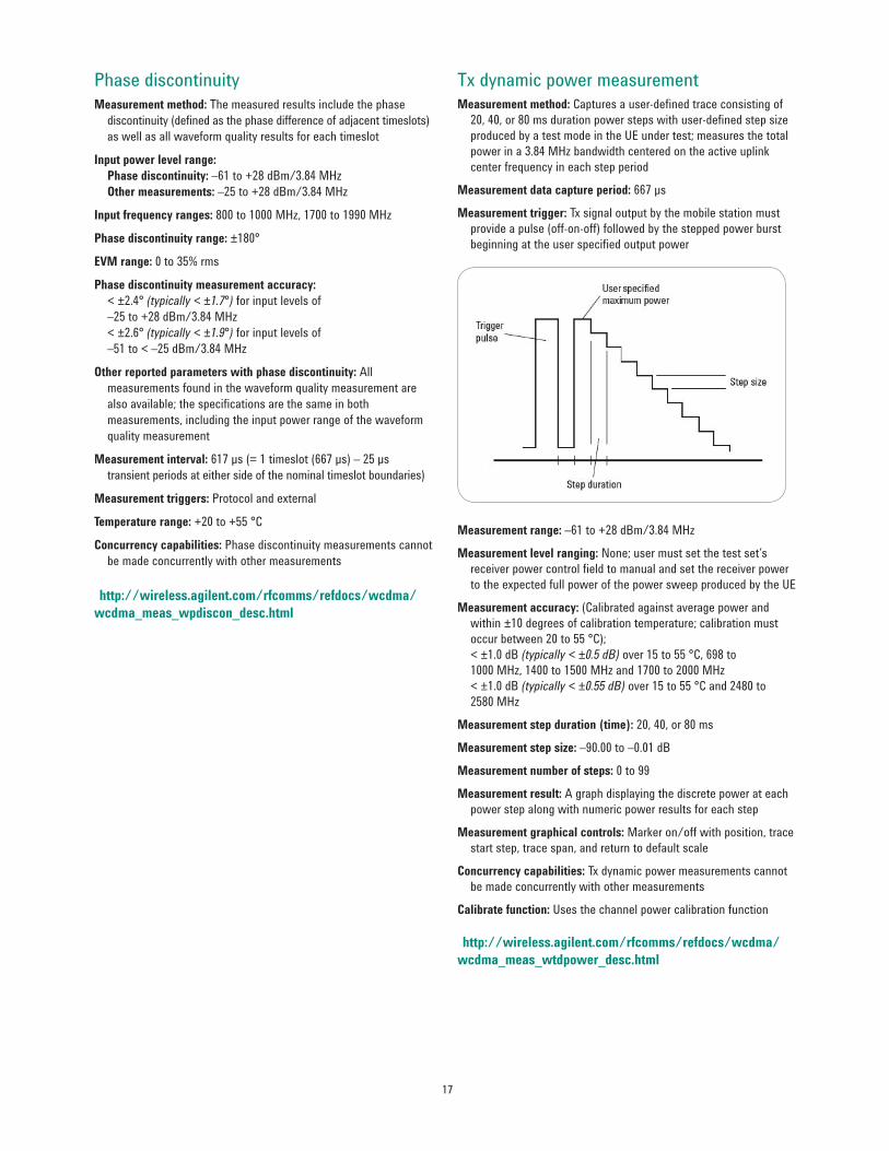
Tx dynamic power measurement Measurement method Captures a user-defined trace consisting of 20 40 or 80 ms duration power steps with user-defined step size produced by a test mode in the UE under test measures the total power in a 384 MHz bandwidth centered on the active uplink center frequency in each step period
Measurement data capture period 667micros
Measurement trigger Tx signal output by the mobile station must provide a pulse (off-on-off) followed by the stepped power burst beginning at the user specified output power
Measurement range ndash61 to +28 dBm384 MHz
Measurement level ranging None user must set the test setrsquos receiver power control field to manual and set the receiver power to the expected full power of the power sweep produced by the UE
Measurement accuracy (Calibrated against average power and within plusmn10 degrees of calibration temperature calibration must occur between 20 to 55 degC) lt plusmn10 dB (typically lt plusmn05 dB) over 15 to 55 degC 698 to 1000MHz1400to1500MHzand1700to2000MHz lt plusmn10 dB (typically lt plusmn055 dB) over 15 to 55 degC and 2480 to 2580 MHz
Measurement step duration (time) 20 40 or 80 ms
Measurement step size ndash9000 to ndash001 dB
Measurement number of steps 0 to 99
Measurement result A graph displaying the discrete power at each power step along with numeric power results for each step
Measurement graphical controls Marker onoff with position trace start step trace span and return to default scale
Concurrency capabilities Tx dynamic power measurements cannot be made concurrently with other measurements
Calibrate function Uses the channel power calibration function
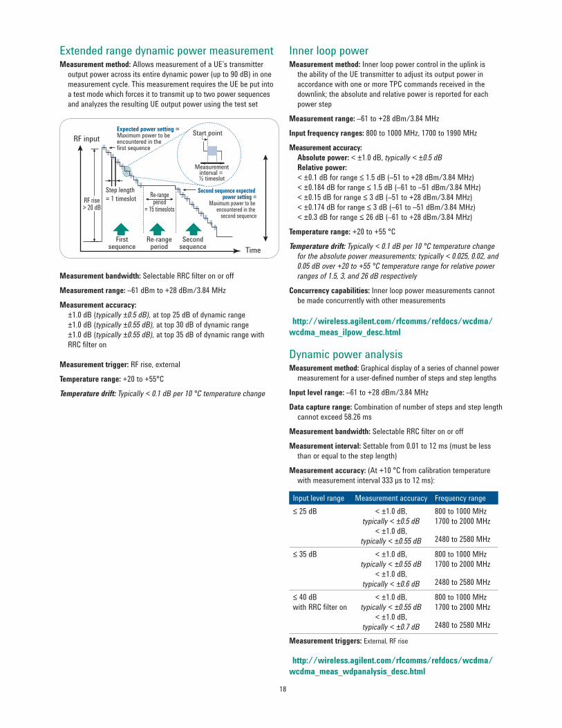
Extended range dynamic power measurement Measurement method Allows measurement of a UErsquos transmitter output power across its entire dynamic power (up to 90 dB) in one measurement cycle This measurement requires the UE be put into a test mode which forces it to transmit up to two power sequences and analyzes the resulting UE output power using the test set
RF inputExpected power setting =Maximum power to beencountered in the first sequence
Step length= 1 timeslot Re-range
period= 15 timeslots
Second sequence expected power setting =
Maximum power to be encountered in the
second sequence
Firstsequence
Secondsequence
Re-rangeperiod Time
Start point
Measurementinterval = frac12 timeslot
RF risegt 20 dB
Measurement bandwidth Selectable RRC filter on or off
Measurement range ndash61 dBm to +28 dBm384 MHz
Measurement accuracy plusmn10 dB (typically plusmn05 dB) at top 25 dB of dynamic range plusmn10 dB (typically plusmn055 dB) at top 30 dB of dynamic range plusmn10 dB (typically plusmn055 dB) at top 35 dB of dynamic range with RRC filter on
Measurement trigger RF rise external
Temperature range +20 to +55degC
Temperature drift Typically lt 01 dB per 10 degC temperature change
Inner loop power Measurement method Inner loop power control in the uplink is the ability of the UE transmitter to adjust its output power in accordance with one or more TPC commands received in the downlink the absolute and relative power is reported for each power step
Measurement range ndash61 to +28 dBm384 MHz
Input frequency ranges800to1000MHz1700to1990MHz
Measurement accuracy Absolute power lt plusmn10 dB typically lt plusmn05 dB Relative power lt plusmn01 dB for range le 15 dB (ndash51 to +28 dBm384 MHz) lt plusmn0184 dB for range le 15 dB (ndash61 to ndash51 dBm384 MHz) lt plusmn015 dB for range le 3 dB (ndash51 to +28 dBm384 MHz) ltplusmn0174dBforrangele 3 dB (ndash61 to ndash51 dBm384 MHz) lt plusmn03 dB for range le 26 dB (ndash61 to +28 dBm384 MHz)
Temperature range +20 to +55 degC
Temperature drift Typically lt 01 dB per 10 degC temperature change for the absolute power measurements typically lt 0025 002 and 005 dB over +20 to +55 degC temperature range for relative power ranges of 15 3 and 26 dB respectively
Concurrency capabilities Inner loop power measurements cannot be made concurrently with other measurements
Dynamic power analysis Measurement method Graphical display of a series of channel power measurement for a user-defined number of steps and step lengths
Input level range ndash61 to +28 dBm384 MHz
Data capture range Combination of number of steps and step length cannot exceed 5826 ms
Measurement bandwidth Selectable RRC filter on or off
Measurement interval Settable from 001 to 12 ms (must be less than or equal to the step length)
Measurement accuracy (At +10 degC from calibration temperature with measurement interval 333 micros to 12 ms)
Input level range Measurement accuracy Frequency rangele 25 dB lt plusmn10 dB
Rx measurements Loopback bit error ratio Measurement method Data loopback (mode 1 in 3GPP TS 34109)
BER measurement input level range ndash50 to +28 dBm384 MHz
Reported parameters Intermediate results Measured bit error ratio number of errors number of bits tested uplink missing blocks uplink CRC errors and loopback delay Final results Measured BER number of errors number of bits tested uplink missing blocks CRC errors and loopback delay
Concurrency capabilities BER measurements cannot be made concurrently with BLER phase discontinuity PRACH Tx onoff or inner loop power measurements or while speech is provided on the downlink loopback BER measurements can be made concurrently with all other measurements
Block error ratio Measurement method The UE is configured to loop back the data bits and the CRC bits from the downlink transport blocks into the uplink transport blocks on the DPCH a comparison is made in the test set by generating a CRC using the data bits received on the uplink and comparing the calculated CRC against the CRC received in the uplink transport block
BLER measurement input level range ndash50 to +28 dBm384 MHz
Reported parameters Measured BLER block error count number of blocks tested and uplink missing blocks
Concurrency capabilities BLER measurements cannot be made concurrently with loopback BER phase discontinuity PRACH Tx onoff or inner loop power measurements or while speech is provided on the downlink BLER measurements can be made concurrently with all other measurements
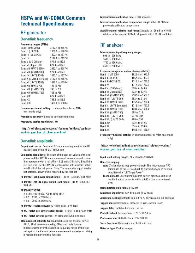
Downlink amplitude Output port control Control of RF source routing to either the RF INOUT port or the RF OUT ONLY port Composite signal level The sum of the user-set values of the cell power and the AWGN source measured in a root-raised cosine filter response with a roll off α = 022 and a 384 MHz BW if the cell power is ON the AWGN level must be set to within ndash20 dB to +10 dB of the cell power Note The composite signal level is not settable however it is reported by the test set
RF INOUT cell power output range ndash115 to ndash13 dBm384 MHz
RF INOUT AWGN signal output level range ndash115 to ndash20 dBm 384 MHz
RF OUT ONLY cell power output range ndash115 to ndash5 dBm384 MHz
RF OUT ONLY reverse power +24 dBm peak (250 mW peak)
Measurement calibrate function Calibrates the channel power ACLR SEM waveform quality OBW and code domain measurements over the specified frequency range of the test set against the thermal power measurement no external cabling is required to perform this function
Measurement calibration time lt 180 seconds
Measurement calibration temperature range Valid plusmn10 degC from previously calibrated temperature
AWGN channel relative level range Settable to ndash20 dB to +10 dB relative to the user-set CDMA cell power with 001 dB resolution
RF analyzer Measurement input frequency ranges 698 to 1000 MHz 1400 to 1500 MHz 1700to1990MHz 2480 to 2580 MHz
Frequency ranges for uplink channels (MHz) BandI(IMT-2000) 19224to19776BandII(USPCS) 18524to19076BandIII(DCSPCS) 17124to17826BandIV 17124to17526Band V (US Cellular) 8264 to 8466 BandVI(Japan800) 8324to8376BandVII(UMTS2600) 25024to25676Band VIII (UMTS 900) 8824 to 9126 BandIX(UMTS1700) 17524to17824BandX(UMTSExtended) 17124to17676BandXI(UMTS1500) 14304to14504BandXII(UMTS700) 698to716BandXIII(UMTS700) 777to787BandXIV(UMTS700) 788to798BandXIX 8324to8426BandXX 8344to8596BandXXI 14504to14604
FrequencyChannel setting By channel number or MHz (test mode only)
Receiver ranging Auto (Active closed loop power control) The test set uses TPC commands to the UE to adjust its transmit power as needed to achieve the ldquoUE Target Powerrdquo Manual mode User enters expected power provides calibrated results if actual power is within plusmn9 dB of the user-entered level
Demodulation chip rate 384 Mcps
Maximum input level +37dBmpeak(5Wpeak)
Amplitude scaling Settable from 01 to 20 dBdivision in 01 dB steps
Trigger source Immediate protocol RF rise external auto
Trigger delay Settable between plusmn50 ms
Peak threshold Settablefromndash120to+37dBm
Peak excursion Settable from 12 to 100 dB
Trace functions Clear write max hold min hold
Detector type Peak or sample
21
Tx measurements
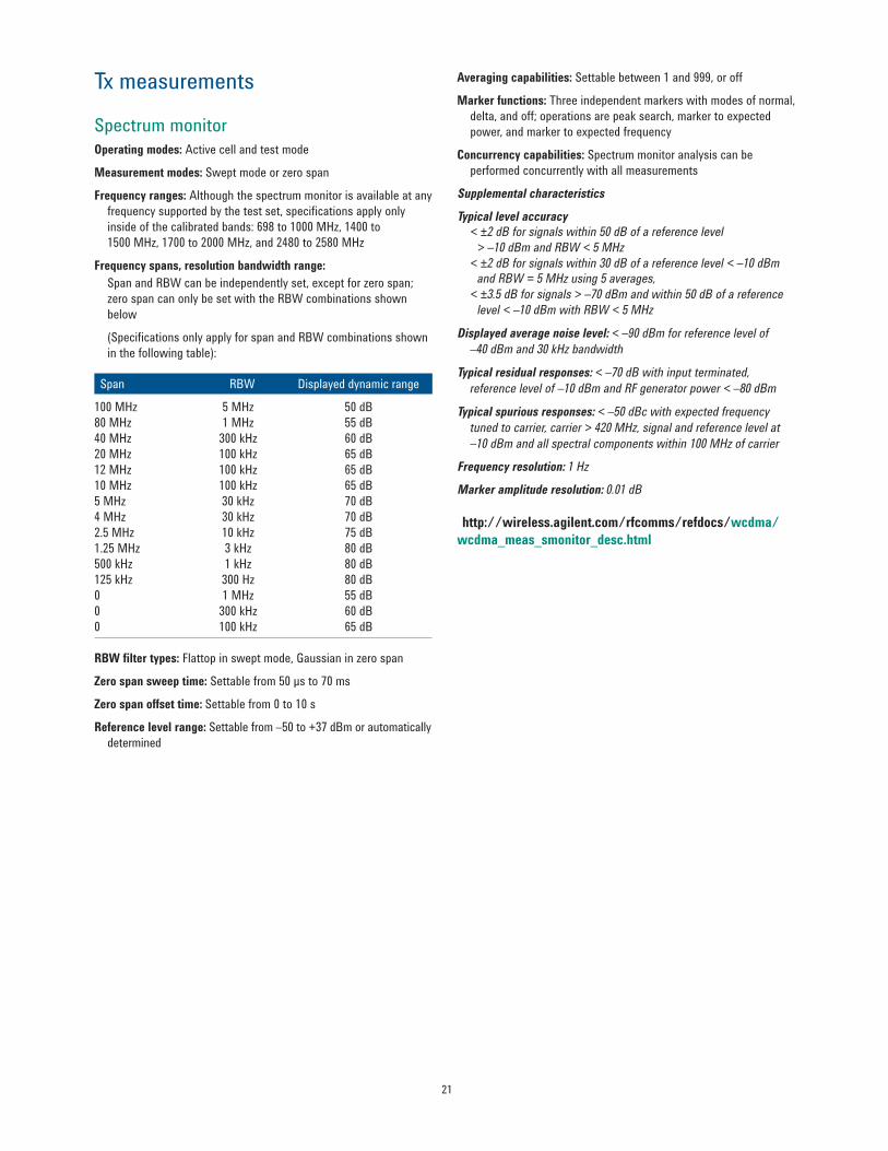
Spectrum monitor Operating modes Active cell and test mode
Measurement modes Swept mode or zero span
Frequency ranges Although the spectrum monitor is available at any frequency supported by the test set specifications apply only inside of the calibrated bands 698 to 1000 MHz 1400 to 1500MHz1700to2000MHzand2480to2580MHz
Frequency spans resolution bandwidth range Span and RBW can be independently set except for zero span zero span can only be set with the RBW combinations shown below
(Specifications only apply for span and RBW combinations shown in the following table)
RBW filter types Flattop in swept mode Gaussian in zero span
Zero span sweep time Settablefrom50microsto70ms
Zero span offset time Settable from 0 to 10 s
Reference level range Settablefromndash50to+37dBmorautomatically determined
Averaging capabilities Settable between 1 and 999 or off
Marker functions Three independent markers with modes of normal delta and off operations are peak search marker to expected power and marker to expected frequency
Concurrency capabilities Spectrum monitor analysis can be performed concurrently with all measurements
Supplemental characteristics
Typical level accuracy lt plusmn2 dB for signals within 50 dB of a reference level gt ndash10 dBm and RBW lt 5 MHz lt plusmn2 dB for signals within 30 dB of a reference level lt ndash10 dBm and RBW = 5 MHz using 5 averages lt plusmn35 dB for signals gt ndash70 dBm and within 50 dB of a reference level lt ndash10 dBm with RBW lt 5 MHz
Displayed average noise level lt ndash90 dBm for reference level of ndash40 dBm and 30 kHz bandwidth
Typical residual responses lt ndash70 dB with input terminated reference level of ndash10 dBm and RF generator power lt ndash80 dBm
Typical spurious responses lt ndash50 dBc with expected frequency tuned to carrier carrier gt 420 MHz signal and reference level at ndash10 dBm and all spectral components within 100 MHz of carrier
Audio analyzer expandor Settable as off or on with reference level setting of 10 mV to 10 V
Audio analyzer filters Settable choices of none C-message 50 Hz to 15 kHz band pass 300 Hz to 15 kHz band pass or 100 Hz band width tunable band pass tunable over 300 Hz to 15 kHz
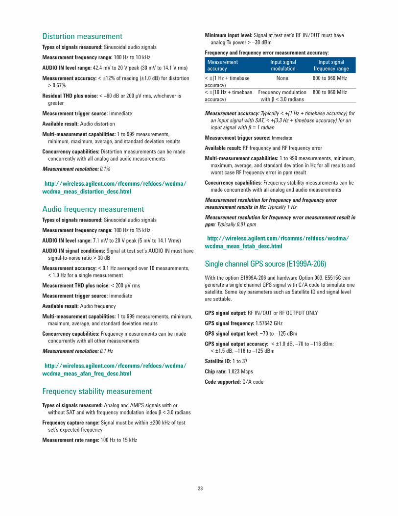
Frequency stability measurement Types of signals measured Analog and AMPS signals with or without SAT and with frequency modulation index β lt 30 radians
Frequency capture range Signal must be within plusmn200 kHz of test setrsquos expected frequency
Measurement rate range 100 Hz to 15 kHz
Minimum input level Signal at test setrsquos RF INOUT must have analog Tx power gt ndash30 dBm
Frequency and frequency error measurement accuracy Measurement accuracy
Input signalmodulation
Input signal frequency range
lt plusmn(1 Hz + timebase None 800 to 960 MHz accuracy) lt plusmn(10 Hz + timebase Frequency modulation 800 to 960 MHz accuracy) with β lt 30 radians
Measurement accuracy Typically lt +(1 Hz + timebase accuracy) for an input signal with SAT lt +(33 Hz + timebase accuracy) for an input signal with β = 1 radian
Measurement trigger source Immediate
Available result RF frequency and RF frequency error
Multi-measurement capabilities 1 to 999 measurements minimum maximum average and standard deviation in Hz for all results and worst case RF frequency error in ppm result
Concurrency capabilities Frequency stability measurements can be made concurrently with all analog and audio measurements
Measurement resolution for frequency and frequency error measurement results in Hz Typically 1 Hz
Measurement resolution for frequency error measurement result in ppm Typically 001 ppm
Single channel GPS source (E1999A-206) With the option E1999A-206 and hardware Option 003 E5515C can generate a single channel GPS signal with CA code to simulate one satellite Some key parameters such as Satellite ID and signal level are settable
GPS signal output RF INOUT or RF OUTPUT ONLY
GPS signal frequency 157542GHz
GPS signal output level minus70tondash125dBm
GPS signal output accuracy ltplusmn10dBndash70tondash116dBm lt plusmn15 dB ndash116 to ndash125 dBm
Satellite ID 1to37
Chip rate 1023 Mcps
Code supported CA code
24
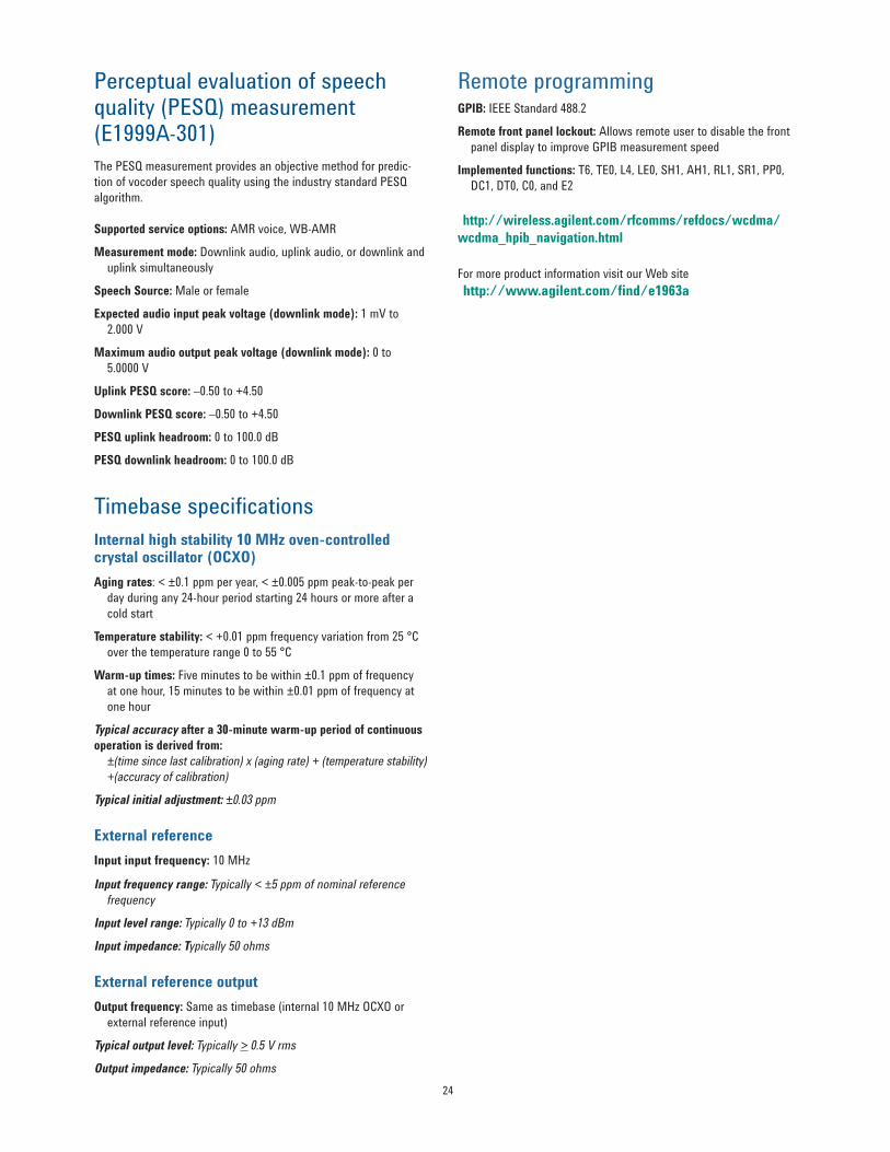
Perceptual evaluation of speech quality (PESQ) measurement (E1999A-301) The PESQ measurement provides an objective method for predic-tion of vocoder speech quality using the industry standard PESQ algorithm
Supported service options AMR voice WB-AMR
Measurement mode Downlink audio uplink audio or downlink and uplink simultaneously
Speech Source Male or female
Expected audio input peak voltage (downlink mode) 1 mV to 2000 V
Maximum audio output peak voltage (downlink mode) 0 to 50000 V
Uplink PESQ score ndash050 to +450
Downlink PESQ score ndash050 to +450
PESQ uplink headroom 0 to 1000 dB
PESQ downlink headroom 0 to 1000 dB
Timebase specifications Internal high stability 10 MHz oven-controlled crystal oscillator (OCXO) Aging rates lt plusmn01 ppm per year lt plusmn0005 ppm peak-to-peak per day during any 24-hour period starting 24 hours or more after a cold start
Temperature stability lt +001 ppm frequency variation from 25 degC over the temperature range 0 to 55 degC
Warm-up times Five minutes to be within plusmn01 ppm of frequency at one hour 15 minutes to be within plusmn001 ppm of frequency at one hour
Typical accuracy after a 30-minute warm-up period of continuous operation is derived from plusmn(time since last calibration) x (aging rate) + (temperature stability) +(accuracy of calibration)
Typical initial adjustment plusmn003 ppm
External referenceInput input frequency 10 MHz
Input frequency range Typically lt plusmn5 ppm of nominal reference frequency
For more product information visit our Web site (httpwwwagilentcomfinde1963a)
myAgilent
myAgilent
wwwagilentcomfindmyagilentA personalized view into the information most relevant to you
Three-Year Warranty
wwwagilentcomfindThreeYearWarrantyBeyond product specification changing the ownership experience Agilent is the only test and measurement company that offers three-year warranty on all instruments worldwide
Agilent Assurance Plans
wwwagilentcomfindAssurancePlansFive years of protection and no budgetary surprises to ensure your instruments are operating to specifications and you can continually rely on accurate measurements
wwwagilentcomquality
Agilent Electronic Measurement GroupDEKRA Certified ISO 90012008 Quality Management System
wwwagilentcomwwwagilentcomfindE1963A
For more information on Agilent Technologiesrsquo products applications or services please contact your local Agilent office The complete list is available atwwwagilentcomfindcontactus
cdma2000 is a US registered certification mark of the Telecommunications Industry Association
2
Key Capabilities bull CSvoicehandoversbetweenGSMandW-CDMAontwotestsetsbull Fast device calibration across level and frequency simultaneouslybull Test HSDPA MIMO devices (HS-DSCH categories 15-20) as defined in 3GPP TS 34121-1 bull Test devices that support downlink dual carrier and dual band dual carrier (HS-DSCH categories 20-24) bull TestHSPAdevices(HS-DSCHcategories1-1417-18andE-DCH categories1-7)asdefinedin3GPPTS34121-1bull SwitchbetweenHSPAsub-testconditionswhileonanactive connection bull TestallUMTStechnologieswithoneconnectionmaintained throughout bull TestallfrequencybandsIthroughXIVXIXXXandXXIbull FMandGPSreceivercalibrationinoneboxbull TestvocoderspeechqualityusingtheindustrystandardPESQ algorithm
Tx measurements W-CDMA HSDPA HSUPA Thermal power Yes Yes Yes Channel power Yes Yes Yes Adjacent channel leakage ratio Yes Yes Yes Waveform quality Yes Yes Yes Spectrum emission mask Yes Yes Yes Phase discontinuity Yes Yes Yes Inner loop power Yes Occupied bandwidth Yes Yes Yes Code domain power Yes Yes Yes IQ constellation Yes Yes Yes Tx onoff power Yes Yes Yes Frequency stability Yes Yes Yes Dynamic power analysis Yes Yes Yes Tx dynamic power Yes Spectrum monitor Yes Yes Yes Rx measurements W-CDMA HSDPA HSUPA Loopback BER Yes NA NA BLER on DPCH (W-CDMA) Yes NA NA HBLER on HS-DPCCH (HSDPA) NA Yes NA
3
3GPP TS 34121 Adherence 3GPP TS 34121-1
Test description E1963A52 Maximum output power Yes 52A Maximum output power with HS-DPCCH
(Release 5 only)Yes5
52AA Maximum output power with HS-DPCCH(Release 6 and later)
Yes5
52B Maximum output power with HS-DPCCH and E-DCH
Yes5
52C UE relative code domain power accuracy Yes5
52D UE relative code domain power accuracy forHS-DPCCH and E-DCH
Yes5
52E UE relative code domain power accuracyfor HS-DPCCH and E-DCH with 16QAM
Yes5
53 Frequency error Yes 541 Open-loop power control Yes 542 Inner-loop power control Yes 543 Minimum output power Yes 544 Out-of-sync handling of output power E6703X2
551 Transmit off power Yes552 Transmit onoff time mask Yes 56 Change of TFC E6703X57 Power setting in UL compressed mode57A HS-DPCCH Yes5 58 Occupied bandwidth (OBW) Yes59 Spectrum emission mask (SEM) Yes 59A Spectrum emission mask with HS-DPCCH Yes5 59B Spectrum emission mask with E-DCH Yes5
64B Adjacent channel selectivity (ACS) for DC-HSDPA Yes1
64C Adjacent channel selectivity (ACS) for DB-DC-HSDPA Yes1
65 Blocking characteristics Yes1
65A Blocking characteristics for DC-HSDPA Yes1
65B Blocking characteristics for DB-DC-HSDPA Yes1
66 Spurious response Yes1
66A Spurious response for DC-HSDPA Yes1
66B Spurious response for DB-DC-HSDPA Yes1
67 Intermodulation characteristics Yes1
67A Intermodulation characteristics for DC-HSDPA Yes1
67B Intermodulation characteristics for DB-DC-HSDPA Yes1
68 Spurious emissions Yes1
72 Demod in static propagation Yes73 Demod in multi-path E6703X4
74 Demod in moving channel E6703X4
75 Demod in birth-death E6703X4
1 Requires use of external source 2 Requires use of external spectrum analyzer 3 Requires use of external spectrum analyzer and source 4 Internal fading is possible using the N5106A PXB baseband generator and channel emulator Most of these tests require external instrumentation such as faders Consult TS 34121-1 for details5 Requires feature option license
4
Related Literature Technical Specifications The Most Complete Test Functionality for HSPAW-CDMA Wireless Devices photocard(5989-3414EN)Agilent 8960 Wireless Communications Test Set HSPA Applications photocard 5989-7515EN 8960 Series 10 Wireless Communications Test Set configuration guide 5968-7873E
For More Information Learn more about the E1963A test application and HSPA options at wwwagilentcomfindE1963A
Technical Specifications These specifications apply to an E5515CE mainframe with Option 003 when used with the latest E1963A test application ortheE1987Atestapplication
Specifications describe the test setrsquos warranted performance and are valid for the unitrsquos operation within the stated environmental ranges unless otherwise noted All specifications are valid after a 30-minute warm-up period of continuous operation
Supplemental characteristics are intended to provide typical but non-warranted performance parameters that may be useful in apply-ing the instrument These characteristics are shown in italics and labeled as ldquotypicalrdquo All units shipped from the factory meet these typical numbers at +25 degC ambient temperature without including measurement uncertainty
What is Included in This Technical Overview This data sheet is organized in four sections bull HSPAspecificationsbull W-CDMAspecificationsbull HSPAandW-CDMAcommontechnicalspecificationsbull Generalspecifications
Call connection types HSPA FDD test mode HSPA FDD test modes are supported by the E1963A FDD test mode provides Layer 1 functionality only No higher-level signaling is provided or accepted No higher-level call processing operations are performed The test set assumes that you have appropriately configured the UE
FDD test mode allows you to test the parametric performance of your UErsquos transmitter and receiver without call processing In FDD test mode the test set does not send any signaling information on the downlink Rather it continuously generates a downlink signal and searches for a corresponding uplink signal The UE must synchronize to the downlink signal and send an appropriate uplink signal which the test set uses to measure the UErsquos transmitter and receiver perfor-mance Any changes to the UE configuration must be accomplished by directly sending commands to the UE from a system controller through a proprietary digital interface
FRC H-set support H-Set Modulation Nominal avg inf bit rate (Mbps)
1 QPSK 16QAM 053407772 QPSK 16QAM 0801 1166
33A QPSK 16QAM 1601 2332 4 QPSK 0534 5 QPSK 0801
66A QPSK 16QAM 3219 4689 88A 64QAM 13252
9 16QAM QPSK 878448681010A QPSK 16QAM 4868774
11 64QAM 16QAM 13300877412 QPSK 006
Note For DC-HSDPA H-Sets 3A 6A 8A 10A and 12 the nominal avg inf bit rateis for each of the serving cells For HSDPA MIMO H-Sets 9 and 11 the nominalavginf bit rate is for each of the transport blocks
HSPA RB test mode RB test mode uses signaling to establish a test control connection between the test set and UE allowing you to test the parametric performance of your UErsquos transmitter and receiver In RB test mode the test set provides signaling to establish a connection between the UE and the test set The test set can also signal the UE to change its configuration and alter the uplink signal The test set measures the uplink signal to determine the UErsquos transmitter and receiver perfor-mance RB test mode is operated on the downlink simultaneously supporting a symmetrical RMC (reference measurement channel) of 122 kbps This symmetrical RMC is typically used for transmitter testing and receiver testing using BER
HSPA handovers To support the HSPA tests and sub-test conditions specified in the 3GPP standards the transport channel reconfiguration procedure allows you to change HSPA parameters while on a live connection βc βd ∆ACK ∆NACK ∆CQI CQI feedback cycle (k) CQI repetition factor Ack-Nack repetition factor and default DPCH offset (DOFF) parameters can all be modified without dropping the HSPA connection In addition when using the user-defined DL configuration for HSDPA in RB test mode the number of HARQ processes and UE IR buffer size can be changed on a live HSDPA connection to provide flexibility in testing multiple configurations
The radio bearer reconfiguration allows handover from a CS domain or CSPS domain HSDPA RB test mode connection or HSPA RB test mode connection to a (non-HSDPAnon-HSPA) symmetrical RMC The radio bearer reconfiguration also allows you to change many other network parameters as part of the reconfiguration
You can also handover between channels within a band and between bands using the physical channel reconfiguration procedure This allows you to test channels in the low middle and high frequency portions of each UE-supported band without dropping the HSPA connection
Inter-system handovers Almost all UE supports multiple formats today To speed the process of testing multiple formats with call processing you can perform handovers from HSPA to GSM and from HSPA to W-CDMA If your test plan requires testing HSPA followed by GSM GPRS andor EGPRS you can hand over from an HSPA FRC to GSM test mode using the system handover If your test plan requires testing W-CDMA as well you can hand over from an HSPA FRC to a W-CDMA RMC then use the existing W-CDMA RMC to GSM test mode system handover to test GSM GPRS andor EGPRS
HSDPA user-defined downlink Verify your devicersquos HSDPA throughput at the MAC-hs or MAC-ehs level with the user-defined downlink (DL) in E1963A Option 403 405 423 433 and 435 Verify HS-DSCH category 15-20 HSDPA MIMO devices through to providing up to a 28 Mbps or 42 Mbps radio bearer (RB) test mode signal Set the configurationrsquos flexibly of HSDPA MIMO state each antenna channel configuration the number of transport blocks and active HS-PDSCHs each transport block size index modulation type of each transport block inter-TTI number of HARQ processes and UE incremental redundancy (IR) buffer size Configure the E5515CE to provide up to a 42 Mbps RB test mode signal for testing HS-DSCH category 24 dual carrier or dual band dual carrier devices
Common pilot channel relative level ndash20 to 0 dB
Primary CCPCH relative level ndash20 to 0 dB
PICH relative level ndash20 to 0 dB
DPCH relative level Settable from ndash30 to 0 dB with 001 dB resolution
HS-SCCH relative level of individual code channels HS-SCCH channel can be off but at least one channel is in pres-ence For 64QAM downlink at least two channels are in presence The channel level is settable from ndash20 to 0 dB
HS-PDSCH relative level of all active code channels Settable from ndash20 to 0 dB
Primary sync channel relative level Always the same as P-CCPCH
For DC-HSDPA the channel default assignment code choices and relative levels are the same for each of the serving cells except that DPCH is only for the primary serving cell and the maximum number of HS-SCCHs across both serving cells is 6
For HSDPA MIMO the pilot channel for each antenna can be config-ured P-CPICH is configured on antenna 1 and P-CPICH or S-CPICH can be configured on antenna 2 and the relative level (power offsets from the cell power of the channels transmitted on antenna 1 or 2) is ndash20 to 0 dB
When HSDPA MIMO is active the same number of HS-PDSCHs is transmitted on both antennas with the same channelization codes The existing power levels of HS-PDSCHs specified in the power offset parameters are the power offsets of all HS-PDSCHs transmit-ted on both antennas relative to the cell power The power of each HS-PDSCH is split equally on both antennas
RF INOUT composite signal absolute output level accuracy (DC-HSDPA) AWGN off lt plusmn12 dB (typically lt plusmn075 dB) at ndash109 to ndash15 dBm
384 MHz and lt 2300 MHz lt plusmn16 dB (typically lt plusmn11 dB) at ndash109 to ndash15 dBm 384 MHz and ge 2300 MHz
Downlink CDMA modulation Modulation type QPSK 16QAM and 64QAM per 3GPP standard QPSK residual EVM 10 typically lt 3 QPSK carrier feed through lt ndash25 dBc typically lt ndash35 dBc nominal ambient performance lt ndash45 dBc 16QAM residual EVM Typically lt 3 16QAM carrier feed through Typically lt ndash35 dBc nominal ambient performance lt ndash45 dBc 64QAM residual EVM Typically lt 6 64QAM carrier feedthrough Typically lt ndash35 dBc nominal ambient performance lt ndash45 dBc
RF OUT ONLY composite signal absolute output level accuracy (DC-HSDPA) AWGN off lt plusmn12 dB (typically lt plusmn075 dB) at ndash109 to ndash15 dBm 384 MHz and lt 2300 MHz lt plusmn16 dB (typically lt plusmn11 dB) at ndash109 to ndash15 dBm 384 MHz and ge 2300 MHz OCNS ndash orthogonal channel noise source Composed of 6 channels per Table E55 in Annex E of 3GPP 34121 OCNS channel can be off but at least 1 OCNS channel is in presence
OCNS channel relative level range Automatically calculated from other code channel relative levels to provide the composite W-CDMA cell power but user-allocated channel level available (httpwirelessagilentcomrfcommsrefdocswcdmawcdma_gen_bse_gen_infohtmlBCGCBAHE)
Tx measurements Channel power measurementInput signal modulation QPSK and 16QAM
Measurement bandwidth RRC filter off Measured with a bandwidth greater than (1 + α) x chip rate where α = 022 and chip rate = 384 Mcps RRC filter on Measured with a filter that has a root-raised cosine (RRC) filter response with roll-off α = 022 and a bandwidth equal to the chip rate 384 MHz centered on the active uplink channel)
Measurement range ndash61 to +28 dBm384 MHz
Measurement interval Settable from 001 to 12 ms
Measurement accuracy (at plusmn10 degC from the calibration temperature) lt plusmn10 dB (typically lt plusmn05 dB) for measurement intervals of 333 micros to 12 ms over 698 to 1024 MHz 1400 to 1500 MHz and 1700to2000MHz lt plusmn10 dB (typically lt plusmn055 dB) for measurement intervals of 333 micros to 12 ms over 2480 to 2580 MHz lt plusmn10 dB (typically lt plusmn06 dB) for measurement intervals of 67tolt333microsover698to1024MHz1400to1500MHzand 1700to2000MHz
Measurement triggers Auto immediate protocol RF rise external and HS-DPCCH
Phase discontinuity Measurement method The measured results include the phase discontinuity (defined as the phase difference of adjacent timeslots) as well as all waveform quality results for each timeslot
Input power level range Phase discontinuity ndash61 to +28 dBm384 MHz Other measurements ndash25 to +28 dBm384 MHz
Input frequency ranges800to1000MHz1700to1990MHz
Phase discontinuity range plusmn180deg
EVM range 0 to 35 rms
Phase discontinuity measurement accuracy lt plusmn24deg (typically lt plusmn17deg) for input levels of ndash25 to +28 dBm384 MHz lt plusmn26deg (typically lt plusmn19deg) for input levels of ndash51 to lt ndash25 dBm384 MHz
Other reported parameters with phase discontinuity All measurements found in the waveform quality measurement are also available the specifications are the same in both measurements including the input power range of the waveform quality measurement
Measurement interval 617micros(=1timeslot(667micros)ndash25micros transient periods at either side of the nominal timeslot boundaries) or 283 micros (05 timeslot (333 micros) ndash 25 micros transient periods at either side of the nominal timeslot boundaries)
Measurement triggers Protocol external and HS-DPCCH
Temperature range +20 to +55 degC
Concurrency capabilities Phase discontinuity measurements cannot be made concurrently with other measurements
Measurement interval 05 to 10 timeslot with choice to include or exclude 25 micros transient periods
EVM measurement accuracy (including the effects of residual EVM)
EVM measurement accuracy lt 28 rms (typically lt 24 rms) for UE EVM ge 1 rms le 2200 MHz lt 32 rms (typically lt 28 rms) for UE EVM ge 1 rms 2300 to 2580 MHz
Measurement triggers Auto protocol immediate external and HS-DPCCH
HS-DPCCH trigger alignment Adjustable over Subframes 0 to 5 Timeslots Ack Nack or CQI Subslots 0 to 05 timeslots
Other reported parameters with EVM bullFrequencyerrorbullMagnitudeerrorbullPhaseerrorbullOriginoffsetbullTimingerrorbullPeakcodedomainerror
Frequency error measurement range plusmn1 kHz
Residual frequency error lt plusmn(5 Hz + timebase accuracy) for a measurement interval of 1 timeslot ltplusmn(7Hz+timebaseaccuracy)forameasurementintervalof 05 timeslot
Frequency error measurement accuracy
Peak code domain error accuracy lt plusmn04 dB for code power levels gt ndash25 dB
IQ tuning All measurements found in the waveform quality measurement are also available in the IQ tuning measurement the specifications are the same in both measurements
Dynamic power analysis Measurement method Graphical display of the uplink power waveform including HS-DPCCH DPCH versus time by using the HS-DPCCH trigger source results will be aligned to the HS-DPCCH
Input power level range ndash61 to +28 dBm384 MHz
Measurement level ranging Auto
Data capture range Combination of number of steps and step length cannot exceed 5826 ms
Measurement bandwidth Selectable RRC filter on or off
Measurement interval Settable from 001 to 12 ms (must be less than or equal to the step length)
Measurement accuracy (At plusmn10 degC from calibration temperature with measurement interval 333 micros to 12 ms)
Input level range Measurement accuracy Frequency rangele 25 dB lt plusmn10 dB
typically lt plusmn05 dB lt plusmn10 dB
typically lt plusmn055 dB
800 to 1000 MHz 1700to2000MHz
2480 to 2580 MHz
le 35 dB lt plusmn10 dB typically lt plusmn055 dB
lt plusmn10 dB typically lt plusmn06 dB
800 to 1000 MHz1700to2000MHz 2480 to 2580 MHz
le 40 dB with RRC filter on
lt plusmn10 dB typically lt plusmn055 dB
lt plusmn10 dB typically lt plusmn07 dB
800 to 1000 MHz 1700to2000MHz 2480 to 2580 MHz
Measurement triggers RF rise external and HS-DPCCH
HS-DPCCH trigger alignment Adjustable over subframes 0 to 5 (httpwirelessagilentcomrfcommsrefdocswcdmawcdma_meas_wdpanalysis_deschtml)
HSPA code domain power Code domain power accuracy lt plusmn04 dB for code power level gt ndash25 dB
Relative code domain error (RCDE) accuracy le plusmn05 dB for RCDE level gt ndash20 dB
Relative code domain power accuracy (RCDPA) le plusmn02 dB for code power level from ge ndash10 to 0 dB le plusmn03 dB for code power level from ge ndash15 ndash10 dB le plusmn04 dB for code power level from ge ndash20 ndash15 dB
All measurements found in the waveform quality measurement are also available in the code domain measurement the specifications are the same in both measurements
Measurement triggers Immediate protocol external auto HS-DPCCH and even frame
Adjacent channel leakage ratio (ACLR) Measurement method Ratio of the filtered mean transmitted power to the filtered mean power in an adjacent channel both the transmitted and the adjacent channel powers are measured with a filter that has a RRC response with roll-off α = 022 and a band width equal to the chip rate
Input power level range +5 to +28 dBm384 MHz
Input frequency ranges 698 to 1000 MHz 1400 to 1500 MHz 1700to2000MHzand2480to2580MHz
Measurement level ranging Auto
Measurement accuracy lt plusmn08 dB (typically lt plusmn05 dB) including the effects of the residual floor for measurements at ndash33 dBc at plusmn5 MHz offsets and ndash43 dBc at plusmn10 MHz offsets and plusmn10 degC from the calibration temperature
Residual ACLR floor lt ndash48 dBc for plusmn5 MHz offsets lt ndash58 dBc for plusmn10 MHz offsets
Measurement triggers Auto protocol immediate external HS-DPCCH
Trigger alignment Adjustable over subframes 0 to 5
Measurement interval 1 timeslot
Measurement result dBc relative to in-channel transmitted power
Rx measurements HSDPAHSPA+ block error ratio Measurement method TestsetcountstheACKNACKstatDTXon UE HS-DPCCH and uses the results to calculate BLER BLER measurement input level range ndash50 to +28 dBm384 MHz
Reported parameters Measured BLER number of blocks tested throughput number of ACKs number of NACKs number of stat DTXsandmedianCQIWhenDC-HSDPAisconfiguredthreesets of these results are available serving cell secondary serving cell and the combined cells
Concurrency capability HSDPA BLER measurements cannot be made concurrently with phase discontinuity PRACH Tx onoff or inner loop power measurements or while speech is provided on the downlink HSDPA BLER measurements can be made concurrently with all other measurements including W-CDMA loopback BER and BLER
HSDPA bit error ratio Measurement method The 8960 can be configured so that BER can be measured externally using the 8960 downlink and external UE monitoring software
Spectrum emission mask (SEM) Measurement method Ratio of the transmitted power (384 MHz bandwidth RRC) to offset frequencies which are between 25 and 125 MHz away from the UE center carrier frequency the offset frequencies are measured in 30 kHz or 1 MHz bandwidths depending on the offset
Input power level range +5 to +28 dBm384 MHz
Input frequency ranges 698 to 1000 MHz 1400 to 1500 MHz 1700to2000MHzand2480to2580MHz
Measurement accuracy le plusmn15 dB (typically lt plusmn08 dB) for the following offsets (plusmn10 degC from the calibration temperature) Frequency offset Levels (dBm) Meas BW
Measurement accuracy for additional spectrum emission limits for bands II IV V X XII XIII and XIV Typically lt plusmn11 dB for the following offsets (plusmn10 degC from the calibration temperature)
Frequency offset Levels (dBm) Meas BW 25 to 35 MHz ndash15 dBm 30 kHz 35 to 125 MHz ndash13 or ndash15 dBm 1 MHz or 100 kHz Measurement triggers Auto protocol immediate external and
HS-DPCCH
HS-DPCCH trigger alignment Adjustable over subframes 0 to 5
W-CDMA Specifications Call connection types End-to-end video conferencing (Option 401) Loop back video conferencing (Option 402) The E1963A when configured as a two-instrument system provides true H324 call setup with live video and audio from both mobile devices With only one E5515C loop back video call can be setup with Option 402
Validate compatibility by testing interoperability between your mobile and the competitor models offered for the same network
bull Complete call setup mobile origination and mobile release bull 64 k circuit-switched UDI channel bull H324 call setup
AMR voice Standard voice call with audio loopback for a quick check of voice functionalityfor122kratealsomanymoreAMRratessuchas475515596774795102and122k
bull UE and BS origination 122 k bull UE and BS release
FDD test mode FDD test mode allows you to test the parametric performance of your UErsquos transmitter and receiver without call processing In FDD test mode the test set does not send signaling information on the downlink Rather it continuously generates a downlink signal and searches for a corresponding uplink signal The UE must synchronize to the downlink signal and send and appropriate uplink signal which the test set uses to measure the UErsquos transmitter and receiver performance Any changes to the UE configuration must be accom-plished by directly sending commands to the UE from a system controller through a proprietary digital interface
RB test mode Fast conformance test calls with significant configuration control and testing capabilities
BS origination and release Symmetrical configuration W-CDMA modes support symmetrical RMCs at 122 64 144 and 384 k rates These symmetrical RMCs are typically used for transmitter testing and receiver testing user BER (via loopback type 1) or BLER (via loopback type 2) Asymmetric configuration The asymmetrical RMCs use either a 122 or a 64 k channel on the uplink The primary purpose of the symmetrical RMCs is to provide a way to make a BLER measurement by counting retransmission requests that the UE sends There is no need for data loopback in this mode
Inter-system handover Dual-mode functionality is required for most W-CDMA phones as GSM is an integral part in the majority of devices shipping today Inter-system handovers provide a means to validate dual-mode performance at your desk instead of roaming on a real network When operated in conjunction with compressed mode this feature can very closely emulate the basics of a real handover as made on the network
bull Blind handovers from W-CDMA to GSM bull Configurable landing GSM cell bull Test control to GSM voice bull W-CDMA AMR voice to GSM voice
Spreading factor of 128 at the fixed OVSF codes of 2 1117233138475562697885 94 113 119
125
Channel code is settable within
available code range
RF generator level accuracy is derived from the 99th percentile observations with 95 confidence (corresponds to an expanded uncertainty with a 95 confidence (k=2)) at ambient conditions then qualified to include the environmental effects of temperature and humidity
RF INOUT cell power absolute output level accuracy AWGN off lt plusmn11 dB (typically lt plusmn065 dB) at ndash109 to ndash15 dBm384 MHz and lt 2300 MHz lt plusmn15 dB (typically lt plusmn10 dB) at ndash109 to ndash15 dBm384 MHz and ge 2300 MHz
RF INOUT composite signal absolute output level accuracy AWGN on lt plusmn12 dB at ndash80 to ndash20 dBm384 MHz and lt 2300 MHz typically lt plusmn075 dB over ndash109 to ndash20 dBm384 MHz and lt 2300 MHz lt plusmn16 dB at ndash80 to ndash20 dBm384 MHz and ge 2300 MHz typically lt plusmn11 dB at ndash109 to ndash20 dBm384 MHz and ge 2300 MHz
RF OUT ONLY cell power absolute output level accuracyAWGN off lt plusmn11 dB at ndash109 to ndash7 dBm384 MHz and lt 2300 MHz typically lt plusmn065 dB ndash109 to ndash15 dBm384 MHz lt plusmn15 dB typically lt plusmn10 dB at ndash109 to ndash15 dBm384 MHz and ge 2300 MHz
RF OUT ONLY composite signal absolute output level accuracy AWGN on lt plusmn12 dB at ndash80 to ndash12 dBm384 MHz and lt 2300 MHz typically lt plusmn075 dB at ndash109 to ndash20 dBm384 MHz and lt 2300 MHz lt plusmn16 dB at ndash80 to ndash20 dBm384 MHz and ge 2300 MHz typically lt plusmn11 dB at ndash109 to ndash20 dBm384 MHz and ge 2300 MHz
Common pilot channel relative level ndash20 to 0 dB
Primary sync channel relative level Always the same as P-CCPCH
Secondary sync channel relative level Always the same as P-CCPCH
Primary CCPCH relative level ndash20 to 0 dB
DPCH relative level Settable from ndash30 to 0 dB with 001 dB resolution
PICH relative level ndash20 to 0 dB
Downlink CDMA modulation Modulation type QPSK per 3GPP standard Residual EVM lt 10 typically lt 3 Carrier feed through lt ndash25 dBc typically lt ndash35 dBc nominal ambient performance lt ndash45 dBc
OCNS ndash orthogonal channel noise source Composed of 16 channels per Table E36 in Annex E of 3GPP 34121
OCNS channel relative level range Automatically calculated from other code channel relative levels to provide the set CDMA cell power
Relative CDMA channel level accuracy lt plusmn02 dB (httpwirelessagilentcomrfcommsrefdocswcdmawcdma_gen_bse_gen_infohtmlBCGCBAHE)
13
W-CDMA RF analyzer (measurements only)
Real-time demodulation of Uplink DPCH
W-CDMA Tx measurements Thermal power measurement Measurement bandwidth gt 5 MHz if other signals are present outside of this frequency range reduced measurement accuracy will result
Measurement data capture period 10 ms
Measurement range ndash10 to +28 dBm usable to ndash20 dBm with degraded accuracy
Measurement level ranging Auto
Auto zero function Measurement automatically zeros the thermal power meter (no user control)
Channel power measurement Measurement bandwidth RRC filter off Measured with a bandwidth greater than (1 + α) x chip rate where α = 022 and chip rate = 384 Mcps RRC filter on Measured with a filter that has a root-raised cosine (RRC) filter response with roll-off α = 022 and a bandwidth equal to the chip rate (384 MHz bandwidth centered on the active uplink channel) Measurement range ndash61 to +28 dBm384 MHz
Measurement interval Settable from 001 to 12 ms
Measurement triggers Auto immediate protocol external and RF rise
Measurement accuracy (at +10 degC from the calibration temperature)
lt plusmn10 dB (typically lt plusmn05 dB) for measurement intervals of 333 micros to 12 ms over 698 to 1024 MHz 1400 to 1500 MHz and 1700to2000MHz lt plusmn10 dB (typically lt plusmn055 dB) for measurement intervals of 333 micros to 12 ms over 2480 to 2580 MHz lt plusmn10 dB (typically lt plusmn055 dB) for measurement intervals of 67tolt333microsover698to1024MHz1400to1500MHzand1700to2000MHz
Temperature range +20 to +55 degC
Temperature drift Typically 01 dB per 10 degC temperature change (httpwirelessagilentcomrfcommsrefdocswcdmawcdma_meas_chanpow_deschtml)
14
Fast device tune measurement Description Allows simultaneous calibration of a devicersquos Tx
output power and Rx input level across level and frequency in a single sweep (per frequency band) The device must operate in a test mode which forces it to transmit a predefined series of power steps at various uplink frequencies and also forces it to simultaneously tune its receiver to perform measurements (such as RSSI) of the test setrsquos signal at various downlink frequencies and power levels
Input frequency ranges 698 to 1000 MHz 1400 to 1500 MHz 1700to1990MHzand2480to2580MHz
Tx power measurement input level range ndash61 to +28 dBm384 MHz
Tx power measurement level change between adjacent steps lt 20 dB for 20 ms step size lt 10 dB for 10 ms step size
Tx power measurement accuracy (at +10 degrees from calibration temperature) lt plusmn10 dB
Rx level output range at RF INOUT port ndash109 to ndash15 dBm384 MHz
Rx level output range at RF OUT ONLY port ndash109tondash7dBm384MHz
Rx level change between adjacent steps lt 20 dB
Rx level accuracy with W-CDMA modulation lt plusmn11 dB
Rx level setting lt 51 ms to be within 01 dB
Concurrency capabilities Fast device tune measurements cannot be made concurrently with other measurements
IQ tuning All measurements found in the waveform quality measurement are also available in the IQ tuning measurement the specifications are the same in both measurements
Measurement accuracy (including the effects of residual EVM)
EVM measurement accuracy lt 28 rms (typically lt 24 rms) for UE EVM ge 1 rms le 2200 MHz lt 32 rms (typically lt 28 rms) for UE EVM ge 1 rms 2300 to 2580 MHz
Other reported parameters with EVM bull Frequency error bull Magnitude error bull Phase error bullOriginoffsetbull Timing error bull Peak code domain error
Frequency error measurement range plusmn1 kHz
16
Occupied bandwidth (OBW) Measurement method Bandwidth containing 99 of the total integrated power of the transmitted signal centered on the channel frequency
Input power level range +5 to +28 dBm
Input frequency ranges800to1000MHz1700to1990MHz
Measurement accuracy lt plusmn60 kHz
Measurement triggers Auto protocol immediate and external
Code domain power Code domain power accuracy le plusmn03 dB for code power level gt ndash25 dB
All measurements found in the waveform quality measurement are also available in the code domain measurement the specifications are the same in both measurements
PRACH transmit onoff power Measurement method The measure of the ON power of the PRACH preamble burst along with the OFF power preceding the burst and the OFF power following the burst
Input power level range
ON power ndash40 to +28 dBm384 MHz
OFF power ndash61 to ndash55 dBm384 MHz
Input frequency ranges800to1000MHz1700to1990MHz
Measurement accuracy lt plusmn10 dB (typically lt plusmn05 dB) within plusmn10 degC from the calibration temperature
Nominal trigger range Expected power plusmn9 dB
Temperature range +20 to +55 degC
Concurrency capabilities PRACH Tx onoff measurements cannot be made concurrently with other measurements
1 Refer to HSPA SEM specification on page 9 for additional requirements
Adjacent channel leakage ratio (ACLR) Measurement method Ratio of the filtered mean transmitted power to the filtered mean power in an adjacent channel both the transmitted and the adjacent channel powers are measured with a filter that has a RRC response with roll-off α = 022 and a band width equal to the chip rate
Input power level range +5 to +28 dBm384 MHz Input frequency ranges 698 to 1000 MHz 1400 to 1500 MHz 1700to 2000 MHz and 2480 to 2580 MHz Measurement level ranging Auto Measurement triggers Auto protocol immediate and external Measurement interval 1 timeslot Measurement result dBc relative to in-channel transmitted power
Measurement accuracy lt plusmn08 dB (typically lt plusmn05 dB) including the effects of the residual floor for measurements at ndash33 dBc at plusmn5 MHz offsets and ndash43 dBc at plusmn10 MHz offsets and plusmn10 degC from the calibration temperature
Residual ACLR floor lt ndash53 dBc for plusmn5 MHz offsets lt ndash63 dBc for plusmn10 MHz offsets
Spectrum emission mask (SEM) Measurement method Ratio of the transmitted power (384 MHz
bandwidth RRC) to offset frequencies which are between 25 and 125 MHz away from the UE center carrier frequency the offset frequencies are measured in 30 kHz or 1 MHz band-widths depending on the offset
Input power level range +5 to +28 dBm384 MHz
Input frequency ranges 698 to 1000 MHz 1400 to 1500 MHz 1700to2000MHzand2480to2580MHz
Measurement accuracy1 le plusmn15 dB (typically lt plusmn08 dB) for the following offsets (plusmn10 degC from the calibration temperature)
Frequency offset Levels (dBc) Meas BW
25 to 35 MHz ndash35 - 15 x [ Δf ndash 25 ] 30 kHz MHz
35to75MHz ndash35 - 1 x [ Δf ndash 35 ] 1 MHz MHz
75to85MHz ndash39 - 10 x [ Δf ndash75] 1 MHz MHz
85 to 125 MHz ndash49 1 MHz
Measurement triggers Auto protocol immediate and external
Phase discontinuity Measurement method The measured results include the phase discontinuity (defined as the phase difference of adjacent timeslots) as well as all waveform quality results for each timeslot
Input power level range Phase discontinuity ndash61 to +28 dBm384 MHz Other measurements ndash25 to +28 dBm384 MHz
Input frequency ranges800to1000MHz1700to1990MHz
Phase discontinuity range plusmn180deg
EVM range 0 to 35 rms
Phase discontinuity measurement accuracy lt plusmn24deg (typically lt plusmn17deg) for input levels of ndash25 to +28 dBm384 MHz lt plusmn26deg (typically lt plusmn19deg) for input levels of ndash51 to lt ndash25 dBm384 MHz
Other reported parameters with phase discontinuity All measurements found in the waveform quality measurement are also available the specifications are the same in both measurements including the input power range of the waveform quality measurement
Measurement interval617micros(=1timeslot(667micros)ndash25micros transient periods at either side of the nominal timeslot boundaries)
Measurement triggers Protocol and external
Temperature range +20 to +55 degC
Concurrency capabilities Phase discontinuity measurements cannot be made concurrently with other measurements
Tx dynamic power measurement Measurement method Captures a user-defined trace consisting of 20 40 or 80 ms duration power steps with user-defined step size produced by a test mode in the UE under test measures the total power in a 384 MHz bandwidth centered on the active uplink center frequency in each step period
Measurement data capture period 667micros
Measurement trigger Tx signal output by the mobile station must provide a pulse (off-on-off) followed by the stepped power burst beginning at the user specified output power
Measurement range ndash61 to +28 dBm384 MHz
Measurement level ranging None user must set the test setrsquos receiver power control field to manual and set the receiver power to the expected full power of the power sweep produced by the UE
Measurement accuracy (Calibrated against average power and within plusmn10 degrees of calibration temperature calibration must occur between 20 to 55 degC) lt plusmn10 dB (typically lt plusmn05 dB) over 15 to 55 degC 698 to 1000MHz1400to1500MHzand1700to2000MHz lt plusmn10 dB (typically lt plusmn055 dB) over 15 to 55 degC and 2480 to 2580 MHz
Measurement step duration (time) 20 40 or 80 ms
Measurement step size ndash9000 to ndash001 dB
Measurement number of steps 0 to 99
Measurement result A graph displaying the discrete power at each power step along with numeric power results for each step
Measurement graphical controls Marker onoff with position trace start step trace span and return to default scale
Concurrency capabilities Tx dynamic power measurements cannot be made concurrently with other measurements
Calibrate function Uses the channel power calibration function
Extended range dynamic power measurement Measurement method Allows measurement of a UErsquos transmitter output power across its entire dynamic power (up to 90 dB) in one measurement cycle This measurement requires the UE be put into a test mode which forces it to transmit up to two power sequences and analyzes the resulting UE output power using the test set
RF inputExpected power setting =Maximum power to beencountered in the first sequence
Step length= 1 timeslot Re-range
period= 15 timeslots
Second sequence expected power setting =
Maximum power to be encountered in the
second sequence
Firstsequence
Secondsequence
Re-rangeperiod Time
Start point
Measurementinterval = frac12 timeslot
RF risegt 20 dB
Measurement bandwidth Selectable RRC filter on or off
Measurement range ndash61 dBm to +28 dBm384 MHz
Measurement accuracy plusmn10 dB (typically plusmn05 dB) at top 25 dB of dynamic range plusmn10 dB (typically plusmn055 dB) at top 30 dB of dynamic range plusmn10 dB (typically plusmn055 dB) at top 35 dB of dynamic range with RRC filter on
Measurement trigger RF rise external
Temperature range +20 to +55degC
Temperature drift Typically lt 01 dB per 10 degC temperature change
Inner loop power Measurement method Inner loop power control in the uplink is the ability of the UE transmitter to adjust its output power in accordance with one or more TPC commands received in the downlink the absolute and relative power is reported for each power step
Measurement range ndash61 to +28 dBm384 MHz
Input frequency ranges800to1000MHz1700to1990MHz
Measurement accuracy Absolute power lt plusmn10 dB typically lt plusmn05 dB Relative power lt plusmn01 dB for range le 15 dB (ndash51 to +28 dBm384 MHz) lt plusmn0184 dB for range le 15 dB (ndash61 to ndash51 dBm384 MHz) lt plusmn015 dB for range le 3 dB (ndash51 to +28 dBm384 MHz) ltplusmn0174dBforrangele 3 dB (ndash61 to ndash51 dBm384 MHz) lt plusmn03 dB for range le 26 dB (ndash61 to +28 dBm384 MHz)
Temperature range +20 to +55 degC
Temperature drift Typically lt 01 dB per 10 degC temperature change for the absolute power measurements typically lt 0025 002 and 005 dB over +20 to +55 degC temperature range for relative power ranges of 15 3 and 26 dB respectively
Concurrency capabilities Inner loop power measurements cannot be made concurrently with other measurements
Dynamic power analysis Measurement method Graphical display of a series of channel power measurement for a user-defined number of steps and step lengths
Input level range ndash61 to +28 dBm384 MHz
Data capture range Combination of number of steps and step length cannot exceed 5826 ms
Measurement bandwidth Selectable RRC filter on or off
Measurement interval Settable from 001 to 12 ms (must be less than or equal to the step length)
Measurement accuracy (At +10 degC from calibration temperature with measurement interval 333 micros to 12 ms)
Input level range Measurement accuracy Frequency rangele 25 dB lt plusmn10 dB
Rx measurements Loopback bit error ratio Measurement method Data loopback (mode 1 in 3GPP TS 34109)
BER measurement input level range ndash50 to +28 dBm384 MHz
Reported parameters Intermediate results Measured bit error ratio number of errors number of bits tested uplink missing blocks uplink CRC errors and loopback delay Final results Measured BER number of errors number of bits tested uplink missing blocks CRC errors and loopback delay
Concurrency capabilities BER measurements cannot be made concurrently with BLER phase discontinuity PRACH Tx onoff or inner loop power measurements or while speech is provided on the downlink loopback BER measurements can be made concurrently with all other measurements
Block error ratio Measurement method The UE is configured to loop back the data bits and the CRC bits from the downlink transport blocks into the uplink transport blocks on the DPCH a comparison is made in the test set by generating a CRC using the data bits received on the uplink and comparing the calculated CRC against the CRC received in the uplink transport block
BLER measurement input level range ndash50 to +28 dBm384 MHz
Reported parameters Measured BLER block error count number of blocks tested and uplink missing blocks
Concurrency capabilities BLER measurements cannot be made concurrently with loopback BER phase discontinuity PRACH Tx onoff or inner loop power measurements or while speech is provided on the downlink BLER measurements can be made concurrently with all other measurements
Downlink amplitude Output port control Control of RF source routing to either the RF INOUT port or the RF OUT ONLY port Composite signal level The sum of the user-set values of the cell power and the AWGN source measured in a root-raised cosine filter response with a roll off α = 022 and a 384 MHz BW if the cell power is ON the AWGN level must be set to within ndash20 dB to +10 dB of the cell power Note The composite signal level is not settable however it is reported by the test set
RF INOUT cell power output range ndash115 to ndash13 dBm384 MHz
RF INOUT AWGN signal output level range ndash115 to ndash20 dBm 384 MHz
RF OUT ONLY cell power output range ndash115 to ndash5 dBm384 MHz
RF OUT ONLY reverse power +24 dBm peak (250 mW peak)
Measurement calibrate function Calibrates the channel power ACLR SEM waveform quality OBW and code domain measurements over the specified frequency range of the test set against the thermal power measurement no external cabling is required to perform this function
Measurement calibration time lt 180 seconds
Measurement calibration temperature range Valid plusmn10 degC from previously calibrated temperature
AWGN channel relative level range Settable to ndash20 dB to +10 dB relative to the user-set CDMA cell power with 001 dB resolution
RF analyzer Measurement input frequency ranges 698 to 1000 MHz 1400 to 1500 MHz 1700to1990MHz 2480 to 2580 MHz
Frequency ranges for uplink channels (MHz) BandI(IMT-2000) 19224to19776BandII(USPCS) 18524to19076BandIII(DCSPCS) 17124to17826BandIV 17124to17526Band V (US Cellular) 8264 to 8466 BandVI(Japan800) 8324to8376BandVII(UMTS2600) 25024to25676Band VIII (UMTS 900) 8824 to 9126 BandIX(UMTS1700) 17524to17824BandX(UMTSExtended) 17124to17676BandXI(UMTS1500) 14304to14504BandXII(UMTS700) 698to716BandXIII(UMTS700) 777to787BandXIV(UMTS700) 788to798BandXIX 8324to8426BandXX 8344to8596BandXXI 14504to14604
FrequencyChannel setting By channel number or MHz (test mode only)
Receiver ranging Auto (Active closed loop power control) The test set uses TPC commands to the UE to adjust its transmit power as needed to achieve the ldquoUE Target Powerrdquo Manual mode User enters expected power provides calibrated results if actual power is within plusmn9 dB of the user-entered level
Demodulation chip rate 384 Mcps
Maximum input level +37dBmpeak(5Wpeak)
Amplitude scaling Settable from 01 to 20 dBdivision in 01 dB steps
Trigger source Immediate protocol RF rise external auto
Trigger delay Settable between plusmn50 ms
Peak threshold Settablefromndash120to+37dBm
Peak excursion Settable from 12 to 100 dB
Trace functions Clear write max hold min hold
Detector type Peak or sample
21
Tx measurements
Spectrum monitor Operating modes Active cell and test mode
Measurement modes Swept mode or zero span
Frequency ranges Although the spectrum monitor is available at any frequency supported by the test set specifications apply only inside of the calibrated bands 698 to 1000 MHz 1400 to 1500MHz1700to2000MHzand2480to2580MHz
Frequency spans resolution bandwidth range Span and RBW can be independently set except for zero span zero span can only be set with the RBW combinations shown below
(Specifications only apply for span and RBW combinations shown in the following table)
RBW filter types Flattop in swept mode Gaussian in zero span
Zero span sweep time Settablefrom50microsto70ms
Zero span offset time Settable from 0 to 10 s
Reference level range Settablefromndash50to+37dBmorautomatically determined
Averaging capabilities Settable between 1 and 999 or off
Marker functions Three independent markers with modes of normal delta and off operations are peak search marker to expected power and marker to expected frequency
Concurrency capabilities Spectrum monitor analysis can be performed concurrently with all measurements
Supplemental characteristics
Typical level accuracy lt plusmn2 dB for signals within 50 dB of a reference level gt ndash10 dBm and RBW lt 5 MHz lt plusmn2 dB for signals within 30 dB of a reference level lt ndash10 dBm and RBW = 5 MHz using 5 averages lt plusmn35 dB for signals gt ndash70 dBm and within 50 dB of a reference level lt ndash10 dBm with RBW lt 5 MHz
Displayed average noise level lt ndash90 dBm for reference level of ndash40 dBm and 30 kHz bandwidth
Typical residual responses lt ndash70 dB with input terminated reference level of ndash10 dBm and RF generator power lt ndash80 dBm
Typical spurious responses lt ndash50 dBc with expected frequency tuned to carrier carrier gt 420 MHz signal and reference level at ndash10 dBm and all spectral components within 100 MHz of carrier
Audio analyzer expandor Settable as off or on with reference level setting of 10 mV to 10 V
Audio analyzer filters Settable choices of none C-message 50 Hz to 15 kHz band pass 300 Hz to 15 kHz band pass or 100 Hz band width tunable band pass tunable over 300 Hz to 15 kHz
Frequency stability measurement Types of signals measured Analog and AMPS signals with or without SAT and with frequency modulation index β lt 30 radians
Frequency capture range Signal must be within plusmn200 kHz of test setrsquos expected frequency
Measurement rate range 100 Hz to 15 kHz
Minimum input level Signal at test setrsquos RF INOUT must have analog Tx power gt ndash30 dBm
Frequency and frequency error measurement accuracy Measurement accuracy
Input signalmodulation
Input signal frequency range
lt plusmn(1 Hz + timebase None 800 to 960 MHz accuracy) lt plusmn(10 Hz + timebase Frequency modulation 800 to 960 MHz accuracy) with β lt 30 radians
Measurement accuracy Typically lt +(1 Hz + timebase accuracy) for an input signal with SAT lt +(33 Hz + timebase accuracy) for an input signal with β = 1 radian
Measurement trigger source Immediate
Available result RF frequency and RF frequency error
Multi-measurement capabilities 1 to 999 measurements minimum maximum average and standard deviation in Hz for all results and worst case RF frequency error in ppm result
Concurrency capabilities Frequency stability measurements can be made concurrently with all analog and audio measurements
Measurement resolution for frequency and frequency error measurement results in Hz Typically 1 Hz
Measurement resolution for frequency error measurement result in ppm Typically 001 ppm
Single channel GPS source (E1999A-206) With the option E1999A-206 and hardware Option 003 E5515C can generate a single channel GPS signal with CA code to simulate one satellite Some key parameters such as Satellite ID and signal level are settable
GPS signal output RF INOUT or RF OUTPUT ONLY
GPS signal frequency 157542GHz
GPS signal output level minus70tondash125dBm
GPS signal output accuracy ltplusmn10dBndash70tondash116dBm lt plusmn15 dB ndash116 to ndash125 dBm
Satellite ID 1to37
Chip rate 1023 Mcps
Code supported CA code
24
Perceptual evaluation of speech quality (PESQ) measurement (E1999A-301) The PESQ measurement provides an objective method for predic-tion of vocoder speech quality using the industry standard PESQ algorithm
Supported service options AMR voice WB-AMR
Measurement mode Downlink audio uplink audio or downlink and uplink simultaneously
Speech Source Male or female
Expected audio input peak voltage (downlink mode) 1 mV to 2000 V
Maximum audio output peak voltage (downlink mode) 0 to 50000 V
Uplink PESQ score ndash050 to +450
Downlink PESQ score ndash050 to +450
PESQ uplink headroom 0 to 1000 dB
PESQ downlink headroom 0 to 1000 dB
Timebase specifications Internal high stability 10 MHz oven-controlled crystal oscillator (OCXO) Aging rates lt plusmn01 ppm per year lt plusmn0005 ppm peak-to-peak per day during any 24-hour period starting 24 hours or more after a cold start
Temperature stability lt +001 ppm frequency variation from 25 degC over the temperature range 0 to 55 degC
Warm-up times Five minutes to be within plusmn01 ppm of frequency at one hour 15 minutes to be within plusmn001 ppm of frequency at one hour
Typical accuracy after a 30-minute warm-up period of continuous operation is derived from plusmn(time since last calibration) x (aging rate) + (temperature stability) +(accuracy of calibration)
Typical initial adjustment plusmn003 ppm
External referenceInput input frequency 10 MHz
Input frequency range Typically lt plusmn5 ppm of nominal reference frequency
For more product information visit our Web site (httpwwwagilentcomfinde1963a)
myAgilent
myAgilent
wwwagilentcomfindmyagilentA personalized view into the information most relevant to you
Three-Year Warranty
wwwagilentcomfindThreeYearWarrantyBeyond product specification changing the ownership experience Agilent is the only test and measurement company that offers three-year warranty on all instruments worldwide
Agilent Assurance Plans
wwwagilentcomfindAssurancePlansFive years of protection and no budgetary surprises to ensure your instruments are operating to specifications and you can continually rely on accurate measurements
wwwagilentcomquality
Agilent Electronic Measurement GroupDEKRA Certified ISO 90012008 Quality Management System
wwwagilentcomwwwagilentcomfindE1963A
For more information on Agilent Technologiesrsquo products applications or services please contact your local Agilent office The complete list is available atwwwagilentcomfindcontactus
cdma2000 is a US registered certification mark of the Telecommunications Industry Association
4
Related Literature Technical Specifications The Most Complete Test Functionality for HSPAW-CDMA Wireless Devices photocard(5989-3414EN)Agilent 8960 Wireless Communications Test Set HSPA Applications photocard 5989-7515EN 8960 Series 10 Wireless Communications Test Set configuration guide 5968-7873E
For More Information Learn more about the E1963A test application and HSPA options at wwwagilentcomfindE1963A
Technical Specifications These specifications apply to an E5515CE mainframe with Option 003 when used with the latest E1963A test application ortheE1987Atestapplication
Specifications describe the test setrsquos warranted performance and are valid for the unitrsquos operation within the stated environmental ranges unless otherwise noted All specifications are valid after a 30-minute warm-up period of continuous operation
Supplemental characteristics are intended to provide typical but non-warranted performance parameters that may be useful in apply-ing the instrument These characteristics are shown in italics and labeled as ldquotypicalrdquo All units shipped from the factory meet these typical numbers at +25 degC ambient temperature without including measurement uncertainty
What is Included in This Technical Overview This data sheet is organized in four sections bull HSPAspecificationsbull W-CDMAspecificationsbull HSPAandW-CDMAcommontechnicalspecificationsbull Generalspecifications
Call connection types HSPA FDD test mode HSPA FDD test modes are supported by the E1963A FDD test mode provides Layer 1 functionality only No higher-level signaling is provided or accepted No higher-level call processing operations are performed The test set assumes that you have appropriately configured the UE
FDD test mode allows you to test the parametric performance of your UErsquos transmitter and receiver without call processing In FDD test mode the test set does not send any signaling information on the downlink Rather it continuously generates a downlink signal and searches for a corresponding uplink signal The UE must synchronize to the downlink signal and send an appropriate uplink signal which the test set uses to measure the UErsquos transmitter and receiver perfor-mance Any changes to the UE configuration must be accomplished by directly sending commands to the UE from a system controller through a proprietary digital interface
FRC H-set support H-Set Modulation Nominal avg inf bit rate (Mbps)
1 QPSK 16QAM 053407772 QPSK 16QAM 0801 1166
33A QPSK 16QAM 1601 2332 4 QPSK 0534 5 QPSK 0801
66A QPSK 16QAM 3219 4689 88A 64QAM 13252
9 16QAM QPSK 878448681010A QPSK 16QAM 4868774
11 64QAM 16QAM 13300877412 QPSK 006
Note For DC-HSDPA H-Sets 3A 6A 8A 10A and 12 the nominal avg inf bit rateis for each of the serving cells For HSDPA MIMO H-Sets 9 and 11 the nominalavginf bit rate is for each of the transport blocks
HSPA RB test mode RB test mode uses signaling to establish a test control connection between the test set and UE allowing you to test the parametric performance of your UErsquos transmitter and receiver In RB test mode the test set provides signaling to establish a connection between the UE and the test set The test set can also signal the UE to change its configuration and alter the uplink signal The test set measures the uplink signal to determine the UErsquos transmitter and receiver perfor-mance RB test mode is operated on the downlink simultaneously supporting a symmetrical RMC (reference measurement channel) of 122 kbps This symmetrical RMC is typically used for transmitter testing and receiver testing using BER
HSPA handovers To support the HSPA tests and sub-test conditions specified in the 3GPP standards the transport channel reconfiguration procedure allows you to change HSPA parameters while on a live connection βc βd ∆ACK ∆NACK ∆CQI CQI feedback cycle (k) CQI repetition factor Ack-Nack repetition factor and default DPCH offset (DOFF) parameters can all be modified without dropping the HSPA connection In addition when using the user-defined DL configuration for HSDPA in RB test mode the number of HARQ processes and UE IR buffer size can be changed on a live HSDPA connection to provide flexibility in testing multiple configurations
The radio bearer reconfiguration allows handover from a CS domain or CSPS domain HSDPA RB test mode connection or HSPA RB test mode connection to a (non-HSDPAnon-HSPA) symmetrical RMC The radio bearer reconfiguration also allows you to change many other network parameters as part of the reconfiguration
You can also handover between channels within a band and between bands using the physical channel reconfiguration procedure This allows you to test channels in the low middle and high frequency portions of each UE-supported band without dropping the HSPA connection
Inter-system handovers Almost all UE supports multiple formats today To speed the process of testing multiple formats with call processing you can perform handovers from HSPA to GSM and from HSPA to W-CDMA If your test plan requires testing HSPA followed by GSM GPRS andor EGPRS you can hand over from an HSPA FRC to GSM test mode using the system handover If your test plan requires testing W-CDMA as well you can hand over from an HSPA FRC to a W-CDMA RMC then use the existing W-CDMA RMC to GSM test mode system handover to test GSM GPRS andor EGPRS
HSDPA user-defined downlink Verify your devicersquos HSDPA throughput at the MAC-hs or MAC-ehs level with the user-defined downlink (DL) in E1963A Option 403 405 423 433 and 435 Verify HS-DSCH category 15-20 HSDPA MIMO devices through to providing up to a 28 Mbps or 42 Mbps radio bearer (RB) test mode signal Set the configurationrsquos flexibly of HSDPA MIMO state each antenna channel configuration the number of transport blocks and active HS-PDSCHs each transport block size index modulation type of each transport block inter-TTI number of HARQ processes and UE incremental redundancy (IR) buffer size Configure the E5515CE to provide up to a 42 Mbps RB test mode signal for testing HS-DSCH category 24 dual carrier or dual band dual carrier devices
Common pilot channel relative level ndash20 to 0 dB
Primary CCPCH relative level ndash20 to 0 dB
PICH relative level ndash20 to 0 dB
DPCH relative level Settable from ndash30 to 0 dB with 001 dB resolution
HS-SCCH relative level of individual code channels HS-SCCH channel can be off but at least one channel is in pres-ence For 64QAM downlink at least two channels are in presence The channel level is settable from ndash20 to 0 dB
HS-PDSCH relative level of all active code channels Settable from ndash20 to 0 dB
Primary sync channel relative level Always the same as P-CCPCH
For DC-HSDPA the channel default assignment code choices and relative levels are the same for each of the serving cells except that DPCH is only for the primary serving cell and the maximum number of HS-SCCHs across both serving cells is 6
For HSDPA MIMO the pilot channel for each antenna can be config-ured P-CPICH is configured on antenna 1 and P-CPICH or S-CPICH can be configured on antenna 2 and the relative level (power offsets from the cell power of the channels transmitted on antenna 1 or 2) is ndash20 to 0 dB
When HSDPA MIMO is active the same number of HS-PDSCHs is transmitted on both antennas with the same channelization codes The existing power levels of HS-PDSCHs specified in the power offset parameters are the power offsets of all HS-PDSCHs transmit-ted on both antennas relative to the cell power The power of each HS-PDSCH is split equally on both antennas
RF INOUT composite signal absolute output level accuracy (DC-HSDPA) AWGN off lt plusmn12 dB (typically lt plusmn075 dB) at ndash109 to ndash15 dBm
384 MHz and lt 2300 MHz lt plusmn16 dB (typically lt plusmn11 dB) at ndash109 to ndash15 dBm 384 MHz and ge 2300 MHz
Downlink CDMA modulation Modulation type QPSK 16QAM and 64QAM per 3GPP standard QPSK residual EVM 10 typically lt 3 QPSK carrier feed through lt ndash25 dBc typically lt ndash35 dBc nominal ambient performance lt ndash45 dBc 16QAM residual EVM Typically lt 3 16QAM carrier feed through Typically lt ndash35 dBc nominal ambient performance lt ndash45 dBc 64QAM residual EVM Typically lt 6 64QAM carrier feedthrough Typically lt ndash35 dBc nominal ambient performance lt ndash45 dBc
RF OUT ONLY composite signal absolute output level accuracy (DC-HSDPA) AWGN off lt plusmn12 dB (typically lt plusmn075 dB) at ndash109 to ndash15 dBm 384 MHz and lt 2300 MHz lt plusmn16 dB (typically lt plusmn11 dB) at ndash109 to ndash15 dBm 384 MHz and ge 2300 MHz OCNS ndash orthogonal channel noise source Composed of 6 channels per Table E55 in Annex E of 3GPP 34121 OCNS channel can be off but at least 1 OCNS channel is in presence
OCNS channel relative level range Automatically calculated from other code channel relative levels to provide the composite W-CDMA cell power but user-allocated channel level available (httpwirelessagilentcomrfcommsrefdocswcdmawcdma_gen_bse_gen_infohtmlBCGCBAHE)
Tx measurements Channel power measurementInput signal modulation QPSK and 16QAM
Measurement bandwidth RRC filter off Measured with a bandwidth greater than (1 + α) x chip rate where α = 022 and chip rate = 384 Mcps RRC filter on Measured with a filter that has a root-raised cosine (RRC) filter response with roll-off α = 022 and a bandwidth equal to the chip rate 384 MHz centered on the active uplink channel)
Measurement range ndash61 to +28 dBm384 MHz
Measurement interval Settable from 001 to 12 ms
Measurement accuracy (at plusmn10 degC from the calibration temperature) lt plusmn10 dB (typically lt plusmn05 dB) for measurement intervals of 333 micros to 12 ms over 698 to 1024 MHz 1400 to 1500 MHz and 1700to2000MHz lt plusmn10 dB (typically lt plusmn055 dB) for measurement intervals of 333 micros to 12 ms over 2480 to 2580 MHz lt plusmn10 dB (typically lt plusmn06 dB) for measurement intervals of 67tolt333microsover698to1024MHz1400to1500MHzand 1700to2000MHz
Measurement triggers Auto immediate protocol RF rise external and HS-DPCCH
Phase discontinuity Measurement method The measured results include the phase discontinuity (defined as the phase difference of adjacent timeslots) as well as all waveform quality results for each timeslot
Input power level range Phase discontinuity ndash61 to +28 dBm384 MHz Other measurements ndash25 to +28 dBm384 MHz
Input frequency ranges800to1000MHz1700to1990MHz
Phase discontinuity range plusmn180deg
EVM range 0 to 35 rms
Phase discontinuity measurement accuracy lt plusmn24deg (typically lt plusmn17deg) for input levels of ndash25 to +28 dBm384 MHz lt plusmn26deg (typically lt plusmn19deg) for input levels of ndash51 to lt ndash25 dBm384 MHz
Other reported parameters with phase discontinuity All measurements found in the waveform quality measurement are also available the specifications are the same in both measurements including the input power range of the waveform quality measurement
Measurement interval 617micros(=1timeslot(667micros)ndash25micros transient periods at either side of the nominal timeslot boundaries) or 283 micros (05 timeslot (333 micros) ndash 25 micros transient periods at either side of the nominal timeslot boundaries)
Measurement triggers Protocol external and HS-DPCCH
Temperature range +20 to +55 degC
Concurrency capabilities Phase discontinuity measurements cannot be made concurrently with other measurements
Measurement interval 05 to 10 timeslot with choice to include or exclude 25 micros transient periods
EVM measurement accuracy (including the effects of residual EVM)
EVM measurement accuracy lt 28 rms (typically lt 24 rms) for UE EVM ge 1 rms le 2200 MHz lt 32 rms (typically lt 28 rms) for UE EVM ge 1 rms 2300 to 2580 MHz
Measurement triggers Auto protocol immediate external and HS-DPCCH
HS-DPCCH trigger alignment Adjustable over Subframes 0 to 5 Timeslots Ack Nack or CQI Subslots 0 to 05 timeslots
Other reported parameters with EVM bullFrequencyerrorbullMagnitudeerrorbullPhaseerrorbullOriginoffsetbullTimingerrorbullPeakcodedomainerror
Frequency error measurement range plusmn1 kHz
Residual frequency error lt plusmn(5 Hz + timebase accuracy) for a measurement interval of 1 timeslot ltplusmn(7Hz+timebaseaccuracy)forameasurementintervalof 05 timeslot
Frequency error measurement accuracy
Peak code domain error accuracy lt plusmn04 dB for code power levels gt ndash25 dB
IQ tuning All measurements found in the waveform quality measurement are also available in the IQ tuning measurement the specifications are the same in both measurements
Dynamic power analysis Measurement method Graphical display of the uplink power waveform including HS-DPCCH DPCH versus time by using the HS-DPCCH trigger source results will be aligned to the HS-DPCCH
Input power level range ndash61 to +28 dBm384 MHz
Measurement level ranging Auto
Data capture range Combination of number of steps and step length cannot exceed 5826 ms
Measurement bandwidth Selectable RRC filter on or off
Measurement interval Settable from 001 to 12 ms (must be less than or equal to the step length)
Measurement accuracy (At plusmn10 degC from calibration temperature with measurement interval 333 micros to 12 ms)
Input level range Measurement accuracy Frequency rangele 25 dB lt plusmn10 dB
typically lt plusmn05 dB lt plusmn10 dB
typically lt plusmn055 dB
800 to 1000 MHz 1700to2000MHz
2480 to 2580 MHz
le 35 dB lt plusmn10 dB typically lt plusmn055 dB
lt plusmn10 dB typically lt plusmn06 dB
800 to 1000 MHz1700to2000MHz 2480 to 2580 MHz
le 40 dB with RRC filter on
lt plusmn10 dB typically lt plusmn055 dB
lt plusmn10 dB typically lt plusmn07 dB
800 to 1000 MHz 1700to2000MHz 2480 to 2580 MHz
Measurement triggers RF rise external and HS-DPCCH
HS-DPCCH trigger alignment Adjustable over subframes 0 to 5 (httpwirelessagilentcomrfcommsrefdocswcdmawcdma_meas_wdpanalysis_deschtml)
HSPA code domain power Code domain power accuracy lt plusmn04 dB for code power level gt ndash25 dB
Relative code domain error (RCDE) accuracy le plusmn05 dB for RCDE level gt ndash20 dB
Relative code domain power accuracy (RCDPA) le plusmn02 dB for code power level from ge ndash10 to 0 dB le plusmn03 dB for code power level from ge ndash15 ndash10 dB le plusmn04 dB for code power level from ge ndash20 ndash15 dB
All measurements found in the waveform quality measurement are also available in the code domain measurement the specifications are the same in both measurements
Measurement triggers Immediate protocol external auto HS-DPCCH and even frame
Adjacent channel leakage ratio (ACLR) Measurement method Ratio of the filtered mean transmitted power to the filtered mean power in an adjacent channel both the transmitted and the adjacent channel powers are measured with a filter that has a RRC response with roll-off α = 022 and a band width equal to the chip rate
Input power level range +5 to +28 dBm384 MHz
Input frequency ranges 698 to 1000 MHz 1400 to 1500 MHz 1700to2000MHzand2480to2580MHz
Measurement level ranging Auto
Measurement accuracy lt plusmn08 dB (typically lt plusmn05 dB) including the effects of the residual floor for measurements at ndash33 dBc at plusmn5 MHz offsets and ndash43 dBc at plusmn10 MHz offsets and plusmn10 degC from the calibration temperature
Residual ACLR floor lt ndash48 dBc for plusmn5 MHz offsets lt ndash58 dBc for plusmn10 MHz offsets
Measurement triggers Auto protocol immediate external HS-DPCCH
Trigger alignment Adjustable over subframes 0 to 5
Measurement interval 1 timeslot
Measurement result dBc relative to in-channel transmitted power
Rx measurements HSDPAHSPA+ block error ratio Measurement method TestsetcountstheACKNACKstatDTXon UE HS-DPCCH and uses the results to calculate BLER BLER measurement input level range ndash50 to +28 dBm384 MHz
Reported parameters Measured BLER number of blocks tested throughput number of ACKs number of NACKs number of stat DTXsandmedianCQIWhenDC-HSDPAisconfiguredthreesets of these results are available serving cell secondary serving cell and the combined cells
Concurrency capability HSDPA BLER measurements cannot be made concurrently with phase discontinuity PRACH Tx onoff or inner loop power measurements or while speech is provided on the downlink HSDPA BLER measurements can be made concurrently with all other measurements including W-CDMA loopback BER and BLER
HSDPA bit error ratio Measurement method The 8960 can be configured so that BER can be measured externally using the 8960 downlink and external UE monitoring software
Spectrum emission mask (SEM) Measurement method Ratio of the transmitted power (384 MHz bandwidth RRC) to offset frequencies which are between 25 and 125 MHz away from the UE center carrier frequency the offset frequencies are measured in 30 kHz or 1 MHz bandwidths depending on the offset
Input power level range +5 to +28 dBm384 MHz
Input frequency ranges 698 to 1000 MHz 1400 to 1500 MHz 1700to2000MHzand2480to2580MHz
Measurement accuracy le plusmn15 dB (typically lt plusmn08 dB) for the following offsets (plusmn10 degC from the calibration temperature) Frequency offset Levels (dBm) Meas BW
Measurement accuracy for additional spectrum emission limits for bands II IV V X XII XIII and XIV Typically lt plusmn11 dB for the following offsets (plusmn10 degC from the calibration temperature)
Frequency offset Levels (dBm) Meas BW 25 to 35 MHz ndash15 dBm 30 kHz 35 to 125 MHz ndash13 or ndash15 dBm 1 MHz or 100 kHz Measurement triggers Auto protocol immediate external and
HS-DPCCH
HS-DPCCH trigger alignment Adjustable over subframes 0 to 5
W-CDMA Specifications Call connection types End-to-end video conferencing (Option 401) Loop back video conferencing (Option 402) The E1963A when configured as a two-instrument system provides true H324 call setup with live video and audio from both mobile devices With only one E5515C loop back video call can be setup with Option 402
Validate compatibility by testing interoperability between your mobile and the competitor models offered for the same network
bull Complete call setup mobile origination and mobile release bull 64 k circuit-switched UDI channel bull H324 call setup
AMR voice Standard voice call with audio loopback for a quick check of voice functionalityfor122kratealsomanymoreAMRratessuchas475515596774795102and122k
bull UE and BS origination 122 k bull UE and BS release
FDD test mode FDD test mode allows you to test the parametric performance of your UErsquos transmitter and receiver without call processing In FDD test mode the test set does not send signaling information on the downlink Rather it continuously generates a downlink signal and searches for a corresponding uplink signal The UE must synchronize to the downlink signal and send and appropriate uplink signal which the test set uses to measure the UErsquos transmitter and receiver performance Any changes to the UE configuration must be accom-plished by directly sending commands to the UE from a system controller through a proprietary digital interface
RB test mode Fast conformance test calls with significant configuration control and testing capabilities
BS origination and release Symmetrical configuration W-CDMA modes support symmetrical RMCs at 122 64 144 and 384 k rates These symmetrical RMCs are typically used for transmitter testing and receiver testing user BER (via loopback type 1) or BLER (via loopback type 2) Asymmetric configuration The asymmetrical RMCs use either a 122 or a 64 k channel on the uplink The primary purpose of the symmetrical RMCs is to provide a way to make a BLER measurement by counting retransmission requests that the UE sends There is no need for data loopback in this mode
Inter-system handover Dual-mode functionality is required for most W-CDMA phones as GSM is an integral part in the majority of devices shipping today Inter-system handovers provide a means to validate dual-mode performance at your desk instead of roaming on a real network When operated in conjunction with compressed mode this feature can very closely emulate the basics of a real handover as made on the network
bull Blind handovers from W-CDMA to GSM bull Configurable landing GSM cell bull Test control to GSM voice bull W-CDMA AMR voice to GSM voice
Spreading factor of 128 at the fixed OVSF codes of 2 1117233138475562697885 94 113 119
125
Channel code is settable within
available code range
RF generator level accuracy is derived from the 99th percentile observations with 95 confidence (corresponds to an expanded uncertainty with a 95 confidence (k=2)) at ambient conditions then qualified to include the environmental effects of temperature and humidity
RF INOUT cell power absolute output level accuracy AWGN off lt plusmn11 dB (typically lt plusmn065 dB) at ndash109 to ndash15 dBm384 MHz and lt 2300 MHz lt plusmn15 dB (typically lt plusmn10 dB) at ndash109 to ndash15 dBm384 MHz and ge 2300 MHz
RF INOUT composite signal absolute output level accuracy AWGN on lt plusmn12 dB at ndash80 to ndash20 dBm384 MHz and lt 2300 MHz typically lt plusmn075 dB over ndash109 to ndash20 dBm384 MHz and lt 2300 MHz lt plusmn16 dB at ndash80 to ndash20 dBm384 MHz and ge 2300 MHz typically lt plusmn11 dB at ndash109 to ndash20 dBm384 MHz and ge 2300 MHz
RF OUT ONLY cell power absolute output level accuracyAWGN off lt plusmn11 dB at ndash109 to ndash7 dBm384 MHz and lt 2300 MHz typically lt plusmn065 dB ndash109 to ndash15 dBm384 MHz lt plusmn15 dB typically lt plusmn10 dB at ndash109 to ndash15 dBm384 MHz and ge 2300 MHz
RF OUT ONLY composite signal absolute output level accuracy AWGN on lt plusmn12 dB at ndash80 to ndash12 dBm384 MHz and lt 2300 MHz typically lt plusmn075 dB at ndash109 to ndash20 dBm384 MHz and lt 2300 MHz lt plusmn16 dB at ndash80 to ndash20 dBm384 MHz and ge 2300 MHz typically lt plusmn11 dB at ndash109 to ndash20 dBm384 MHz and ge 2300 MHz
Common pilot channel relative level ndash20 to 0 dB
Primary sync channel relative level Always the same as P-CCPCH
Secondary sync channel relative level Always the same as P-CCPCH
Primary CCPCH relative level ndash20 to 0 dB
DPCH relative level Settable from ndash30 to 0 dB with 001 dB resolution
PICH relative level ndash20 to 0 dB
Downlink CDMA modulation Modulation type QPSK per 3GPP standard Residual EVM lt 10 typically lt 3 Carrier feed through lt ndash25 dBc typically lt ndash35 dBc nominal ambient performance lt ndash45 dBc
OCNS ndash orthogonal channel noise source Composed of 16 channels per Table E36 in Annex E of 3GPP 34121
OCNS channel relative level range Automatically calculated from other code channel relative levels to provide the set CDMA cell power
Relative CDMA channel level accuracy lt plusmn02 dB (httpwirelessagilentcomrfcommsrefdocswcdmawcdma_gen_bse_gen_infohtmlBCGCBAHE)
13
W-CDMA RF analyzer (measurements only)
Real-time demodulation of Uplink DPCH
W-CDMA Tx measurements Thermal power measurement Measurement bandwidth gt 5 MHz if other signals are present outside of this frequency range reduced measurement accuracy will result
Measurement data capture period 10 ms
Measurement range ndash10 to +28 dBm usable to ndash20 dBm with degraded accuracy
Measurement level ranging Auto
Auto zero function Measurement automatically zeros the thermal power meter (no user control)
Channel power measurement Measurement bandwidth RRC filter off Measured with a bandwidth greater than (1 + α) x chip rate where α = 022 and chip rate = 384 Mcps RRC filter on Measured with a filter that has a root-raised cosine (RRC) filter response with roll-off α = 022 and a bandwidth equal to the chip rate (384 MHz bandwidth centered on the active uplink channel) Measurement range ndash61 to +28 dBm384 MHz
Measurement interval Settable from 001 to 12 ms
Measurement triggers Auto immediate protocol external and RF rise
Measurement accuracy (at +10 degC from the calibration temperature)
lt plusmn10 dB (typically lt plusmn05 dB) for measurement intervals of 333 micros to 12 ms over 698 to 1024 MHz 1400 to 1500 MHz and 1700to2000MHz lt plusmn10 dB (typically lt plusmn055 dB) for measurement intervals of 333 micros to 12 ms over 2480 to 2580 MHz lt plusmn10 dB (typically lt plusmn055 dB) for measurement intervals of 67tolt333microsover698to1024MHz1400to1500MHzand1700to2000MHz
Temperature range +20 to +55 degC
Temperature drift Typically 01 dB per 10 degC temperature change (httpwirelessagilentcomrfcommsrefdocswcdmawcdma_meas_chanpow_deschtml)
14
Fast device tune measurement Description Allows simultaneous calibration of a devicersquos Tx
output power and Rx input level across level and frequency in a single sweep (per frequency band) The device must operate in a test mode which forces it to transmit a predefined series of power steps at various uplink frequencies and also forces it to simultaneously tune its receiver to perform measurements (such as RSSI) of the test setrsquos signal at various downlink frequencies and power levels
Input frequency ranges 698 to 1000 MHz 1400 to 1500 MHz 1700to1990MHzand2480to2580MHz
Tx power measurement input level range ndash61 to +28 dBm384 MHz
Tx power measurement level change between adjacent steps lt 20 dB for 20 ms step size lt 10 dB for 10 ms step size
Tx power measurement accuracy (at +10 degrees from calibration temperature) lt plusmn10 dB
Rx level output range at RF INOUT port ndash109 to ndash15 dBm384 MHz
Rx level output range at RF OUT ONLY port ndash109tondash7dBm384MHz
Rx level change between adjacent steps lt 20 dB
Rx level accuracy with W-CDMA modulation lt plusmn11 dB
Rx level setting lt 51 ms to be within 01 dB
Concurrency capabilities Fast device tune measurements cannot be made concurrently with other measurements
IQ tuning All measurements found in the waveform quality measurement are also available in the IQ tuning measurement the specifications are the same in both measurements
Measurement accuracy (including the effects of residual EVM)
EVM measurement accuracy lt 28 rms (typically lt 24 rms) for UE EVM ge 1 rms le 2200 MHz lt 32 rms (typically lt 28 rms) for UE EVM ge 1 rms 2300 to 2580 MHz
Other reported parameters with EVM bull Frequency error bull Magnitude error bull Phase error bullOriginoffsetbull Timing error bull Peak code domain error
Frequency error measurement range plusmn1 kHz
16
Occupied bandwidth (OBW) Measurement method Bandwidth containing 99 of the total integrated power of the transmitted signal centered on the channel frequency
Input power level range +5 to +28 dBm
Input frequency ranges800to1000MHz1700to1990MHz
Measurement accuracy lt plusmn60 kHz
Measurement triggers Auto protocol immediate and external
Code domain power Code domain power accuracy le plusmn03 dB for code power level gt ndash25 dB
All measurements found in the waveform quality measurement are also available in the code domain measurement the specifications are the same in both measurements
PRACH transmit onoff power Measurement method The measure of the ON power of the PRACH preamble burst along with the OFF power preceding the burst and the OFF power following the burst
Input power level range
ON power ndash40 to +28 dBm384 MHz
OFF power ndash61 to ndash55 dBm384 MHz
Input frequency ranges800to1000MHz1700to1990MHz
Measurement accuracy lt plusmn10 dB (typically lt plusmn05 dB) within plusmn10 degC from the calibration temperature
Nominal trigger range Expected power plusmn9 dB
Temperature range +20 to +55 degC
Concurrency capabilities PRACH Tx onoff measurements cannot be made concurrently with other measurements
1 Refer to HSPA SEM specification on page 9 for additional requirements
Adjacent channel leakage ratio (ACLR) Measurement method Ratio of the filtered mean transmitted power to the filtered mean power in an adjacent channel both the transmitted and the adjacent channel powers are measured with a filter that has a RRC response with roll-off α = 022 and a band width equal to the chip rate
Input power level range +5 to +28 dBm384 MHz Input frequency ranges 698 to 1000 MHz 1400 to 1500 MHz 1700to 2000 MHz and 2480 to 2580 MHz Measurement level ranging Auto Measurement triggers Auto protocol immediate and external Measurement interval 1 timeslot Measurement result dBc relative to in-channel transmitted power
Measurement accuracy lt plusmn08 dB (typically lt plusmn05 dB) including the effects of the residual floor for measurements at ndash33 dBc at plusmn5 MHz offsets and ndash43 dBc at plusmn10 MHz offsets and plusmn10 degC from the calibration temperature
Residual ACLR floor lt ndash53 dBc for plusmn5 MHz offsets lt ndash63 dBc for plusmn10 MHz offsets
Spectrum emission mask (SEM) Measurement method Ratio of the transmitted power (384 MHz
bandwidth RRC) to offset frequencies which are between 25 and 125 MHz away from the UE center carrier frequency the offset frequencies are measured in 30 kHz or 1 MHz band-widths depending on the offset
Input power level range +5 to +28 dBm384 MHz
Input frequency ranges 698 to 1000 MHz 1400 to 1500 MHz 1700to2000MHzand2480to2580MHz
Measurement accuracy1 le plusmn15 dB (typically lt plusmn08 dB) for the following offsets (plusmn10 degC from the calibration temperature)
Frequency offset Levels (dBc) Meas BW
25 to 35 MHz ndash35 - 15 x [ Δf ndash 25 ] 30 kHz MHz
35to75MHz ndash35 - 1 x [ Δf ndash 35 ] 1 MHz MHz
75to85MHz ndash39 - 10 x [ Δf ndash75] 1 MHz MHz
85 to 125 MHz ndash49 1 MHz
Measurement triggers Auto protocol immediate and external
Phase discontinuity Measurement method The measured results include the phase discontinuity (defined as the phase difference of adjacent timeslots) as well as all waveform quality results for each timeslot
Input power level range Phase discontinuity ndash61 to +28 dBm384 MHz Other measurements ndash25 to +28 dBm384 MHz
Input frequency ranges800to1000MHz1700to1990MHz
Phase discontinuity range plusmn180deg
EVM range 0 to 35 rms
Phase discontinuity measurement accuracy lt plusmn24deg (typically lt plusmn17deg) for input levels of ndash25 to +28 dBm384 MHz lt plusmn26deg (typically lt plusmn19deg) for input levels of ndash51 to lt ndash25 dBm384 MHz
Other reported parameters with phase discontinuity All measurements found in the waveform quality measurement are also available the specifications are the same in both measurements including the input power range of the waveform quality measurement
Measurement interval617micros(=1timeslot(667micros)ndash25micros transient periods at either side of the nominal timeslot boundaries)
Measurement triggers Protocol and external
Temperature range +20 to +55 degC
Concurrency capabilities Phase discontinuity measurements cannot be made concurrently with other measurements
Tx dynamic power measurement Measurement method Captures a user-defined trace consisting of 20 40 or 80 ms duration power steps with user-defined step size produced by a test mode in the UE under test measures the total power in a 384 MHz bandwidth centered on the active uplink center frequency in each step period
Measurement data capture period 667micros
Measurement trigger Tx signal output by the mobile station must provide a pulse (off-on-off) followed by the stepped power burst beginning at the user specified output power
Measurement range ndash61 to +28 dBm384 MHz
Measurement level ranging None user must set the test setrsquos receiver power control field to manual and set the receiver power to the expected full power of the power sweep produced by the UE
Measurement accuracy (Calibrated against average power and within plusmn10 degrees of calibration temperature calibration must occur between 20 to 55 degC) lt plusmn10 dB (typically lt plusmn05 dB) over 15 to 55 degC 698 to 1000MHz1400to1500MHzand1700to2000MHz lt plusmn10 dB (typically lt plusmn055 dB) over 15 to 55 degC and 2480 to 2580 MHz
Measurement step duration (time) 20 40 or 80 ms
Measurement step size ndash9000 to ndash001 dB
Measurement number of steps 0 to 99
Measurement result A graph displaying the discrete power at each power step along with numeric power results for each step
Measurement graphical controls Marker onoff with position trace start step trace span and return to default scale
Concurrency capabilities Tx dynamic power measurements cannot be made concurrently with other measurements
Calibrate function Uses the channel power calibration function
Extended range dynamic power measurement Measurement method Allows measurement of a UErsquos transmitter output power across its entire dynamic power (up to 90 dB) in one measurement cycle This measurement requires the UE be put into a test mode which forces it to transmit up to two power sequences and analyzes the resulting UE output power using the test set
RF inputExpected power setting =Maximum power to beencountered in the first sequence
Step length= 1 timeslot Re-range
period= 15 timeslots
Second sequence expected power setting =
Maximum power to be encountered in the
second sequence
Firstsequence
Secondsequence
Re-rangeperiod Time
Start point
Measurementinterval = frac12 timeslot
RF risegt 20 dB
Measurement bandwidth Selectable RRC filter on or off
Measurement range ndash61 dBm to +28 dBm384 MHz
Measurement accuracy plusmn10 dB (typically plusmn05 dB) at top 25 dB of dynamic range plusmn10 dB (typically plusmn055 dB) at top 30 dB of dynamic range plusmn10 dB (typically plusmn055 dB) at top 35 dB of dynamic range with RRC filter on
Measurement trigger RF rise external
Temperature range +20 to +55degC
Temperature drift Typically lt 01 dB per 10 degC temperature change
Inner loop power Measurement method Inner loop power control in the uplink is the ability of the UE transmitter to adjust its output power in accordance with one or more TPC commands received in the downlink the absolute and relative power is reported for each power step
Measurement range ndash61 to +28 dBm384 MHz
Input frequency ranges800to1000MHz1700to1990MHz
Measurement accuracy Absolute power lt plusmn10 dB typically lt plusmn05 dB Relative power lt plusmn01 dB for range le 15 dB (ndash51 to +28 dBm384 MHz) lt plusmn0184 dB for range le 15 dB (ndash61 to ndash51 dBm384 MHz) lt plusmn015 dB for range le 3 dB (ndash51 to +28 dBm384 MHz) ltplusmn0174dBforrangele 3 dB (ndash61 to ndash51 dBm384 MHz) lt plusmn03 dB for range le 26 dB (ndash61 to +28 dBm384 MHz)
Temperature range +20 to +55 degC
Temperature drift Typically lt 01 dB per 10 degC temperature change for the absolute power measurements typically lt 0025 002 and 005 dB over +20 to +55 degC temperature range for relative power ranges of 15 3 and 26 dB respectively
Concurrency capabilities Inner loop power measurements cannot be made concurrently with other measurements
Dynamic power analysis Measurement method Graphical display of a series of channel power measurement for a user-defined number of steps and step lengths
Input level range ndash61 to +28 dBm384 MHz
Data capture range Combination of number of steps and step length cannot exceed 5826 ms
Measurement bandwidth Selectable RRC filter on or off
Measurement interval Settable from 001 to 12 ms (must be less than or equal to the step length)
Measurement accuracy (At +10 degC from calibration temperature with measurement interval 333 micros to 12 ms)
Input level range Measurement accuracy Frequency rangele 25 dB lt plusmn10 dB
Rx measurements Loopback bit error ratio Measurement method Data loopback (mode 1 in 3GPP TS 34109)
BER measurement input level range ndash50 to +28 dBm384 MHz
Reported parameters Intermediate results Measured bit error ratio number of errors number of bits tested uplink missing blocks uplink CRC errors and loopback delay Final results Measured BER number of errors number of bits tested uplink missing blocks CRC errors and loopback delay
Concurrency capabilities BER measurements cannot be made concurrently with BLER phase discontinuity PRACH Tx onoff or inner loop power measurements or while speech is provided on the downlink loopback BER measurements can be made concurrently with all other measurements
Block error ratio Measurement method The UE is configured to loop back the data bits and the CRC bits from the downlink transport blocks into the uplink transport blocks on the DPCH a comparison is made in the test set by generating a CRC using the data bits received on the uplink and comparing the calculated CRC against the CRC received in the uplink transport block
BLER measurement input level range ndash50 to +28 dBm384 MHz
Reported parameters Measured BLER block error count number of blocks tested and uplink missing blocks
Concurrency capabilities BLER measurements cannot be made concurrently with loopback BER phase discontinuity PRACH Tx onoff or inner loop power measurements or while speech is provided on the downlink BLER measurements can be made concurrently with all other measurements
Downlink amplitude Output port control Control of RF source routing to either the RF INOUT port or the RF OUT ONLY port Composite signal level The sum of the user-set values of the cell power and the AWGN source measured in a root-raised cosine filter response with a roll off α = 022 and a 384 MHz BW if the cell power is ON the AWGN level must be set to within ndash20 dB to +10 dB of the cell power Note The composite signal level is not settable however it is reported by the test set
RF INOUT cell power output range ndash115 to ndash13 dBm384 MHz
RF INOUT AWGN signal output level range ndash115 to ndash20 dBm 384 MHz
RF OUT ONLY cell power output range ndash115 to ndash5 dBm384 MHz
RF OUT ONLY reverse power +24 dBm peak (250 mW peak)
Measurement calibrate function Calibrates the channel power ACLR SEM waveform quality OBW and code domain measurements over the specified frequency range of the test set against the thermal power measurement no external cabling is required to perform this function
Measurement calibration time lt 180 seconds
Measurement calibration temperature range Valid plusmn10 degC from previously calibrated temperature
AWGN channel relative level range Settable to ndash20 dB to +10 dB relative to the user-set CDMA cell power with 001 dB resolution
RF analyzer Measurement input frequency ranges 698 to 1000 MHz 1400 to 1500 MHz 1700to1990MHz 2480 to 2580 MHz
Frequency ranges for uplink channels (MHz) BandI(IMT-2000) 19224to19776BandII(USPCS) 18524to19076BandIII(DCSPCS) 17124to17826BandIV 17124to17526Band V (US Cellular) 8264 to 8466 BandVI(Japan800) 8324to8376BandVII(UMTS2600) 25024to25676Band VIII (UMTS 900) 8824 to 9126 BandIX(UMTS1700) 17524to17824BandX(UMTSExtended) 17124to17676BandXI(UMTS1500) 14304to14504BandXII(UMTS700) 698to716BandXIII(UMTS700) 777to787BandXIV(UMTS700) 788to798BandXIX 8324to8426BandXX 8344to8596BandXXI 14504to14604
FrequencyChannel setting By channel number or MHz (test mode only)
Receiver ranging Auto (Active closed loop power control) The test set uses TPC commands to the UE to adjust its transmit power as needed to achieve the ldquoUE Target Powerrdquo Manual mode User enters expected power provides calibrated results if actual power is within plusmn9 dB of the user-entered level
Demodulation chip rate 384 Mcps
Maximum input level +37dBmpeak(5Wpeak)
Amplitude scaling Settable from 01 to 20 dBdivision in 01 dB steps
Trigger source Immediate protocol RF rise external auto
Trigger delay Settable between plusmn50 ms
Peak threshold Settablefromndash120to+37dBm
Peak excursion Settable from 12 to 100 dB
Trace functions Clear write max hold min hold
Detector type Peak or sample
21
Tx measurements
Spectrum monitor Operating modes Active cell and test mode
Measurement modes Swept mode or zero span
Frequency ranges Although the spectrum monitor is available at any frequency supported by the test set specifications apply only inside of the calibrated bands 698 to 1000 MHz 1400 to 1500MHz1700to2000MHzand2480to2580MHz
Frequency spans resolution bandwidth range Span and RBW can be independently set except for zero span zero span can only be set with the RBW combinations shown below
(Specifications only apply for span and RBW combinations shown in the following table)
RBW filter types Flattop in swept mode Gaussian in zero span
Zero span sweep time Settablefrom50microsto70ms
Zero span offset time Settable from 0 to 10 s
Reference level range Settablefromndash50to+37dBmorautomatically determined
Averaging capabilities Settable between 1 and 999 or off
Marker functions Three independent markers with modes of normal delta and off operations are peak search marker to expected power and marker to expected frequency
Concurrency capabilities Spectrum monitor analysis can be performed concurrently with all measurements
Supplemental characteristics
Typical level accuracy lt plusmn2 dB for signals within 50 dB of a reference level gt ndash10 dBm and RBW lt 5 MHz lt plusmn2 dB for signals within 30 dB of a reference level lt ndash10 dBm and RBW = 5 MHz using 5 averages lt plusmn35 dB for signals gt ndash70 dBm and within 50 dB of a reference level lt ndash10 dBm with RBW lt 5 MHz
Displayed average noise level lt ndash90 dBm for reference level of ndash40 dBm and 30 kHz bandwidth
Typical residual responses lt ndash70 dB with input terminated reference level of ndash10 dBm and RF generator power lt ndash80 dBm
Typical spurious responses lt ndash50 dBc with expected frequency tuned to carrier carrier gt 420 MHz signal and reference level at ndash10 dBm and all spectral components within 100 MHz of carrier
Audio analyzer expandor Settable as off or on with reference level setting of 10 mV to 10 V
Audio analyzer filters Settable choices of none C-message 50 Hz to 15 kHz band pass 300 Hz to 15 kHz band pass or 100 Hz band width tunable band pass tunable over 300 Hz to 15 kHz
Frequency stability measurement Types of signals measured Analog and AMPS signals with or without SAT and with frequency modulation index β lt 30 radians
Frequency capture range Signal must be within plusmn200 kHz of test setrsquos expected frequency
Measurement rate range 100 Hz to 15 kHz
Minimum input level Signal at test setrsquos RF INOUT must have analog Tx power gt ndash30 dBm
Frequency and frequency error measurement accuracy Measurement accuracy
Input signalmodulation
Input signal frequency range
lt plusmn(1 Hz + timebase None 800 to 960 MHz accuracy) lt plusmn(10 Hz + timebase Frequency modulation 800 to 960 MHz accuracy) with β lt 30 radians
Measurement accuracy Typically lt +(1 Hz + timebase accuracy) for an input signal with SAT lt +(33 Hz + timebase accuracy) for an input signal with β = 1 radian
Measurement trigger source Immediate
Available result RF frequency and RF frequency error
Multi-measurement capabilities 1 to 999 measurements minimum maximum average and standard deviation in Hz for all results and worst case RF frequency error in ppm result
Concurrency capabilities Frequency stability measurements can be made concurrently with all analog and audio measurements
Measurement resolution for frequency and frequency error measurement results in Hz Typically 1 Hz
Measurement resolution for frequency error measurement result in ppm Typically 001 ppm
Single channel GPS source (E1999A-206) With the option E1999A-206 and hardware Option 003 E5515C can generate a single channel GPS signal with CA code to simulate one satellite Some key parameters such as Satellite ID and signal level are settable
GPS signal output RF INOUT or RF OUTPUT ONLY
GPS signal frequency 157542GHz
GPS signal output level minus70tondash125dBm
GPS signal output accuracy ltplusmn10dBndash70tondash116dBm lt plusmn15 dB ndash116 to ndash125 dBm
Satellite ID 1to37
Chip rate 1023 Mcps
Code supported CA code
24
Perceptual evaluation of speech quality (PESQ) measurement (E1999A-301) The PESQ measurement provides an objective method for predic-tion of vocoder speech quality using the industry standard PESQ algorithm
Supported service options AMR voice WB-AMR
Measurement mode Downlink audio uplink audio or downlink and uplink simultaneously
Speech Source Male or female
Expected audio input peak voltage (downlink mode) 1 mV to 2000 V
Maximum audio output peak voltage (downlink mode) 0 to 50000 V
Uplink PESQ score ndash050 to +450
Downlink PESQ score ndash050 to +450
PESQ uplink headroom 0 to 1000 dB
PESQ downlink headroom 0 to 1000 dB
Timebase specifications Internal high stability 10 MHz oven-controlled crystal oscillator (OCXO) Aging rates lt plusmn01 ppm per year lt plusmn0005 ppm peak-to-peak per day during any 24-hour period starting 24 hours or more after a cold start
Temperature stability lt +001 ppm frequency variation from 25 degC over the temperature range 0 to 55 degC
Warm-up times Five minutes to be within plusmn01 ppm of frequency at one hour 15 minutes to be within plusmn001 ppm of frequency at one hour
Typical accuracy after a 30-minute warm-up period of continuous operation is derived from plusmn(time since last calibration) x (aging rate) + (temperature stability) +(accuracy of calibration)
Typical initial adjustment plusmn003 ppm
External referenceInput input frequency 10 MHz
Input frequency range Typically lt plusmn5 ppm of nominal reference frequency
For more product information visit our Web site (httpwwwagilentcomfinde1963a)
myAgilent
myAgilent
wwwagilentcomfindmyagilentA personalized view into the information most relevant to you
Three-Year Warranty
wwwagilentcomfindThreeYearWarrantyBeyond product specification changing the ownership experience Agilent is the only test and measurement company that offers three-year warranty on all instruments worldwide
Agilent Assurance Plans
wwwagilentcomfindAssurancePlansFive years of protection and no budgetary surprises to ensure your instruments are operating to specifications and you can continually rely on accurate measurements
wwwagilentcomquality
Agilent Electronic Measurement GroupDEKRA Certified ISO 90012008 Quality Management System
wwwagilentcomwwwagilentcomfindE1963A
For more information on Agilent Technologiesrsquo products applications or services please contact your local Agilent office The complete list is available atwwwagilentcomfindcontactus
Common pilot channel relative level ndash20 to 0 dB
Primary CCPCH relative level ndash20 to 0 dB
PICH relative level ndash20 to 0 dB
DPCH relative level Settable from ndash30 to 0 dB with 001 dB resolution
HS-SCCH relative level of individual code channels HS-SCCH channel can be off but at least one channel is in pres-ence For 64QAM downlink at least two channels are in presence The channel level is settable from ndash20 to 0 dB
HS-PDSCH relative level of all active code channels Settable from ndash20 to 0 dB
Primary sync channel relative level Always the same as P-CCPCH
For DC-HSDPA the channel default assignment code choices and relative levels are the same for each of the serving cells except that DPCH is only for the primary serving cell and the maximum number of HS-SCCHs across both serving cells is 6
For HSDPA MIMO the pilot channel for each antenna can be config-ured P-CPICH is configured on antenna 1 and P-CPICH or S-CPICH can be configured on antenna 2 and the relative level (power offsets from the cell power of the channels transmitted on antenna 1 or 2) is ndash20 to 0 dB
When HSDPA MIMO is active the same number of HS-PDSCHs is transmitted on both antennas with the same channelization codes The existing power levels of HS-PDSCHs specified in the power offset parameters are the power offsets of all HS-PDSCHs transmit-ted on both antennas relative to the cell power The power of each HS-PDSCH is split equally on both antennas
RF INOUT composite signal absolute output level accuracy (DC-HSDPA) AWGN off lt plusmn12 dB (typically lt plusmn075 dB) at ndash109 to ndash15 dBm
384 MHz and lt 2300 MHz lt plusmn16 dB (typically lt plusmn11 dB) at ndash109 to ndash15 dBm 384 MHz and ge 2300 MHz
Downlink CDMA modulation Modulation type QPSK 16QAM and 64QAM per 3GPP standard QPSK residual EVM 10 typically lt 3 QPSK carrier feed through lt ndash25 dBc typically lt ndash35 dBc nominal ambient performance lt ndash45 dBc 16QAM residual EVM Typically lt 3 16QAM carrier feed through Typically lt ndash35 dBc nominal ambient performance lt ndash45 dBc 64QAM residual EVM Typically lt 6 64QAM carrier feedthrough Typically lt ndash35 dBc nominal ambient performance lt ndash45 dBc
RF OUT ONLY composite signal absolute output level accuracy (DC-HSDPA) AWGN off lt plusmn12 dB (typically lt plusmn075 dB) at ndash109 to ndash15 dBm 384 MHz and lt 2300 MHz lt plusmn16 dB (typically lt plusmn11 dB) at ndash109 to ndash15 dBm 384 MHz and ge 2300 MHz OCNS ndash orthogonal channel noise source Composed of 6 channels per Table E55 in Annex E of 3GPP 34121 OCNS channel can be off but at least 1 OCNS channel is in presence
OCNS channel relative level range Automatically calculated from other code channel relative levels to provide the composite W-CDMA cell power but user-allocated channel level available (httpwirelessagilentcomrfcommsrefdocswcdmawcdma_gen_bse_gen_infohtmlBCGCBAHE)
Tx measurements Channel power measurementInput signal modulation QPSK and 16QAM
Measurement bandwidth RRC filter off Measured with a bandwidth greater than (1 + α) x chip rate where α = 022 and chip rate = 384 Mcps RRC filter on Measured with a filter that has a root-raised cosine (RRC) filter response with roll-off α = 022 and a bandwidth equal to the chip rate 384 MHz centered on the active uplink channel)
Measurement range ndash61 to +28 dBm384 MHz
Measurement interval Settable from 001 to 12 ms
Measurement accuracy (at plusmn10 degC from the calibration temperature) lt plusmn10 dB (typically lt plusmn05 dB) for measurement intervals of 333 micros to 12 ms over 698 to 1024 MHz 1400 to 1500 MHz and 1700to2000MHz lt plusmn10 dB (typically lt plusmn055 dB) for measurement intervals of 333 micros to 12 ms over 2480 to 2580 MHz lt plusmn10 dB (typically lt plusmn06 dB) for measurement intervals of 67tolt333microsover698to1024MHz1400to1500MHzand 1700to2000MHz
Measurement triggers Auto immediate protocol RF rise external and HS-DPCCH
Phase discontinuity Measurement method The measured results include the phase discontinuity (defined as the phase difference of adjacent timeslots) as well as all waveform quality results for each timeslot
Input power level range Phase discontinuity ndash61 to +28 dBm384 MHz Other measurements ndash25 to +28 dBm384 MHz
Input frequency ranges800to1000MHz1700to1990MHz
Phase discontinuity range plusmn180deg
EVM range 0 to 35 rms
Phase discontinuity measurement accuracy lt plusmn24deg (typically lt plusmn17deg) for input levels of ndash25 to +28 dBm384 MHz lt plusmn26deg (typically lt plusmn19deg) for input levels of ndash51 to lt ndash25 dBm384 MHz
Other reported parameters with phase discontinuity All measurements found in the waveform quality measurement are also available the specifications are the same in both measurements including the input power range of the waveform quality measurement
Measurement interval 617micros(=1timeslot(667micros)ndash25micros transient periods at either side of the nominal timeslot boundaries) or 283 micros (05 timeslot (333 micros) ndash 25 micros transient periods at either side of the nominal timeslot boundaries)
Measurement triggers Protocol external and HS-DPCCH
Temperature range +20 to +55 degC
Concurrency capabilities Phase discontinuity measurements cannot be made concurrently with other measurements
Measurement interval 05 to 10 timeslot with choice to include or exclude 25 micros transient periods
EVM measurement accuracy (including the effects of residual EVM)
EVM measurement accuracy lt 28 rms (typically lt 24 rms) for UE EVM ge 1 rms le 2200 MHz lt 32 rms (typically lt 28 rms) for UE EVM ge 1 rms 2300 to 2580 MHz
Measurement triggers Auto protocol immediate external and HS-DPCCH
HS-DPCCH trigger alignment Adjustable over Subframes 0 to 5 Timeslots Ack Nack or CQI Subslots 0 to 05 timeslots
Other reported parameters with EVM bullFrequencyerrorbullMagnitudeerrorbullPhaseerrorbullOriginoffsetbullTimingerrorbullPeakcodedomainerror
Frequency error measurement range plusmn1 kHz
Residual frequency error lt plusmn(5 Hz + timebase accuracy) for a measurement interval of 1 timeslot ltplusmn(7Hz+timebaseaccuracy)forameasurementintervalof 05 timeslot
Frequency error measurement accuracy
Peak code domain error accuracy lt plusmn04 dB for code power levels gt ndash25 dB
IQ tuning All measurements found in the waveform quality measurement are also available in the IQ tuning measurement the specifications are the same in both measurements
Dynamic power analysis Measurement method Graphical display of the uplink power waveform including HS-DPCCH DPCH versus time by using the HS-DPCCH trigger source results will be aligned to the HS-DPCCH
Input power level range ndash61 to +28 dBm384 MHz
Measurement level ranging Auto
Data capture range Combination of number of steps and step length cannot exceed 5826 ms
Measurement bandwidth Selectable RRC filter on or off
Measurement interval Settable from 001 to 12 ms (must be less than or equal to the step length)
Measurement accuracy (At plusmn10 degC from calibration temperature with measurement interval 333 micros to 12 ms)
Input level range Measurement accuracy Frequency rangele 25 dB lt plusmn10 dB
typically lt plusmn05 dB lt plusmn10 dB
typically lt plusmn055 dB
800 to 1000 MHz 1700to2000MHz
2480 to 2580 MHz
le 35 dB lt plusmn10 dB typically lt plusmn055 dB
lt plusmn10 dB typically lt plusmn06 dB
800 to 1000 MHz1700to2000MHz 2480 to 2580 MHz
le 40 dB with RRC filter on
lt plusmn10 dB typically lt plusmn055 dB
lt plusmn10 dB typically lt plusmn07 dB
800 to 1000 MHz 1700to2000MHz 2480 to 2580 MHz
Measurement triggers RF rise external and HS-DPCCH
HS-DPCCH trigger alignment Adjustable over subframes 0 to 5 (httpwirelessagilentcomrfcommsrefdocswcdmawcdma_meas_wdpanalysis_deschtml)
HSPA code domain power Code domain power accuracy lt plusmn04 dB for code power level gt ndash25 dB
Relative code domain error (RCDE) accuracy le plusmn05 dB for RCDE level gt ndash20 dB
Relative code domain power accuracy (RCDPA) le plusmn02 dB for code power level from ge ndash10 to 0 dB le plusmn03 dB for code power level from ge ndash15 ndash10 dB le plusmn04 dB for code power level from ge ndash20 ndash15 dB
All measurements found in the waveform quality measurement are also available in the code domain measurement the specifications are the same in both measurements
Measurement triggers Immediate protocol external auto HS-DPCCH and even frame
Adjacent channel leakage ratio (ACLR) Measurement method Ratio of the filtered mean transmitted power to the filtered mean power in an adjacent channel both the transmitted and the adjacent channel powers are measured with a filter that has a RRC response with roll-off α = 022 and a band width equal to the chip rate
Input power level range +5 to +28 dBm384 MHz
Input frequency ranges 698 to 1000 MHz 1400 to 1500 MHz 1700to2000MHzand2480to2580MHz
Measurement level ranging Auto
Measurement accuracy lt plusmn08 dB (typically lt plusmn05 dB) including the effects of the residual floor for measurements at ndash33 dBc at plusmn5 MHz offsets and ndash43 dBc at plusmn10 MHz offsets and plusmn10 degC from the calibration temperature
Residual ACLR floor lt ndash48 dBc for plusmn5 MHz offsets lt ndash58 dBc for plusmn10 MHz offsets
Measurement triggers Auto protocol immediate external HS-DPCCH
Trigger alignment Adjustable over subframes 0 to 5
Measurement interval 1 timeslot
Measurement result dBc relative to in-channel transmitted power
Rx measurements HSDPAHSPA+ block error ratio Measurement method TestsetcountstheACKNACKstatDTXon UE HS-DPCCH and uses the results to calculate BLER BLER measurement input level range ndash50 to +28 dBm384 MHz
Reported parameters Measured BLER number of blocks tested throughput number of ACKs number of NACKs number of stat DTXsandmedianCQIWhenDC-HSDPAisconfiguredthreesets of these results are available serving cell secondary serving cell and the combined cells
Concurrency capability HSDPA BLER measurements cannot be made concurrently with phase discontinuity PRACH Tx onoff or inner loop power measurements or while speech is provided on the downlink HSDPA BLER measurements can be made concurrently with all other measurements including W-CDMA loopback BER and BLER
HSDPA bit error ratio Measurement method The 8960 can be configured so that BER can be measured externally using the 8960 downlink and external UE monitoring software
Spectrum emission mask (SEM) Measurement method Ratio of the transmitted power (384 MHz bandwidth RRC) to offset frequencies which are between 25 and 125 MHz away from the UE center carrier frequency the offset frequencies are measured in 30 kHz or 1 MHz bandwidths depending on the offset
Input power level range +5 to +28 dBm384 MHz
Input frequency ranges 698 to 1000 MHz 1400 to 1500 MHz 1700to2000MHzand2480to2580MHz
Measurement accuracy le plusmn15 dB (typically lt plusmn08 dB) for the following offsets (plusmn10 degC from the calibration temperature) Frequency offset Levels (dBm) Meas BW
Measurement accuracy for additional spectrum emission limits for bands II IV V X XII XIII and XIV Typically lt plusmn11 dB for the following offsets (plusmn10 degC from the calibration temperature)
Frequency offset Levels (dBm) Meas BW 25 to 35 MHz ndash15 dBm 30 kHz 35 to 125 MHz ndash13 or ndash15 dBm 1 MHz or 100 kHz Measurement triggers Auto protocol immediate external and
HS-DPCCH
HS-DPCCH trigger alignment Adjustable over subframes 0 to 5
W-CDMA Specifications Call connection types End-to-end video conferencing (Option 401) Loop back video conferencing (Option 402) The E1963A when configured as a two-instrument system provides true H324 call setup with live video and audio from both mobile devices With only one E5515C loop back video call can be setup with Option 402
Validate compatibility by testing interoperability between your mobile and the competitor models offered for the same network
bull Complete call setup mobile origination and mobile release bull 64 k circuit-switched UDI channel bull H324 call setup
AMR voice Standard voice call with audio loopback for a quick check of voice functionalityfor122kratealsomanymoreAMRratessuchas475515596774795102and122k
bull UE and BS origination 122 k bull UE and BS release
FDD test mode FDD test mode allows you to test the parametric performance of your UErsquos transmitter and receiver without call processing In FDD test mode the test set does not send signaling information on the downlink Rather it continuously generates a downlink signal and searches for a corresponding uplink signal The UE must synchronize to the downlink signal and send and appropriate uplink signal which the test set uses to measure the UErsquos transmitter and receiver performance Any changes to the UE configuration must be accom-plished by directly sending commands to the UE from a system controller through a proprietary digital interface
RB test mode Fast conformance test calls with significant configuration control and testing capabilities
BS origination and release Symmetrical configuration W-CDMA modes support symmetrical RMCs at 122 64 144 and 384 k rates These symmetrical RMCs are typically used for transmitter testing and receiver testing user BER (via loopback type 1) or BLER (via loopback type 2) Asymmetric configuration The asymmetrical RMCs use either a 122 or a 64 k channel on the uplink The primary purpose of the symmetrical RMCs is to provide a way to make a BLER measurement by counting retransmission requests that the UE sends There is no need for data loopback in this mode
Inter-system handover Dual-mode functionality is required for most W-CDMA phones as GSM is an integral part in the majority of devices shipping today Inter-system handovers provide a means to validate dual-mode performance at your desk instead of roaming on a real network When operated in conjunction with compressed mode this feature can very closely emulate the basics of a real handover as made on the network
bull Blind handovers from W-CDMA to GSM bull Configurable landing GSM cell bull Test control to GSM voice bull W-CDMA AMR voice to GSM voice
Spreading factor of 128 at the fixed OVSF codes of 2 1117233138475562697885 94 113 119
125
Channel code is settable within
available code range
RF generator level accuracy is derived from the 99th percentile observations with 95 confidence (corresponds to an expanded uncertainty with a 95 confidence (k=2)) at ambient conditions then qualified to include the environmental effects of temperature and humidity
RF INOUT cell power absolute output level accuracy AWGN off lt plusmn11 dB (typically lt plusmn065 dB) at ndash109 to ndash15 dBm384 MHz and lt 2300 MHz lt plusmn15 dB (typically lt plusmn10 dB) at ndash109 to ndash15 dBm384 MHz and ge 2300 MHz
RF INOUT composite signal absolute output level accuracy AWGN on lt plusmn12 dB at ndash80 to ndash20 dBm384 MHz and lt 2300 MHz typically lt plusmn075 dB over ndash109 to ndash20 dBm384 MHz and lt 2300 MHz lt plusmn16 dB at ndash80 to ndash20 dBm384 MHz and ge 2300 MHz typically lt plusmn11 dB at ndash109 to ndash20 dBm384 MHz and ge 2300 MHz
RF OUT ONLY cell power absolute output level accuracyAWGN off lt plusmn11 dB at ndash109 to ndash7 dBm384 MHz and lt 2300 MHz typically lt plusmn065 dB ndash109 to ndash15 dBm384 MHz lt plusmn15 dB typically lt plusmn10 dB at ndash109 to ndash15 dBm384 MHz and ge 2300 MHz
RF OUT ONLY composite signal absolute output level accuracy AWGN on lt plusmn12 dB at ndash80 to ndash12 dBm384 MHz and lt 2300 MHz typically lt plusmn075 dB at ndash109 to ndash20 dBm384 MHz and lt 2300 MHz lt plusmn16 dB at ndash80 to ndash20 dBm384 MHz and ge 2300 MHz typically lt plusmn11 dB at ndash109 to ndash20 dBm384 MHz and ge 2300 MHz
Common pilot channel relative level ndash20 to 0 dB
Primary sync channel relative level Always the same as P-CCPCH
Secondary sync channel relative level Always the same as P-CCPCH
Primary CCPCH relative level ndash20 to 0 dB
DPCH relative level Settable from ndash30 to 0 dB with 001 dB resolution
PICH relative level ndash20 to 0 dB
Downlink CDMA modulation Modulation type QPSK per 3GPP standard Residual EVM lt 10 typically lt 3 Carrier feed through lt ndash25 dBc typically lt ndash35 dBc nominal ambient performance lt ndash45 dBc
OCNS ndash orthogonal channel noise source Composed of 16 channels per Table E36 in Annex E of 3GPP 34121
OCNS channel relative level range Automatically calculated from other code channel relative levels to provide the set CDMA cell power
Relative CDMA channel level accuracy lt plusmn02 dB (httpwirelessagilentcomrfcommsrefdocswcdmawcdma_gen_bse_gen_infohtmlBCGCBAHE)
13
W-CDMA RF analyzer (measurements only)
Real-time demodulation of Uplink DPCH
W-CDMA Tx measurements Thermal power measurement Measurement bandwidth gt 5 MHz if other signals are present outside of this frequency range reduced measurement accuracy will result
Measurement data capture period 10 ms
Measurement range ndash10 to +28 dBm usable to ndash20 dBm with degraded accuracy
Measurement level ranging Auto
Auto zero function Measurement automatically zeros the thermal power meter (no user control)
Channel power measurement Measurement bandwidth RRC filter off Measured with a bandwidth greater than (1 + α) x chip rate where α = 022 and chip rate = 384 Mcps RRC filter on Measured with a filter that has a root-raised cosine (RRC) filter response with roll-off α = 022 and a bandwidth equal to the chip rate (384 MHz bandwidth centered on the active uplink channel) Measurement range ndash61 to +28 dBm384 MHz
Measurement interval Settable from 001 to 12 ms
Measurement triggers Auto immediate protocol external and RF rise
Measurement accuracy (at +10 degC from the calibration temperature)
lt plusmn10 dB (typically lt plusmn05 dB) for measurement intervals of 333 micros to 12 ms over 698 to 1024 MHz 1400 to 1500 MHz and 1700to2000MHz lt plusmn10 dB (typically lt plusmn055 dB) for measurement intervals of 333 micros to 12 ms over 2480 to 2580 MHz lt plusmn10 dB (typically lt plusmn055 dB) for measurement intervals of 67tolt333microsover698to1024MHz1400to1500MHzand1700to2000MHz
Temperature range +20 to +55 degC
Temperature drift Typically 01 dB per 10 degC temperature change (httpwirelessagilentcomrfcommsrefdocswcdmawcdma_meas_chanpow_deschtml)
14
Fast device tune measurement Description Allows simultaneous calibration of a devicersquos Tx
output power and Rx input level across level and frequency in a single sweep (per frequency band) The device must operate in a test mode which forces it to transmit a predefined series of power steps at various uplink frequencies and also forces it to simultaneously tune its receiver to perform measurements (such as RSSI) of the test setrsquos signal at various downlink frequencies and power levels
Input frequency ranges 698 to 1000 MHz 1400 to 1500 MHz 1700to1990MHzand2480to2580MHz
Tx power measurement input level range ndash61 to +28 dBm384 MHz
Tx power measurement level change between adjacent steps lt 20 dB for 20 ms step size lt 10 dB for 10 ms step size
Tx power measurement accuracy (at +10 degrees from calibration temperature) lt plusmn10 dB
Rx level output range at RF INOUT port ndash109 to ndash15 dBm384 MHz
Rx level output range at RF OUT ONLY port ndash109tondash7dBm384MHz
Rx level change between adjacent steps lt 20 dB
Rx level accuracy with W-CDMA modulation lt plusmn11 dB
Rx level setting lt 51 ms to be within 01 dB
Concurrency capabilities Fast device tune measurements cannot be made concurrently with other measurements
IQ tuning All measurements found in the waveform quality measurement are also available in the IQ tuning measurement the specifications are the same in both measurements
Measurement accuracy (including the effects of residual EVM)
EVM measurement accuracy lt 28 rms (typically lt 24 rms) for UE EVM ge 1 rms le 2200 MHz lt 32 rms (typically lt 28 rms) for UE EVM ge 1 rms 2300 to 2580 MHz
Other reported parameters with EVM bull Frequency error bull Magnitude error bull Phase error bullOriginoffsetbull Timing error bull Peak code domain error
Frequency error measurement range plusmn1 kHz
16
Occupied bandwidth (OBW) Measurement method Bandwidth containing 99 of the total integrated power of the transmitted signal centered on the channel frequency
Input power level range +5 to +28 dBm
Input frequency ranges800to1000MHz1700to1990MHz
Measurement accuracy lt plusmn60 kHz
Measurement triggers Auto protocol immediate and external
Code domain power Code domain power accuracy le plusmn03 dB for code power level gt ndash25 dB
All measurements found in the waveform quality measurement are also available in the code domain measurement the specifications are the same in both measurements
PRACH transmit onoff power Measurement method The measure of the ON power of the PRACH preamble burst along with the OFF power preceding the burst and the OFF power following the burst
Input power level range
ON power ndash40 to +28 dBm384 MHz
OFF power ndash61 to ndash55 dBm384 MHz
Input frequency ranges800to1000MHz1700to1990MHz
Measurement accuracy lt plusmn10 dB (typically lt plusmn05 dB) within plusmn10 degC from the calibration temperature
Nominal trigger range Expected power plusmn9 dB
Temperature range +20 to +55 degC
Concurrency capabilities PRACH Tx onoff measurements cannot be made concurrently with other measurements
1 Refer to HSPA SEM specification on page 9 for additional requirements
Adjacent channel leakage ratio (ACLR) Measurement method Ratio of the filtered mean transmitted power to the filtered mean power in an adjacent channel both the transmitted and the adjacent channel powers are measured with a filter that has a RRC response with roll-off α = 022 and a band width equal to the chip rate
Input power level range +5 to +28 dBm384 MHz Input frequency ranges 698 to 1000 MHz 1400 to 1500 MHz 1700to 2000 MHz and 2480 to 2580 MHz Measurement level ranging Auto Measurement triggers Auto protocol immediate and external Measurement interval 1 timeslot Measurement result dBc relative to in-channel transmitted power
Measurement accuracy lt plusmn08 dB (typically lt plusmn05 dB) including the effects of the residual floor for measurements at ndash33 dBc at plusmn5 MHz offsets and ndash43 dBc at plusmn10 MHz offsets and plusmn10 degC from the calibration temperature
Residual ACLR floor lt ndash53 dBc for plusmn5 MHz offsets lt ndash63 dBc for plusmn10 MHz offsets
Spectrum emission mask (SEM) Measurement method Ratio of the transmitted power (384 MHz
bandwidth RRC) to offset frequencies which are between 25 and 125 MHz away from the UE center carrier frequency the offset frequencies are measured in 30 kHz or 1 MHz band-widths depending on the offset
Input power level range +5 to +28 dBm384 MHz
Input frequency ranges 698 to 1000 MHz 1400 to 1500 MHz 1700to2000MHzand2480to2580MHz
Measurement accuracy1 le plusmn15 dB (typically lt plusmn08 dB) for the following offsets (plusmn10 degC from the calibration temperature)
Frequency offset Levels (dBc) Meas BW
25 to 35 MHz ndash35 - 15 x [ Δf ndash 25 ] 30 kHz MHz
35to75MHz ndash35 - 1 x [ Δf ndash 35 ] 1 MHz MHz
75to85MHz ndash39 - 10 x [ Δf ndash75] 1 MHz MHz
85 to 125 MHz ndash49 1 MHz
Measurement triggers Auto protocol immediate and external
Phase discontinuity Measurement method The measured results include the phase discontinuity (defined as the phase difference of adjacent timeslots) as well as all waveform quality results for each timeslot
Input power level range Phase discontinuity ndash61 to +28 dBm384 MHz Other measurements ndash25 to +28 dBm384 MHz
Input frequency ranges800to1000MHz1700to1990MHz
Phase discontinuity range plusmn180deg
EVM range 0 to 35 rms
Phase discontinuity measurement accuracy lt plusmn24deg (typically lt plusmn17deg) for input levels of ndash25 to +28 dBm384 MHz lt plusmn26deg (typically lt plusmn19deg) for input levels of ndash51 to lt ndash25 dBm384 MHz
Other reported parameters with phase discontinuity All measurements found in the waveform quality measurement are also available the specifications are the same in both measurements including the input power range of the waveform quality measurement
Measurement interval617micros(=1timeslot(667micros)ndash25micros transient periods at either side of the nominal timeslot boundaries)
Measurement triggers Protocol and external
Temperature range +20 to +55 degC
Concurrency capabilities Phase discontinuity measurements cannot be made concurrently with other measurements
Tx dynamic power measurement Measurement method Captures a user-defined trace consisting of 20 40 or 80 ms duration power steps with user-defined step size produced by a test mode in the UE under test measures the total power in a 384 MHz bandwidth centered on the active uplink center frequency in each step period
Measurement data capture period 667micros
Measurement trigger Tx signal output by the mobile station must provide a pulse (off-on-off) followed by the stepped power burst beginning at the user specified output power
Measurement range ndash61 to +28 dBm384 MHz
Measurement level ranging None user must set the test setrsquos receiver power control field to manual and set the receiver power to the expected full power of the power sweep produced by the UE
Measurement accuracy (Calibrated against average power and within plusmn10 degrees of calibration temperature calibration must occur between 20 to 55 degC) lt plusmn10 dB (typically lt plusmn05 dB) over 15 to 55 degC 698 to 1000MHz1400to1500MHzand1700to2000MHz lt plusmn10 dB (typically lt plusmn055 dB) over 15 to 55 degC and 2480 to 2580 MHz
Measurement step duration (time) 20 40 or 80 ms
Measurement step size ndash9000 to ndash001 dB
Measurement number of steps 0 to 99
Measurement result A graph displaying the discrete power at each power step along with numeric power results for each step
Measurement graphical controls Marker onoff with position trace start step trace span and return to default scale
Concurrency capabilities Tx dynamic power measurements cannot be made concurrently with other measurements
Calibrate function Uses the channel power calibration function
Extended range dynamic power measurement Measurement method Allows measurement of a UErsquos transmitter output power across its entire dynamic power (up to 90 dB) in one measurement cycle This measurement requires the UE be put into a test mode which forces it to transmit up to two power sequences and analyzes the resulting UE output power using the test set
RF inputExpected power setting =Maximum power to beencountered in the first sequence
Step length= 1 timeslot Re-range
period= 15 timeslots
Second sequence expected power setting =
Maximum power to be encountered in the
second sequence
Firstsequence
Secondsequence
Re-rangeperiod Time
Start point
Measurementinterval = frac12 timeslot
RF risegt 20 dB
Measurement bandwidth Selectable RRC filter on or off
Measurement range ndash61 dBm to +28 dBm384 MHz
Measurement accuracy plusmn10 dB (typically plusmn05 dB) at top 25 dB of dynamic range plusmn10 dB (typically plusmn055 dB) at top 30 dB of dynamic range plusmn10 dB (typically plusmn055 dB) at top 35 dB of dynamic range with RRC filter on
Measurement trigger RF rise external
Temperature range +20 to +55degC
Temperature drift Typically lt 01 dB per 10 degC temperature change
Inner loop power Measurement method Inner loop power control in the uplink is the ability of the UE transmitter to adjust its output power in accordance with one or more TPC commands received in the downlink the absolute and relative power is reported for each power step
Measurement range ndash61 to +28 dBm384 MHz
Input frequency ranges800to1000MHz1700to1990MHz
Measurement accuracy Absolute power lt plusmn10 dB typically lt plusmn05 dB Relative power lt plusmn01 dB for range le 15 dB (ndash51 to +28 dBm384 MHz) lt plusmn0184 dB for range le 15 dB (ndash61 to ndash51 dBm384 MHz) lt plusmn015 dB for range le 3 dB (ndash51 to +28 dBm384 MHz) ltplusmn0174dBforrangele 3 dB (ndash61 to ndash51 dBm384 MHz) lt plusmn03 dB for range le 26 dB (ndash61 to +28 dBm384 MHz)
Temperature range +20 to +55 degC
Temperature drift Typically lt 01 dB per 10 degC temperature change for the absolute power measurements typically lt 0025 002 and 005 dB over +20 to +55 degC temperature range for relative power ranges of 15 3 and 26 dB respectively
Concurrency capabilities Inner loop power measurements cannot be made concurrently with other measurements
Dynamic power analysis Measurement method Graphical display of a series of channel power measurement for a user-defined number of steps and step lengths
Input level range ndash61 to +28 dBm384 MHz
Data capture range Combination of number of steps and step length cannot exceed 5826 ms
Measurement bandwidth Selectable RRC filter on or off
Measurement interval Settable from 001 to 12 ms (must be less than or equal to the step length)
Measurement accuracy (At +10 degC from calibration temperature with measurement interval 333 micros to 12 ms)
Input level range Measurement accuracy Frequency rangele 25 dB lt plusmn10 dB
Rx measurements Loopback bit error ratio Measurement method Data loopback (mode 1 in 3GPP TS 34109)
BER measurement input level range ndash50 to +28 dBm384 MHz
Reported parameters Intermediate results Measured bit error ratio number of errors number of bits tested uplink missing blocks uplink CRC errors and loopback delay Final results Measured BER number of errors number of bits tested uplink missing blocks CRC errors and loopback delay
Concurrency capabilities BER measurements cannot be made concurrently with BLER phase discontinuity PRACH Tx onoff or inner loop power measurements or while speech is provided on the downlink loopback BER measurements can be made concurrently with all other measurements
Block error ratio Measurement method The UE is configured to loop back the data bits and the CRC bits from the downlink transport blocks into the uplink transport blocks on the DPCH a comparison is made in the test set by generating a CRC using the data bits received on the uplink and comparing the calculated CRC against the CRC received in the uplink transport block
BLER measurement input level range ndash50 to +28 dBm384 MHz
Reported parameters Measured BLER block error count number of blocks tested and uplink missing blocks
Concurrency capabilities BLER measurements cannot be made concurrently with loopback BER phase discontinuity PRACH Tx onoff or inner loop power measurements or while speech is provided on the downlink BLER measurements can be made concurrently with all other measurements
Downlink amplitude Output port control Control of RF source routing to either the RF INOUT port or the RF OUT ONLY port Composite signal level The sum of the user-set values of the cell power and the AWGN source measured in a root-raised cosine filter response with a roll off α = 022 and a 384 MHz BW if the cell power is ON the AWGN level must be set to within ndash20 dB to +10 dB of the cell power Note The composite signal level is not settable however it is reported by the test set
RF INOUT cell power output range ndash115 to ndash13 dBm384 MHz
RF INOUT AWGN signal output level range ndash115 to ndash20 dBm 384 MHz
RF OUT ONLY cell power output range ndash115 to ndash5 dBm384 MHz
RF OUT ONLY reverse power +24 dBm peak (250 mW peak)
Measurement calibrate function Calibrates the channel power ACLR SEM waveform quality OBW and code domain measurements over the specified frequency range of the test set against the thermal power measurement no external cabling is required to perform this function
Measurement calibration time lt 180 seconds
Measurement calibration temperature range Valid plusmn10 degC from previously calibrated temperature
AWGN channel relative level range Settable to ndash20 dB to +10 dB relative to the user-set CDMA cell power with 001 dB resolution
RF analyzer Measurement input frequency ranges 698 to 1000 MHz 1400 to 1500 MHz 1700to1990MHz 2480 to 2580 MHz
Frequency ranges for uplink channels (MHz) BandI(IMT-2000) 19224to19776BandII(USPCS) 18524to19076BandIII(DCSPCS) 17124to17826BandIV 17124to17526Band V (US Cellular) 8264 to 8466 BandVI(Japan800) 8324to8376BandVII(UMTS2600) 25024to25676Band VIII (UMTS 900) 8824 to 9126 BandIX(UMTS1700) 17524to17824BandX(UMTSExtended) 17124to17676BandXI(UMTS1500) 14304to14504BandXII(UMTS700) 698to716BandXIII(UMTS700) 777to787BandXIV(UMTS700) 788to798BandXIX 8324to8426BandXX 8344to8596BandXXI 14504to14604
FrequencyChannel setting By channel number or MHz (test mode only)
Receiver ranging Auto (Active closed loop power control) The test set uses TPC commands to the UE to adjust its transmit power as needed to achieve the ldquoUE Target Powerrdquo Manual mode User enters expected power provides calibrated results if actual power is within plusmn9 dB of the user-entered level
Demodulation chip rate 384 Mcps
Maximum input level +37dBmpeak(5Wpeak)
Amplitude scaling Settable from 01 to 20 dBdivision in 01 dB steps
Trigger source Immediate protocol RF rise external auto
Trigger delay Settable between plusmn50 ms
Peak threshold Settablefromndash120to+37dBm
Peak excursion Settable from 12 to 100 dB
Trace functions Clear write max hold min hold
Detector type Peak or sample
21
Tx measurements
Spectrum monitor Operating modes Active cell and test mode
Measurement modes Swept mode or zero span
Frequency ranges Although the spectrum monitor is available at any frequency supported by the test set specifications apply only inside of the calibrated bands 698 to 1000 MHz 1400 to 1500MHz1700to2000MHzand2480to2580MHz
Frequency spans resolution bandwidth range Span and RBW can be independently set except for zero span zero span can only be set with the RBW combinations shown below
(Specifications only apply for span and RBW combinations shown in the following table)
RBW filter types Flattop in swept mode Gaussian in zero span
Zero span sweep time Settablefrom50microsto70ms
Zero span offset time Settable from 0 to 10 s
Reference level range Settablefromndash50to+37dBmorautomatically determined
Averaging capabilities Settable between 1 and 999 or off
Marker functions Three independent markers with modes of normal delta and off operations are peak search marker to expected power and marker to expected frequency
Concurrency capabilities Spectrum monitor analysis can be performed concurrently with all measurements
Supplemental characteristics
Typical level accuracy lt plusmn2 dB for signals within 50 dB of a reference level gt ndash10 dBm and RBW lt 5 MHz lt plusmn2 dB for signals within 30 dB of a reference level lt ndash10 dBm and RBW = 5 MHz using 5 averages lt plusmn35 dB for signals gt ndash70 dBm and within 50 dB of a reference level lt ndash10 dBm with RBW lt 5 MHz
Displayed average noise level lt ndash90 dBm for reference level of ndash40 dBm and 30 kHz bandwidth
Typical residual responses lt ndash70 dB with input terminated reference level of ndash10 dBm and RF generator power lt ndash80 dBm
Typical spurious responses lt ndash50 dBc with expected frequency tuned to carrier carrier gt 420 MHz signal and reference level at ndash10 dBm and all spectral components within 100 MHz of carrier
Audio analyzer expandor Settable as off or on with reference level setting of 10 mV to 10 V
Audio analyzer filters Settable choices of none C-message 50 Hz to 15 kHz band pass 300 Hz to 15 kHz band pass or 100 Hz band width tunable band pass tunable over 300 Hz to 15 kHz
Frequency stability measurement Types of signals measured Analog and AMPS signals with or without SAT and with frequency modulation index β lt 30 radians
Frequency capture range Signal must be within plusmn200 kHz of test setrsquos expected frequency
Measurement rate range 100 Hz to 15 kHz
Minimum input level Signal at test setrsquos RF INOUT must have analog Tx power gt ndash30 dBm
Frequency and frequency error measurement accuracy Measurement accuracy
Input signalmodulation
Input signal frequency range
lt plusmn(1 Hz + timebase None 800 to 960 MHz accuracy) lt plusmn(10 Hz + timebase Frequency modulation 800 to 960 MHz accuracy) with β lt 30 radians
Measurement accuracy Typically lt +(1 Hz + timebase accuracy) for an input signal with SAT lt +(33 Hz + timebase accuracy) for an input signal with β = 1 radian
Measurement trigger source Immediate
Available result RF frequency and RF frequency error
Multi-measurement capabilities 1 to 999 measurements minimum maximum average and standard deviation in Hz for all results and worst case RF frequency error in ppm result
Concurrency capabilities Frequency stability measurements can be made concurrently with all analog and audio measurements
Measurement resolution for frequency and frequency error measurement results in Hz Typically 1 Hz
Measurement resolution for frequency error measurement result in ppm Typically 001 ppm
Single channel GPS source (E1999A-206) With the option E1999A-206 and hardware Option 003 E5515C can generate a single channel GPS signal with CA code to simulate one satellite Some key parameters such as Satellite ID and signal level are settable
GPS signal output RF INOUT or RF OUTPUT ONLY
GPS signal frequency 157542GHz
GPS signal output level minus70tondash125dBm
GPS signal output accuracy ltplusmn10dBndash70tondash116dBm lt plusmn15 dB ndash116 to ndash125 dBm
Satellite ID 1to37
Chip rate 1023 Mcps
Code supported CA code
24
Perceptual evaluation of speech quality (PESQ) measurement (E1999A-301) The PESQ measurement provides an objective method for predic-tion of vocoder speech quality using the industry standard PESQ algorithm
Supported service options AMR voice WB-AMR
Measurement mode Downlink audio uplink audio or downlink and uplink simultaneously
Speech Source Male or female
Expected audio input peak voltage (downlink mode) 1 mV to 2000 V
Maximum audio output peak voltage (downlink mode) 0 to 50000 V
Uplink PESQ score ndash050 to +450
Downlink PESQ score ndash050 to +450
PESQ uplink headroom 0 to 1000 dB
PESQ downlink headroom 0 to 1000 dB
Timebase specifications Internal high stability 10 MHz oven-controlled crystal oscillator (OCXO) Aging rates lt plusmn01 ppm per year lt plusmn0005 ppm peak-to-peak per day during any 24-hour period starting 24 hours or more after a cold start
Temperature stability lt +001 ppm frequency variation from 25 degC over the temperature range 0 to 55 degC
Warm-up times Five minutes to be within plusmn01 ppm of frequency at one hour 15 minutes to be within plusmn001 ppm of frequency at one hour
Typical accuracy after a 30-minute warm-up period of continuous operation is derived from plusmn(time since last calibration) x (aging rate) + (temperature stability) +(accuracy of calibration)
Typical initial adjustment plusmn003 ppm
External referenceInput input frequency 10 MHz
Input frequency range Typically lt plusmn5 ppm of nominal reference frequency
For more product information visit our Web site (httpwwwagilentcomfinde1963a)
myAgilent
myAgilent
wwwagilentcomfindmyagilentA personalized view into the information most relevant to you
Three-Year Warranty
wwwagilentcomfindThreeYearWarrantyBeyond product specification changing the ownership experience Agilent is the only test and measurement company that offers three-year warranty on all instruments worldwide
Agilent Assurance Plans
wwwagilentcomfindAssurancePlansFive years of protection and no budgetary surprises to ensure your instruments are operating to specifications and you can continually rely on accurate measurements
wwwagilentcomquality
Agilent Electronic Measurement GroupDEKRA Certified ISO 90012008 Quality Management System
wwwagilentcomwwwagilentcomfindE1963A
For more information on Agilent Technologiesrsquo products applications or services please contact your local Agilent office The complete list is available atwwwagilentcomfindcontactus
cdma2000 is a US registered certification mark of the Telecommunications Industry Association
8
Waveform quality measurement (HSDPA)
Waveform quality measurement Composite EVM
Measurement format HPSK
Measurement chip rate 384 Mcps
Input level range ndash25 to +28 dBm384 MHz
Measurement range le 35 EVM
Measurement interval 05 to 10 timeslot with choice to include or exclude 25 micros transient periods
EVM measurement accuracy (including the effects of residual EVM)
EVM measurement accuracy lt 28 rms (typically lt 24 rms) for UE EVM ge 1 rms le 2200 MHz lt 32 rms (typically lt 28 rms) for UE EVM ge 1 rms 2300 to 2580 MHz
Measurement triggers Auto protocol immediate external and HS-DPCCH
HS-DPCCH trigger alignment Adjustable over Subframes 0 to 5 Timeslots Ack Nack or CQI Subslots 0 to 05 timeslots
Other reported parameters with EVM bullFrequencyerrorbullMagnitudeerrorbullPhaseerrorbullOriginoffsetbullTimingerrorbullPeakcodedomainerror
Frequency error measurement range plusmn1 kHz
Residual frequency error lt plusmn(5 Hz + timebase accuracy) for a measurement interval of 1 timeslot ltplusmn(7Hz+timebaseaccuracy)forameasurementintervalof 05 timeslot
Frequency error measurement accuracy
Peak code domain error accuracy lt plusmn04 dB for code power levels gt ndash25 dB
IQ tuning All measurements found in the waveform quality measurement are also available in the IQ tuning measurement the specifications are the same in both measurements
Dynamic power analysis Measurement method Graphical display of the uplink power waveform including HS-DPCCH DPCH versus time by using the HS-DPCCH trigger source results will be aligned to the HS-DPCCH
Input power level range ndash61 to +28 dBm384 MHz
Measurement level ranging Auto
Data capture range Combination of number of steps and step length cannot exceed 5826 ms
Measurement bandwidth Selectable RRC filter on or off
Measurement interval Settable from 001 to 12 ms (must be less than or equal to the step length)
Measurement accuracy (At plusmn10 degC from calibration temperature with measurement interval 333 micros to 12 ms)
Input level range Measurement accuracy Frequency rangele 25 dB lt plusmn10 dB
typically lt plusmn05 dB lt plusmn10 dB
typically lt plusmn055 dB
800 to 1000 MHz 1700to2000MHz
2480 to 2580 MHz
le 35 dB lt plusmn10 dB typically lt plusmn055 dB
lt plusmn10 dB typically lt plusmn06 dB
800 to 1000 MHz1700to2000MHz 2480 to 2580 MHz
le 40 dB with RRC filter on
lt plusmn10 dB typically lt plusmn055 dB
lt plusmn10 dB typically lt plusmn07 dB
800 to 1000 MHz 1700to2000MHz 2480 to 2580 MHz
Measurement triggers RF rise external and HS-DPCCH
HS-DPCCH trigger alignment Adjustable over subframes 0 to 5 (httpwirelessagilentcomrfcommsrefdocswcdmawcdma_meas_wdpanalysis_deschtml)
HSPA code domain power Code domain power accuracy lt plusmn04 dB for code power level gt ndash25 dB
Relative code domain error (RCDE) accuracy le plusmn05 dB for RCDE level gt ndash20 dB
Relative code domain power accuracy (RCDPA) le plusmn02 dB for code power level from ge ndash10 to 0 dB le plusmn03 dB for code power level from ge ndash15 ndash10 dB le plusmn04 dB for code power level from ge ndash20 ndash15 dB
All measurements found in the waveform quality measurement are also available in the code domain measurement the specifications are the same in both measurements
Measurement triggers Immediate protocol external auto HS-DPCCH and even frame
Adjacent channel leakage ratio (ACLR) Measurement method Ratio of the filtered mean transmitted power to the filtered mean power in an adjacent channel both the transmitted and the adjacent channel powers are measured with a filter that has a RRC response with roll-off α = 022 and a band width equal to the chip rate
Input power level range +5 to +28 dBm384 MHz
Input frequency ranges 698 to 1000 MHz 1400 to 1500 MHz 1700to2000MHzand2480to2580MHz
Measurement level ranging Auto
Measurement accuracy lt plusmn08 dB (typically lt plusmn05 dB) including the effects of the residual floor for measurements at ndash33 dBc at plusmn5 MHz offsets and ndash43 dBc at plusmn10 MHz offsets and plusmn10 degC from the calibration temperature
Residual ACLR floor lt ndash48 dBc for plusmn5 MHz offsets lt ndash58 dBc for plusmn10 MHz offsets
Measurement triggers Auto protocol immediate external HS-DPCCH
Trigger alignment Adjustable over subframes 0 to 5
Measurement interval 1 timeslot
Measurement result dBc relative to in-channel transmitted power
Rx measurements HSDPAHSPA+ block error ratio Measurement method TestsetcountstheACKNACKstatDTXon UE HS-DPCCH and uses the results to calculate BLER BLER measurement input level range ndash50 to +28 dBm384 MHz
Reported parameters Measured BLER number of blocks tested throughput number of ACKs number of NACKs number of stat DTXsandmedianCQIWhenDC-HSDPAisconfiguredthreesets of these results are available serving cell secondary serving cell and the combined cells
Concurrency capability HSDPA BLER measurements cannot be made concurrently with phase discontinuity PRACH Tx onoff or inner loop power measurements or while speech is provided on the downlink HSDPA BLER measurements can be made concurrently with all other measurements including W-CDMA loopback BER and BLER
HSDPA bit error ratio Measurement method The 8960 can be configured so that BER can be measured externally using the 8960 downlink and external UE monitoring software
Spectrum emission mask (SEM) Measurement method Ratio of the transmitted power (384 MHz bandwidth RRC) to offset frequencies which are between 25 and 125 MHz away from the UE center carrier frequency the offset frequencies are measured in 30 kHz or 1 MHz bandwidths depending on the offset
Input power level range +5 to +28 dBm384 MHz
Input frequency ranges 698 to 1000 MHz 1400 to 1500 MHz 1700to2000MHzand2480to2580MHz
Measurement accuracy le plusmn15 dB (typically lt plusmn08 dB) for the following offsets (plusmn10 degC from the calibration temperature) Frequency offset Levels (dBm) Meas BW
Measurement accuracy for additional spectrum emission limits for bands II IV V X XII XIII and XIV Typically lt plusmn11 dB for the following offsets (plusmn10 degC from the calibration temperature)
Frequency offset Levels (dBm) Meas BW 25 to 35 MHz ndash15 dBm 30 kHz 35 to 125 MHz ndash13 or ndash15 dBm 1 MHz or 100 kHz Measurement triggers Auto protocol immediate external and
HS-DPCCH
HS-DPCCH trigger alignment Adjustable over subframes 0 to 5
W-CDMA Specifications Call connection types End-to-end video conferencing (Option 401) Loop back video conferencing (Option 402) The E1963A when configured as a two-instrument system provides true H324 call setup with live video and audio from both mobile devices With only one E5515C loop back video call can be setup with Option 402
Validate compatibility by testing interoperability between your mobile and the competitor models offered for the same network
bull Complete call setup mobile origination and mobile release bull 64 k circuit-switched UDI channel bull H324 call setup
AMR voice Standard voice call with audio loopback for a quick check of voice functionalityfor122kratealsomanymoreAMRratessuchas475515596774795102and122k
bull UE and BS origination 122 k bull UE and BS release
FDD test mode FDD test mode allows you to test the parametric performance of your UErsquos transmitter and receiver without call processing In FDD test mode the test set does not send signaling information on the downlink Rather it continuously generates a downlink signal and searches for a corresponding uplink signal The UE must synchronize to the downlink signal and send and appropriate uplink signal which the test set uses to measure the UErsquos transmitter and receiver performance Any changes to the UE configuration must be accom-plished by directly sending commands to the UE from a system controller through a proprietary digital interface
RB test mode Fast conformance test calls with significant configuration control and testing capabilities
BS origination and release Symmetrical configuration W-CDMA modes support symmetrical RMCs at 122 64 144 and 384 k rates These symmetrical RMCs are typically used for transmitter testing and receiver testing user BER (via loopback type 1) or BLER (via loopback type 2) Asymmetric configuration The asymmetrical RMCs use either a 122 or a 64 k channel on the uplink The primary purpose of the symmetrical RMCs is to provide a way to make a BLER measurement by counting retransmission requests that the UE sends There is no need for data loopback in this mode
Inter-system handover Dual-mode functionality is required for most W-CDMA phones as GSM is an integral part in the majority of devices shipping today Inter-system handovers provide a means to validate dual-mode performance at your desk instead of roaming on a real network When operated in conjunction with compressed mode this feature can very closely emulate the basics of a real handover as made on the network
bull Blind handovers from W-CDMA to GSM bull Configurable landing GSM cell bull Test control to GSM voice bull W-CDMA AMR voice to GSM voice
Spreading factor of 128 at the fixed OVSF codes of 2 1117233138475562697885 94 113 119
125
Channel code is settable within
available code range
RF generator level accuracy is derived from the 99th percentile observations with 95 confidence (corresponds to an expanded uncertainty with a 95 confidence (k=2)) at ambient conditions then qualified to include the environmental effects of temperature and humidity
RF INOUT cell power absolute output level accuracy AWGN off lt plusmn11 dB (typically lt plusmn065 dB) at ndash109 to ndash15 dBm384 MHz and lt 2300 MHz lt plusmn15 dB (typically lt plusmn10 dB) at ndash109 to ndash15 dBm384 MHz and ge 2300 MHz
RF INOUT composite signal absolute output level accuracy AWGN on lt plusmn12 dB at ndash80 to ndash20 dBm384 MHz and lt 2300 MHz typically lt plusmn075 dB over ndash109 to ndash20 dBm384 MHz and lt 2300 MHz lt plusmn16 dB at ndash80 to ndash20 dBm384 MHz and ge 2300 MHz typically lt plusmn11 dB at ndash109 to ndash20 dBm384 MHz and ge 2300 MHz
RF OUT ONLY cell power absolute output level accuracyAWGN off lt plusmn11 dB at ndash109 to ndash7 dBm384 MHz and lt 2300 MHz typically lt plusmn065 dB ndash109 to ndash15 dBm384 MHz lt plusmn15 dB typically lt plusmn10 dB at ndash109 to ndash15 dBm384 MHz and ge 2300 MHz
RF OUT ONLY composite signal absolute output level accuracy AWGN on lt plusmn12 dB at ndash80 to ndash12 dBm384 MHz and lt 2300 MHz typically lt plusmn075 dB at ndash109 to ndash20 dBm384 MHz and lt 2300 MHz lt plusmn16 dB at ndash80 to ndash20 dBm384 MHz and ge 2300 MHz typically lt plusmn11 dB at ndash109 to ndash20 dBm384 MHz and ge 2300 MHz
Common pilot channel relative level ndash20 to 0 dB
Primary sync channel relative level Always the same as P-CCPCH
Secondary sync channel relative level Always the same as P-CCPCH
Primary CCPCH relative level ndash20 to 0 dB
DPCH relative level Settable from ndash30 to 0 dB with 001 dB resolution
PICH relative level ndash20 to 0 dB
Downlink CDMA modulation Modulation type QPSK per 3GPP standard Residual EVM lt 10 typically lt 3 Carrier feed through lt ndash25 dBc typically lt ndash35 dBc nominal ambient performance lt ndash45 dBc
OCNS ndash orthogonal channel noise source Composed of 16 channels per Table E36 in Annex E of 3GPP 34121
OCNS channel relative level range Automatically calculated from other code channel relative levels to provide the set CDMA cell power
Relative CDMA channel level accuracy lt plusmn02 dB (httpwirelessagilentcomrfcommsrefdocswcdmawcdma_gen_bse_gen_infohtmlBCGCBAHE)
13
W-CDMA RF analyzer (measurements only)
Real-time demodulation of Uplink DPCH
W-CDMA Tx measurements Thermal power measurement Measurement bandwidth gt 5 MHz if other signals are present outside of this frequency range reduced measurement accuracy will result
Measurement data capture period 10 ms
Measurement range ndash10 to +28 dBm usable to ndash20 dBm with degraded accuracy
Measurement level ranging Auto
Auto zero function Measurement automatically zeros the thermal power meter (no user control)
Channel power measurement Measurement bandwidth RRC filter off Measured with a bandwidth greater than (1 + α) x chip rate where α = 022 and chip rate = 384 Mcps RRC filter on Measured with a filter that has a root-raised cosine (RRC) filter response with roll-off α = 022 and a bandwidth equal to the chip rate (384 MHz bandwidth centered on the active uplink channel) Measurement range ndash61 to +28 dBm384 MHz
Measurement interval Settable from 001 to 12 ms
Measurement triggers Auto immediate protocol external and RF rise
Measurement accuracy (at +10 degC from the calibration temperature)
lt plusmn10 dB (typically lt plusmn05 dB) for measurement intervals of 333 micros to 12 ms over 698 to 1024 MHz 1400 to 1500 MHz and 1700to2000MHz lt plusmn10 dB (typically lt plusmn055 dB) for measurement intervals of 333 micros to 12 ms over 2480 to 2580 MHz lt plusmn10 dB (typically lt plusmn055 dB) for measurement intervals of 67tolt333microsover698to1024MHz1400to1500MHzand1700to2000MHz
Temperature range +20 to +55 degC
Temperature drift Typically 01 dB per 10 degC temperature change (httpwirelessagilentcomrfcommsrefdocswcdmawcdma_meas_chanpow_deschtml)
14
Fast device tune measurement Description Allows simultaneous calibration of a devicersquos Tx
output power and Rx input level across level and frequency in a single sweep (per frequency band) The device must operate in a test mode which forces it to transmit a predefined series of power steps at various uplink frequencies and also forces it to simultaneously tune its receiver to perform measurements (such as RSSI) of the test setrsquos signal at various downlink frequencies and power levels
Input frequency ranges 698 to 1000 MHz 1400 to 1500 MHz 1700to1990MHzand2480to2580MHz
Tx power measurement input level range ndash61 to +28 dBm384 MHz
Tx power measurement level change between adjacent steps lt 20 dB for 20 ms step size lt 10 dB for 10 ms step size
Tx power measurement accuracy (at +10 degrees from calibration temperature) lt plusmn10 dB
Rx level output range at RF INOUT port ndash109 to ndash15 dBm384 MHz
Rx level output range at RF OUT ONLY port ndash109tondash7dBm384MHz
Rx level change between adjacent steps lt 20 dB
Rx level accuracy with W-CDMA modulation lt plusmn11 dB
Rx level setting lt 51 ms to be within 01 dB
Concurrency capabilities Fast device tune measurements cannot be made concurrently with other measurements
IQ tuning All measurements found in the waveform quality measurement are also available in the IQ tuning measurement the specifications are the same in both measurements
Measurement accuracy (including the effects of residual EVM)
EVM measurement accuracy lt 28 rms (typically lt 24 rms) for UE EVM ge 1 rms le 2200 MHz lt 32 rms (typically lt 28 rms) for UE EVM ge 1 rms 2300 to 2580 MHz
Other reported parameters with EVM bull Frequency error bull Magnitude error bull Phase error bullOriginoffsetbull Timing error bull Peak code domain error
Frequency error measurement range plusmn1 kHz
16
Occupied bandwidth (OBW) Measurement method Bandwidth containing 99 of the total integrated power of the transmitted signal centered on the channel frequency
Input power level range +5 to +28 dBm
Input frequency ranges800to1000MHz1700to1990MHz
Measurement accuracy lt plusmn60 kHz
Measurement triggers Auto protocol immediate and external
Code domain power Code domain power accuracy le plusmn03 dB for code power level gt ndash25 dB
All measurements found in the waveform quality measurement are also available in the code domain measurement the specifications are the same in both measurements
PRACH transmit onoff power Measurement method The measure of the ON power of the PRACH preamble burst along with the OFF power preceding the burst and the OFF power following the burst
Input power level range
ON power ndash40 to +28 dBm384 MHz
OFF power ndash61 to ndash55 dBm384 MHz
Input frequency ranges800to1000MHz1700to1990MHz
Measurement accuracy lt plusmn10 dB (typically lt plusmn05 dB) within plusmn10 degC from the calibration temperature
Nominal trigger range Expected power plusmn9 dB
Temperature range +20 to +55 degC
Concurrency capabilities PRACH Tx onoff measurements cannot be made concurrently with other measurements
1 Refer to HSPA SEM specification on page 9 for additional requirements
Adjacent channel leakage ratio (ACLR) Measurement method Ratio of the filtered mean transmitted power to the filtered mean power in an adjacent channel both the transmitted and the adjacent channel powers are measured with a filter that has a RRC response with roll-off α = 022 and a band width equal to the chip rate
Input power level range +5 to +28 dBm384 MHz Input frequency ranges 698 to 1000 MHz 1400 to 1500 MHz 1700to 2000 MHz and 2480 to 2580 MHz Measurement level ranging Auto Measurement triggers Auto protocol immediate and external Measurement interval 1 timeslot Measurement result dBc relative to in-channel transmitted power
Measurement accuracy lt plusmn08 dB (typically lt plusmn05 dB) including the effects of the residual floor for measurements at ndash33 dBc at plusmn5 MHz offsets and ndash43 dBc at plusmn10 MHz offsets and plusmn10 degC from the calibration temperature
Residual ACLR floor lt ndash53 dBc for plusmn5 MHz offsets lt ndash63 dBc for plusmn10 MHz offsets
Spectrum emission mask (SEM) Measurement method Ratio of the transmitted power (384 MHz
bandwidth RRC) to offset frequencies which are between 25 and 125 MHz away from the UE center carrier frequency the offset frequencies are measured in 30 kHz or 1 MHz band-widths depending on the offset
Input power level range +5 to +28 dBm384 MHz
Input frequency ranges 698 to 1000 MHz 1400 to 1500 MHz 1700to2000MHzand2480to2580MHz
Measurement accuracy1 le plusmn15 dB (typically lt plusmn08 dB) for the following offsets (plusmn10 degC from the calibration temperature)
Frequency offset Levels (dBc) Meas BW
25 to 35 MHz ndash35 - 15 x [ Δf ndash 25 ] 30 kHz MHz
35to75MHz ndash35 - 1 x [ Δf ndash 35 ] 1 MHz MHz
75to85MHz ndash39 - 10 x [ Δf ndash75] 1 MHz MHz
85 to 125 MHz ndash49 1 MHz
Measurement triggers Auto protocol immediate and external
Phase discontinuity Measurement method The measured results include the phase discontinuity (defined as the phase difference of adjacent timeslots) as well as all waveform quality results for each timeslot
Input power level range Phase discontinuity ndash61 to +28 dBm384 MHz Other measurements ndash25 to +28 dBm384 MHz
Input frequency ranges800to1000MHz1700to1990MHz
Phase discontinuity range plusmn180deg
EVM range 0 to 35 rms
Phase discontinuity measurement accuracy lt plusmn24deg (typically lt plusmn17deg) for input levels of ndash25 to +28 dBm384 MHz lt plusmn26deg (typically lt plusmn19deg) for input levels of ndash51 to lt ndash25 dBm384 MHz
Other reported parameters with phase discontinuity All measurements found in the waveform quality measurement are also available the specifications are the same in both measurements including the input power range of the waveform quality measurement
Measurement interval617micros(=1timeslot(667micros)ndash25micros transient periods at either side of the nominal timeslot boundaries)
Measurement triggers Protocol and external
Temperature range +20 to +55 degC
Concurrency capabilities Phase discontinuity measurements cannot be made concurrently with other measurements
Tx dynamic power measurement Measurement method Captures a user-defined trace consisting of 20 40 or 80 ms duration power steps with user-defined step size produced by a test mode in the UE under test measures the total power in a 384 MHz bandwidth centered on the active uplink center frequency in each step period
Measurement data capture period 667micros
Measurement trigger Tx signal output by the mobile station must provide a pulse (off-on-off) followed by the stepped power burst beginning at the user specified output power
Measurement range ndash61 to +28 dBm384 MHz
Measurement level ranging None user must set the test setrsquos receiver power control field to manual and set the receiver power to the expected full power of the power sweep produced by the UE
Measurement accuracy (Calibrated against average power and within plusmn10 degrees of calibration temperature calibration must occur between 20 to 55 degC) lt plusmn10 dB (typically lt plusmn05 dB) over 15 to 55 degC 698 to 1000MHz1400to1500MHzand1700to2000MHz lt plusmn10 dB (typically lt plusmn055 dB) over 15 to 55 degC and 2480 to 2580 MHz
Measurement step duration (time) 20 40 or 80 ms
Measurement step size ndash9000 to ndash001 dB
Measurement number of steps 0 to 99
Measurement result A graph displaying the discrete power at each power step along with numeric power results for each step
Measurement graphical controls Marker onoff with position trace start step trace span and return to default scale
Concurrency capabilities Tx dynamic power measurements cannot be made concurrently with other measurements
Calibrate function Uses the channel power calibration function
Extended range dynamic power measurement Measurement method Allows measurement of a UErsquos transmitter output power across its entire dynamic power (up to 90 dB) in one measurement cycle This measurement requires the UE be put into a test mode which forces it to transmit up to two power sequences and analyzes the resulting UE output power using the test set
RF inputExpected power setting =Maximum power to beencountered in the first sequence
Step length= 1 timeslot Re-range
period= 15 timeslots
Second sequence expected power setting =
Maximum power to be encountered in the
second sequence
Firstsequence
Secondsequence
Re-rangeperiod Time
Start point
Measurementinterval = frac12 timeslot
RF risegt 20 dB
Measurement bandwidth Selectable RRC filter on or off
Measurement range ndash61 dBm to +28 dBm384 MHz
Measurement accuracy plusmn10 dB (typically plusmn05 dB) at top 25 dB of dynamic range plusmn10 dB (typically plusmn055 dB) at top 30 dB of dynamic range plusmn10 dB (typically plusmn055 dB) at top 35 dB of dynamic range with RRC filter on
Measurement trigger RF rise external
Temperature range +20 to +55degC
Temperature drift Typically lt 01 dB per 10 degC temperature change
Inner loop power Measurement method Inner loop power control in the uplink is the ability of the UE transmitter to adjust its output power in accordance with one or more TPC commands received in the downlink the absolute and relative power is reported for each power step
Measurement range ndash61 to +28 dBm384 MHz
Input frequency ranges800to1000MHz1700to1990MHz
Measurement accuracy Absolute power lt plusmn10 dB typically lt plusmn05 dB Relative power lt plusmn01 dB for range le 15 dB (ndash51 to +28 dBm384 MHz) lt plusmn0184 dB for range le 15 dB (ndash61 to ndash51 dBm384 MHz) lt plusmn015 dB for range le 3 dB (ndash51 to +28 dBm384 MHz) ltplusmn0174dBforrangele 3 dB (ndash61 to ndash51 dBm384 MHz) lt plusmn03 dB for range le 26 dB (ndash61 to +28 dBm384 MHz)
Temperature range +20 to +55 degC
Temperature drift Typically lt 01 dB per 10 degC temperature change for the absolute power measurements typically lt 0025 002 and 005 dB over +20 to +55 degC temperature range for relative power ranges of 15 3 and 26 dB respectively
Concurrency capabilities Inner loop power measurements cannot be made concurrently with other measurements
Dynamic power analysis Measurement method Graphical display of a series of channel power measurement for a user-defined number of steps and step lengths
Input level range ndash61 to +28 dBm384 MHz
Data capture range Combination of number of steps and step length cannot exceed 5826 ms
Measurement bandwidth Selectable RRC filter on or off
Measurement interval Settable from 001 to 12 ms (must be less than or equal to the step length)
Measurement accuracy (At +10 degC from calibration temperature with measurement interval 333 micros to 12 ms)
Input level range Measurement accuracy Frequency rangele 25 dB lt plusmn10 dB
Rx measurements Loopback bit error ratio Measurement method Data loopback (mode 1 in 3GPP TS 34109)
BER measurement input level range ndash50 to +28 dBm384 MHz
Reported parameters Intermediate results Measured bit error ratio number of errors number of bits tested uplink missing blocks uplink CRC errors and loopback delay Final results Measured BER number of errors number of bits tested uplink missing blocks CRC errors and loopback delay
Concurrency capabilities BER measurements cannot be made concurrently with BLER phase discontinuity PRACH Tx onoff or inner loop power measurements or while speech is provided on the downlink loopback BER measurements can be made concurrently with all other measurements
Block error ratio Measurement method The UE is configured to loop back the data bits and the CRC bits from the downlink transport blocks into the uplink transport blocks on the DPCH a comparison is made in the test set by generating a CRC using the data bits received on the uplink and comparing the calculated CRC against the CRC received in the uplink transport block
BLER measurement input level range ndash50 to +28 dBm384 MHz
Reported parameters Measured BLER block error count number of blocks tested and uplink missing blocks
Concurrency capabilities BLER measurements cannot be made concurrently with loopback BER phase discontinuity PRACH Tx onoff or inner loop power measurements or while speech is provided on the downlink BLER measurements can be made concurrently with all other measurements
Downlink amplitude Output port control Control of RF source routing to either the RF INOUT port or the RF OUT ONLY port Composite signal level The sum of the user-set values of the cell power and the AWGN source measured in a root-raised cosine filter response with a roll off α = 022 and a 384 MHz BW if the cell power is ON the AWGN level must be set to within ndash20 dB to +10 dB of the cell power Note The composite signal level is not settable however it is reported by the test set
RF INOUT cell power output range ndash115 to ndash13 dBm384 MHz
RF INOUT AWGN signal output level range ndash115 to ndash20 dBm 384 MHz
RF OUT ONLY cell power output range ndash115 to ndash5 dBm384 MHz
RF OUT ONLY reverse power +24 dBm peak (250 mW peak)
Measurement calibrate function Calibrates the channel power ACLR SEM waveform quality OBW and code domain measurements over the specified frequency range of the test set against the thermal power measurement no external cabling is required to perform this function
Measurement calibration time lt 180 seconds
Measurement calibration temperature range Valid plusmn10 degC from previously calibrated temperature
AWGN channel relative level range Settable to ndash20 dB to +10 dB relative to the user-set CDMA cell power with 001 dB resolution
RF analyzer Measurement input frequency ranges 698 to 1000 MHz 1400 to 1500 MHz 1700to1990MHz 2480 to 2580 MHz
Frequency ranges for uplink channels (MHz) BandI(IMT-2000) 19224to19776BandII(USPCS) 18524to19076BandIII(DCSPCS) 17124to17826BandIV 17124to17526Band V (US Cellular) 8264 to 8466 BandVI(Japan800) 8324to8376BandVII(UMTS2600) 25024to25676Band VIII (UMTS 900) 8824 to 9126 BandIX(UMTS1700) 17524to17824BandX(UMTSExtended) 17124to17676BandXI(UMTS1500) 14304to14504BandXII(UMTS700) 698to716BandXIII(UMTS700) 777to787BandXIV(UMTS700) 788to798BandXIX 8324to8426BandXX 8344to8596BandXXI 14504to14604
FrequencyChannel setting By channel number or MHz (test mode only)
Receiver ranging Auto (Active closed loop power control) The test set uses TPC commands to the UE to adjust its transmit power as needed to achieve the ldquoUE Target Powerrdquo Manual mode User enters expected power provides calibrated results if actual power is within plusmn9 dB of the user-entered level
Demodulation chip rate 384 Mcps
Maximum input level +37dBmpeak(5Wpeak)
Amplitude scaling Settable from 01 to 20 dBdivision in 01 dB steps
Trigger source Immediate protocol RF rise external auto
Trigger delay Settable between plusmn50 ms
Peak threshold Settablefromndash120to+37dBm
Peak excursion Settable from 12 to 100 dB
Trace functions Clear write max hold min hold
Detector type Peak or sample
21
Tx measurements
Spectrum monitor Operating modes Active cell and test mode
Measurement modes Swept mode or zero span
Frequency ranges Although the spectrum monitor is available at any frequency supported by the test set specifications apply only inside of the calibrated bands 698 to 1000 MHz 1400 to 1500MHz1700to2000MHzand2480to2580MHz
Frequency spans resolution bandwidth range Span and RBW can be independently set except for zero span zero span can only be set with the RBW combinations shown below
(Specifications only apply for span and RBW combinations shown in the following table)
RBW filter types Flattop in swept mode Gaussian in zero span
Zero span sweep time Settablefrom50microsto70ms
Zero span offset time Settable from 0 to 10 s
Reference level range Settablefromndash50to+37dBmorautomatically determined
Averaging capabilities Settable between 1 and 999 or off
Marker functions Three independent markers with modes of normal delta and off operations are peak search marker to expected power and marker to expected frequency
Concurrency capabilities Spectrum monitor analysis can be performed concurrently with all measurements
Supplemental characteristics
Typical level accuracy lt plusmn2 dB for signals within 50 dB of a reference level gt ndash10 dBm and RBW lt 5 MHz lt plusmn2 dB for signals within 30 dB of a reference level lt ndash10 dBm and RBW = 5 MHz using 5 averages lt plusmn35 dB for signals gt ndash70 dBm and within 50 dB of a reference level lt ndash10 dBm with RBW lt 5 MHz
Displayed average noise level lt ndash90 dBm for reference level of ndash40 dBm and 30 kHz bandwidth
Typical residual responses lt ndash70 dB with input terminated reference level of ndash10 dBm and RF generator power lt ndash80 dBm
Typical spurious responses lt ndash50 dBc with expected frequency tuned to carrier carrier gt 420 MHz signal and reference level at ndash10 dBm and all spectral components within 100 MHz of carrier
Audio analyzer expandor Settable as off or on with reference level setting of 10 mV to 10 V
Audio analyzer filters Settable choices of none C-message 50 Hz to 15 kHz band pass 300 Hz to 15 kHz band pass or 100 Hz band width tunable band pass tunable over 300 Hz to 15 kHz
Frequency stability measurement Types of signals measured Analog and AMPS signals with or without SAT and with frequency modulation index β lt 30 radians
Frequency capture range Signal must be within plusmn200 kHz of test setrsquos expected frequency
Measurement rate range 100 Hz to 15 kHz
Minimum input level Signal at test setrsquos RF INOUT must have analog Tx power gt ndash30 dBm
Frequency and frequency error measurement accuracy Measurement accuracy
Input signalmodulation
Input signal frequency range
lt plusmn(1 Hz + timebase None 800 to 960 MHz accuracy) lt plusmn(10 Hz + timebase Frequency modulation 800 to 960 MHz accuracy) with β lt 30 radians
Measurement accuracy Typically lt +(1 Hz + timebase accuracy) for an input signal with SAT lt +(33 Hz + timebase accuracy) for an input signal with β = 1 radian
Measurement trigger source Immediate
Available result RF frequency and RF frequency error
Multi-measurement capabilities 1 to 999 measurements minimum maximum average and standard deviation in Hz for all results and worst case RF frequency error in ppm result
Concurrency capabilities Frequency stability measurements can be made concurrently with all analog and audio measurements
Measurement resolution for frequency and frequency error measurement results in Hz Typically 1 Hz
Measurement resolution for frequency error measurement result in ppm Typically 001 ppm
Single channel GPS source (E1999A-206) With the option E1999A-206 and hardware Option 003 E5515C can generate a single channel GPS signal with CA code to simulate one satellite Some key parameters such as Satellite ID and signal level are settable
GPS signal output RF INOUT or RF OUTPUT ONLY
GPS signal frequency 157542GHz
GPS signal output level minus70tondash125dBm
GPS signal output accuracy ltplusmn10dBndash70tondash116dBm lt plusmn15 dB ndash116 to ndash125 dBm
Satellite ID 1to37
Chip rate 1023 Mcps
Code supported CA code
24
Perceptual evaluation of speech quality (PESQ) measurement (E1999A-301) The PESQ measurement provides an objective method for predic-tion of vocoder speech quality using the industry standard PESQ algorithm
Supported service options AMR voice WB-AMR
Measurement mode Downlink audio uplink audio or downlink and uplink simultaneously
Speech Source Male or female
Expected audio input peak voltage (downlink mode) 1 mV to 2000 V
Maximum audio output peak voltage (downlink mode) 0 to 50000 V
Uplink PESQ score ndash050 to +450
Downlink PESQ score ndash050 to +450
PESQ uplink headroom 0 to 1000 dB
PESQ downlink headroom 0 to 1000 dB
Timebase specifications Internal high stability 10 MHz oven-controlled crystal oscillator (OCXO) Aging rates lt plusmn01 ppm per year lt plusmn0005 ppm peak-to-peak per day during any 24-hour period starting 24 hours or more after a cold start
Temperature stability lt +001 ppm frequency variation from 25 degC over the temperature range 0 to 55 degC
Warm-up times Five minutes to be within plusmn01 ppm of frequency at one hour 15 minutes to be within plusmn001 ppm of frequency at one hour
Typical accuracy after a 30-minute warm-up period of continuous operation is derived from plusmn(time since last calibration) x (aging rate) + (temperature stability) +(accuracy of calibration)
Typical initial adjustment plusmn003 ppm
External referenceInput input frequency 10 MHz
Input frequency range Typically lt plusmn5 ppm of nominal reference frequency
For more product information visit our Web site (httpwwwagilentcomfinde1963a)
myAgilent
myAgilent
wwwagilentcomfindmyagilentA personalized view into the information most relevant to you
Three-Year Warranty
wwwagilentcomfindThreeYearWarrantyBeyond product specification changing the ownership experience Agilent is the only test and measurement company that offers three-year warranty on all instruments worldwide
Agilent Assurance Plans
wwwagilentcomfindAssurancePlansFive years of protection and no budgetary surprises to ensure your instruments are operating to specifications and you can continually rely on accurate measurements
wwwagilentcomquality
Agilent Electronic Measurement GroupDEKRA Certified ISO 90012008 Quality Management System
wwwagilentcomwwwagilentcomfindE1963A
For more information on Agilent Technologiesrsquo products applications or services please contact your local Agilent office The complete list is available atwwwagilentcomfindcontactus
cdma2000 is a US registered certification mark of the Telecommunications Industry Association
9
Dynamic power analysis Measurement method Graphical display of the uplink power waveform including HS-DPCCH DPCH versus time by using the HS-DPCCH trigger source results will be aligned to the HS-DPCCH
Input power level range ndash61 to +28 dBm384 MHz
Measurement level ranging Auto
Data capture range Combination of number of steps and step length cannot exceed 5826 ms
Measurement bandwidth Selectable RRC filter on or off
Measurement interval Settable from 001 to 12 ms (must be less than or equal to the step length)
Measurement accuracy (At plusmn10 degC from calibration temperature with measurement interval 333 micros to 12 ms)
Input level range Measurement accuracy Frequency rangele 25 dB lt plusmn10 dB
typically lt plusmn05 dB lt plusmn10 dB
typically lt plusmn055 dB
800 to 1000 MHz 1700to2000MHz
2480 to 2580 MHz
le 35 dB lt plusmn10 dB typically lt plusmn055 dB
lt plusmn10 dB typically lt plusmn06 dB
800 to 1000 MHz1700to2000MHz 2480 to 2580 MHz
le 40 dB with RRC filter on
lt plusmn10 dB typically lt plusmn055 dB
lt plusmn10 dB typically lt plusmn07 dB
800 to 1000 MHz 1700to2000MHz 2480 to 2580 MHz
Measurement triggers RF rise external and HS-DPCCH
HS-DPCCH trigger alignment Adjustable over subframes 0 to 5 (httpwirelessagilentcomrfcommsrefdocswcdmawcdma_meas_wdpanalysis_deschtml)
HSPA code domain power Code domain power accuracy lt plusmn04 dB for code power level gt ndash25 dB
Relative code domain error (RCDE) accuracy le plusmn05 dB for RCDE level gt ndash20 dB
Relative code domain power accuracy (RCDPA) le plusmn02 dB for code power level from ge ndash10 to 0 dB le plusmn03 dB for code power level from ge ndash15 ndash10 dB le plusmn04 dB for code power level from ge ndash20 ndash15 dB
All measurements found in the waveform quality measurement are also available in the code domain measurement the specifications are the same in both measurements
Measurement triggers Immediate protocol external auto HS-DPCCH and even frame
Adjacent channel leakage ratio (ACLR) Measurement method Ratio of the filtered mean transmitted power to the filtered mean power in an adjacent channel both the transmitted and the adjacent channel powers are measured with a filter that has a RRC response with roll-off α = 022 and a band width equal to the chip rate
Input power level range +5 to +28 dBm384 MHz
Input frequency ranges 698 to 1000 MHz 1400 to 1500 MHz 1700to2000MHzand2480to2580MHz
Measurement level ranging Auto
Measurement accuracy lt plusmn08 dB (typically lt plusmn05 dB) including the effects of the residual floor for measurements at ndash33 dBc at plusmn5 MHz offsets and ndash43 dBc at plusmn10 MHz offsets and plusmn10 degC from the calibration temperature
Residual ACLR floor lt ndash48 dBc for plusmn5 MHz offsets lt ndash58 dBc for plusmn10 MHz offsets
Measurement triggers Auto protocol immediate external HS-DPCCH
Trigger alignment Adjustable over subframes 0 to 5
Measurement interval 1 timeslot
Measurement result dBc relative to in-channel transmitted power
Rx measurements HSDPAHSPA+ block error ratio Measurement method TestsetcountstheACKNACKstatDTXon UE HS-DPCCH and uses the results to calculate BLER BLER measurement input level range ndash50 to +28 dBm384 MHz
Reported parameters Measured BLER number of blocks tested throughput number of ACKs number of NACKs number of stat DTXsandmedianCQIWhenDC-HSDPAisconfiguredthreesets of these results are available serving cell secondary serving cell and the combined cells
Concurrency capability HSDPA BLER measurements cannot be made concurrently with phase discontinuity PRACH Tx onoff or inner loop power measurements or while speech is provided on the downlink HSDPA BLER measurements can be made concurrently with all other measurements including W-CDMA loopback BER and BLER
HSDPA bit error ratio Measurement method The 8960 can be configured so that BER can be measured externally using the 8960 downlink and external UE monitoring software
Spectrum emission mask (SEM) Measurement method Ratio of the transmitted power (384 MHz bandwidth RRC) to offset frequencies which are between 25 and 125 MHz away from the UE center carrier frequency the offset frequencies are measured in 30 kHz or 1 MHz bandwidths depending on the offset
Input power level range +5 to +28 dBm384 MHz
Input frequency ranges 698 to 1000 MHz 1400 to 1500 MHz 1700to2000MHzand2480to2580MHz
Measurement accuracy le plusmn15 dB (typically lt plusmn08 dB) for the following offsets (plusmn10 degC from the calibration temperature) Frequency offset Levels (dBm) Meas BW
Measurement accuracy for additional spectrum emission limits for bands II IV V X XII XIII and XIV Typically lt plusmn11 dB for the following offsets (plusmn10 degC from the calibration temperature)
Frequency offset Levels (dBm) Meas BW 25 to 35 MHz ndash15 dBm 30 kHz 35 to 125 MHz ndash13 or ndash15 dBm 1 MHz or 100 kHz Measurement triggers Auto protocol immediate external and
HS-DPCCH
HS-DPCCH trigger alignment Adjustable over subframes 0 to 5
W-CDMA Specifications Call connection types End-to-end video conferencing (Option 401) Loop back video conferencing (Option 402) The E1963A when configured as a two-instrument system provides true H324 call setup with live video and audio from both mobile devices With only one E5515C loop back video call can be setup with Option 402
Validate compatibility by testing interoperability between your mobile and the competitor models offered for the same network
bull Complete call setup mobile origination and mobile release bull 64 k circuit-switched UDI channel bull H324 call setup
AMR voice Standard voice call with audio loopback for a quick check of voice functionalityfor122kratealsomanymoreAMRratessuchas475515596774795102and122k
bull UE and BS origination 122 k bull UE and BS release
FDD test mode FDD test mode allows you to test the parametric performance of your UErsquos transmitter and receiver without call processing In FDD test mode the test set does not send signaling information on the downlink Rather it continuously generates a downlink signal and searches for a corresponding uplink signal The UE must synchronize to the downlink signal and send and appropriate uplink signal which the test set uses to measure the UErsquos transmitter and receiver performance Any changes to the UE configuration must be accom-plished by directly sending commands to the UE from a system controller through a proprietary digital interface
RB test mode Fast conformance test calls with significant configuration control and testing capabilities
BS origination and release Symmetrical configuration W-CDMA modes support symmetrical RMCs at 122 64 144 and 384 k rates These symmetrical RMCs are typically used for transmitter testing and receiver testing user BER (via loopback type 1) or BLER (via loopback type 2) Asymmetric configuration The asymmetrical RMCs use either a 122 or a 64 k channel on the uplink The primary purpose of the symmetrical RMCs is to provide a way to make a BLER measurement by counting retransmission requests that the UE sends There is no need for data loopback in this mode
Inter-system handover Dual-mode functionality is required for most W-CDMA phones as GSM is an integral part in the majority of devices shipping today Inter-system handovers provide a means to validate dual-mode performance at your desk instead of roaming on a real network When operated in conjunction with compressed mode this feature can very closely emulate the basics of a real handover as made on the network
bull Blind handovers from W-CDMA to GSM bull Configurable landing GSM cell bull Test control to GSM voice bull W-CDMA AMR voice to GSM voice
Spreading factor of 128 at the fixed OVSF codes of 2 1117233138475562697885 94 113 119
125
Channel code is settable within
available code range
RF generator level accuracy is derived from the 99th percentile observations with 95 confidence (corresponds to an expanded uncertainty with a 95 confidence (k=2)) at ambient conditions then qualified to include the environmental effects of temperature and humidity
RF INOUT cell power absolute output level accuracy AWGN off lt plusmn11 dB (typically lt plusmn065 dB) at ndash109 to ndash15 dBm384 MHz and lt 2300 MHz lt plusmn15 dB (typically lt plusmn10 dB) at ndash109 to ndash15 dBm384 MHz and ge 2300 MHz
RF INOUT composite signal absolute output level accuracy AWGN on lt plusmn12 dB at ndash80 to ndash20 dBm384 MHz and lt 2300 MHz typically lt plusmn075 dB over ndash109 to ndash20 dBm384 MHz and lt 2300 MHz lt plusmn16 dB at ndash80 to ndash20 dBm384 MHz and ge 2300 MHz typically lt plusmn11 dB at ndash109 to ndash20 dBm384 MHz and ge 2300 MHz
RF OUT ONLY cell power absolute output level accuracyAWGN off lt plusmn11 dB at ndash109 to ndash7 dBm384 MHz and lt 2300 MHz typically lt plusmn065 dB ndash109 to ndash15 dBm384 MHz lt plusmn15 dB typically lt plusmn10 dB at ndash109 to ndash15 dBm384 MHz and ge 2300 MHz
RF OUT ONLY composite signal absolute output level accuracy AWGN on lt plusmn12 dB at ndash80 to ndash12 dBm384 MHz and lt 2300 MHz typically lt plusmn075 dB at ndash109 to ndash20 dBm384 MHz and lt 2300 MHz lt plusmn16 dB at ndash80 to ndash20 dBm384 MHz and ge 2300 MHz typically lt plusmn11 dB at ndash109 to ndash20 dBm384 MHz and ge 2300 MHz
Common pilot channel relative level ndash20 to 0 dB
Primary sync channel relative level Always the same as P-CCPCH
Secondary sync channel relative level Always the same as P-CCPCH
Primary CCPCH relative level ndash20 to 0 dB
DPCH relative level Settable from ndash30 to 0 dB with 001 dB resolution
PICH relative level ndash20 to 0 dB
Downlink CDMA modulation Modulation type QPSK per 3GPP standard Residual EVM lt 10 typically lt 3 Carrier feed through lt ndash25 dBc typically lt ndash35 dBc nominal ambient performance lt ndash45 dBc
OCNS ndash orthogonal channel noise source Composed of 16 channels per Table E36 in Annex E of 3GPP 34121
OCNS channel relative level range Automatically calculated from other code channel relative levels to provide the set CDMA cell power
Relative CDMA channel level accuracy lt plusmn02 dB (httpwirelessagilentcomrfcommsrefdocswcdmawcdma_gen_bse_gen_infohtmlBCGCBAHE)
13
W-CDMA RF analyzer (measurements only)
Real-time demodulation of Uplink DPCH
W-CDMA Tx measurements Thermal power measurement Measurement bandwidth gt 5 MHz if other signals are present outside of this frequency range reduced measurement accuracy will result
Measurement data capture period 10 ms
Measurement range ndash10 to +28 dBm usable to ndash20 dBm with degraded accuracy
Measurement level ranging Auto
Auto zero function Measurement automatically zeros the thermal power meter (no user control)
Channel power measurement Measurement bandwidth RRC filter off Measured with a bandwidth greater than (1 + α) x chip rate where α = 022 and chip rate = 384 Mcps RRC filter on Measured with a filter that has a root-raised cosine (RRC) filter response with roll-off α = 022 and a bandwidth equal to the chip rate (384 MHz bandwidth centered on the active uplink channel) Measurement range ndash61 to +28 dBm384 MHz
Measurement interval Settable from 001 to 12 ms
Measurement triggers Auto immediate protocol external and RF rise
Measurement accuracy (at +10 degC from the calibration temperature)
lt plusmn10 dB (typically lt plusmn05 dB) for measurement intervals of 333 micros to 12 ms over 698 to 1024 MHz 1400 to 1500 MHz and 1700to2000MHz lt plusmn10 dB (typically lt plusmn055 dB) for measurement intervals of 333 micros to 12 ms over 2480 to 2580 MHz lt plusmn10 dB (typically lt plusmn055 dB) for measurement intervals of 67tolt333microsover698to1024MHz1400to1500MHzand1700to2000MHz
Temperature range +20 to +55 degC
Temperature drift Typically 01 dB per 10 degC temperature change (httpwirelessagilentcomrfcommsrefdocswcdmawcdma_meas_chanpow_deschtml)
14
Fast device tune measurement Description Allows simultaneous calibration of a devicersquos Tx
output power and Rx input level across level and frequency in a single sweep (per frequency band) The device must operate in a test mode which forces it to transmit a predefined series of power steps at various uplink frequencies and also forces it to simultaneously tune its receiver to perform measurements (such as RSSI) of the test setrsquos signal at various downlink frequencies and power levels
Input frequency ranges 698 to 1000 MHz 1400 to 1500 MHz 1700to1990MHzand2480to2580MHz
Tx power measurement input level range ndash61 to +28 dBm384 MHz
Tx power measurement level change between adjacent steps lt 20 dB for 20 ms step size lt 10 dB for 10 ms step size
Tx power measurement accuracy (at +10 degrees from calibration temperature) lt plusmn10 dB
Rx level output range at RF INOUT port ndash109 to ndash15 dBm384 MHz
Rx level output range at RF OUT ONLY port ndash109tondash7dBm384MHz
Rx level change between adjacent steps lt 20 dB
Rx level accuracy with W-CDMA modulation lt plusmn11 dB
Rx level setting lt 51 ms to be within 01 dB
Concurrency capabilities Fast device tune measurements cannot be made concurrently with other measurements
IQ tuning All measurements found in the waveform quality measurement are also available in the IQ tuning measurement the specifications are the same in both measurements
Measurement accuracy (including the effects of residual EVM)
EVM measurement accuracy lt 28 rms (typically lt 24 rms) for UE EVM ge 1 rms le 2200 MHz lt 32 rms (typically lt 28 rms) for UE EVM ge 1 rms 2300 to 2580 MHz
Other reported parameters with EVM bull Frequency error bull Magnitude error bull Phase error bullOriginoffsetbull Timing error bull Peak code domain error
Frequency error measurement range plusmn1 kHz
16
Occupied bandwidth (OBW) Measurement method Bandwidth containing 99 of the total integrated power of the transmitted signal centered on the channel frequency
Input power level range +5 to +28 dBm
Input frequency ranges800to1000MHz1700to1990MHz
Measurement accuracy lt plusmn60 kHz
Measurement triggers Auto protocol immediate and external
Code domain power Code domain power accuracy le plusmn03 dB for code power level gt ndash25 dB
All measurements found in the waveform quality measurement are also available in the code domain measurement the specifications are the same in both measurements
PRACH transmit onoff power Measurement method The measure of the ON power of the PRACH preamble burst along with the OFF power preceding the burst and the OFF power following the burst
Input power level range
ON power ndash40 to +28 dBm384 MHz
OFF power ndash61 to ndash55 dBm384 MHz
Input frequency ranges800to1000MHz1700to1990MHz
Measurement accuracy lt plusmn10 dB (typically lt plusmn05 dB) within plusmn10 degC from the calibration temperature
Nominal trigger range Expected power plusmn9 dB
Temperature range +20 to +55 degC
Concurrency capabilities PRACH Tx onoff measurements cannot be made concurrently with other measurements
1 Refer to HSPA SEM specification on page 9 for additional requirements
Adjacent channel leakage ratio (ACLR) Measurement method Ratio of the filtered mean transmitted power to the filtered mean power in an adjacent channel both the transmitted and the adjacent channel powers are measured with a filter that has a RRC response with roll-off α = 022 and a band width equal to the chip rate
Input power level range +5 to +28 dBm384 MHz Input frequency ranges 698 to 1000 MHz 1400 to 1500 MHz 1700to 2000 MHz and 2480 to 2580 MHz Measurement level ranging Auto Measurement triggers Auto protocol immediate and external Measurement interval 1 timeslot Measurement result dBc relative to in-channel transmitted power
Measurement accuracy lt plusmn08 dB (typically lt plusmn05 dB) including the effects of the residual floor for measurements at ndash33 dBc at plusmn5 MHz offsets and ndash43 dBc at plusmn10 MHz offsets and plusmn10 degC from the calibration temperature
Residual ACLR floor lt ndash53 dBc for plusmn5 MHz offsets lt ndash63 dBc for plusmn10 MHz offsets
Spectrum emission mask (SEM) Measurement method Ratio of the transmitted power (384 MHz
bandwidth RRC) to offset frequencies which are between 25 and 125 MHz away from the UE center carrier frequency the offset frequencies are measured in 30 kHz or 1 MHz band-widths depending on the offset
Input power level range +5 to +28 dBm384 MHz
Input frequency ranges 698 to 1000 MHz 1400 to 1500 MHz 1700to2000MHzand2480to2580MHz
Measurement accuracy1 le plusmn15 dB (typically lt plusmn08 dB) for the following offsets (plusmn10 degC from the calibration temperature)
Frequency offset Levels (dBc) Meas BW
25 to 35 MHz ndash35 - 15 x [ Δf ndash 25 ] 30 kHz MHz
35to75MHz ndash35 - 1 x [ Δf ndash 35 ] 1 MHz MHz
75to85MHz ndash39 - 10 x [ Δf ndash75] 1 MHz MHz
85 to 125 MHz ndash49 1 MHz
Measurement triggers Auto protocol immediate and external
Phase discontinuity Measurement method The measured results include the phase discontinuity (defined as the phase difference of adjacent timeslots) as well as all waveform quality results for each timeslot
Input power level range Phase discontinuity ndash61 to +28 dBm384 MHz Other measurements ndash25 to +28 dBm384 MHz
Input frequency ranges800to1000MHz1700to1990MHz
Phase discontinuity range plusmn180deg
EVM range 0 to 35 rms
Phase discontinuity measurement accuracy lt plusmn24deg (typically lt plusmn17deg) for input levels of ndash25 to +28 dBm384 MHz lt plusmn26deg (typically lt plusmn19deg) for input levels of ndash51 to lt ndash25 dBm384 MHz
Other reported parameters with phase discontinuity All measurements found in the waveform quality measurement are also available the specifications are the same in both measurements including the input power range of the waveform quality measurement
Measurement interval617micros(=1timeslot(667micros)ndash25micros transient periods at either side of the nominal timeslot boundaries)
Measurement triggers Protocol and external
Temperature range +20 to +55 degC
Concurrency capabilities Phase discontinuity measurements cannot be made concurrently with other measurements
Tx dynamic power measurement Measurement method Captures a user-defined trace consisting of 20 40 or 80 ms duration power steps with user-defined step size produced by a test mode in the UE under test measures the total power in a 384 MHz bandwidth centered on the active uplink center frequency in each step period
Measurement data capture period 667micros
Measurement trigger Tx signal output by the mobile station must provide a pulse (off-on-off) followed by the stepped power burst beginning at the user specified output power
Measurement range ndash61 to +28 dBm384 MHz
Measurement level ranging None user must set the test setrsquos receiver power control field to manual and set the receiver power to the expected full power of the power sweep produced by the UE
Measurement accuracy (Calibrated against average power and within plusmn10 degrees of calibration temperature calibration must occur between 20 to 55 degC) lt plusmn10 dB (typically lt plusmn05 dB) over 15 to 55 degC 698 to 1000MHz1400to1500MHzand1700to2000MHz lt plusmn10 dB (typically lt plusmn055 dB) over 15 to 55 degC and 2480 to 2580 MHz
Measurement step duration (time) 20 40 or 80 ms
Measurement step size ndash9000 to ndash001 dB
Measurement number of steps 0 to 99
Measurement result A graph displaying the discrete power at each power step along with numeric power results for each step
Measurement graphical controls Marker onoff with position trace start step trace span and return to default scale
Concurrency capabilities Tx dynamic power measurements cannot be made concurrently with other measurements
Calibrate function Uses the channel power calibration function
Extended range dynamic power measurement Measurement method Allows measurement of a UErsquos transmitter output power across its entire dynamic power (up to 90 dB) in one measurement cycle This measurement requires the UE be put into a test mode which forces it to transmit up to two power sequences and analyzes the resulting UE output power using the test set
RF inputExpected power setting =Maximum power to beencountered in the first sequence
Step length= 1 timeslot Re-range
period= 15 timeslots
Second sequence expected power setting =
Maximum power to be encountered in the
second sequence
Firstsequence
Secondsequence
Re-rangeperiod Time
Start point
Measurementinterval = frac12 timeslot
RF risegt 20 dB
Measurement bandwidth Selectable RRC filter on or off
Measurement range ndash61 dBm to +28 dBm384 MHz
Measurement accuracy plusmn10 dB (typically plusmn05 dB) at top 25 dB of dynamic range plusmn10 dB (typically plusmn055 dB) at top 30 dB of dynamic range plusmn10 dB (typically plusmn055 dB) at top 35 dB of dynamic range with RRC filter on
Measurement trigger RF rise external
Temperature range +20 to +55degC
Temperature drift Typically lt 01 dB per 10 degC temperature change
Inner loop power Measurement method Inner loop power control in the uplink is the ability of the UE transmitter to adjust its output power in accordance with one or more TPC commands received in the downlink the absolute and relative power is reported for each power step
Measurement range ndash61 to +28 dBm384 MHz
Input frequency ranges800to1000MHz1700to1990MHz
Measurement accuracy Absolute power lt plusmn10 dB typically lt plusmn05 dB Relative power lt plusmn01 dB for range le 15 dB (ndash51 to +28 dBm384 MHz) lt plusmn0184 dB for range le 15 dB (ndash61 to ndash51 dBm384 MHz) lt plusmn015 dB for range le 3 dB (ndash51 to +28 dBm384 MHz) ltplusmn0174dBforrangele 3 dB (ndash61 to ndash51 dBm384 MHz) lt plusmn03 dB for range le 26 dB (ndash61 to +28 dBm384 MHz)
Temperature range +20 to +55 degC
Temperature drift Typically lt 01 dB per 10 degC temperature change for the absolute power measurements typically lt 0025 002 and 005 dB over +20 to +55 degC temperature range for relative power ranges of 15 3 and 26 dB respectively
Concurrency capabilities Inner loop power measurements cannot be made concurrently with other measurements
Dynamic power analysis Measurement method Graphical display of a series of channel power measurement for a user-defined number of steps and step lengths
Input level range ndash61 to +28 dBm384 MHz
Data capture range Combination of number of steps and step length cannot exceed 5826 ms
Measurement bandwidth Selectable RRC filter on or off
Measurement interval Settable from 001 to 12 ms (must be less than or equal to the step length)
Measurement accuracy (At +10 degC from calibration temperature with measurement interval 333 micros to 12 ms)
Input level range Measurement accuracy Frequency rangele 25 dB lt plusmn10 dB
Rx measurements Loopback bit error ratio Measurement method Data loopback (mode 1 in 3GPP TS 34109)
BER measurement input level range ndash50 to +28 dBm384 MHz
Reported parameters Intermediate results Measured bit error ratio number of errors number of bits tested uplink missing blocks uplink CRC errors and loopback delay Final results Measured BER number of errors number of bits tested uplink missing blocks CRC errors and loopback delay
Concurrency capabilities BER measurements cannot be made concurrently with BLER phase discontinuity PRACH Tx onoff or inner loop power measurements or while speech is provided on the downlink loopback BER measurements can be made concurrently with all other measurements
Block error ratio Measurement method The UE is configured to loop back the data bits and the CRC bits from the downlink transport blocks into the uplink transport blocks on the DPCH a comparison is made in the test set by generating a CRC using the data bits received on the uplink and comparing the calculated CRC against the CRC received in the uplink transport block
BLER measurement input level range ndash50 to +28 dBm384 MHz
Reported parameters Measured BLER block error count number of blocks tested and uplink missing blocks
Concurrency capabilities BLER measurements cannot be made concurrently with loopback BER phase discontinuity PRACH Tx onoff or inner loop power measurements or while speech is provided on the downlink BLER measurements can be made concurrently with all other measurements
Downlink amplitude Output port control Control of RF source routing to either the RF INOUT port or the RF OUT ONLY port Composite signal level The sum of the user-set values of the cell power and the AWGN source measured in a root-raised cosine filter response with a roll off α = 022 and a 384 MHz BW if the cell power is ON the AWGN level must be set to within ndash20 dB to +10 dB of the cell power Note The composite signal level is not settable however it is reported by the test set
RF INOUT cell power output range ndash115 to ndash13 dBm384 MHz
RF INOUT AWGN signal output level range ndash115 to ndash20 dBm 384 MHz
RF OUT ONLY cell power output range ndash115 to ndash5 dBm384 MHz
RF OUT ONLY reverse power +24 dBm peak (250 mW peak)
Measurement calibrate function Calibrates the channel power ACLR SEM waveform quality OBW and code domain measurements over the specified frequency range of the test set against the thermal power measurement no external cabling is required to perform this function
Measurement calibration time lt 180 seconds
Measurement calibration temperature range Valid plusmn10 degC from previously calibrated temperature
AWGN channel relative level range Settable to ndash20 dB to +10 dB relative to the user-set CDMA cell power with 001 dB resolution
RF analyzer Measurement input frequency ranges 698 to 1000 MHz 1400 to 1500 MHz 1700to1990MHz 2480 to 2580 MHz
Frequency ranges for uplink channels (MHz) BandI(IMT-2000) 19224to19776BandII(USPCS) 18524to19076BandIII(DCSPCS) 17124to17826BandIV 17124to17526Band V (US Cellular) 8264 to 8466 BandVI(Japan800) 8324to8376BandVII(UMTS2600) 25024to25676Band VIII (UMTS 900) 8824 to 9126 BandIX(UMTS1700) 17524to17824BandX(UMTSExtended) 17124to17676BandXI(UMTS1500) 14304to14504BandXII(UMTS700) 698to716BandXIII(UMTS700) 777to787BandXIV(UMTS700) 788to798BandXIX 8324to8426BandXX 8344to8596BandXXI 14504to14604
FrequencyChannel setting By channel number or MHz (test mode only)
Receiver ranging Auto (Active closed loop power control) The test set uses TPC commands to the UE to adjust its transmit power as needed to achieve the ldquoUE Target Powerrdquo Manual mode User enters expected power provides calibrated results if actual power is within plusmn9 dB of the user-entered level
Demodulation chip rate 384 Mcps
Maximum input level +37dBmpeak(5Wpeak)
Amplitude scaling Settable from 01 to 20 dBdivision in 01 dB steps
Trigger source Immediate protocol RF rise external auto
Trigger delay Settable between plusmn50 ms
Peak threshold Settablefromndash120to+37dBm
Peak excursion Settable from 12 to 100 dB
Trace functions Clear write max hold min hold
Detector type Peak or sample
21
Tx measurements
Spectrum monitor Operating modes Active cell and test mode
Measurement modes Swept mode or zero span
Frequency ranges Although the spectrum monitor is available at any frequency supported by the test set specifications apply only inside of the calibrated bands 698 to 1000 MHz 1400 to 1500MHz1700to2000MHzand2480to2580MHz
Frequency spans resolution bandwidth range Span and RBW can be independently set except for zero span zero span can only be set with the RBW combinations shown below
(Specifications only apply for span and RBW combinations shown in the following table)
RBW filter types Flattop in swept mode Gaussian in zero span
Zero span sweep time Settablefrom50microsto70ms
Zero span offset time Settable from 0 to 10 s
Reference level range Settablefromndash50to+37dBmorautomatically determined
Averaging capabilities Settable between 1 and 999 or off
Marker functions Three independent markers with modes of normal delta and off operations are peak search marker to expected power and marker to expected frequency
Concurrency capabilities Spectrum monitor analysis can be performed concurrently with all measurements
Supplemental characteristics
Typical level accuracy lt plusmn2 dB for signals within 50 dB of a reference level gt ndash10 dBm and RBW lt 5 MHz lt plusmn2 dB for signals within 30 dB of a reference level lt ndash10 dBm and RBW = 5 MHz using 5 averages lt plusmn35 dB for signals gt ndash70 dBm and within 50 dB of a reference level lt ndash10 dBm with RBW lt 5 MHz
Displayed average noise level lt ndash90 dBm for reference level of ndash40 dBm and 30 kHz bandwidth
Typical residual responses lt ndash70 dB with input terminated reference level of ndash10 dBm and RF generator power lt ndash80 dBm
Typical spurious responses lt ndash50 dBc with expected frequency tuned to carrier carrier gt 420 MHz signal and reference level at ndash10 dBm and all spectral components within 100 MHz of carrier
Audio analyzer expandor Settable as off or on with reference level setting of 10 mV to 10 V
Audio analyzer filters Settable choices of none C-message 50 Hz to 15 kHz band pass 300 Hz to 15 kHz band pass or 100 Hz band width tunable band pass tunable over 300 Hz to 15 kHz
Frequency stability measurement Types of signals measured Analog and AMPS signals with or without SAT and with frequency modulation index β lt 30 radians
Frequency capture range Signal must be within plusmn200 kHz of test setrsquos expected frequency
Measurement rate range 100 Hz to 15 kHz
Minimum input level Signal at test setrsquos RF INOUT must have analog Tx power gt ndash30 dBm
Frequency and frequency error measurement accuracy Measurement accuracy
Input signalmodulation
Input signal frequency range
lt plusmn(1 Hz + timebase None 800 to 960 MHz accuracy) lt plusmn(10 Hz + timebase Frequency modulation 800 to 960 MHz accuracy) with β lt 30 radians
Measurement accuracy Typically lt +(1 Hz + timebase accuracy) for an input signal with SAT lt +(33 Hz + timebase accuracy) for an input signal with β = 1 radian
Measurement trigger source Immediate
Available result RF frequency and RF frequency error
Multi-measurement capabilities 1 to 999 measurements minimum maximum average and standard deviation in Hz for all results and worst case RF frequency error in ppm result
Concurrency capabilities Frequency stability measurements can be made concurrently with all analog and audio measurements
Measurement resolution for frequency and frequency error measurement results in Hz Typically 1 Hz
Measurement resolution for frequency error measurement result in ppm Typically 001 ppm
Single channel GPS source (E1999A-206) With the option E1999A-206 and hardware Option 003 E5515C can generate a single channel GPS signal with CA code to simulate one satellite Some key parameters such as Satellite ID and signal level are settable
GPS signal output RF INOUT or RF OUTPUT ONLY
GPS signal frequency 157542GHz
GPS signal output level minus70tondash125dBm
GPS signal output accuracy ltplusmn10dBndash70tondash116dBm lt plusmn15 dB ndash116 to ndash125 dBm
Satellite ID 1to37
Chip rate 1023 Mcps
Code supported CA code
24
Perceptual evaluation of speech quality (PESQ) measurement (E1999A-301) The PESQ measurement provides an objective method for predic-tion of vocoder speech quality using the industry standard PESQ algorithm
Supported service options AMR voice WB-AMR
Measurement mode Downlink audio uplink audio or downlink and uplink simultaneously
Speech Source Male or female
Expected audio input peak voltage (downlink mode) 1 mV to 2000 V
Maximum audio output peak voltage (downlink mode) 0 to 50000 V
Uplink PESQ score ndash050 to +450
Downlink PESQ score ndash050 to +450
PESQ uplink headroom 0 to 1000 dB
PESQ downlink headroom 0 to 1000 dB
Timebase specifications Internal high stability 10 MHz oven-controlled crystal oscillator (OCXO) Aging rates lt plusmn01 ppm per year lt plusmn0005 ppm peak-to-peak per day during any 24-hour period starting 24 hours or more after a cold start
Temperature stability lt +001 ppm frequency variation from 25 degC over the temperature range 0 to 55 degC
Warm-up times Five minutes to be within plusmn01 ppm of frequency at one hour 15 minutes to be within plusmn001 ppm of frequency at one hour
Typical accuracy after a 30-minute warm-up period of continuous operation is derived from plusmn(time since last calibration) x (aging rate) + (temperature stability) +(accuracy of calibration)
Typical initial adjustment plusmn003 ppm
External referenceInput input frequency 10 MHz
Input frequency range Typically lt plusmn5 ppm of nominal reference frequency
For more product information visit our Web site (httpwwwagilentcomfinde1963a)
myAgilent
myAgilent
wwwagilentcomfindmyagilentA personalized view into the information most relevant to you
Three-Year Warranty
wwwagilentcomfindThreeYearWarrantyBeyond product specification changing the ownership experience Agilent is the only test and measurement company that offers three-year warranty on all instruments worldwide
Agilent Assurance Plans
wwwagilentcomfindAssurancePlansFive years of protection and no budgetary surprises to ensure your instruments are operating to specifications and you can continually rely on accurate measurements
wwwagilentcomquality
Agilent Electronic Measurement GroupDEKRA Certified ISO 90012008 Quality Management System
wwwagilentcomwwwagilentcomfindE1963A
For more information on Agilent Technologiesrsquo products applications or services please contact your local Agilent office The complete list is available atwwwagilentcomfindcontactus
cdma2000 is a US registered certification mark of the Telecommunications Industry Association
10
Rx measurements HSDPAHSPA+ block error ratio Measurement method TestsetcountstheACKNACKstatDTXon UE HS-DPCCH and uses the results to calculate BLER BLER measurement input level range ndash50 to +28 dBm384 MHz
Reported parameters Measured BLER number of blocks tested throughput number of ACKs number of NACKs number of stat DTXsandmedianCQIWhenDC-HSDPAisconfiguredthreesets of these results are available serving cell secondary serving cell and the combined cells
Concurrency capability HSDPA BLER measurements cannot be made concurrently with phase discontinuity PRACH Tx onoff or inner loop power measurements or while speech is provided on the downlink HSDPA BLER measurements can be made concurrently with all other measurements including W-CDMA loopback BER and BLER
HSDPA bit error ratio Measurement method The 8960 can be configured so that BER can be measured externally using the 8960 downlink and external UE monitoring software
Spectrum emission mask (SEM) Measurement method Ratio of the transmitted power (384 MHz bandwidth RRC) to offset frequencies which are between 25 and 125 MHz away from the UE center carrier frequency the offset frequencies are measured in 30 kHz or 1 MHz bandwidths depending on the offset
Input power level range +5 to +28 dBm384 MHz
Input frequency ranges 698 to 1000 MHz 1400 to 1500 MHz 1700to2000MHzand2480to2580MHz
Measurement accuracy le plusmn15 dB (typically lt plusmn08 dB) for the following offsets (plusmn10 degC from the calibration temperature) Frequency offset Levels (dBm) Meas BW
Measurement accuracy for additional spectrum emission limits for bands II IV V X XII XIII and XIV Typically lt plusmn11 dB for the following offsets (plusmn10 degC from the calibration temperature)
Frequency offset Levels (dBm) Meas BW 25 to 35 MHz ndash15 dBm 30 kHz 35 to 125 MHz ndash13 or ndash15 dBm 1 MHz or 100 kHz Measurement triggers Auto protocol immediate external and
HS-DPCCH
HS-DPCCH trigger alignment Adjustable over subframes 0 to 5
W-CDMA Specifications Call connection types End-to-end video conferencing (Option 401) Loop back video conferencing (Option 402) The E1963A when configured as a two-instrument system provides true H324 call setup with live video and audio from both mobile devices With only one E5515C loop back video call can be setup with Option 402
Validate compatibility by testing interoperability between your mobile and the competitor models offered for the same network
bull Complete call setup mobile origination and mobile release bull 64 k circuit-switched UDI channel bull H324 call setup
AMR voice Standard voice call with audio loopback for a quick check of voice functionalityfor122kratealsomanymoreAMRratessuchas475515596774795102and122k
bull UE and BS origination 122 k bull UE and BS release
FDD test mode FDD test mode allows you to test the parametric performance of your UErsquos transmitter and receiver without call processing In FDD test mode the test set does not send signaling information on the downlink Rather it continuously generates a downlink signal and searches for a corresponding uplink signal The UE must synchronize to the downlink signal and send and appropriate uplink signal which the test set uses to measure the UErsquos transmitter and receiver performance Any changes to the UE configuration must be accom-plished by directly sending commands to the UE from a system controller through a proprietary digital interface
RB test mode Fast conformance test calls with significant configuration control and testing capabilities
BS origination and release Symmetrical configuration W-CDMA modes support symmetrical RMCs at 122 64 144 and 384 k rates These symmetrical RMCs are typically used for transmitter testing and receiver testing user BER (via loopback type 1) or BLER (via loopback type 2) Asymmetric configuration The asymmetrical RMCs use either a 122 or a 64 k channel on the uplink The primary purpose of the symmetrical RMCs is to provide a way to make a BLER measurement by counting retransmission requests that the UE sends There is no need for data loopback in this mode
Inter-system handover Dual-mode functionality is required for most W-CDMA phones as GSM is an integral part in the majority of devices shipping today Inter-system handovers provide a means to validate dual-mode performance at your desk instead of roaming on a real network When operated in conjunction with compressed mode this feature can very closely emulate the basics of a real handover as made on the network
bull Blind handovers from W-CDMA to GSM bull Configurable landing GSM cell bull Test control to GSM voice bull W-CDMA AMR voice to GSM voice
Spreading factor of 128 at the fixed OVSF codes of 2 1117233138475562697885 94 113 119
125
Channel code is settable within
available code range
RF generator level accuracy is derived from the 99th percentile observations with 95 confidence (corresponds to an expanded uncertainty with a 95 confidence (k=2)) at ambient conditions then qualified to include the environmental effects of temperature and humidity
RF INOUT cell power absolute output level accuracy AWGN off lt plusmn11 dB (typically lt plusmn065 dB) at ndash109 to ndash15 dBm384 MHz and lt 2300 MHz lt plusmn15 dB (typically lt plusmn10 dB) at ndash109 to ndash15 dBm384 MHz and ge 2300 MHz
RF INOUT composite signal absolute output level accuracy AWGN on lt plusmn12 dB at ndash80 to ndash20 dBm384 MHz and lt 2300 MHz typically lt plusmn075 dB over ndash109 to ndash20 dBm384 MHz and lt 2300 MHz lt plusmn16 dB at ndash80 to ndash20 dBm384 MHz and ge 2300 MHz typically lt plusmn11 dB at ndash109 to ndash20 dBm384 MHz and ge 2300 MHz
RF OUT ONLY cell power absolute output level accuracyAWGN off lt plusmn11 dB at ndash109 to ndash7 dBm384 MHz and lt 2300 MHz typically lt plusmn065 dB ndash109 to ndash15 dBm384 MHz lt plusmn15 dB typically lt plusmn10 dB at ndash109 to ndash15 dBm384 MHz and ge 2300 MHz
RF OUT ONLY composite signal absolute output level accuracy AWGN on lt plusmn12 dB at ndash80 to ndash12 dBm384 MHz and lt 2300 MHz typically lt plusmn075 dB at ndash109 to ndash20 dBm384 MHz and lt 2300 MHz lt plusmn16 dB at ndash80 to ndash20 dBm384 MHz and ge 2300 MHz typically lt plusmn11 dB at ndash109 to ndash20 dBm384 MHz and ge 2300 MHz
Common pilot channel relative level ndash20 to 0 dB
Primary sync channel relative level Always the same as P-CCPCH
Secondary sync channel relative level Always the same as P-CCPCH
Primary CCPCH relative level ndash20 to 0 dB
DPCH relative level Settable from ndash30 to 0 dB with 001 dB resolution
PICH relative level ndash20 to 0 dB
Downlink CDMA modulation Modulation type QPSK per 3GPP standard Residual EVM lt 10 typically lt 3 Carrier feed through lt ndash25 dBc typically lt ndash35 dBc nominal ambient performance lt ndash45 dBc
OCNS ndash orthogonal channel noise source Composed of 16 channels per Table E36 in Annex E of 3GPP 34121
OCNS channel relative level range Automatically calculated from other code channel relative levels to provide the set CDMA cell power
Relative CDMA channel level accuracy lt plusmn02 dB (httpwirelessagilentcomrfcommsrefdocswcdmawcdma_gen_bse_gen_infohtmlBCGCBAHE)
13
W-CDMA RF analyzer (measurements only)
Real-time demodulation of Uplink DPCH
W-CDMA Tx measurements Thermal power measurement Measurement bandwidth gt 5 MHz if other signals are present outside of this frequency range reduced measurement accuracy will result
Measurement data capture period 10 ms
Measurement range ndash10 to +28 dBm usable to ndash20 dBm with degraded accuracy
Measurement level ranging Auto
Auto zero function Measurement automatically zeros the thermal power meter (no user control)
Channel power measurement Measurement bandwidth RRC filter off Measured with a bandwidth greater than (1 + α) x chip rate where α = 022 and chip rate = 384 Mcps RRC filter on Measured with a filter that has a root-raised cosine (RRC) filter response with roll-off α = 022 and a bandwidth equal to the chip rate (384 MHz bandwidth centered on the active uplink channel) Measurement range ndash61 to +28 dBm384 MHz
Measurement interval Settable from 001 to 12 ms
Measurement triggers Auto immediate protocol external and RF rise
Measurement accuracy (at +10 degC from the calibration temperature)
lt plusmn10 dB (typically lt plusmn05 dB) for measurement intervals of 333 micros to 12 ms over 698 to 1024 MHz 1400 to 1500 MHz and 1700to2000MHz lt plusmn10 dB (typically lt plusmn055 dB) for measurement intervals of 333 micros to 12 ms over 2480 to 2580 MHz lt plusmn10 dB (typically lt plusmn055 dB) for measurement intervals of 67tolt333microsover698to1024MHz1400to1500MHzand1700to2000MHz
Temperature range +20 to +55 degC
Temperature drift Typically 01 dB per 10 degC temperature change (httpwirelessagilentcomrfcommsrefdocswcdmawcdma_meas_chanpow_deschtml)
14
Fast device tune measurement Description Allows simultaneous calibration of a devicersquos Tx
output power and Rx input level across level and frequency in a single sweep (per frequency band) The device must operate in a test mode which forces it to transmit a predefined series of power steps at various uplink frequencies and also forces it to simultaneously tune its receiver to perform measurements (such as RSSI) of the test setrsquos signal at various downlink frequencies and power levels
Input frequency ranges 698 to 1000 MHz 1400 to 1500 MHz 1700to1990MHzand2480to2580MHz
Tx power measurement input level range ndash61 to +28 dBm384 MHz
Tx power measurement level change between adjacent steps lt 20 dB for 20 ms step size lt 10 dB for 10 ms step size
Tx power measurement accuracy (at +10 degrees from calibration temperature) lt plusmn10 dB
Rx level output range at RF INOUT port ndash109 to ndash15 dBm384 MHz
Rx level output range at RF OUT ONLY port ndash109tondash7dBm384MHz
Rx level change between adjacent steps lt 20 dB
Rx level accuracy with W-CDMA modulation lt plusmn11 dB
Rx level setting lt 51 ms to be within 01 dB
Concurrency capabilities Fast device tune measurements cannot be made concurrently with other measurements
IQ tuning All measurements found in the waveform quality measurement are also available in the IQ tuning measurement the specifications are the same in both measurements
Measurement accuracy (including the effects of residual EVM)
EVM measurement accuracy lt 28 rms (typically lt 24 rms) for UE EVM ge 1 rms le 2200 MHz lt 32 rms (typically lt 28 rms) for UE EVM ge 1 rms 2300 to 2580 MHz
Other reported parameters with EVM bull Frequency error bull Magnitude error bull Phase error bullOriginoffsetbull Timing error bull Peak code domain error
Frequency error measurement range plusmn1 kHz
16
Occupied bandwidth (OBW) Measurement method Bandwidth containing 99 of the total integrated power of the transmitted signal centered on the channel frequency
Input power level range +5 to +28 dBm
Input frequency ranges800to1000MHz1700to1990MHz
Measurement accuracy lt plusmn60 kHz
Measurement triggers Auto protocol immediate and external
Code domain power Code domain power accuracy le plusmn03 dB for code power level gt ndash25 dB
All measurements found in the waveform quality measurement are also available in the code domain measurement the specifications are the same in both measurements
PRACH transmit onoff power Measurement method The measure of the ON power of the PRACH preamble burst along with the OFF power preceding the burst and the OFF power following the burst
Input power level range
ON power ndash40 to +28 dBm384 MHz
OFF power ndash61 to ndash55 dBm384 MHz
Input frequency ranges800to1000MHz1700to1990MHz
Measurement accuracy lt plusmn10 dB (typically lt plusmn05 dB) within plusmn10 degC from the calibration temperature
Nominal trigger range Expected power plusmn9 dB
Temperature range +20 to +55 degC
Concurrency capabilities PRACH Tx onoff measurements cannot be made concurrently with other measurements
1 Refer to HSPA SEM specification on page 9 for additional requirements
Adjacent channel leakage ratio (ACLR) Measurement method Ratio of the filtered mean transmitted power to the filtered mean power in an adjacent channel both the transmitted and the adjacent channel powers are measured with a filter that has a RRC response with roll-off α = 022 and a band width equal to the chip rate
Input power level range +5 to +28 dBm384 MHz Input frequency ranges 698 to 1000 MHz 1400 to 1500 MHz 1700to 2000 MHz and 2480 to 2580 MHz Measurement level ranging Auto Measurement triggers Auto protocol immediate and external Measurement interval 1 timeslot Measurement result dBc relative to in-channel transmitted power
Measurement accuracy lt plusmn08 dB (typically lt plusmn05 dB) including the effects of the residual floor for measurements at ndash33 dBc at plusmn5 MHz offsets and ndash43 dBc at plusmn10 MHz offsets and plusmn10 degC from the calibration temperature
Residual ACLR floor lt ndash53 dBc for plusmn5 MHz offsets lt ndash63 dBc for plusmn10 MHz offsets
Spectrum emission mask (SEM) Measurement method Ratio of the transmitted power (384 MHz
bandwidth RRC) to offset frequencies which are between 25 and 125 MHz away from the UE center carrier frequency the offset frequencies are measured in 30 kHz or 1 MHz band-widths depending on the offset
Input power level range +5 to +28 dBm384 MHz
Input frequency ranges 698 to 1000 MHz 1400 to 1500 MHz 1700to2000MHzand2480to2580MHz
Measurement accuracy1 le plusmn15 dB (typically lt plusmn08 dB) for the following offsets (plusmn10 degC from the calibration temperature)
Frequency offset Levels (dBc) Meas BW
25 to 35 MHz ndash35 - 15 x [ Δf ndash 25 ] 30 kHz MHz
35to75MHz ndash35 - 1 x [ Δf ndash 35 ] 1 MHz MHz
75to85MHz ndash39 - 10 x [ Δf ndash75] 1 MHz MHz
85 to 125 MHz ndash49 1 MHz
Measurement triggers Auto protocol immediate and external
Phase discontinuity Measurement method The measured results include the phase discontinuity (defined as the phase difference of adjacent timeslots) as well as all waveform quality results for each timeslot
Input power level range Phase discontinuity ndash61 to +28 dBm384 MHz Other measurements ndash25 to +28 dBm384 MHz
Input frequency ranges800to1000MHz1700to1990MHz
Phase discontinuity range plusmn180deg
EVM range 0 to 35 rms
Phase discontinuity measurement accuracy lt plusmn24deg (typically lt plusmn17deg) for input levels of ndash25 to +28 dBm384 MHz lt plusmn26deg (typically lt plusmn19deg) for input levels of ndash51 to lt ndash25 dBm384 MHz
Other reported parameters with phase discontinuity All measurements found in the waveform quality measurement are also available the specifications are the same in both measurements including the input power range of the waveform quality measurement
Measurement interval617micros(=1timeslot(667micros)ndash25micros transient periods at either side of the nominal timeslot boundaries)
Measurement triggers Protocol and external
Temperature range +20 to +55 degC
Concurrency capabilities Phase discontinuity measurements cannot be made concurrently with other measurements
Tx dynamic power measurement Measurement method Captures a user-defined trace consisting of 20 40 or 80 ms duration power steps with user-defined step size produced by a test mode in the UE under test measures the total power in a 384 MHz bandwidth centered on the active uplink center frequency in each step period
Measurement data capture period 667micros
Measurement trigger Tx signal output by the mobile station must provide a pulse (off-on-off) followed by the stepped power burst beginning at the user specified output power
Measurement range ndash61 to +28 dBm384 MHz
Measurement level ranging None user must set the test setrsquos receiver power control field to manual and set the receiver power to the expected full power of the power sweep produced by the UE
Measurement accuracy (Calibrated against average power and within plusmn10 degrees of calibration temperature calibration must occur between 20 to 55 degC) lt plusmn10 dB (typically lt plusmn05 dB) over 15 to 55 degC 698 to 1000MHz1400to1500MHzand1700to2000MHz lt plusmn10 dB (typically lt plusmn055 dB) over 15 to 55 degC and 2480 to 2580 MHz
Measurement step duration (time) 20 40 or 80 ms
Measurement step size ndash9000 to ndash001 dB
Measurement number of steps 0 to 99
Measurement result A graph displaying the discrete power at each power step along with numeric power results for each step
Measurement graphical controls Marker onoff with position trace start step trace span and return to default scale
Concurrency capabilities Tx dynamic power measurements cannot be made concurrently with other measurements
Calibrate function Uses the channel power calibration function
Extended range dynamic power measurement Measurement method Allows measurement of a UErsquos transmitter output power across its entire dynamic power (up to 90 dB) in one measurement cycle This measurement requires the UE be put into a test mode which forces it to transmit up to two power sequences and analyzes the resulting UE output power using the test set
RF inputExpected power setting =Maximum power to beencountered in the first sequence
Step length= 1 timeslot Re-range
period= 15 timeslots
Second sequence expected power setting =
Maximum power to be encountered in the
second sequence
Firstsequence
Secondsequence
Re-rangeperiod Time
Start point
Measurementinterval = frac12 timeslot
RF risegt 20 dB
Measurement bandwidth Selectable RRC filter on or off
Measurement range ndash61 dBm to +28 dBm384 MHz
Measurement accuracy plusmn10 dB (typically plusmn05 dB) at top 25 dB of dynamic range plusmn10 dB (typically plusmn055 dB) at top 30 dB of dynamic range plusmn10 dB (typically plusmn055 dB) at top 35 dB of dynamic range with RRC filter on
Measurement trigger RF rise external
Temperature range +20 to +55degC
Temperature drift Typically lt 01 dB per 10 degC temperature change
Inner loop power Measurement method Inner loop power control in the uplink is the ability of the UE transmitter to adjust its output power in accordance with one or more TPC commands received in the downlink the absolute and relative power is reported for each power step
Measurement range ndash61 to +28 dBm384 MHz
Input frequency ranges800to1000MHz1700to1990MHz
Measurement accuracy Absolute power lt plusmn10 dB typically lt plusmn05 dB Relative power lt plusmn01 dB for range le 15 dB (ndash51 to +28 dBm384 MHz) lt plusmn0184 dB for range le 15 dB (ndash61 to ndash51 dBm384 MHz) lt plusmn015 dB for range le 3 dB (ndash51 to +28 dBm384 MHz) ltplusmn0174dBforrangele 3 dB (ndash61 to ndash51 dBm384 MHz) lt plusmn03 dB for range le 26 dB (ndash61 to +28 dBm384 MHz)
Temperature range +20 to +55 degC
Temperature drift Typically lt 01 dB per 10 degC temperature change for the absolute power measurements typically lt 0025 002 and 005 dB over +20 to +55 degC temperature range for relative power ranges of 15 3 and 26 dB respectively
Concurrency capabilities Inner loop power measurements cannot be made concurrently with other measurements
Dynamic power analysis Measurement method Graphical display of a series of channel power measurement for a user-defined number of steps and step lengths
Input level range ndash61 to +28 dBm384 MHz
Data capture range Combination of number of steps and step length cannot exceed 5826 ms
Measurement bandwidth Selectable RRC filter on or off
Measurement interval Settable from 001 to 12 ms (must be less than or equal to the step length)
Measurement accuracy (At +10 degC from calibration temperature with measurement interval 333 micros to 12 ms)
Input level range Measurement accuracy Frequency rangele 25 dB lt plusmn10 dB
Rx measurements Loopback bit error ratio Measurement method Data loopback (mode 1 in 3GPP TS 34109)
BER measurement input level range ndash50 to +28 dBm384 MHz
Reported parameters Intermediate results Measured bit error ratio number of errors number of bits tested uplink missing blocks uplink CRC errors and loopback delay Final results Measured BER number of errors number of bits tested uplink missing blocks CRC errors and loopback delay
Concurrency capabilities BER measurements cannot be made concurrently with BLER phase discontinuity PRACH Tx onoff or inner loop power measurements or while speech is provided on the downlink loopback BER measurements can be made concurrently with all other measurements
Block error ratio Measurement method The UE is configured to loop back the data bits and the CRC bits from the downlink transport blocks into the uplink transport blocks on the DPCH a comparison is made in the test set by generating a CRC using the data bits received on the uplink and comparing the calculated CRC against the CRC received in the uplink transport block
BLER measurement input level range ndash50 to +28 dBm384 MHz
Reported parameters Measured BLER block error count number of blocks tested and uplink missing blocks
Concurrency capabilities BLER measurements cannot be made concurrently with loopback BER phase discontinuity PRACH Tx onoff or inner loop power measurements or while speech is provided on the downlink BLER measurements can be made concurrently with all other measurements
Downlink amplitude Output port control Control of RF source routing to either the RF INOUT port or the RF OUT ONLY port Composite signal level The sum of the user-set values of the cell power and the AWGN source measured in a root-raised cosine filter response with a roll off α = 022 and a 384 MHz BW if the cell power is ON the AWGN level must be set to within ndash20 dB to +10 dB of the cell power Note The composite signal level is not settable however it is reported by the test set
RF INOUT cell power output range ndash115 to ndash13 dBm384 MHz
RF INOUT AWGN signal output level range ndash115 to ndash20 dBm 384 MHz
RF OUT ONLY cell power output range ndash115 to ndash5 dBm384 MHz
RF OUT ONLY reverse power +24 dBm peak (250 mW peak)
Measurement calibrate function Calibrates the channel power ACLR SEM waveform quality OBW and code domain measurements over the specified frequency range of the test set against the thermal power measurement no external cabling is required to perform this function
Measurement calibration time lt 180 seconds
Measurement calibration temperature range Valid plusmn10 degC from previously calibrated temperature
AWGN channel relative level range Settable to ndash20 dB to +10 dB relative to the user-set CDMA cell power with 001 dB resolution
RF analyzer Measurement input frequency ranges 698 to 1000 MHz 1400 to 1500 MHz 1700to1990MHz 2480 to 2580 MHz
Frequency ranges for uplink channels (MHz) BandI(IMT-2000) 19224to19776BandII(USPCS) 18524to19076BandIII(DCSPCS) 17124to17826BandIV 17124to17526Band V (US Cellular) 8264 to 8466 BandVI(Japan800) 8324to8376BandVII(UMTS2600) 25024to25676Band VIII (UMTS 900) 8824 to 9126 BandIX(UMTS1700) 17524to17824BandX(UMTSExtended) 17124to17676BandXI(UMTS1500) 14304to14504BandXII(UMTS700) 698to716BandXIII(UMTS700) 777to787BandXIV(UMTS700) 788to798BandXIX 8324to8426BandXX 8344to8596BandXXI 14504to14604
FrequencyChannel setting By channel number or MHz (test mode only)
Receiver ranging Auto (Active closed loop power control) The test set uses TPC commands to the UE to adjust its transmit power as needed to achieve the ldquoUE Target Powerrdquo Manual mode User enters expected power provides calibrated results if actual power is within plusmn9 dB of the user-entered level
Demodulation chip rate 384 Mcps
Maximum input level +37dBmpeak(5Wpeak)
Amplitude scaling Settable from 01 to 20 dBdivision in 01 dB steps
Trigger source Immediate protocol RF rise external auto
Trigger delay Settable between plusmn50 ms
Peak threshold Settablefromndash120to+37dBm
Peak excursion Settable from 12 to 100 dB
Trace functions Clear write max hold min hold
Detector type Peak or sample
21
Tx measurements
Spectrum monitor Operating modes Active cell and test mode
Measurement modes Swept mode or zero span
Frequency ranges Although the spectrum monitor is available at any frequency supported by the test set specifications apply only inside of the calibrated bands 698 to 1000 MHz 1400 to 1500MHz1700to2000MHzand2480to2580MHz
Frequency spans resolution bandwidth range Span and RBW can be independently set except for zero span zero span can only be set with the RBW combinations shown below
(Specifications only apply for span and RBW combinations shown in the following table)
RBW filter types Flattop in swept mode Gaussian in zero span
Zero span sweep time Settablefrom50microsto70ms
Zero span offset time Settable from 0 to 10 s
Reference level range Settablefromndash50to+37dBmorautomatically determined
Averaging capabilities Settable between 1 and 999 or off
Marker functions Three independent markers with modes of normal delta and off operations are peak search marker to expected power and marker to expected frequency
Concurrency capabilities Spectrum monitor analysis can be performed concurrently with all measurements
Supplemental characteristics
Typical level accuracy lt plusmn2 dB for signals within 50 dB of a reference level gt ndash10 dBm and RBW lt 5 MHz lt plusmn2 dB for signals within 30 dB of a reference level lt ndash10 dBm and RBW = 5 MHz using 5 averages lt plusmn35 dB for signals gt ndash70 dBm and within 50 dB of a reference level lt ndash10 dBm with RBW lt 5 MHz
Displayed average noise level lt ndash90 dBm for reference level of ndash40 dBm and 30 kHz bandwidth
Typical residual responses lt ndash70 dB with input terminated reference level of ndash10 dBm and RF generator power lt ndash80 dBm
Typical spurious responses lt ndash50 dBc with expected frequency tuned to carrier carrier gt 420 MHz signal and reference level at ndash10 dBm and all spectral components within 100 MHz of carrier
Audio analyzer expandor Settable as off or on with reference level setting of 10 mV to 10 V
Audio analyzer filters Settable choices of none C-message 50 Hz to 15 kHz band pass 300 Hz to 15 kHz band pass or 100 Hz band width tunable band pass tunable over 300 Hz to 15 kHz
Frequency stability measurement Types of signals measured Analog and AMPS signals with or without SAT and with frequency modulation index β lt 30 radians
Frequency capture range Signal must be within plusmn200 kHz of test setrsquos expected frequency
Measurement rate range 100 Hz to 15 kHz
Minimum input level Signal at test setrsquos RF INOUT must have analog Tx power gt ndash30 dBm
Frequency and frequency error measurement accuracy Measurement accuracy
Input signalmodulation
Input signal frequency range
lt plusmn(1 Hz + timebase None 800 to 960 MHz accuracy) lt plusmn(10 Hz + timebase Frequency modulation 800 to 960 MHz accuracy) with β lt 30 radians
Measurement accuracy Typically lt +(1 Hz + timebase accuracy) for an input signal with SAT lt +(33 Hz + timebase accuracy) for an input signal with β = 1 radian
Measurement trigger source Immediate
Available result RF frequency and RF frequency error
Multi-measurement capabilities 1 to 999 measurements minimum maximum average and standard deviation in Hz for all results and worst case RF frequency error in ppm result
Concurrency capabilities Frequency stability measurements can be made concurrently with all analog and audio measurements
Measurement resolution for frequency and frequency error measurement results in Hz Typically 1 Hz
Measurement resolution for frequency error measurement result in ppm Typically 001 ppm
Single channel GPS source (E1999A-206) With the option E1999A-206 and hardware Option 003 E5515C can generate a single channel GPS signal with CA code to simulate one satellite Some key parameters such as Satellite ID and signal level are settable
GPS signal output RF INOUT or RF OUTPUT ONLY
GPS signal frequency 157542GHz
GPS signal output level minus70tondash125dBm
GPS signal output accuracy ltplusmn10dBndash70tondash116dBm lt plusmn15 dB ndash116 to ndash125 dBm
Satellite ID 1to37
Chip rate 1023 Mcps
Code supported CA code
24
Perceptual evaluation of speech quality (PESQ) measurement (E1999A-301) The PESQ measurement provides an objective method for predic-tion of vocoder speech quality using the industry standard PESQ algorithm
Supported service options AMR voice WB-AMR
Measurement mode Downlink audio uplink audio or downlink and uplink simultaneously
Speech Source Male or female
Expected audio input peak voltage (downlink mode) 1 mV to 2000 V
Maximum audio output peak voltage (downlink mode) 0 to 50000 V
Uplink PESQ score ndash050 to +450
Downlink PESQ score ndash050 to +450
PESQ uplink headroom 0 to 1000 dB
PESQ downlink headroom 0 to 1000 dB
Timebase specifications Internal high stability 10 MHz oven-controlled crystal oscillator (OCXO) Aging rates lt plusmn01 ppm per year lt plusmn0005 ppm peak-to-peak per day during any 24-hour period starting 24 hours or more after a cold start
Temperature stability lt +001 ppm frequency variation from 25 degC over the temperature range 0 to 55 degC
Warm-up times Five minutes to be within plusmn01 ppm of frequency at one hour 15 minutes to be within plusmn001 ppm of frequency at one hour
Typical accuracy after a 30-minute warm-up period of continuous operation is derived from plusmn(time since last calibration) x (aging rate) + (temperature stability) +(accuracy of calibration)
Typical initial adjustment plusmn003 ppm
External referenceInput input frequency 10 MHz
Input frequency range Typically lt plusmn5 ppm of nominal reference frequency
For more product information visit our Web site (httpwwwagilentcomfinde1963a)
myAgilent
myAgilent
wwwagilentcomfindmyagilentA personalized view into the information most relevant to you
Three-Year Warranty
wwwagilentcomfindThreeYearWarrantyBeyond product specification changing the ownership experience Agilent is the only test and measurement company that offers three-year warranty on all instruments worldwide
Agilent Assurance Plans
wwwagilentcomfindAssurancePlansFive years of protection and no budgetary surprises to ensure your instruments are operating to specifications and you can continually rely on accurate measurements
wwwagilentcomquality
Agilent Electronic Measurement GroupDEKRA Certified ISO 90012008 Quality Management System
wwwagilentcomwwwagilentcomfindE1963A
For more information on Agilent Technologiesrsquo products applications or services please contact your local Agilent office The complete list is available atwwwagilentcomfindcontactus
cdma2000 is a US registered certification mark of the Telecommunications Industry Association
11
W-CDMA Specifications Call connection types End-to-end video conferencing (Option 401) Loop back video conferencing (Option 402) The E1963A when configured as a two-instrument system provides true H324 call setup with live video and audio from both mobile devices With only one E5515C loop back video call can be setup with Option 402
Validate compatibility by testing interoperability between your mobile and the competitor models offered for the same network
bull Complete call setup mobile origination and mobile release bull 64 k circuit-switched UDI channel bull H324 call setup
AMR voice Standard voice call with audio loopback for a quick check of voice functionalityfor122kratealsomanymoreAMRratessuchas475515596774795102and122k
bull UE and BS origination 122 k bull UE and BS release
FDD test mode FDD test mode allows you to test the parametric performance of your UErsquos transmitter and receiver without call processing In FDD test mode the test set does not send signaling information on the downlink Rather it continuously generates a downlink signal and searches for a corresponding uplink signal The UE must synchronize to the downlink signal and send and appropriate uplink signal which the test set uses to measure the UErsquos transmitter and receiver performance Any changes to the UE configuration must be accom-plished by directly sending commands to the UE from a system controller through a proprietary digital interface
RB test mode Fast conformance test calls with significant configuration control and testing capabilities
BS origination and release Symmetrical configuration W-CDMA modes support symmetrical RMCs at 122 64 144 and 384 k rates These symmetrical RMCs are typically used for transmitter testing and receiver testing user BER (via loopback type 1) or BLER (via loopback type 2) Asymmetric configuration The asymmetrical RMCs use either a 122 or a 64 k channel on the uplink The primary purpose of the symmetrical RMCs is to provide a way to make a BLER measurement by counting retransmission requests that the UE sends There is no need for data loopback in this mode
Inter-system handover Dual-mode functionality is required for most W-CDMA phones as GSM is an integral part in the majority of devices shipping today Inter-system handovers provide a means to validate dual-mode performance at your desk instead of roaming on a real network When operated in conjunction with compressed mode this feature can very closely emulate the basics of a real handover as made on the network
bull Blind handovers from W-CDMA to GSM bull Configurable landing GSM cell bull Test control to GSM voice bull W-CDMA AMR voice to GSM voice
Spreading factor of 128 at the fixed OVSF codes of 2 1117233138475562697885 94 113 119
125
Channel code is settable within
available code range
RF generator level accuracy is derived from the 99th percentile observations with 95 confidence (corresponds to an expanded uncertainty with a 95 confidence (k=2)) at ambient conditions then qualified to include the environmental effects of temperature and humidity
RF INOUT cell power absolute output level accuracy AWGN off lt plusmn11 dB (typically lt plusmn065 dB) at ndash109 to ndash15 dBm384 MHz and lt 2300 MHz lt plusmn15 dB (typically lt plusmn10 dB) at ndash109 to ndash15 dBm384 MHz and ge 2300 MHz
RF INOUT composite signal absolute output level accuracy AWGN on lt plusmn12 dB at ndash80 to ndash20 dBm384 MHz and lt 2300 MHz typically lt plusmn075 dB over ndash109 to ndash20 dBm384 MHz and lt 2300 MHz lt plusmn16 dB at ndash80 to ndash20 dBm384 MHz and ge 2300 MHz typically lt plusmn11 dB at ndash109 to ndash20 dBm384 MHz and ge 2300 MHz
RF OUT ONLY cell power absolute output level accuracyAWGN off lt plusmn11 dB at ndash109 to ndash7 dBm384 MHz and lt 2300 MHz typically lt plusmn065 dB ndash109 to ndash15 dBm384 MHz lt plusmn15 dB typically lt plusmn10 dB at ndash109 to ndash15 dBm384 MHz and ge 2300 MHz
RF OUT ONLY composite signal absolute output level accuracy AWGN on lt plusmn12 dB at ndash80 to ndash12 dBm384 MHz and lt 2300 MHz typically lt plusmn075 dB at ndash109 to ndash20 dBm384 MHz and lt 2300 MHz lt plusmn16 dB at ndash80 to ndash20 dBm384 MHz and ge 2300 MHz typically lt plusmn11 dB at ndash109 to ndash20 dBm384 MHz and ge 2300 MHz
Common pilot channel relative level ndash20 to 0 dB
Primary sync channel relative level Always the same as P-CCPCH
Secondary sync channel relative level Always the same as P-CCPCH
Primary CCPCH relative level ndash20 to 0 dB
DPCH relative level Settable from ndash30 to 0 dB with 001 dB resolution
PICH relative level ndash20 to 0 dB
Downlink CDMA modulation Modulation type QPSK per 3GPP standard Residual EVM lt 10 typically lt 3 Carrier feed through lt ndash25 dBc typically lt ndash35 dBc nominal ambient performance lt ndash45 dBc
OCNS ndash orthogonal channel noise source Composed of 16 channels per Table E36 in Annex E of 3GPP 34121
OCNS channel relative level range Automatically calculated from other code channel relative levels to provide the set CDMA cell power
Relative CDMA channel level accuracy lt plusmn02 dB (httpwirelessagilentcomrfcommsrefdocswcdmawcdma_gen_bse_gen_infohtmlBCGCBAHE)
13
W-CDMA RF analyzer (measurements only)
Real-time demodulation of Uplink DPCH
W-CDMA Tx measurements Thermal power measurement Measurement bandwidth gt 5 MHz if other signals are present outside of this frequency range reduced measurement accuracy will result
Measurement data capture period 10 ms
Measurement range ndash10 to +28 dBm usable to ndash20 dBm with degraded accuracy
Measurement level ranging Auto
Auto zero function Measurement automatically zeros the thermal power meter (no user control)
Channel power measurement Measurement bandwidth RRC filter off Measured with a bandwidth greater than (1 + α) x chip rate where α = 022 and chip rate = 384 Mcps RRC filter on Measured with a filter that has a root-raised cosine (RRC) filter response with roll-off α = 022 and a bandwidth equal to the chip rate (384 MHz bandwidth centered on the active uplink channel) Measurement range ndash61 to +28 dBm384 MHz
Measurement interval Settable from 001 to 12 ms
Measurement triggers Auto immediate protocol external and RF rise
Measurement accuracy (at +10 degC from the calibration temperature)
lt plusmn10 dB (typically lt plusmn05 dB) for measurement intervals of 333 micros to 12 ms over 698 to 1024 MHz 1400 to 1500 MHz and 1700to2000MHz lt plusmn10 dB (typically lt plusmn055 dB) for measurement intervals of 333 micros to 12 ms over 2480 to 2580 MHz lt plusmn10 dB (typically lt plusmn055 dB) for measurement intervals of 67tolt333microsover698to1024MHz1400to1500MHzand1700to2000MHz
Temperature range +20 to +55 degC
Temperature drift Typically 01 dB per 10 degC temperature change (httpwirelessagilentcomrfcommsrefdocswcdmawcdma_meas_chanpow_deschtml)
14
Fast device tune measurement Description Allows simultaneous calibration of a devicersquos Tx
output power and Rx input level across level and frequency in a single sweep (per frequency band) The device must operate in a test mode which forces it to transmit a predefined series of power steps at various uplink frequencies and also forces it to simultaneously tune its receiver to perform measurements (such as RSSI) of the test setrsquos signal at various downlink frequencies and power levels
Input frequency ranges 698 to 1000 MHz 1400 to 1500 MHz 1700to1990MHzand2480to2580MHz
Tx power measurement input level range ndash61 to +28 dBm384 MHz
Tx power measurement level change between adjacent steps lt 20 dB for 20 ms step size lt 10 dB for 10 ms step size
Tx power measurement accuracy (at +10 degrees from calibration temperature) lt plusmn10 dB
Rx level output range at RF INOUT port ndash109 to ndash15 dBm384 MHz
Rx level output range at RF OUT ONLY port ndash109tondash7dBm384MHz
Rx level change between adjacent steps lt 20 dB
Rx level accuracy with W-CDMA modulation lt plusmn11 dB
Rx level setting lt 51 ms to be within 01 dB
Concurrency capabilities Fast device tune measurements cannot be made concurrently with other measurements
IQ tuning All measurements found in the waveform quality measurement are also available in the IQ tuning measurement the specifications are the same in both measurements
Measurement accuracy (including the effects of residual EVM)
EVM measurement accuracy lt 28 rms (typically lt 24 rms) for UE EVM ge 1 rms le 2200 MHz lt 32 rms (typically lt 28 rms) for UE EVM ge 1 rms 2300 to 2580 MHz
Other reported parameters with EVM bull Frequency error bull Magnitude error bull Phase error bullOriginoffsetbull Timing error bull Peak code domain error
Frequency error measurement range plusmn1 kHz
16
Occupied bandwidth (OBW) Measurement method Bandwidth containing 99 of the total integrated power of the transmitted signal centered on the channel frequency
Input power level range +5 to +28 dBm
Input frequency ranges800to1000MHz1700to1990MHz
Measurement accuracy lt plusmn60 kHz
Measurement triggers Auto protocol immediate and external
Code domain power Code domain power accuracy le plusmn03 dB for code power level gt ndash25 dB
All measurements found in the waveform quality measurement are also available in the code domain measurement the specifications are the same in both measurements
PRACH transmit onoff power Measurement method The measure of the ON power of the PRACH preamble burst along with the OFF power preceding the burst and the OFF power following the burst
Input power level range
ON power ndash40 to +28 dBm384 MHz
OFF power ndash61 to ndash55 dBm384 MHz
Input frequency ranges800to1000MHz1700to1990MHz
Measurement accuracy lt plusmn10 dB (typically lt plusmn05 dB) within plusmn10 degC from the calibration temperature
Nominal trigger range Expected power plusmn9 dB
Temperature range +20 to +55 degC
Concurrency capabilities PRACH Tx onoff measurements cannot be made concurrently with other measurements
1 Refer to HSPA SEM specification on page 9 for additional requirements
Adjacent channel leakage ratio (ACLR) Measurement method Ratio of the filtered mean transmitted power to the filtered mean power in an adjacent channel both the transmitted and the adjacent channel powers are measured with a filter that has a RRC response with roll-off α = 022 and a band width equal to the chip rate
Input power level range +5 to +28 dBm384 MHz Input frequency ranges 698 to 1000 MHz 1400 to 1500 MHz 1700to 2000 MHz and 2480 to 2580 MHz Measurement level ranging Auto Measurement triggers Auto protocol immediate and external Measurement interval 1 timeslot Measurement result dBc relative to in-channel transmitted power
Measurement accuracy lt plusmn08 dB (typically lt plusmn05 dB) including the effects of the residual floor for measurements at ndash33 dBc at plusmn5 MHz offsets and ndash43 dBc at plusmn10 MHz offsets and plusmn10 degC from the calibration temperature
Residual ACLR floor lt ndash53 dBc for plusmn5 MHz offsets lt ndash63 dBc for plusmn10 MHz offsets
Spectrum emission mask (SEM) Measurement method Ratio of the transmitted power (384 MHz
bandwidth RRC) to offset frequencies which are between 25 and 125 MHz away from the UE center carrier frequency the offset frequencies are measured in 30 kHz or 1 MHz band-widths depending on the offset
Input power level range +5 to +28 dBm384 MHz
Input frequency ranges 698 to 1000 MHz 1400 to 1500 MHz 1700to2000MHzand2480to2580MHz
Measurement accuracy1 le plusmn15 dB (typically lt plusmn08 dB) for the following offsets (plusmn10 degC from the calibration temperature)
Frequency offset Levels (dBc) Meas BW
25 to 35 MHz ndash35 - 15 x [ Δf ndash 25 ] 30 kHz MHz
35to75MHz ndash35 - 1 x [ Δf ndash 35 ] 1 MHz MHz
75to85MHz ndash39 - 10 x [ Δf ndash75] 1 MHz MHz
85 to 125 MHz ndash49 1 MHz
Measurement triggers Auto protocol immediate and external
Phase discontinuity Measurement method The measured results include the phase discontinuity (defined as the phase difference of adjacent timeslots) as well as all waveform quality results for each timeslot
Input power level range Phase discontinuity ndash61 to +28 dBm384 MHz Other measurements ndash25 to +28 dBm384 MHz
Input frequency ranges800to1000MHz1700to1990MHz
Phase discontinuity range plusmn180deg
EVM range 0 to 35 rms
Phase discontinuity measurement accuracy lt plusmn24deg (typically lt plusmn17deg) for input levels of ndash25 to +28 dBm384 MHz lt plusmn26deg (typically lt plusmn19deg) for input levels of ndash51 to lt ndash25 dBm384 MHz
Other reported parameters with phase discontinuity All measurements found in the waveform quality measurement are also available the specifications are the same in both measurements including the input power range of the waveform quality measurement
Measurement interval617micros(=1timeslot(667micros)ndash25micros transient periods at either side of the nominal timeslot boundaries)
Measurement triggers Protocol and external
Temperature range +20 to +55 degC
Concurrency capabilities Phase discontinuity measurements cannot be made concurrently with other measurements
Tx dynamic power measurement Measurement method Captures a user-defined trace consisting of 20 40 or 80 ms duration power steps with user-defined step size produced by a test mode in the UE under test measures the total power in a 384 MHz bandwidth centered on the active uplink center frequency in each step period
Measurement data capture period 667micros
Measurement trigger Tx signal output by the mobile station must provide a pulse (off-on-off) followed by the stepped power burst beginning at the user specified output power
Measurement range ndash61 to +28 dBm384 MHz
Measurement level ranging None user must set the test setrsquos receiver power control field to manual and set the receiver power to the expected full power of the power sweep produced by the UE
Measurement accuracy (Calibrated against average power and within plusmn10 degrees of calibration temperature calibration must occur between 20 to 55 degC) lt plusmn10 dB (typically lt plusmn05 dB) over 15 to 55 degC 698 to 1000MHz1400to1500MHzand1700to2000MHz lt plusmn10 dB (typically lt plusmn055 dB) over 15 to 55 degC and 2480 to 2580 MHz
Measurement step duration (time) 20 40 or 80 ms
Measurement step size ndash9000 to ndash001 dB
Measurement number of steps 0 to 99
Measurement result A graph displaying the discrete power at each power step along with numeric power results for each step
Measurement graphical controls Marker onoff with position trace start step trace span and return to default scale
Concurrency capabilities Tx dynamic power measurements cannot be made concurrently with other measurements
Calibrate function Uses the channel power calibration function
Extended range dynamic power measurement Measurement method Allows measurement of a UErsquos transmitter output power across its entire dynamic power (up to 90 dB) in one measurement cycle This measurement requires the UE be put into a test mode which forces it to transmit up to two power sequences and analyzes the resulting UE output power using the test set
RF inputExpected power setting =Maximum power to beencountered in the first sequence
Step length= 1 timeslot Re-range
period= 15 timeslots
Second sequence expected power setting =
Maximum power to be encountered in the
second sequence
Firstsequence
Secondsequence
Re-rangeperiod Time
Start point
Measurementinterval = frac12 timeslot
RF risegt 20 dB
Measurement bandwidth Selectable RRC filter on or off
Measurement range ndash61 dBm to +28 dBm384 MHz
Measurement accuracy plusmn10 dB (typically plusmn05 dB) at top 25 dB of dynamic range plusmn10 dB (typically plusmn055 dB) at top 30 dB of dynamic range plusmn10 dB (typically plusmn055 dB) at top 35 dB of dynamic range with RRC filter on
Measurement trigger RF rise external
Temperature range +20 to +55degC
Temperature drift Typically lt 01 dB per 10 degC temperature change
Inner loop power Measurement method Inner loop power control in the uplink is the ability of the UE transmitter to adjust its output power in accordance with one or more TPC commands received in the downlink the absolute and relative power is reported for each power step
Measurement range ndash61 to +28 dBm384 MHz
Input frequency ranges800to1000MHz1700to1990MHz
Measurement accuracy Absolute power lt plusmn10 dB typically lt plusmn05 dB Relative power lt plusmn01 dB for range le 15 dB (ndash51 to +28 dBm384 MHz) lt plusmn0184 dB for range le 15 dB (ndash61 to ndash51 dBm384 MHz) lt plusmn015 dB for range le 3 dB (ndash51 to +28 dBm384 MHz) ltplusmn0174dBforrangele 3 dB (ndash61 to ndash51 dBm384 MHz) lt plusmn03 dB for range le 26 dB (ndash61 to +28 dBm384 MHz)
Temperature range +20 to +55 degC
Temperature drift Typically lt 01 dB per 10 degC temperature change for the absolute power measurements typically lt 0025 002 and 005 dB over +20 to +55 degC temperature range for relative power ranges of 15 3 and 26 dB respectively
Concurrency capabilities Inner loop power measurements cannot be made concurrently with other measurements
Dynamic power analysis Measurement method Graphical display of a series of channel power measurement for a user-defined number of steps and step lengths
Input level range ndash61 to +28 dBm384 MHz
Data capture range Combination of number of steps and step length cannot exceed 5826 ms
Measurement bandwidth Selectable RRC filter on or off
Measurement interval Settable from 001 to 12 ms (must be less than or equal to the step length)
Measurement accuracy (At +10 degC from calibration temperature with measurement interval 333 micros to 12 ms)
Input level range Measurement accuracy Frequency rangele 25 dB lt plusmn10 dB
Rx measurements Loopback bit error ratio Measurement method Data loopback (mode 1 in 3GPP TS 34109)
BER measurement input level range ndash50 to +28 dBm384 MHz
Reported parameters Intermediate results Measured bit error ratio number of errors number of bits tested uplink missing blocks uplink CRC errors and loopback delay Final results Measured BER number of errors number of bits tested uplink missing blocks CRC errors and loopback delay
Concurrency capabilities BER measurements cannot be made concurrently with BLER phase discontinuity PRACH Tx onoff or inner loop power measurements or while speech is provided on the downlink loopback BER measurements can be made concurrently with all other measurements
Block error ratio Measurement method The UE is configured to loop back the data bits and the CRC bits from the downlink transport blocks into the uplink transport blocks on the DPCH a comparison is made in the test set by generating a CRC using the data bits received on the uplink and comparing the calculated CRC against the CRC received in the uplink transport block
BLER measurement input level range ndash50 to +28 dBm384 MHz
Reported parameters Measured BLER block error count number of blocks tested and uplink missing blocks
Concurrency capabilities BLER measurements cannot be made concurrently with loopback BER phase discontinuity PRACH Tx onoff or inner loop power measurements or while speech is provided on the downlink BLER measurements can be made concurrently with all other measurements
Downlink amplitude Output port control Control of RF source routing to either the RF INOUT port or the RF OUT ONLY port Composite signal level The sum of the user-set values of the cell power and the AWGN source measured in a root-raised cosine filter response with a roll off α = 022 and a 384 MHz BW if the cell power is ON the AWGN level must be set to within ndash20 dB to +10 dB of the cell power Note The composite signal level is not settable however it is reported by the test set
RF INOUT cell power output range ndash115 to ndash13 dBm384 MHz
RF INOUT AWGN signal output level range ndash115 to ndash20 dBm 384 MHz
RF OUT ONLY cell power output range ndash115 to ndash5 dBm384 MHz
RF OUT ONLY reverse power +24 dBm peak (250 mW peak)
Measurement calibrate function Calibrates the channel power ACLR SEM waveform quality OBW and code domain measurements over the specified frequency range of the test set against the thermal power measurement no external cabling is required to perform this function
Measurement calibration time lt 180 seconds
Measurement calibration temperature range Valid plusmn10 degC from previously calibrated temperature
AWGN channel relative level range Settable to ndash20 dB to +10 dB relative to the user-set CDMA cell power with 001 dB resolution
RF analyzer Measurement input frequency ranges 698 to 1000 MHz 1400 to 1500 MHz 1700to1990MHz 2480 to 2580 MHz
Frequency ranges for uplink channels (MHz) BandI(IMT-2000) 19224to19776BandII(USPCS) 18524to19076BandIII(DCSPCS) 17124to17826BandIV 17124to17526Band V (US Cellular) 8264 to 8466 BandVI(Japan800) 8324to8376BandVII(UMTS2600) 25024to25676Band VIII (UMTS 900) 8824 to 9126 BandIX(UMTS1700) 17524to17824BandX(UMTSExtended) 17124to17676BandXI(UMTS1500) 14304to14504BandXII(UMTS700) 698to716BandXIII(UMTS700) 777to787BandXIV(UMTS700) 788to798BandXIX 8324to8426BandXX 8344to8596BandXXI 14504to14604
FrequencyChannel setting By channel number or MHz (test mode only)
Receiver ranging Auto (Active closed loop power control) The test set uses TPC commands to the UE to adjust its transmit power as needed to achieve the ldquoUE Target Powerrdquo Manual mode User enters expected power provides calibrated results if actual power is within plusmn9 dB of the user-entered level
Demodulation chip rate 384 Mcps
Maximum input level +37dBmpeak(5Wpeak)
Amplitude scaling Settable from 01 to 20 dBdivision in 01 dB steps
Trigger source Immediate protocol RF rise external auto
Trigger delay Settable between plusmn50 ms
Peak threshold Settablefromndash120to+37dBm
Peak excursion Settable from 12 to 100 dB
Trace functions Clear write max hold min hold
Detector type Peak or sample
21
Tx measurements
Spectrum monitor Operating modes Active cell and test mode
Measurement modes Swept mode or zero span
Frequency ranges Although the spectrum monitor is available at any frequency supported by the test set specifications apply only inside of the calibrated bands 698 to 1000 MHz 1400 to 1500MHz1700to2000MHzand2480to2580MHz
Frequency spans resolution bandwidth range Span and RBW can be independently set except for zero span zero span can only be set with the RBW combinations shown below
(Specifications only apply for span and RBW combinations shown in the following table)
RBW filter types Flattop in swept mode Gaussian in zero span
Zero span sweep time Settablefrom50microsto70ms
Zero span offset time Settable from 0 to 10 s
Reference level range Settablefromndash50to+37dBmorautomatically determined
Averaging capabilities Settable between 1 and 999 or off
Marker functions Three independent markers with modes of normal delta and off operations are peak search marker to expected power and marker to expected frequency
Concurrency capabilities Spectrum monitor analysis can be performed concurrently with all measurements
Supplemental characteristics
Typical level accuracy lt plusmn2 dB for signals within 50 dB of a reference level gt ndash10 dBm and RBW lt 5 MHz lt plusmn2 dB for signals within 30 dB of a reference level lt ndash10 dBm and RBW = 5 MHz using 5 averages lt plusmn35 dB for signals gt ndash70 dBm and within 50 dB of a reference level lt ndash10 dBm with RBW lt 5 MHz
Displayed average noise level lt ndash90 dBm for reference level of ndash40 dBm and 30 kHz bandwidth
Typical residual responses lt ndash70 dB with input terminated reference level of ndash10 dBm and RF generator power lt ndash80 dBm
Typical spurious responses lt ndash50 dBc with expected frequency tuned to carrier carrier gt 420 MHz signal and reference level at ndash10 dBm and all spectral components within 100 MHz of carrier
Audio analyzer expandor Settable as off or on with reference level setting of 10 mV to 10 V
Audio analyzer filters Settable choices of none C-message 50 Hz to 15 kHz band pass 300 Hz to 15 kHz band pass or 100 Hz band width tunable band pass tunable over 300 Hz to 15 kHz
Frequency stability measurement Types of signals measured Analog and AMPS signals with or without SAT and with frequency modulation index β lt 30 radians
Frequency capture range Signal must be within plusmn200 kHz of test setrsquos expected frequency
Measurement rate range 100 Hz to 15 kHz
Minimum input level Signal at test setrsquos RF INOUT must have analog Tx power gt ndash30 dBm
Frequency and frequency error measurement accuracy Measurement accuracy
Input signalmodulation
Input signal frequency range
lt plusmn(1 Hz + timebase None 800 to 960 MHz accuracy) lt plusmn(10 Hz + timebase Frequency modulation 800 to 960 MHz accuracy) with β lt 30 radians
Measurement accuracy Typically lt +(1 Hz + timebase accuracy) for an input signal with SAT lt +(33 Hz + timebase accuracy) for an input signal with β = 1 radian
Measurement trigger source Immediate
Available result RF frequency and RF frequency error
Multi-measurement capabilities 1 to 999 measurements minimum maximum average and standard deviation in Hz for all results and worst case RF frequency error in ppm result
Concurrency capabilities Frequency stability measurements can be made concurrently with all analog and audio measurements
Measurement resolution for frequency and frequency error measurement results in Hz Typically 1 Hz
Measurement resolution for frequency error measurement result in ppm Typically 001 ppm
Single channel GPS source (E1999A-206) With the option E1999A-206 and hardware Option 003 E5515C can generate a single channel GPS signal with CA code to simulate one satellite Some key parameters such as Satellite ID and signal level are settable
GPS signal output RF INOUT or RF OUTPUT ONLY
GPS signal frequency 157542GHz
GPS signal output level minus70tondash125dBm
GPS signal output accuracy ltplusmn10dBndash70tondash116dBm lt plusmn15 dB ndash116 to ndash125 dBm
Satellite ID 1to37
Chip rate 1023 Mcps
Code supported CA code
24
Perceptual evaluation of speech quality (PESQ) measurement (E1999A-301) The PESQ measurement provides an objective method for predic-tion of vocoder speech quality using the industry standard PESQ algorithm
Supported service options AMR voice WB-AMR
Measurement mode Downlink audio uplink audio or downlink and uplink simultaneously
Speech Source Male or female
Expected audio input peak voltage (downlink mode) 1 mV to 2000 V
Maximum audio output peak voltage (downlink mode) 0 to 50000 V
Uplink PESQ score ndash050 to +450
Downlink PESQ score ndash050 to +450
PESQ uplink headroom 0 to 1000 dB
PESQ downlink headroom 0 to 1000 dB
Timebase specifications Internal high stability 10 MHz oven-controlled crystal oscillator (OCXO) Aging rates lt plusmn01 ppm per year lt plusmn0005 ppm peak-to-peak per day during any 24-hour period starting 24 hours or more after a cold start
Temperature stability lt +001 ppm frequency variation from 25 degC over the temperature range 0 to 55 degC
Warm-up times Five minutes to be within plusmn01 ppm of frequency at one hour 15 minutes to be within plusmn001 ppm of frequency at one hour
Typical accuracy after a 30-minute warm-up period of continuous operation is derived from plusmn(time since last calibration) x (aging rate) + (temperature stability) +(accuracy of calibration)
Typical initial adjustment plusmn003 ppm
External referenceInput input frequency 10 MHz
Input frequency range Typically lt plusmn5 ppm of nominal reference frequency
For more product information visit our Web site (httpwwwagilentcomfinde1963a)
myAgilent
myAgilent
wwwagilentcomfindmyagilentA personalized view into the information most relevant to you
Three-Year Warranty
wwwagilentcomfindThreeYearWarrantyBeyond product specification changing the ownership experience Agilent is the only test and measurement company that offers three-year warranty on all instruments worldwide
Agilent Assurance Plans
wwwagilentcomfindAssurancePlansFive years of protection and no budgetary surprises to ensure your instruments are operating to specifications and you can continually rely on accurate measurements
wwwagilentcomquality
Agilent Electronic Measurement GroupDEKRA Certified ISO 90012008 Quality Management System
wwwagilentcomwwwagilentcomfindE1963A
For more information on Agilent Technologiesrsquo products applications or services please contact your local Agilent office The complete list is available atwwwagilentcomfindcontactus
cdma2000 is a US registered certification mark of the Telecommunications Industry Association
14
Fast device tune measurement Description Allows simultaneous calibration of a devicersquos Tx
output power and Rx input level across level and frequency in a single sweep (per frequency band) The device must operate in a test mode which forces it to transmit a predefined series of power steps at various uplink frequencies and also forces it to simultaneously tune its receiver to perform measurements (such as RSSI) of the test setrsquos signal at various downlink frequencies and power levels
Input frequency ranges 698 to 1000 MHz 1400 to 1500 MHz 1700to1990MHzand2480to2580MHz
Tx power measurement input level range ndash61 to +28 dBm384 MHz
Tx power measurement level change between adjacent steps lt 20 dB for 20 ms step size lt 10 dB for 10 ms step size
Tx power measurement accuracy (at +10 degrees from calibration temperature) lt plusmn10 dB
Rx level output range at RF INOUT port ndash109 to ndash15 dBm384 MHz
Rx level output range at RF OUT ONLY port ndash109tondash7dBm384MHz
Rx level change between adjacent steps lt 20 dB
Rx level accuracy with W-CDMA modulation lt plusmn11 dB
Rx level setting lt 51 ms to be within 01 dB
Concurrency capabilities Fast device tune measurements cannot be made concurrently with other measurements
IQ tuning All measurements found in the waveform quality measurement are also available in the IQ tuning measurement the specifications are the same in both measurements
Measurement accuracy (including the effects of residual EVM)
EVM measurement accuracy lt 28 rms (typically lt 24 rms) for UE EVM ge 1 rms le 2200 MHz lt 32 rms (typically lt 28 rms) for UE EVM ge 1 rms 2300 to 2580 MHz
Other reported parameters with EVM bull Frequency error bull Magnitude error bull Phase error bullOriginoffsetbull Timing error bull Peak code domain error
Frequency error measurement range plusmn1 kHz
16
Occupied bandwidth (OBW) Measurement method Bandwidth containing 99 of the total integrated power of the transmitted signal centered on the channel frequency
Input power level range +5 to +28 dBm
Input frequency ranges800to1000MHz1700to1990MHz
Measurement accuracy lt plusmn60 kHz
Measurement triggers Auto protocol immediate and external
Code domain power Code domain power accuracy le plusmn03 dB for code power level gt ndash25 dB
All measurements found in the waveform quality measurement are also available in the code domain measurement the specifications are the same in both measurements
PRACH transmit onoff power Measurement method The measure of the ON power of the PRACH preamble burst along with the OFF power preceding the burst and the OFF power following the burst
Input power level range
ON power ndash40 to +28 dBm384 MHz
OFF power ndash61 to ndash55 dBm384 MHz
Input frequency ranges800to1000MHz1700to1990MHz
Measurement accuracy lt plusmn10 dB (typically lt plusmn05 dB) within plusmn10 degC from the calibration temperature
Nominal trigger range Expected power plusmn9 dB
Temperature range +20 to +55 degC
Concurrency capabilities PRACH Tx onoff measurements cannot be made concurrently with other measurements
1 Refer to HSPA SEM specification on page 9 for additional requirements
Adjacent channel leakage ratio (ACLR) Measurement method Ratio of the filtered mean transmitted power to the filtered mean power in an adjacent channel both the transmitted and the adjacent channel powers are measured with a filter that has a RRC response with roll-off α = 022 and a band width equal to the chip rate
Input power level range +5 to +28 dBm384 MHz Input frequency ranges 698 to 1000 MHz 1400 to 1500 MHz 1700to 2000 MHz and 2480 to 2580 MHz Measurement level ranging Auto Measurement triggers Auto protocol immediate and external Measurement interval 1 timeslot Measurement result dBc relative to in-channel transmitted power
Measurement accuracy lt plusmn08 dB (typically lt plusmn05 dB) including the effects of the residual floor for measurements at ndash33 dBc at plusmn5 MHz offsets and ndash43 dBc at plusmn10 MHz offsets and plusmn10 degC from the calibration temperature
Residual ACLR floor lt ndash53 dBc for plusmn5 MHz offsets lt ndash63 dBc for plusmn10 MHz offsets
Spectrum emission mask (SEM) Measurement method Ratio of the transmitted power (384 MHz
bandwidth RRC) to offset frequencies which are between 25 and 125 MHz away from the UE center carrier frequency the offset frequencies are measured in 30 kHz or 1 MHz band-widths depending on the offset
Input power level range +5 to +28 dBm384 MHz
Input frequency ranges 698 to 1000 MHz 1400 to 1500 MHz 1700to2000MHzand2480to2580MHz
Measurement accuracy1 le plusmn15 dB (typically lt plusmn08 dB) for the following offsets (plusmn10 degC from the calibration temperature)
Frequency offset Levels (dBc) Meas BW
25 to 35 MHz ndash35 - 15 x [ Δf ndash 25 ] 30 kHz MHz
35to75MHz ndash35 - 1 x [ Δf ndash 35 ] 1 MHz MHz
75to85MHz ndash39 - 10 x [ Δf ndash75] 1 MHz MHz
85 to 125 MHz ndash49 1 MHz
Measurement triggers Auto protocol immediate and external
Phase discontinuity Measurement method The measured results include the phase discontinuity (defined as the phase difference of adjacent timeslots) as well as all waveform quality results for each timeslot
Input power level range Phase discontinuity ndash61 to +28 dBm384 MHz Other measurements ndash25 to +28 dBm384 MHz
Input frequency ranges800to1000MHz1700to1990MHz
Phase discontinuity range plusmn180deg
EVM range 0 to 35 rms
Phase discontinuity measurement accuracy lt plusmn24deg (typically lt plusmn17deg) for input levels of ndash25 to +28 dBm384 MHz lt plusmn26deg (typically lt plusmn19deg) for input levels of ndash51 to lt ndash25 dBm384 MHz
Other reported parameters with phase discontinuity All measurements found in the waveform quality measurement are also available the specifications are the same in both measurements including the input power range of the waveform quality measurement
Measurement interval617micros(=1timeslot(667micros)ndash25micros transient periods at either side of the nominal timeslot boundaries)
Measurement triggers Protocol and external
Temperature range +20 to +55 degC
Concurrency capabilities Phase discontinuity measurements cannot be made concurrently with other measurements
Tx dynamic power measurement Measurement method Captures a user-defined trace consisting of 20 40 or 80 ms duration power steps with user-defined step size produced by a test mode in the UE under test measures the total power in a 384 MHz bandwidth centered on the active uplink center frequency in each step period
Measurement data capture period 667micros
Measurement trigger Tx signal output by the mobile station must provide a pulse (off-on-off) followed by the stepped power burst beginning at the user specified output power
Measurement range ndash61 to +28 dBm384 MHz
Measurement level ranging None user must set the test setrsquos receiver power control field to manual and set the receiver power to the expected full power of the power sweep produced by the UE
Measurement accuracy (Calibrated against average power and within plusmn10 degrees of calibration temperature calibration must occur between 20 to 55 degC) lt plusmn10 dB (typically lt plusmn05 dB) over 15 to 55 degC 698 to 1000MHz1400to1500MHzand1700to2000MHz lt plusmn10 dB (typically lt plusmn055 dB) over 15 to 55 degC and 2480 to 2580 MHz
Measurement step duration (time) 20 40 or 80 ms
Measurement step size ndash9000 to ndash001 dB
Measurement number of steps 0 to 99
Measurement result A graph displaying the discrete power at each power step along with numeric power results for each step
Measurement graphical controls Marker onoff with position trace start step trace span and return to default scale
Concurrency capabilities Tx dynamic power measurements cannot be made concurrently with other measurements
Calibrate function Uses the channel power calibration function
Extended range dynamic power measurement Measurement method Allows measurement of a UErsquos transmitter output power across its entire dynamic power (up to 90 dB) in one measurement cycle This measurement requires the UE be put into a test mode which forces it to transmit up to two power sequences and analyzes the resulting UE output power using the test set
RF inputExpected power setting =Maximum power to beencountered in the first sequence
Step length= 1 timeslot Re-range
period= 15 timeslots
Second sequence expected power setting =
Maximum power to be encountered in the
second sequence
Firstsequence
Secondsequence
Re-rangeperiod Time
Start point
Measurementinterval = frac12 timeslot
RF risegt 20 dB
Measurement bandwidth Selectable RRC filter on or off
Measurement range ndash61 dBm to +28 dBm384 MHz
Measurement accuracy plusmn10 dB (typically plusmn05 dB) at top 25 dB of dynamic range plusmn10 dB (typically plusmn055 dB) at top 30 dB of dynamic range plusmn10 dB (typically plusmn055 dB) at top 35 dB of dynamic range with RRC filter on
Measurement trigger RF rise external
Temperature range +20 to +55degC
Temperature drift Typically lt 01 dB per 10 degC temperature change
Inner loop power Measurement method Inner loop power control in the uplink is the ability of the UE transmitter to adjust its output power in accordance with one or more TPC commands received in the downlink the absolute and relative power is reported for each power step
Measurement range ndash61 to +28 dBm384 MHz
Input frequency ranges800to1000MHz1700to1990MHz
Measurement accuracy Absolute power lt plusmn10 dB typically lt plusmn05 dB Relative power lt plusmn01 dB for range le 15 dB (ndash51 to +28 dBm384 MHz) lt plusmn0184 dB for range le 15 dB (ndash61 to ndash51 dBm384 MHz) lt plusmn015 dB for range le 3 dB (ndash51 to +28 dBm384 MHz) ltplusmn0174dBforrangele 3 dB (ndash61 to ndash51 dBm384 MHz) lt plusmn03 dB for range le 26 dB (ndash61 to +28 dBm384 MHz)
Temperature range +20 to +55 degC
Temperature drift Typically lt 01 dB per 10 degC temperature change for the absolute power measurements typically lt 0025 002 and 005 dB over +20 to +55 degC temperature range for relative power ranges of 15 3 and 26 dB respectively
Concurrency capabilities Inner loop power measurements cannot be made concurrently with other measurements
Dynamic power analysis Measurement method Graphical display of a series of channel power measurement for a user-defined number of steps and step lengths
Input level range ndash61 to +28 dBm384 MHz
Data capture range Combination of number of steps and step length cannot exceed 5826 ms
Measurement bandwidth Selectable RRC filter on or off
Measurement interval Settable from 001 to 12 ms (must be less than or equal to the step length)
Measurement accuracy (At +10 degC from calibration temperature with measurement interval 333 micros to 12 ms)
Input level range Measurement accuracy Frequency rangele 25 dB lt plusmn10 dB
Rx measurements Loopback bit error ratio Measurement method Data loopback (mode 1 in 3GPP TS 34109)
BER measurement input level range ndash50 to +28 dBm384 MHz
Reported parameters Intermediate results Measured bit error ratio number of errors number of bits tested uplink missing blocks uplink CRC errors and loopback delay Final results Measured BER number of errors number of bits tested uplink missing blocks CRC errors and loopback delay
Concurrency capabilities BER measurements cannot be made concurrently with BLER phase discontinuity PRACH Tx onoff or inner loop power measurements or while speech is provided on the downlink loopback BER measurements can be made concurrently with all other measurements
Block error ratio Measurement method The UE is configured to loop back the data bits and the CRC bits from the downlink transport blocks into the uplink transport blocks on the DPCH a comparison is made in the test set by generating a CRC using the data bits received on the uplink and comparing the calculated CRC against the CRC received in the uplink transport block
BLER measurement input level range ndash50 to +28 dBm384 MHz
Reported parameters Measured BLER block error count number of blocks tested and uplink missing blocks
Concurrency capabilities BLER measurements cannot be made concurrently with loopback BER phase discontinuity PRACH Tx onoff or inner loop power measurements or while speech is provided on the downlink BLER measurements can be made concurrently with all other measurements
Downlink amplitude Output port control Control of RF source routing to either the RF INOUT port or the RF OUT ONLY port Composite signal level The sum of the user-set values of the cell power and the AWGN source measured in a root-raised cosine filter response with a roll off α = 022 and a 384 MHz BW if the cell power is ON the AWGN level must be set to within ndash20 dB to +10 dB of the cell power Note The composite signal level is not settable however it is reported by the test set
RF INOUT cell power output range ndash115 to ndash13 dBm384 MHz
RF INOUT AWGN signal output level range ndash115 to ndash20 dBm 384 MHz
RF OUT ONLY cell power output range ndash115 to ndash5 dBm384 MHz
RF OUT ONLY reverse power +24 dBm peak (250 mW peak)
Measurement calibrate function Calibrates the channel power ACLR SEM waveform quality OBW and code domain measurements over the specified frequency range of the test set against the thermal power measurement no external cabling is required to perform this function
Measurement calibration time lt 180 seconds
Measurement calibration temperature range Valid plusmn10 degC from previously calibrated temperature
AWGN channel relative level range Settable to ndash20 dB to +10 dB relative to the user-set CDMA cell power with 001 dB resolution
RF analyzer Measurement input frequency ranges 698 to 1000 MHz 1400 to 1500 MHz 1700to1990MHz 2480 to 2580 MHz
Frequency ranges for uplink channels (MHz) BandI(IMT-2000) 19224to19776BandII(USPCS) 18524to19076BandIII(DCSPCS) 17124to17826BandIV 17124to17526Band V (US Cellular) 8264 to 8466 BandVI(Japan800) 8324to8376BandVII(UMTS2600) 25024to25676Band VIII (UMTS 900) 8824 to 9126 BandIX(UMTS1700) 17524to17824BandX(UMTSExtended) 17124to17676BandXI(UMTS1500) 14304to14504BandXII(UMTS700) 698to716BandXIII(UMTS700) 777to787BandXIV(UMTS700) 788to798BandXIX 8324to8426BandXX 8344to8596BandXXI 14504to14604
FrequencyChannel setting By channel number or MHz (test mode only)
Receiver ranging Auto (Active closed loop power control) The test set uses TPC commands to the UE to adjust its transmit power as needed to achieve the ldquoUE Target Powerrdquo Manual mode User enters expected power provides calibrated results if actual power is within plusmn9 dB of the user-entered level
Demodulation chip rate 384 Mcps
Maximum input level +37dBmpeak(5Wpeak)
Amplitude scaling Settable from 01 to 20 dBdivision in 01 dB steps
Trigger source Immediate protocol RF rise external auto
Trigger delay Settable between plusmn50 ms
Peak threshold Settablefromndash120to+37dBm
Peak excursion Settable from 12 to 100 dB
Trace functions Clear write max hold min hold
Detector type Peak or sample
21
Tx measurements
Spectrum monitor Operating modes Active cell and test mode
Measurement modes Swept mode or zero span
Frequency ranges Although the spectrum monitor is available at any frequency supported by the test set specifications apply only inside of the calibrated bands 698 to 1000 MHz 1400 to 1500MHz1700to2000MHzand2480to2580MHz
Frequency spans resolution bandwidth range Span and RBW can be independently set except for zero span zero span can only be set with the RBW combinations shown below
(Specifications only apply for span and RBW combinations shown in the following table)
RBW filter types Flattop in swept mode Gaussian in zero span
Zero span sweep time Settablefrom50microsto70ms
Zero span offset time Settable from 0 to 10 s
Reference level range Settablefromndash50to+37dBmorautomatically determined
Averaging capabilities Settable between 1 and 999 or off
Marker functions Three independent markers with modes of normal delta and off operations are peak search marker to expected power and marker to expected frequency
Concurrency capabilities Spectrum monitor analysis can be performed concurrently with all measurements
Supplemental characteristics
Typical level accuracy lt plusmn2 dB for signals within 50 dB of a reference level gt ndash10 dBm and RBW lt 5 MHz lt plusmn2 dB for signals within 30 dB of a reference level lt ndash10 dBm and RBW = 5 MHz using 5 averages lt plusmn35 dB for signals gt ndash70 dBm and within 50 dB of a reference level lt ndash10 dBm with RBW lt 5 MHz
Displayed average noise level lt ndash90 dBm for reference level of ndash40 dBm and 30 kHz bandwidth
Typical residual responses lt ndash70 dB with input terminated reference level of ndash10 dBm and RF generator power lt ndash80 dBm
Typical spurious responses lt ndash50 dBc with expected frequency tuned to carrier carrier gt 420 MHz signal and reference level at ndash10 dBm and all spectral components within 100 MHz of carrier
Audio analyzer expandor Settable as off or on with reference level setting of 10 mV to 10 V
Audio analyzer filters Settable choices of none C-message 50 Hz to 15 kHz band pass 300 Hz to 15 kHz band pass or 100 Hz band width tunable band pass tunable over 300 Hz to 15 kHz
Frequency stability measurement Types of signals measured Analog and AMPS signals with or without SAT and with frequency modulation index β lt 30 radians
Frequency capture range Signal must be within plusmn200 kHz of test setrsquos expected frequency
Measurement rate range 100 Hz to 15 kHz
Minimum input level Signal at test setrsquos RF INOUT must have analog Tx power gt ndash30 dBm
Frequency and frequency error measurement accuracy Measurement accuracy
Input signalmodulation
Input signal frequency range
lt plusmn(1 Hz + timebase None 800 to 960 MHz accuracy) lt plusmn(10 Hz + timebase Frequency modulation 800 to 960 MHz accuracy) with β lt 30 radians
Measurement accuracy Typically lt +(1 Hz + timebase accuracy) for an input signal with SAT lt +(33 Hz + timebase accuracy) for an input signal with β = 1 radian
Measurement trigger source Immediate
Available result RF frequency and RF frequency error
Multi-measurement capabilities 1 to 999 measurements minimum maximum average and standard deviation in Hz for all results and worst case RF frequency error in ppm result
Concurrency capabilities Frequency stability measurements can be made concurrently with all analog and audio measurements
Measurement resolution for frequency and frequency error measurement results in Hz Typically 1 Hz
Measurement resolution for frequency error measurement result in ppm Typically 001 ppm
Single channel GPS source (E1999A-206) With the option E1999A-206 and hardware Option 003 E5515C can generate a single channel GPS signal with CA code to simulate one satellite Some key parameters such as Satellite ID and signal level are settable
GPS signal output RF INOUT or RF OUTPUT ONLY
GPS signal frequency 157542GHz
GPS signal output level minus70tondash125dBm
GPS signal output accuracy ltplusmn10dBndash70tondash116dBm lt plusmn15 dB ndash116 to ndash125 dBm
Satellite ID 1to37
Chip rate 1023 Mcps
Code supported CA code
24
Perceptual evaluation of speech quality (PESQ) measurement (E1999A-301) The PESQ measurement provides an objective method for predic-tion of vocoder speech quality using the industry standard PESQ algorithm
Supported service options AMR voice WB-AMR
Measurement mode Downlink audio uplink audio or downlink and uplink simultaneously
Speech Source Male or female
Expected audio input peak voltage (downlink mode) 1 mV to 2000 V
Maximum audio output peak voltage (downlink mode) 0 to 50000 V
Uplink PESQ score ndash050 to +450
Downlink PESQ score ndash050 to +450
PESQ uplink headroom 0 to 1000 dB
PESQ downlink headroom 0 to 1000 dB
Timebase specifications Internal high stability 10 MHz oven-controlled crystal oscillator (OCXO) Aging rates lt plusmn01 ppm per year lt plusmn0005 ppm peak-to-peak per day during any 24-hour period starting 24 hours or more after a cold start
Temperature stability lt +001 ppm frequency variation from 25 degC over the temperature range 0 to 55 degC
Warm-up times Five minutes to be within plusmn01 ppm of frequency at one hour 15 minutes to be within plusmn001 ppm of frequency at one hour
Typical accuracy after a 30-minute warm-up period of continuous operation is derived from plusmn(time since last calibration) x (aging rate) + (temperature stability) +(accuracy of calibration)
Typical initial adjustment plusmn003 ppm
External referenceInput input frequency 10 MHz
Input frequency range Typically lt plusmn5 ppm of nominal reference frequency
For more product information visit our Web site (httpwwwagilentcomfinde1963a)
myAgilent
myAgilent
wwwagilentcomfindmyagilentA personalized view into the information most relevant to you
Three-Year Warranty
wwwagilentcomfindThreeYearWarrantyBeyond product specification changing the ownership experience Agilent is the only test and measurement company that offers three-year warranty on all instruments worldwide
Agilent Assurance Plans
wwwagilentcomfindAssurancePlansFive years of protection and no budgetary surprises to ensure your instruments are operating to specifications and you can continually rely on accurate measurements
wwwagilentcomquality
Agilent Electronic Measurement GroupDEKRA Certified ISO 90012008 Quality Management System
wwwagilentcomwwwagilentcomfindE1963A
For more information on Agilent Technologiesrsquo products applications or services please contact your local Agilent office The complete list is available atwwwagilentcomfindcontactus
cdma2000 is a US registered certification mark of the Telecommunications Industry Association
17
Phase discontinuity Measurement method The measured results include the phase discontinuity (defined as the phase difference of adjacent timeslots) as well as all waveform quality results for each timeslot
Input power level range Phase discontinuity ndash61 to +28 dBm384 MHz Other measurements ndash25 to +28 dBm384 MHz
Input frequency ranges800to1000MHz1700to1990MHz
Phase discontinuity range plusmn180deg
EVM range 0 to 35 rms
Phase discontinuity measurement accuracy lt plusmn24deg (typically lt plusmn17deg) for input levels of ndash25 to +28 dBm384 MHz lt plusmn26deg (typically lt plusmn19deg) for input levels of ndash51 to lt ndash25 dBm384 MHz
Other reported parameters with phase discontinuity All measurements found in the waveform quality measurement are also available the specifications are the same in both measurements including the input power range of the waveform quality measurement
Measurement interval617micros(=1timeslot(667micros)ndash25micros transient periods at either side of the nominal timeslot boundaries)
Measurement triggers Protocol and external
Temperature range +20 to +55 degC
Concurrency capabilities Phase discontinuity measurements cannot be made concurrently with other measurements
Tx dynamic power measurement Measurement method Captures a user-defined trace consisting of 20 40 or 80 ms duration power steps with user-defined step size produced by a test mode in the UE under test measures the total power in a 384 MHz bandwidth centered on the active uplink center frequency in each step period
Measurement data capture period 667micros
Measurement trigger Tx signal output by the mobile station must provide a pulse (off-on-off) followed by the stepped power burst beginning at the user specified output power
Measurement range ndash61 to +28 dBm384 MHz
Measurement level ranging None user must set the test setrsquos receiver power control field to manual and set the receiver power to the expected full power of the power sweep produced by the UE
Measurement accuracy (Calibrated against average power and within plusmn10 degrees of calibration temperature calibration must occur between 20 to 55 degC) lt plusmn10 dB (typically lt plusmn05 dB) over 15 to 55 degC 698 to 1000MHz1400to1500MHzand1700to2000MHz lt plusmn10 dB (typically lt plusmn055 dB) over 15 to 55 degC and 2480 to 2580 MHz
Measurement step duration (time) 20 40 or 80 ms
Measurement step size ndash9000 to ndash001 dB
Measurement number of steps 0 to 99
Measurement result A graph displaying the discrete power at each power step along with numeric power results for each step
Measurement graphical controls Marker onoff with position trace start step trace span and return to default scale
Concurrency capabilities Tx dynamic power measurements cannot be made concurrently with other measurements
Calibrate function Uses the channel power calibration function
Extended range dynamic power measurement Measurement method Allows measurement of a UErsquos transmitter output power across its entire dynamic power (up to 90 dB) in one measurement cycle This measurement requires the UE be put into a test mode which forces it to transmit up to two power sequences and analyzes the resulting UE output power using the test set
RF inputExpected power setting =Maximum power to beencountered in the first sequence
Step length= 1 timeslot Re-range
period= 15 timeslots
Second sequence expected power setting =
Maximum power to be encountered in the
second sequence
Firstsequence
Secondsequence
Re-rangeperiod Time
Start point
Measurementinterval = frac12 timeslot
RF risegt 20 dB
Measurement bandwidth Selectable RRC filter on or off
Measurement range ndash61 dBm to +28 dBm384 MHz
Measurement accuracy plusmn10 dB (typically plusmn05 dB) at top 25 dB of dynamic range plusmn10 dB (typically plusmn055 dB) at top 30 dB of dynamic range plusmn10 dB (typically plusmn055 dB) at top 35 dB of dynamic range with RRC filter on
Measurement trigger RF rise external
Temperature range +20 to +55degC
Temperature drift Typically lt 01 dB per 10 degC temperature change
Inner loop power Measurement method Inner loop power control in the uplink is the ability of the UE transmitter to adjust its output power in accordance with one or more TPC commands received in the downlink the absolute and relative power is reported for each power step
Measurement range ndash61 to +28 dBm384 MHz
Input frequency ranges800to1000MHz1700to1990MHz
Measurement accuracy Absolute power lt plusmn10 dB typically lt plusmn05 dB Relative power lt plusmn01 dB for range le 15 dB (ndash51 to +28 dBm384 MHz) lt plusmn0184 dB for range le 15 dB (ndash61 to ndash51 dBm384 MHz) lt plusmn015 dB for range le 3 dB (ndash51 to +28 dBm384 MHz) ltplusmn0174dBforrangele 3 dB (ndash61 to ndash51 dBm384 MHz) lt plusmn03 dB for range le 26 dB (ndash61 to +28 dBm384 MHz)
Temperature range +20 to +55 degC
Temperature drift Typically lt 01 dB per 10 degC temperature change for the absolute power measurements typically lt 0025 002 and 005 dB over +20 to +55 degC temperature range for relative power ranges of 15 3 and 26 dB respectively
Concurrency capabilities Inner loop power measurements cannot be made concurrently with other measurements
Dynamic power analysis Measurement method Graphical display of a series of channel power measurement for a user-defined number of steps and step lengths
Input level range ndash61 to +28 dBm384 MHz
Data capture range Combination of number of steps and step length cannot exceed 5826 ms
Measurement bandwidth Selectable RRC filter on or off
Measurement interval Settable from 001 to 12 ms (must be less than or equal to the step length)
Measurement accuracy (At +10 degC from calibration temperature with measurement interval 333 micros to 12 ms)
Input level range Measurement accuracy Frequency rangele 25 dB lt plusmn10 dB
Rx measurements Loopback bit error ratio Measurement method Data loopback (mode 1 in 3GPP TS 34109)
BER measurement input level range ndash50 to +28 dBm384 MHz
Reported parameters Intermediate results Measured bit error ratio number of errors number of bits tested uplink missing blocks uplink CRC errors and loopback delay Final results Measured BER number of errors number of bits tested uplink missing blocks CRC errors and loopback delay
Concurrency capabilities BER measurements cannot be made concurrently with BLER phase discontinuity PRACH Tx onoff or inner loop power measurements or while speech is provided on the downlink loopback BER measurements can be made concurrently with all other measurements
Block error ratio Measurement method The UE is configured to loop back the data bits and the CRC bits from the downlink transport blocks into the uplink transport blocks on the DPCH a comparison is made in the test set by generating a CRC using the data bits received on the uplink and comparing the calculated CRC against the CRC received in the uplink transport block
BLER measurement input level range ndash50 to +28 dBm384 MHz
Reported parameters Measured BLER block error count number of blocks tested and uplink missing blocks
Concurrency capabilities BLER measurements cannot be made concurrently with loopback BER phase discontinuity PRACH Tx onoff or inner loop power measurements or while speech is provided on the downlink BLER measurements can be made concurrently with all other measurements
Downlink amplitude Output port control Control of RF source routing to either the RF INOUT port or the RF OUT ONLY port Composite signal level The sum of the user-set values of the cell power and the AWGN source measured in a root-raised cosine filter response with a roll off α = 022 and a 384 MHz BW if the cell power is ON the AWGN level must be set to within ndash20 dB to +10 dB of the cell power Note The composite signal level is not settable however it is reported by the test set
RF INOUT cell power output range ndash115 to ndash13 dBm384 MHz
RF INOUT AWGN signal output level range ndash115 to ndash20 dBm 384 MHz
RF OUT ONLY cell power output range ndash115 to ndash5 dBm384 MHz
RF OUT ONLY reverse power +24 dBm peak (250 mW peak)
Measurement calibrate function Calibrates the channel power ACLR SEM waveform quality OBW and code domain measurements over the specified frequency range of the test set against the thermal power measurement no external cabling is required to perform this function
Measurement calibration time lt 180 seconds
Measurement calibration temperature range Valid plusmn10 degC from previously calibrated temperature
AWGN channel relative level range Settable to ndash20 dB to +10 dB relative to the user-set CDMA cell power with 001 dB resolution
RF analyzer Measurement input frequency ranges 698 to 1000 MHz 1400 to 1500 MHz 1700to1990MHz 2480 to 2580 MHz
Frequency ranges for uplink channels (MHz) BandI(IMT-2000) 19224to19776BandII(USPCS) 18524to19076BandIII(DCSPCS) 17124to17826BandIV 17124to17526Band V (US Cellular) 8264 to 8466 BandVI(Japan800) 8324to8376BandVII(UMTS2600) 25024to25676Band VIII (UMTS 900) 8824 to 9126 BandIX(UMTS1700) 17524to17824BandX(UMTSExtended) 17124to17676BandXI(UMTS1500) 14304to14504BandXII(UMTS700) 698to716BandXIII(UMTS700) 777to787BandXIV(UMTS700) 788to798BandXIX 8324to8426BandXX 8344to8596BandXXI 14504to14604
FrequencyChannel setting By channel number or MHz (test mode only)
Receiver ranging Auto (Active closed loop power control) The test set uses TPC commands to the UE to adjust its transmit power as needed to achieve the ldquoUE Target Powerrdquo Manual mode User enters expected power provides calibrated results if actual power is within plusmn9 dB of the user-entered level
Demodulation chip rate 384 Mcps
Maximum input level +37dBmpeak(5Wpeak)
Amplitude scaling Settable from 01 to 20 dBdivision in 01 dB steps
Trigger source Immediate protocol RF rise external auto
Trigger delay Settable between plusmn50 ms
Peak threshold Settablefromndash120to+37dBm
Peak excursion Settable from 12 to 100 dB
Trace functions Clear write max hold min hold
Detector type Peak or sample
21
Tx measurements
Spectrum monitor Operating modes Active cell and test mode
Measurement modes Swept mode or zero span
Frequency ranges Although the spectrum monitor is available at any frequency supported by the test set specifications apply only inside of the calibrated bands 698 to 1000 MHz 1400 to 1500MHz1700to2000MHzand2480to2580MHz
Frequency spans resolution bandwidth range Span and RBW can be independently set except for zero span zero span can only be set with the RBW combinations shown below
(Specifications only apply for span and RBW combinations shown in the following table)
RBW filter types Flattop in swept mode Gaussian in zero span
Zero span sweep time Settablefrom50microsto70ms
Zero span offset time Settable from 0 to 10 s
Reference level range Settablefromndash50to+37dBmorautomatically determined
Averaging capabilities Settable between 1 and 999 or off
Marker functions Three independent markers with modes of normal delta and off operations are peak search marker to expected power and marker to expected frequency
Concurrency capabilities Spectrum monitor analysis can be performed concurrently with all measurements
Supplemental characteristics
Typical level accuracy lt plusmn2 dB for signals within 50 dB of a reference level gt ndash10 dBm and RBW lt 5 MHz lt plusmn2 dB for signals within 30 dB of a reference level lt ndash10 dBm and RBW = 5 MHz using 5 averages lt plusmn35 dB for signals gt ndash70 dBm and within 50 dB of a reference level lt ndash10 dBm with RBW lt 5 MHz
Displayed average noise level lt ndash90 dBm for reference level of ndash40 dBm and 30 kHz bandwidth
Typical residual responses lt ndash70 dB with input terminated reference level of ndash10 dBm and RF generator power lt ndash80 dBm
Typical spurious responses lt ndash50 dBc with expected frequency tuned to carrier carrier gt 420 MHz signal and reference level at ndash10 dBm and all spectral components within 100 MHz of carrier
Audio analyzer expandor Settable as off or on with reference level setting of 10 mV to 10 V
Audio analyzer filters Settable choices of none C-message 50 Hz to 15 kHz band pass 300 Hz to 15 kHz band pass or 100 Hz band width tunable band pass tunable over 300 Hz to 15 kHz
Frequency stability measurement Types of signals measured Analog and AMPS signals with or without SAT and with frequency modulation index β lt 30 radians
Frequency capture range Signal must be within plusmn200 kHz of test setrsquos expected frequency
Measurement rate range 100 Hz to 15 kHz
Minimum input level Signal at test setrsquos RF INOUT must have analog Tx power gt ndash30 dBm
Frequency and frequency error measurement accuracy Measurement accuracy
Input signalmodulation
Input signal frequency range
lt plusmn(1 Hz + timebase None 800 to 960 MHz accuracy) lt plusmn(10 Hz + timebase Frequency modulation 800 to 960 MHz accuracy) with β lt 30 radians
Measurement accuracy Typically lt +(1 Hz + timebase accuracy) for an input signal with SAT lt +(33 Hz + timebase accuracy) for an input signal with β = 1 radian
Measurement trigger source Immediate
Available result RF frequency and RF frequency error
Multi-measurement capabilities 1 to 999 measurements minimum maximum average and standard deviation in Hz for all results and worst case RF frequency error in ppm result
Concurrency capabilities Frequency stability measurements can be made concurrently with all analog and audio measurements
Measurement resolution for frequency and frequency error measurement results in Hz Typically 1 Hz
Measurement resolution for frequency error measurement result in ppm Typically 001 ppm
Single channel GPS source (E1999A-206) With the option E1999A-206 and hardware Option 003 E5515C can generate a single channel GPS signal with CA code to simulate one satellite Some key parameters such as Satellite ID and signal level are settable
GPS signal output RF INOUT or RF OUTPUT ONLY
GPS signal frequency 157542GHz
GPS signal output level minus70tondash125dBm
GPS signal output accuracy ltplusmn10dBndash70tondash116dBm lt plusmn15 dB ndash116 to ndash125 dBm
Satellite ID 1to37
Chip rate 1023 Mcps
Code supported CA code
24
Perceptual evaluation of speech quality (PESQ) measurement (E1999A-301) The PESQ measurement provides an objective method for predic-tion of vocoder speech quality using the industry standard PESQ algorithm
Supported service options AMR voice WB-AMR
Measurement mode Downlink audio uplink audio or downlink and uplink simultaneously
Speech Source Male or female
Expected audio input peak voltage (downlink mode) 1 mV to 2000 V
Maximum audio output peak voltage (downlink mode) 0 to 50000 V
Uplink PESQ score ndash050 to +450
Downlink PESQ score ndash050 to +450
PESQ uplink headroom 0 to 1000 dB
PESQ downlink headroom 0 to 1000 dB
Timebase specifications Internal high stability 10 MHz oven-controlled crystal oscillator (OCXO) Aging rates lt plusmn01 ppm per year lt plusmn0005 ppm peak-to-peak per day during any 24-hour period starting 24 hours or more after a cold start
Temperature stability lt +001 ppm frequency variation from 25 degC over the temperature range 0 to 55 degC
Warm-up times Five minutes to be within plusmn01 ppm of frequency at one hour 15 minutes to be within plusmn001 ppm of frequency at one hour
Typical accuracy after a 30-minute warm-up period of continuous operation is derived from plusmn(time since last calibration) x (aging rate) + (temperature stability) +(accuracy of calibration)
Typical initial adjustment plusmn003 ppm
External referenceInput input frequency 10 MHz
Input frequency range Typically lt plusmn5 ppm of nominal reference frequency
For more product information visit our Web site (httpwwwagilentcomfinde1963a)
myAgilent
myAgilent
wwwagilentcomfindmyagilentA personalized view into the information most relevant to you
Three-Year Warranty
wwwagilentcomfindThreeYearWarrantyBeyond product specification changing the ownership experience Agilent is the only test and measurement company that offers three-year warranty on all instruments worldwide
Agilent Assurance Plans
wwwagilentcomfindAssurancePlansFive years of protection and no budgetary surprises to ensure your instruments are operating to specifications and you can continually rely on accurate measurements
wwwagilentcomquality
Agilent Electronic Measurement GroupDEKRA Certified ISO 90012008 Quality Management System
wwwagilentcomwwwagilentcomfindE1963A
For more information on Agilent Technologiesrsquo products applications or services please contact your local Agilent office The complete list is available atwwwagilentcomfindcontactus
cdma2000 is a US registered certification mark of the Telecommunications Industry Association
18
Extended range dynamic power measurement Measurement method Allows measurement of a UErsquos transmitter output power across its entire dynamic power (up to 90 dB) in one measurement cycle This measurement requires the UE be put into a test mode which forces it to transmit up to two power sequences and analyzes the resulting UE output power using the test set
RF inputExpected power setting =Maximum power to beencountered in the first sequence
Step length= 1 timeslot Re-range
period= 15 timeslots
Second sequence expected power setting =
Maximum power to be encountered in the
second sequence
Firstsequence
Secondsequence
Re-rangeperiod Time
Start point
Measurementinterval = frac12 timeslot
RF risegt 20 dB
Measurement bandwidth Selectable RRC filter on or off
Measurement range ndash61 dBm to +28 dBm384 MHz
Measurement accuracy plusmn10 dB (typically plusmn05 dB) at top 25 dB of dynamic range plusmn10 dB (typically plusmn055 dB) at top 30 dB of dynamic range plusmn10 dB (typically plusmn055 dB) at top 35 dB of dynamic range with RRC filter on
Measurement trigger RF rise external
Temperature range +20 to +55degC
Temperature drift Typically lt 01 dB per 10 degC temperature change
Inner loop power Measurement method Inner loop power control in the uplink is the ability of the UE transmitter to adjust its output power in accordance with one or more TPC commands received in the downlink the absolute and relative power is reported for each power step
Measurement range ndash61 to +28 dBm384 MHz
Input frequency ranges800to1000MHz1700to1990MHz
Measurement accuracy Absolute power lt plusmn10 dB typically lt plusmn05 dB Relative power lt plusmn01 dB for range le 15 dB (ndash51 to +28 dBm384 MHz) lt plusmn0184 dB for range le 15 dB (ndash61 to ndash51 dBm384 MHz) lt plusmn015 dB for range le 3 dB (ndash51 to +28 dBm384 MHz) ltplusmn0174dBforrangele 3 dB (ndash61 to ndash51 dBm384 MHz) lt plusmn03 dB for range le 26 dB (ndash61 to +28 dBm384 MHz)
Temperature range +20 to +55 degC
Temperature drift Typically lt 01 dB per 10 degC temperature change for the absolute power measurements typically lt 0025 002 and 005 dB over +20 to +55 degC temperature range for relative power ranges of 15 3 and 26 dB respectively
Concurrency capabilities Inner loop power measurements cannot be made concurrently with other measurements
Dynamic power analysis Measurement method Graphical display of a series of channel power measurement for a user-defined number of steps and step lengths
Input level range ndash61 to +28 dBm384 MHz
Data capture range Combination of number of steps and step length cannot exceed 5826 ms
Measurement bandwidth Selectable RRC filter on or off
Measurement interval Settable from 001 to 12 ms (must be less than or equal to the step length)
Measurement accuracy (At +10 degC from calibration temperature with measurement interval 333 micros to 12 ms)
Input level range Measurement accuracy Frequency rangele 25 dB lt plusmn10 dB
Rx measurements Loopback bit error ratio Measurement method Data loopback (mode 1 in 3GPP TS 34109)
BER measurement input level range ndash50 to +28 dBm384 MHz
Reported parameters Intermediate results Measured bit error ratio number of errors number of bits tested uplink missing blocks uplink CRC errors and loopback delay Final results Measured BER number of errors number of bits tested uplink missing blocks CRC errors and loopback delay
Concurrency capabilities BER measurements cannot be made concurrently with BLER phase discontinuity PRACH Tx onoff or inner loop power measurements or while speech is provided on the downlink loopback BER measurements can be made concurrently with all other measurements
Block error ratio Measurement method The UE is configured to loop back the data bits and the CRC bits from the downlink transport blocks into the uplink transport blocks on the DPCH a comparison is made in the test set by generating a CRC using the data bits received on the uplink and comparing the calculated CRC against the CRC received in the uplink transport block
BLER measurement input level range ndash50 to +28 dBm384 MHz
Reported parameters Measured BLER block error count number of blocks tested and uplink missing blocks
Concurrency capabilities BLER measurements cannot be made concurrently with loopback BER phase discontinuity PRACH Tx onoff or inner loop power measurements or while speech is provided on the downlink BLER measurements can be made concurrently with all other measurements
Downlink amplitude Output port control Control of RF source routing to either the RF INOUT port or the RF OUT ONLY port Composite signal level The sum of the user-set values of the cell power and the AWGN source measured in a root-raised cosine filter response with a roll off α = 022 and a 384 MHz BW if the cell power is ON the AWGN level must be set to within ndash20 dB to +10 dB of the cell power Note The composite signal level is not settable however it is reported by the test set
RF INOUT cell power output range ndash115 to ndash13 dBm384 MHz
RF INOUT AWGN signal output level range ndash115 to ndash20 dBm 384 MHz
RF OUT ONLY cell power output range ndash115 to ndash5 dBm384 MHz
RF OUT ONLY reverse power +24 dBm peak (250 mW peak)
Measurement calibrate function Calibrates the channel power ACLR SEM waveform quality OBW and code domain measurements over the specified frequency range of the test set against the thermal power measurement no external cabling is required to perform this function
Measurement calibration time lt 180 seconds
Measurement calibration temperature range Valid plusmn10 degC from previously calibrated temperature
AWGN channel relative level range Settable to ndash20 dB to +10 dB relative to the user-set CDMA cell power with 001 dB resolution
RF analyzer Measurement input frequency ranges 698 to 1000 MHz 1400 to 1500 MHz 1700to1990MHz 2480 to 2580 MHz
Frequency ranges for uplink channels (MHz) BandI(IMT-2000) 19224to19776BandII(USPCS) 18524to19076BandIII(DCSPCS) 17124to17826BandIV 17124to17526Band V (US Cellular) 8264 to 8466 BandVI(Japan800) 8324to8376BandVII(UMTS2600) 25024to25676Band VIII (UMTS 900) 8824 to 9126 BandIX(UMTS1700) 17524to17824BandX(UMTSExtended) 17124to17676BandXI(UMTS1500) 14304to14504BandXII(UMTS700) 698to716BandXIII(UMTS700) 777to787BandXIV(UMTS700) 788to798BandXIX 8324to8426BandXX 8344to8596BandXXI 14504to14604
FrequencyChannel setting By channel number or MHz (test mode only)
Receiver ranging Auto (Active closed loop power control) The test set uses TPC commands to the UE to adjust its transmit power as needed to achieve the ldquoUE Target Powerrdquo Manual mode User enters expected power provides calibrated results if actual power is within plusmn9 dB of the user-entered level
Demodulation chip rate 384 Mcps
Maximum input level +37dBmpeak(5Wpeak)
Amplitude scaling Settable from 01 to 20 dBdivision in 01 dB steps
Trigger source Immediate protocol RF rise external auto
Trigger delay Settable between plusmn50 ms
Peak threshold Settablefromndash120to+37dBm
Peak excursion Settable from 12 to 100 dB
Trace functions Clear write max hold min hold
Detector type Peak or sample
21
Tx measurements
Spectrum monitor Operating modes Active cell and test mode
Measurement modes Swept mode or zero span
Frequency ranges Although the spectrum monitor is available at any frequency supported by the test set specifications apply only inside of the calibrated bands 698 to 1000 MHz 1400 to 1500MHz1700to2000MHzand2480to2580MHz
Frequency spans resolution bandwidth range Span and RBW can be independently set except for zero span zero span can only be set with the RBW combinations shown below
(Specifications only apply for span and RBW combinations shown in the following table)
RBW filter types Flattop in swept mode Gaussian in zero span
Zero span sweep time Settablefrom50microsto70ms
Zero span offset time Settable from 0 to 10 s
Reference level range Settablefromndash50to+37dBmorautomatically determined
Averaging capabilities Settable between 1 and 999 or off
Marker functions Three independent markers with modes of normal delta and off operations are peak search marker to expected power and marker to expected frequency
Concurrency capabilities Spectrum monitor analysis can be performed concurrently with all measurements
Supplemental characteristics
Typical level accuracy lt plusmn2 dB for signals within 50 dB of a reference level gt ndash10 dBm and RBW lt 5 MHz lt plusmn2 dB for signals within 30 dB of a reference level lt ndash10 dBm and RBW = 5 MHz using 5 averages lt plusmn35 dB for signals gt ndash70 dBm and within 50 dB of a reference level lt ndash10 dBm with RBW lt 5 MHz
Displayed average noise level lt ndash90 dBm for reference level of ndash40 dBm and 30 kHz bandwidth
Typical residual responses lt ndash70 dB with input terminated reference level of ndash10 dBm and RF generator power lt ndash80 dBm
Typical spurious responses lt ndash50 dBc with expected frequency tuned to carrier carrier gt 420 MHz signal and reference level at ndash10 dBm and all spectral components within 100 MHz of carrier
Audio analyzer expandor Settable as off or on with reference level setting of 10 mV to 10 V
Audio analyzer filters Settable choices of none C-message 50 Hz to 15 kHz band pass 300 Hz to 15 kHz band pass or 100 Hz band width tunable band pass tunable over 300 Hz to 15 kHz
Frequency stability measurement Types of signals measured Analog and AMPS signals with or without SAT and with frequency modulation index β lt 30 radians
Frequency capture range Signal must be within plusmn200 kHz of test setrsquos expected frequency
Measurement rate range 100 Hz to 15 kHz
Minimum input level Signal at test setrsquos RF INOUT must have analog Tx power gt ndash30 dBm
Frequency and frequency error measurement accuracy Measurement accuracy
Input signalmodulation
Input signal frequency range
lt plusmn(1 Hz + timebase None 800 to 960 MHz accuracy) lt plusmn(10 Hz + timebase Frequency modulation 800 to 960 MHz accuracy) with β lt 30 radians
Measurement accuracy Typically lt +(1 Hz + timebase accuracy) for an input signal with SAT lt +(33 Hz + timebase accuracy) for an input signal with β = 1 radian
Measurement trigger source Immediate
Available result RF frequency and RF frequency error
Multi-measurement capabilities 1 to 999 measurements minimum maximum average and standard deviation in Hz for all results and worst case RF frequency error in ppm result
Concurrency capabilities Frequency stability measurements can be made concurrently with all analog and audio measurements
Measurement resolution for frequency and frequency error measurement results in Hz Typically 1 Hz
Measurement resolution for frequency error measurement result in ppm Typically 001 ppm
Single channel GPS source (E1999A-206) With the option E1999A-206 and hardware Option 003 E5515C can generate a single channel GPS signal with CA code to simulate one satellite Some key parameters such as Satellite ID and signal level are settable
GPS signal output RF INOUT or RF OUTPUT ONLY
GPS signal frequency 157542GHz
GPS signal output level minus70tondash125dBm
GPS signal output accuracy ltplusmn10dBndash70tondash116dBm lt plusmn15 dB ndash116 to ndash125 dBm
Satellite ID 1to37
Chip rate 1023 Mcps
Code supported CA code
24
Perceptual evaluation of speech quality (PESQ) measurement (E1999A-301) The PESQ measurement provides an objective method for predic-tion of vocoder speech quality using the industry standard PESQ algorithm
Supported service options AMR voice WB-AMR
Measurement mode Downlink audio uplink audio or downlink and uplink simultaneously
Speech Source Male or female
Expected audio input peak voltage (downlink mode) 1 mV to 2000 V
Maximum audio output peak voltage (downlink mode) 0 to 50000 V
Uplink PESQ score ndash050 to +450
Downlink PESQ score ndash050 to +450
PESQ uplink headroom 0 to 1000 dB
PESQ downlink headroom 0 to 1000 dB
Timebase specifications Internal high stability 10 MHz oven-controlled crystal oscillator (OCXO) Aging rates lt plusmn01 ppm per year lt plusmn0005 ppm peak-to-peak per day during any 24-hour period starting 24 hours or more after a cold start
Temperature stability lt +001 ppm frequency variation from 25 degC over the temperature range 0 to 55 degC
Warm-up times Five minutes to be within plusmn01 ppm of frequency at one hour 15 minutes to be within plusmn001 ppm of frequency at one hour
Typical accuracy after a 30-minute warm-up period of continuous operation is derived from plusmn(time since last calibration) x (aging rate) + (temperature stability) +(accuracy of calibration)
Typical initial adjustment plusmn003 ppm
External referenceInput input frequency 10 MHz
Input frequency range Typically lt plusmn5 ppm of nominal reference frequency
For more product information visit our Web site (httpwwwagilentcomfinde1963a)
myAgilent
myAgilent
wwwagilentcomfindmyagilentA personalized view into the information most relevant to you
Three-Year Warranty
wwwagilentcomfindThreeYearWarrantyBeyond product specification changing the ownership experience Agilent is the only test and measurement company that offers three-year warranty on all instruments worldwide
Agilent Assurance Plans
wwwagilentcomfindAssurancePlansFive years of protection and no budgetary surprises to ensure your instruments are operating to specifications and you can continually rely on accurate measurements
wwwagilentcomquality
Agilent Electronic Measurement GroupDEKRA Certified ISO 90012008 Quality Management System
wwwagilentcomwwwagilentcomfindE1963A
For more information on Agilent Technologiesrsquo products applications or services please contact your local Agilent office The complete list is available atwwwagilentcomfindcontactus
cdma2000 is a US registered certification mark of the Telecommunications Industry Association
19
Rx measurements Loopback bit error ratio Measurement method Data loopback (mode 1 in 3GPP TS 34109)
BER measurement input level range ndash50 to +28 dBm384 MHz
Reported parameters Intermediate results Measured bit error ratio number of errors number of bits tested uplink missing blocks uplink CRC errors and loopback delay Final results Measured BER number of errors number of bits tested uplink missing blocks CRC errors and loopback delay
Concurrency capabilities BER measurements cannot be made concurrently with BLER phase discontinuity PRACH Tx onoff or inner loop power measurements or while speech is provided on the downlink loopback BER measurements can be made concurrently with all other measurements
Block error ratio Measurement method The UE is configured to loop back the data bits and the CRC bits from the downlink transport blocks into the uplink transport blocks on the DPCH a comparison is made in the test set by generating a CRC using the data bits received on the uplink and comparing the calculated CRC against the CRC received in the uplink transport block
BLER measurement input level range ndash50 to +28 dBm384 MHz
Reported parameters Measured BLER block error count number of blocks tested and uplink missing blocks
Concurrency capabilities BLER measurements cannot be made concurrently with loopback BER phase discontinuity PRACH Tx onoff or inner loop power measurements or while speech is provided on the downlink BLER measurements can be made concurrently with all other measurements
Downlink amplitude Output port control Control of RF source routing to either the RF INOUT port or the RF OUT ONLY port Composite signal level The sum of the user-set values of the cell power and the AWGN source measured in a root-raised cosine filter response with a roll off α = 022 and a 384 MHz BW if the cell power is ON the AWGN level must be set to within ndash20 dB to +10 dB of the cell power Note The composite signal level is not settable however it is reported by the test set
RF INOUT cell power output range ndash115 to ndash13 dBm384 MHz
RF INOUT AWGN signal output level range ndash115 to ndash20 dBm 384 MHz
RF OUT ONLY cell power output range ndash115 to ndash5 dBm384 MHz
RF OUT ONLY reverse power +24 dBm peak (250 mW peak)
Measurement calibrate function Calibrates the channel power ACLR SEM waveform quality OBW and code domain measurements over the specified frequency range of the test set against the thermal power measurement no external cabling is required to perform this function
Measurement calibration time lt 180 seconds
Measurement calibration temperature range Valid plusmn10 degC from previously calibrated temperature
AWGN channel relative level range Settable to ndash20 dB to +10 dB relative to the user-set CDMA cell power with 001 dB resolution
RF analyzer Measurement input frequency ranges 698 to 1000 MHz 1400 to 1500 MHz 1700to1990MHz 2480 to 2580 MHz
Frequency ranges for uplink channels (MHz) BandI(IMT-2000) 19224to19776BandII(USPCS) 18524to19076BandIII(DCSPCS) 17124to17826BandIV 17124to17526Band V (US Cellular) 8264 to 8466 BandVI(Japan800) 8324to8376BandVII(UMTS2600) 25024to25676Band VIII (UMTS 900) 8824 to 9126 BandIX(UMTS1700) 17524to17824BandX(UMTSExtended) 17124to17676BandXI(UMTS1500) 14304to14504BandXII(UMTS700) 698to716BandXIII(UMTS700) 777to787BandXIV(UMTS700) 788to798BandXIX 8324to8426BandXX 8344to8596BandXXI 14504to14604
FrequencyChannel setting By channel number or MHz (test mode only)
Receiver ranging Auto (Active closed loop power control) The test set uses TPC commands to the UE to adjust its transmit power as needed to achieve the ldquoUE Target Powerrdquo Manual mode User enters expected power provides calibrated results if actual power is within plusmn9 dB of the user-entered level
Demodulation chip rate 384 Mcps
Maximum input level +37dBmpeak(5Wpeak)
Amplitude scaling Settable from 01 to 20 dBdivision in 01 dB steps
Trigger source Immediate protocol RF rise external auto
Trigger delay Settable between plusmn50 ms
Peak threshold Settablefromndash120to+37dBm
Peak excursion Settable from 12 to 100 dB
Trace functions Clear write max hold min hold
Detector type Peak or sample
21
Tx measurements
Spectrum monitor Operating modes Active cell and test mode
Measurement modes Swept mode or zero span
Frequency ranges Although the spectrum monitor is available at any frequency supported by the test set specifications apply only inside of the calibrated bands 698 to 1000 MHz 1400 to 1500MHz1700to2000MHzand2480to2580MHz
Frequency spans resolution bandwidth range Span and RBW can be independently set except for zero span zero span can only be set with the RBW combinations shown below
(Specifications only apply for span and RBW combinations shown in the following table)
RBW filter types Flattop in swept mode Gaussian in zero span
Zero span sweep time Settablefrom50microsto70ms
Zero span offset time Settable from 0 to 10 s
Reference level range Settablefromndash50to+37dBmorautomatically determined
Averaging capabilities Settable between 1 and 999 or off
Marker functions Three independent markers with modes of normal delta and off operations are peak search marker to expected power and marker to expected frequency
Concurrency capabilities Spectrum monitor analysis can be performed concurrently with all measurements
Supplemental characteristics
Typical level accuracy lt plusmn2 dB for signals within 50 dB of a reference level gt ndash10 dBm and RBW lt 5 MHz lt plusmn2 dB for signals within 30 dB of a reference level lt ndash10 dBm and RBW = 5 MHz using 5 averages lt plusmn35 dB for signals gt ndash70 dBm and within 50 dB of a reference level lt ndash10 dBm with RBW lt 5 MHz
Displayed average noise level lt ndash90 dBm for reference level of ndash40 dBm and 30 kHz bandwidth
Typical residual responses lt ndash70 dB with input terminated reference level of ndash10 dBm and RF generator power lt ndash80 dBm
Typical spurious responses lt ndash50 dBc with expected frequency tuned to carrier carrier gt 420 MHz signal and reference level at ndash10 dBm and all spectral components within 100 MHz of carrier
Audio analyzer expandor Settable as off or on with reference level setting of 10 mV to 10 V
Audio analyzer filters Settable choices of none C-message 50 Hz to 15 kHz band pass 300 Hz to 15 kHz band pass or 100 Hz band width tunable band pass tunable over 300 Hz to 15 kHz
Frequency stability measurement Types of signals measured Analog and AMPS signals with or without SAT and with frequency modulation index β lt 30 radians
Frequency capture range Signal must be within plusmn200 kHz of test setrsquos expected frequency
Measurement rate range 100 Hz to 15 kHz
Minimum input level Signal at test setrsquos RF INOUT must have analog Tx power gt ndash30 dBm
Frequency and frequency error measurement accuracy Measurement accuracy
Input signalmodulation
Input signal frequency range
lt plusmn(1 Hz + timebase None 800 to 960 MHz accuracy) lt plusmn(10 Hz + timebase Frequency modulation 800 to 960 MHz accuracy) with β lt 30 radians
Measurement accuracy Typically lt +(1 Hz + timebase accuracy) for an input signal with SAT lt +(33 Hz + timebase accuracy) for an input signal with β = 1 radian
Measurement trigger source Immediate
Available result RF frequency and RF frequency error
Multi-measurement capabilities 1 to 999 measurements minimum maximum average and standard deviation in Hz for all results and worst case RF frequency error in ppm result
Concurrency capabilities Frequency stability measurements can be made concurrently with all analog and audio measurements
Measurement resolution for frequency and frequency error measurement results in Hz Typically 1 Hz
Measurement resolution for frequency error measurement result in ppm Typically 001 ppm
Single channel GPS source (E1999A-206) With the option E1999A-206 and hardware Option 003 E5515C can generate a single channel GPS signal with CA code to simulate one satellite Some key parameters such as Satellite ID and signal level are settable
GPS signal output RF INOUT or RF OUTPUT ONLY
GPS signal frequency 157542GHz
GPS signal output level minus70tondash125dBm
GPS signal output accuracy ltplusmn10dBndash70tondash116dBm lt plusmn15 dB ndash116 to ndash125 dBm
Satellite ID 1to37
Chip rate 1023 Mcps
Code supported CA code
24
Perceptual evaluation of speech quality (PESQ) measurement (E1999A-301) The PESQ measurement provides an objective method for predic-tion of vocoder speech quality using the industry standard PESQ algorithm
Supported service options AMR voice WB-AMR
Measurement mode Downlink audio uplink audio or downlink and uplink simultaneously
Speech Source Male or female
Expected audio input peak voltage (downlink mode) 1 mV to 2000 V
Maximum audio output peak voltage (downlink mode) 0 to 50000 V
Uplink PESQ score ndash050 to +450
Downlink PESQ score ndash050 to +450
PESQ uplink headroom 0 to 1000 dB
PESQ downlink headroom 0 to 1000 dB
Timebase specifications Internal high stability 10 MHz oven-controlled crystal oscillator (OCXO) Aging rates lt plusmn01 ppm per year lt plusmn0005 ppm peak-to-peak per day during any 24-hour period starting 24 hours or more after a cold start
Temperature stability lt +001 ppm frequency variation from 25 degC over the temperature range 0 to 55 degC
Warm-up times Five minutes to be within plusmn01 ppm of frequency at one hour 15 minutes to be within plusmn001 ppm of frequency at one hour
Typical accuracy after a 30-minute warm-up period of continuous operation is derived from plusmn(time since last calibration) x (aging rate) + (temperature stability) +(accuracy of calibration)
Typical initial adjustment plusmn003 ppm
External referenceInput input frequency 10 MHz
Input frequency range Typically lt plusmn5 ppm of nominal reference frequency
For more product information visit our Web site (httpwwwagilentcomfinde1963a)
myAgilent
myAgilent
wwwagilentcomfindmyagilentA personalized view into the information most relevant to you
Three-Year Warranty
wwwagilentcomfindThreeYearWarrantyBeyond product specification changing the ownership experience Agilent is the only test and measurement company that offers three-year warranty on all instruments worldwide
Agilent Assurance Plans
wwwagilentcomfindAssurancePlansFive years of protection and no budgetary surprises to ensure your instruments are operating to specifications and you can continually rely on accurate measurements
wwwagilentcomquality
Agilent Electronic Measurement GroupDEKRA Certified ISO 90012008 Quality Management System
wwwagilentcomwwwagilentcomfindE1963A
For more information on Agilent Technologiesrsquo products applications or services please contact your local Agilent office The complete list is available atwwwagilentcomfindcontactus
cdma2000 is a US registered certification mark of the Telecommunications Industry Association
21
Tx measurements
Spectrum monitor Operating modes Active cell and test mode
Measurement modes Swept mode or zero span
Frequency ranges Although the spectrum monitor is available at any frequency supported by the test set specifications apply only inside of the calibrated bands 698 to 1000 MHz 1400 to 1500MHz1700to2000MHzand2480to2580MHz
Frequency spans resolution bandwidth range Span and RBW can be independently set except for zero span zero span can only be set with the RBW combinations shown below
(Specifications only apply for span and RBW combinations shown in the following table)
RBW filter types Flattop in swept mode Gaussian in zero span
Zero span sweep time Settablefrom50microsto70ms
Zero span offset time Settable from 0 to 10 s
Reference level range Settablefromndash50to+37dBmorautomatically determined
Averaging capabilities Settable between 1 and 999 or off
Marker functions Three independent markers with modes of normal delta and off operations are peak search marker to expected power and marker to expected frequency
Concurrency capabilities Spectrum monitor analysis can be performed concurrently with all measurements
Supplemental characteristics
Typical level accuracy lt plusmn2 dB for signals within 50 dB of a reference level gt ndash10 dBm and RBW lt 5 MHz lt plusmn2 dB for signals within 30 dB of a reference level lt ndash10 dBm and RBW = 5 MHz using 5 averages lt plusmn35 dB for signals gt ndash70 dBm and within 50 dB of a reference level lt ndash10 dBm with RBW lt 5 MHz
Displayed average noise level lt ndash90 dBm for reference level of ndash40 dBm and 30 kHz bandwidth
Typical residual responses lt ndash70 dB with input terminated reference level of ndash10 dBm and RF generator power lt ndash80 dBm
Typical spurious responses lt ndash50 dBc with expected frequency tuned to carrier carrier gt 420 MHz signal and reference level at ndash10 dBm and all spectral components within 100 MHz of carrier
Audio analyzer expandor Settable as off or on with reference level setting of 10 mV to 10 V
Audio analyzer filters Settable choices of none C-message 50 Hz to 15 kHz band pass 300 Hz to 15 kHz band pass or 100 Hz band width tunable band pass tunable over 300 Hz to 15 kHz
Frequency stability measurement Types of signals measured Analog and AMPS signals with or without SAT and with frequency modulation index β lt 30 radians
Frequency capture range Signal must be within plusmn200 kHz of test setrsquos expected frequency
Measurement rate range 100 Hz to 15 kHz
Minimum input level Signal at test setrsquos RF INOUT must have analog Tx power gt ndash30 dBm
Frequency and frequency error measurement accuracy Measurement accuracy
Input signalmodulation
Input signal frequency range
lt plusmn(1 Hz + timebase None 800 to 960 MHz accuracy) lt plusmn(10 Hz + timebase Frequency modulation 800 to 960 MHz accuracy) with β lt 30 radians
Measurement accuracy Typically lt +(1 Hz + timebase accuracy) for an input signal with SAT lt +(33 Hz + timebase accuracy) for an input signal with β = 1 radian
Measurement trigger source Immediate
Available result RF frequency and RF frequency error
Multi-measurement capabilities 1 to 999 measurements minimum maximum average and standard deviation in Hz for all results and worst case RF frequency error in ppm result
Concurrency capabilities Frequency stability measurements can be made concurrently with all analog and audio measurements
Measurement resolution for frequency and frequency error measurement results in Hz Typically 1 Hz
Measurement resolution for frequency error measurement result in ppm Typically 001 ppm
Single channel GPS source (E1999A-206) With the option E1999A-206 and hardware Option 003 E5515C can generate a single channel GPS signal with CA code to simulate one satellite Some key parameters such as Satellite ID and signal level are settable
GPS signal output RF INOUT or RF OUTPUT ONLY
GPS signal frequency 157542GHz
GPS signal output level minus70tondash125dBm
GPS signal output accuracy ltplusmn10dBndash70tondash116dBm lt plusmn15 dB ndash116 to ndash125 dBm
Satellite ID 1to37
Chip rate 1023 Mcps
Code supported CA code
24
Perceptual evaluation of speech quality (PESQ) measurement (E1999A-301) The PESQ measurement provides an objective method for predic-tion of vocoder speech quality using the industry standard PESQ algorithm
Supported service options AMR voice WB-AMR
Measurement mode Downlink audio uplink audio or downlink and uplink simultaneously
Speech Source Male or female
Expected audio input peak voltage (downlink mode) 1 mV to 2000 V
Maximum audio output peak voltage (downlink mode) 0 to 50000 V
Uplink PESQ score ndash050 to +450
Downlink PESQ score ndash050 to +450
PESQ uplink headroom 0 to 1000 dB
PESQ downlink headroom 0 to 1000 dB
Timebase specifications Internal high stability 10 MHz oven-controlled crystal oscillator (OCXO) Aging rates lt plusmn01 ppm per year lt plusmn0005 ppm peak-to-peak per day during any 24-hour period starting 24 hours or more after a cold start
Temperature stability lt +001 ppm frequency variation from 25 degC over the temperature range 0 to 55 degC
Warm-up times Five minutes to be within plusmn01 ppm of frequency at one hour 15 minutes to be within plusmn001 ppm of frequency at one hour
Typical accuracy after a 30-minute warm-up period of continuous operation is derived from plusmn(time since last calibration) x (aging rate) + (temperature stability) +(accuracy of calibration)
Typical initial adjustment plusmn003 ppm
External referenceInput input frequency 10 MHz
Input frequency range Typically lt plusmn5 ppm of nominal reference frequency
For more product information visit our Web site (httpwwwagilentcomfinde1963a)
myAgilent
myAgilent
wwwagilentcomfindmyagilentA personalized view into the information most relevant to you
Three-Year Warranty
wwwagilentcomfindThreeYearWarrantyBeyond product specification changing the ownership experience Agilent is the only test and measurement company that offers three-year warranty on all instruments worldwide
Agilent Assurance Plans
wwwagilentcomfindAssurancePlansFive years of protection and no budgetary surprises to ensure your instruments are operating to specifications and you can continually rely on accurate measurements
wwwagilentcomquality
Agilent Electronic Measurement GroupDEKRA Certified ISO 90012008 Quality Management System
wwwagilentcomwwwagilentcomfindE1963A
For more information on Agilent Technologiesrsquo products applications or services please contact your local Agilent office The complete list is available atwwwagilentcomfindcontactus
cdma2000 is a US registered certification mark of the Telecommunications Industry Association
myAgilent
myAgilent
wwwagilentcomfindmyagilentA personalized view into the information most relevant to you
Three-Year Warranty
wwwagilentcomfindThreeYearWarrantyBeyond product specification changing the ownership experience Agilent is the only test and measurement company that offers three-year warranty on all instruments worldwide
Agilent Assurance Plans
wwwagilentcomfindAssurancePlansFive years of protection and no budgetary surprises to ensure your instruments are operating to specifications and you can continually rely on accurate measurements
wwwagilentcomquality
Agilent Electronic Measurement GroupDEKRA Certified ISO 90012008 Quality Management System
wwwagilentcomwwwagilentcomfindE1963A
For more information on Agilent Technologiesrsquo products applications or services please contact your local Agilent office The complete list is available atwwwagilentcomfindcontactus