42
E21 COMET Report Yoshitaka Kuno Osaka University on behalf of the COMET collaboration January 14th, 2012 1

E21 COMET ReportYoshitaka Kuno
Osaka Universityon behalf of the COMET collaboration
January 14th, 2012
1

Progress Reportof
Experimental Search for Lepton Flavor Violating µ! ! e!
Conversion at Sensitivity of 10!16
with a Slow-Extracted Bunched Proton Beam(COMET)
J-PARC E21
Jan 13, 2011
Abstract
We describe the progress made since the last PAC presentation in realising theCOMET experiment that is seeking to measure neutrinoless muon to electron con-versions with a sensitivity of 10!16 using a slow-extracted bunched proton beam atJ-PARC.
1
Resources shared between COMET and Mu2eProgress Report for COMET
The progress report of January, 2012 has been distributed to the J-PARC PAC.
2
Resources shared between COMET and Mu2eOutline
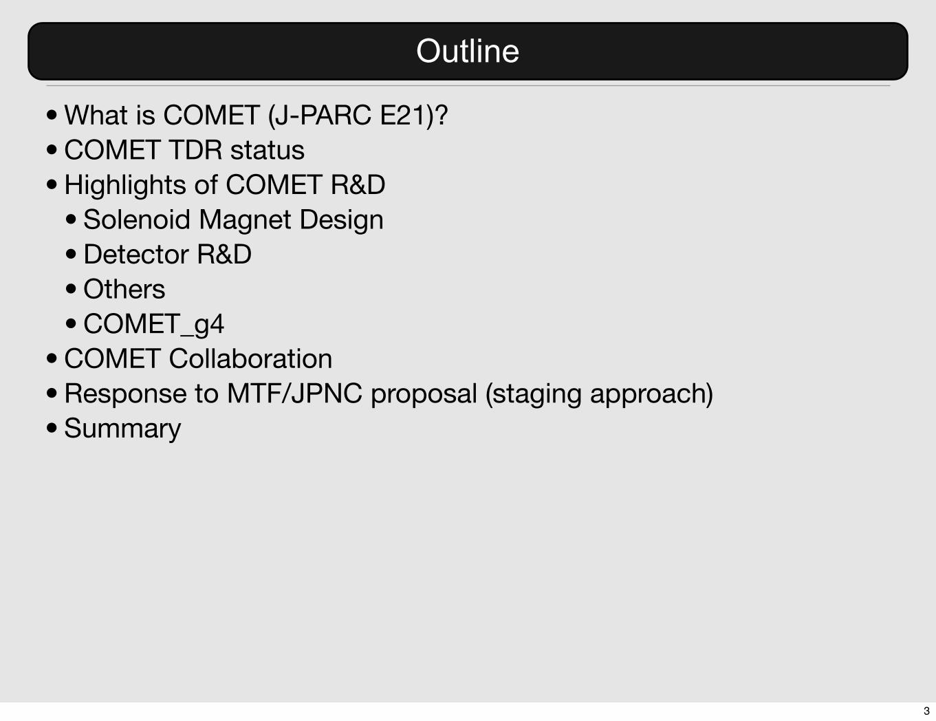
• What is COMET (J-PARC E21)?• COMET TDR status• Highlights of COMET R&D
• Solenoid Magnet Design• Detector R&D• Others• COMET_g4
• COMET Collaboration• Response to MTF/JPNC proposal (staging approach)• Summary
3

Resources shared between COMET and Mu2eWhat is COMET?
8GeV proton beam5T pion capture solenoid
3T muon transport(curved solenoids)
muon stoppingtarget
electron tracker and calorimeter
electron transport
B(µ� + Al⇥ e� + Al) = 3.3� 10�17
B(µ� + Al⇥ e� + Al) < 7� 10�17 (90%C.L.)
2.6
6
Experimental Goal of COMETJ-PARC E21
• 1011 muon stops/sec for 56 kW proton beam power.
• C-shape muon beam line and C-shape electron transport followed by electron detection system.
• Stage-1 approved from the J-PARC PAC in 2009.
10,000 improvement over the previous
4

COMET Technical Design Report (TDR)
5

Technical Design Reportfor
Experimental Search for Lepton Flavor Violating µ! ! e!
Conversion at Sensitivity of 10!16
with a Slow-Extracted Bunched Proton Beam(COMET)
J-PARC E21
January 13, 2012
Contents
1 Introduction 10
2 Physics Motivation 122.1 Introduction . . . . . . . . . . . . . . . . . . . . . . . . . . . . . . . . . . . . 12
2.1.1 History I — the establishment of the concept of lepton flavor . . . . 122.1.2 History II — the discovery of lepton flavor violation in neutrinos . . 13
2.2 New physics and µ!!e! conversion . . . . . . . . . . . . . . . . . . . . . . 142.3 Supersymmetric models . . . . . . . . . . . . . . . . . . . . . . . . . . . . . 15
2.3.1 General feature . . . . . . . . . . . . . . . . . . . . . . . . . . . . . . 152.3.2 Models with the seesaw mechanism . . . . . . . . . . . . . . . . . . . 16
2.4 Little Higgs models . . . . . . . . . . . . . . . . . . . . . . . . . . . . . . . . 172.5 Extra dimensional models . . . . . . . . . . . . . . . . . . . . . . . . . . . . 19
2.5.1 Anarchic Randall-Sundrum model . . . . . . . . . . . . . . . . . . . 192.5.2 UED models . . . . . . . . . . . . . . . . . . . . . . . . . . . . . . . 20
2.6 µ!!e! conversion at LHC era . . . . . . . . . . . . . . . . . . . . . . . . . 212.7 Phenomenology of µ!!e! conversion . . . . . . . . . . . . . . . . . . . . . . 22
2.7.1 What is a µ!!e! conversion process ? . . . . . . . . . . . . . . . . . 222.7.2 Signal and background events . . . . . . . . . . . . . . . . . . . . . . 222.7.3 µ!!e! conversion vs. µ+ " e+! . . . . . . . . . . . . . . . . . . . 23
2.8 Present experimental status . . . . . . . . . . . . . . . . . . . . . . . . . . . 232.8.1 µ!!e! conversion . . . . . . . . . . . . . . . . . . . . . . . . . . . . 23
2.8.1.1 SINDRUM-II . . . . . . . . . . . . . . . . . . . . . . . . . . 242.8.1.2 MECO . . . . . . . . . . . . . . . . . . . . . . . . . . . . . 252.8.1.3 Mu2e . . . . . . . . . . . . . . . . . . . . . . . . . . . . . . 25
2.8.2 µ+ " e+! Decay . . . . . . . . . . . . . . . . . . . . . . . . . . . . . 272.8.3 Why is µ!!e! conversion the next step ? . . . . . . . . . . . . . . . 27
3 Overview of COMET 293.1 Introduction to the COMET experiment . . . . . . . . . . . . . . . . . . . . 293.2 Advantages of the COMET experiment . . . . . . . . . . . . . . . . . . . . 31
4 Proton Beam 324.1 Requirement for proton beam . . . . . . . . . . . . . . . . . . . . . . . . . . 32
4.1.1 Proton energy . . . . . . . . . . . . . . . . . . . . . . . . . . . . . . . 324.1.2 Proton beam power . . . . . . . . . . . . . . . . . . . . . . . . . . . 334.1.3 Proton beam time structure . . . . . . . . . . . . . . . . . . . . . . . 33
4.2 Acceleration . . . . . . . . . . . . . . . . . . . . . . . . . . . . . . . . . . . . 34
4
COMET Technical Design Report (TDR)
COMET Technical Design Report (TDR) has been almost complete. It has already about 200 pages. Some highlights in TDR have been included in the progress report.
6

Technical Design Reportfor
Experimental Search for Lepton Flavor Violating µ! ! e!
Conversion at Sensitivity of 10!16
with a Slow-Extracted Bunched Proton Beam(COMET)
J-PARC E21
January 13, 2012
Contents
1 Introduction 10
2 Physics Motivation 122.1 Introduction . . . . . . . . . . . . . . . . . . . . . . . . . . . . . . . . . . . . 12
2.1.1 History I — the establishment of the concept of lepton flavor . . . . 122.1.2 History II — the discovery of lepton flavor violation in neutrinos . . 13
2.2 New physics and µ!!e! conversion . . . . . . . . . . . . . . . . . . . . . . 142.3 Supersymmetric models . . . . . . . . . . . . . . . . . . . . . . . . . . . . . 15
2.3.1 General feature . . . . . . . . . . . . . . . . . . . . . . . . . . . . . . 152.3.2 Models with the seesaw mechanism . . . . . . . . . . . . . . . . . . . 16
2.4 Little Higgs models . . . . . . . . . . . . . . . . . . . . . . . . . . . . . . . . 172.5 Extra dimensional models . . . . . . . . . . . . . . . . . . . . . . . . . . . . 19
2.5.1 Anarchic Randall-Sundrum model . . . . . . . . . . . . . . . . . . . 192.5.2 UED models . . . . . . . . . . . . . . . . . . . . . . . . . . . . . . . 20
2.6 µ!!e! conversion at LHC era . . . . . . . . . . . . . . . . . . . . . . . . . 212.7 Phenomenology of µ!!e! conversion . . . . . . . . . . . . . . . . . . . . . . 22
2.7.1 What is a µ!!e! conversion process ? . . . . . . . . . . . . . . . . . 222.7.2 Signal and background events . . . . . . . . . . . . . . . . . . . . . . 222.7.3 µ!!e! conversion vs. µ+ " e+! . . . . . . . . . . . . . . . . . . . 23
2.8 Present experimental status . . . . . . . . . . . . . . . . . . . . . . . . . . . 232.8.1 µ!!e! conversion . . . . . . . . . . . . . . . . . . . . . . . . . . . . 23
2.8.1.1 SINDRUM-II . . . . . . . . . . . . . . . . . . . . . . . . . . 242.8.1.2 MECO . . . . . . . . . . . . . . . . . . . . . . . . . . . . . 252.8.1.3 Mu2e . . . . . . . . . . . . . . . . . . . . . . . . . . . . . . 25
2.8.2 µ+ " e+! Decay . . . . . . . . . . . . . . . . . . . . . . . . . . . . . 272.8.3 Why is µ!!e! conversion the next step ? . . . . . . . . . . . . . . . 27
3 Overview of COMET 293.1 Introduction to the COMET experiment . . . . . . . . . . . . . . . . . . . . 293.2 Advantages of the COMET experiment . . . . . . . . . . . . . . . . . . . . 31
4 Proton Beam 324.1 Requirement for proton beam . . . . . . . . . . . . . . . . . . . . . . . . . . 32
4.1.1 Proton energy . . . . . . . . . . . . . . . . . . . . . . . . . . . . . . . 324.1.2 Proton beam power . . . . . . . . . . . . . . . . . . . . . . . . . . . 334.1.3 Proton beam time structure . . . . . . . . . . . . . . . . . . . . . . . 33
4.2 Acceleration . . . . . . . . . . . . . . . . . . . . . . . . . . . . . . . . . . . . 34
4
COMET Technical Design Report (TDR)
COMET Technical Design Report (TDR) has been almost complete. It has already about 200 pages. Some highlights in TDR have been included in the progress report.
Submit by the March J-PARC PAC
6

Highlights of COMET R&D
7

Superconducing Solenoid Magnets
8

DD KN31460-a
4 96 設計要項表 Design Data Sheet
全体形状
DD KN31460-a
6 96 設計要項表 Design Data Sheet
磁場プロファイル 磁場プロファイルの現段階での計算値を図2にまたその計算の元となるコイルパラメーターを表1に
示す。計算は空芯で行っているが実際のコイルは全て鉄ヨークの中に内包される鉄ヨーク付きでの磁場設計も設計検討の範囲とする。また図2の磁場はまだ完全には最適化されていない。 磁場の設計仕様はパイオン捕獲磁石の中心部で 5T以上の磁場を最大値として、ミューオン輸送ソレノイドでは3T、スペクトロメーターから検出器では 1T の磁場とする。パイオン捕獲磁石は、標的中心より 100mm上流に磁場ピークを持つこと。図2では空芯計算のためターゲット中心(z=0)で磁場ピークを持つが、鉄ヨークをかぶせることでピーク位置を z=-100mmとする。 ソレノイド磁場分布は、パイオン捕獲磁石の中心からスペクトロメーター(SS)にかけて単調減少で落
ちていく必要がある。このとき単調減少が要求されるのは、ダイポール磁場を持つ TS2,TS4,SSを除いた領域で、ソレノイド中心から半径 150mmの範囲を目標とする。(150mmの目標範囲が非常に困難な場合は別途協議の上、目標範囲を変更する可能性もある。) 図 3 に示すように捕獲ソレノイド内部には放射線シールドを設置する。このシールド内側の陽子標的より下流側の領域で要求された磁場分布を満たすよう、捕獲ソレノイドコイルおよびマッチングソレノイドコイルを分割する等、形状、配置を最適化すること。 ST1~ST3 のボア内には、ミューオン停止標的として多数のアルミ薄板(直径 200mm)を軸方向 800mmに渡って並べる。ミューオン停止標的の一番上流側で 2.4テスラ以上、最下流側で 1.90テスラ以下となるよう磁場勾配を持つこと。
図1.2.1 COMET Solenoid System 概要
Resources shared between COMET and Mu2eCOMET Magnet System
1) Pion capture solenoid (CS)2) Matching solenoid (MS)3) Muon transport solenoid (TS)4) Muon stopping target solenoid (ST)5) Spectrometer solenoid (SS)6) Detector Solenoid (DS)7) Correction dipole coils for TS and SS
9
DD KN31460-a
4 96 設計要項表 Design Data Sheet
全体形状
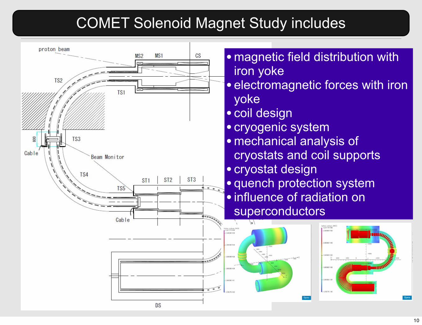
Resources shared between COMET and Mu2eCOMET Solenoid Magnet Study includes
• magnetic field distribution with iron yoke
• electromagnetic forces with iron yoke
• coil design • cryogenic system• mechanical analysis of
cryostats and coil supports• cryostat design• quench protection system• influence of radiation on
superconductors Return yoke
� Iron yoke covers from end to end� Thickness of iron is optimized
10

Resources shared between COMET and Mu2eAl-stabilized SC magnet R&D
Superconductor R&D� US-Japan collaboration on Al-stabilized
superconductor R&D� In JFY2009
� Replicate aluminum conforming technology� Confirm yield strength of aluminum with various
additives� Successful trial production of 200 meter cable
� 15mmx4.7mm (COMET design)� In JFY2010
� Test of RIKEN test coil in FNAL� Test of ATLAS short sample stack in FNAL� Trial production of larger conductor
� 30mmx6.5mm (Mu2e design)� In JFY2011
� Plan to fabricate a test coil with 15mmx4.7mm conductor in FNAL� small diamter
� Plan to fabricate a test coil with 30mmx6.5mm conductor in Japan� 1.3 m diameter� radiation hard insulator
Design values:� Size: 4.7x15mm� Offset yield point of
Al@4K: >85MPa� RRR@0T: >500� Al/Cu/SC: 7.3/0.9/1� 14 SC strands: 1.15mm
dia.
•Two kinds of SC wire with Al stabilizer•15mm x 4.7mm•30mm x 6.63mm•Coil winding in Japanese manufacturer•Testing bending procedure to form a coil•Glass-Kapton prepreg as insulator•BT resin or Epoxy•Completed by the end of March•Excitation test at FNAL•as a part of US-Japan program
Bending Tests of a Wide Conductor at Toshiba (ATLAS cable)
No problem was found in R=650No problem was found in R=650
cryostat at NHMFL,shipped to FNAL
11

[email protected] 20 PASI Fermilab January 2012
Superconducting Solenoid R&DNeutron irradiation tests performed at KURRI reactor, Kyoto University
2 Days
Demonstrated that Al stabiliser tolerates COMET
radiation environment
Resources shared between COMET and Mu2eIrradiation Test at KURRI reactor
Demonstrated that Al stabilizer tolerates COMET radiation environment.
12

Detector R&D
13

[email protected] 16 PASI Fermilab January 2012
COMET Detector Section
● Straw-tube electron tracker in 1 Tesla field
● 800 kHz charged particle and 8 MHz gamma rates
● 0.4% momentum and 700 micron spatial resolution required
COMET Detector SectionStraw-Tube Tracker
•Straw-tube electron tracker in vaccum under 1 T magnetic field•800 kHz charged particles and 8 MHz gamma rate per plane•0.4 % momentum resolution and 700 micron spacial resolution
14

✤ Straw Chamber Overview - cont’d7
Hajime NISHIGUCHI (KEK) “Straw Tracker R&D at KEK” COMET CM7, Osaka U., 9-10.Jan.2012
✤ Concept4
Hajime NISHIGUCHI (KEK) “Straw Tracker R&D at KEK” COMET CM7, Osaka U., 9-10.Jan.2012
Gas Inlet
Signal
Evacuation
HV Line
Straw Chamber(1m)
Gas Manifold
Vacuum Chamber
Preamps Gas Outlet
✤ Inserting ...11
Hajime NISHIGUCHI (KEK) “Straw Tracker R&D at KEK” COMET CM7, Osaka U., 9-10.Jan.2012
Resources shared between COMET and Mu2eStraw Gas Chamber R&D (1)
• Prototyping of straw chambers• Construction of a vacuum
chamber• Gas manifold and front-end
electronics in place.
Tests of Straw chambersin vacuum
15

Straw Chamber R&D at KEK(Study Detail)H.Nakai,Osaka-U CM7
Raw Signal
htdc19Entries 1612
Mean 4.162e+04
RMS 24.56
Underflow 0
Overflow 0
Integral 1612
0 20 40 60 80 100 120 140310×0
100
200
300
400
500
600
700
800
900
htdc19Entries 1612
Mean 4.162e+04
RMS 24.56
Underflow 0
Overflow 0
Integral 1612
htdc19htdc20
Entries 1385
Mean 4.904e+04
RMS 1.066e+04
Underflow 0
Overflow 0
Integral 1385
0 20 40 60 80 100 120 140310×0
1
2
3
4
5
6
7htdc20
Entries 1385
Mean 4.904e+04
RMS 1.066e+04
Underflow 0
Overflow 0
Integral 1385
htdc20
htdc21Entries 1360
Mean 4.683e+04
RMS 1.082e+04
Underflow 0
Overflow 0
Integral 1360
0 20 40 60 80 100 120 140310×0
2
4
6
8
10htdc21
Entries 1360
Mean 4.683e+04
RMS 1.082e+04
Underflow 0
Overflow 0
Integral 1360
htdc21htdc22
Entries 506
Mean 4.526e+04
RMS 1.189e+04
Underflow 0
Overflow 0
Integral 506
0 20 40 60 80 100 120 140310×0
1
2
3
4
5
6htdc22
Entries 506
Mean 4.526e+04
RMS 1.189e+04
Underflow 0
Overflow 0
Integral 506
htdc22
hqdc21Entries 1612Mean 321RMS 59.4Underflow 0Overflow 0Integral 1612
0 500 1000 1500 2000 2500 3000 3500 40000
2
4
6
8
10
12
14
16
18hqdc21
Entries 1612Mean 321RMS 59.4Underflow 0Overflow 0Integral 1612
hqdc21hqdc23
Entries 1612Mean 510.8RMS 189.5Underflow 0Overflow 0Integral 1612
0 500 1000 1500 2000 2500 3000 3500 40000
2
4
6
8
10
12
14
16
18
20
22 hqdc23Entries 1612Mean 510.8RMS 189.5Underflow 0Overflow 0Integral 1612
hqdc23
hqdc25Entries 1612Mean 626.8RMS 159.1Underflow 0Overflow 0Integral 1612
0 500 1000 1500 2000 2500 3000 3500 40000
2
4
6
8
10
12
14
16
hqdc25Entries 1612Mean 626.8RMS 159.1Underflow 0Overflow 0Integral 1612
hqdc25hqdc27
Entries 1612Mean 585.2RMS 203.3Underflow 0Overflow 0Integral 1612
0 500 1000 1500 2000 2500 3000 3500 40000
2
4
6
8
10
12
14
16hqdc27
Entries 1612Mean 585.2RMS 203.3Underflow 0Overflow 0Integral 1612
hqdc27
QDC(very preliminary) TDC(very preliminary)
DAQ
Raw Signal
psec
180 nsec
8 mV
46 4 STATUS OF DETECTOR R&D
Figure 54: Capacitive sensors used for deformation study.
Figure 55: Capacitive sensors mounted on the prototype for deformation study.
4.2 Front-end Electronics R&D
As described in CDR[2], the front-end electronics equipped on the detector will includereadout digitization electronics for reducing the substantial cable volume and signal degra-dation during transmission through long cables. The readout system will be designed totake advantage of modern electronic design using distributed signal processing [8]. All sig-nals are digitized at the front end, and stored in digital pipelines for trigger latency. Oncea trigger is presented, only those channels having signals above a set threshold are read,stored in bu!ers, and then serially transferred to a data acquisition system outside thevacuum wall. At this point the events are rebuilt, analyzed, filtered, and finally committedto permanent storage.
Based on this thought, we started prototyping of the front-end electronics. A blockdiagram of the prototype is shown in Figure 58.
4.1 Strawtube Tracker R&D 45✤ Straw Chamber Overview - cont’d7
Hajime NISHIGUCHI (KEK) “Straw Tracker R&D at KEK” COMET CM7, Osaka U., 9-10.Jan.2012
✤ Gas Manifold - cont’d10
Hajime NISHIGUCHI (KEK) “Straw Tracker R&D at KEK” COMET CM7, Osaka U., 9-10.Jan.2012
Mode - A Mode - B
Front-End Electronics is placed in a manifold
Front-End Electronics is placed in vacuum
(outside manifold)
Figure 52: Strawtube tracker prototype.
Figure 53: Strawtube vacuum chamber containing the prototype.
in the COMET final detector. This is su!ciently small compared to a pumping power forthe inner volume of the detector solenoid.
Operation of the prototype as a drift chamber has just commenced. Figure 57 showsobserved charge (upper) and drift time (lower) distributions observed on wires on the up-per (left) and lower (right) layers. Detailed studies such as optimization of the operationvoltage and gas mixture, and rate dependence of the detector response will continue towardfinalization of the detector performance evaluation.
Resources shared between COMET and Mu2eStraw Gas Chamber R&D (2)
• Normal operation in air• X-t relation and spatial resolution
• Gas leak study• Over-pressurized study
• 2 atom.• Deformation study
• capacitive sensor• Operation in vacuum
• just started...
Tests of Straw chambersin vacuum
Raw signal without amp.
Deformation study by capacitive sensor
front-end electronicsin a manifold
16

Resources shared between COMET and Mu2eFrontend Electronics R&D
Front-‐end:ASDGiga bit Ether
FPGA
Analog memory:DRS4
Signal fromstraw tube12cm
17cm
16ch/1board
• Front-end electronics for straw trackers and crystal calorimeter. • wave-form sampling based on switched capacitor array (DRS4)• a prototype board is constructed and tested with the KEK
electronics group.
17

COMET Detector SectionCrystal Calorimeter
•Energy and position measurements, PID, trigger signal•5% energy and 1 cm spatial resolution at 100 MeV
[email protected] 18 PASI Fermilab January 2012
COMET Detector Section
● Crystal calorimeter
● for energy and position measurement, PID, trigger signal
● 5% energy and 1cm spatial resolution at 100 MeV
18

50 x GSO(Ce) (20x20x120mm3 by Hitachi Chemi.)
9 x LYSO (20x20x150mm3 by Dubna (Saint-Gobain))
Pream
ps
for 50ch(Yuri’s circuit)
Waveform
digitizer
(ex. CA
EN
V1742)
DA
Q P
C(M
IDA
S)
with APD ( and light guide)
and wrapping
Logger
Th
erm
isto
rs
HV
PSDC
5V
Pream
ps
for 9ch(Yuri’s circuit)
Th
erm
.
Trigger Scinti.
Trigger Scinti. for CR
The detail was shown in the Dima’s talk.
h1Entries 35748Mean 6.622e+04RMS 2.842e+04Underflow 0Overflow 3
ns)!par[3] (ch 0 50 100 150 200 250 300 350 400
310!
(cou
nts)
1
10
210
h1Entries 35748Mean 6.622e+04RMS 2.842e+04Underflow 0Overflow 3
run1121:par[3]
6.1MeV
2.6MeV
Resources shared between COMET and Mu2eElectron Calorimeter R&D
Calorimeter Prototyping R&D
[email protected] 19 PASI Fermilab January 2012
Calorimeter R&D● GSO / LYSO crystals with APDs tested 2011
● Vertical slice tests this year
● Design being finalised for 50-
crystal / APD prototype
● beam tests later this year at
BINP Novisibirsk
LaBr3
LYSO• Single crystal test has been done at BINP.
• Prototypes for GSO and LYSO crystal array are planned.
• Beam tests at BINP in summer and winter, 2012.
typical spectrum for LYSO and APD (10x10 mm2)
19

8 2 COSMIC RAY SHIELDING DESIGN
The fibers are mirrored at the rear end; the scintillation light is read out at the other endwith a Silicon Photomultpliers with a 1.3! 1.3 mm2 active area. We consider two possibletypes of SiPM; MPPC from Hamamatsu Photonics [4] and Russian made MRS APD [5](see Figure 6). The SiPM, either of MPPC or MRS APD, is mounted on a strip with aspecial plastic connector that fixes its position and guarantees a small air gap to the fiberas shown in Figyre 7.
YHU\KLJKHIILFLHQF\HYHQZLWKDKLJKOHYHOWKUHVKR
Figure 6: View of 796 pixel MRS APD fiber (CPTA, Russia).
The proposed strip design has the following advantages over a wider strip with severalWLS fibers:
• Light from a MIP is not shared between di!erent SiPMs. This allows to have a veryhigh e"ciency even with a high level threshold. Our measurements demonstrate thatthe e"ciency for MIP for the worst case of particle crossing far end of the strip islarger than 99 % with a threshold at 7 pixels equivalent (see Figure 8). As it will beshown below at such threshold the MPPC noise is less than 10 Hz, i.e. is below therate of cosmic rays. Dependence of the strip light yield to MIP versus the distance tophoto-detector is shown in Figure 9. Fig.ure 10 shows the SiPM noise rate distributionwith a 7 pixels threshold for more than 200 Hamamatsu MPPCs.
• It is easier to estimate the e"ciency of each strip with cosmic muons using coincidenceswith other strip signals.
• In case of problems with one channel only a small part of the detector is a!ected.
• Time resolution of about 1 nsec can be achieved easily.
For each module SiPMs are read out by 15 channels of di!erential preamplifiers (seeFigure 11), that allows to transfer the signals over a large distance. This preamplifier hasbeen tested; a compact 15 channel layout will be developed soon.
Resources shared between COMET and Mu2eR&D on Cosmic Ray Veto System
• The active cosmic ray veto system is based on plastic scintillator with fiber readout.
• Photosensors are MRS APD or MPPC.• Designed by the BINP (Novosibirsk) and ITEP
(Moscow) groups.• Strip 0.7x4x300 cm3 scintillator made by
Uniplast (Russia).• The light yield at a far end is even 15 pe. The
counter efficiency for MIP is 99.7% with 55 pixel threshold.
796 pixel MRS APD fiber (CPTA, Russia).
20

• To monitor a number of stopping muons, muonic X-rays from the muon stopping target (made of aluminum) is to be measured.
• Two different detectors, Ge and CdTe were tested at the J-PARC MLF muon facilities in fall, 2010.
• Detector efficiencies and transition rates are studied.
• R&D on Multi-pixel detectors is being done.
• Location of the muonic X-ray detectors at COMET is being studied.
Ge detector’s Result - Al target
Measuring time: 216minMuon momentum:10-16 MeV/c(decay muon)
20
CdTe detector
EURORAD,Ohmic type10mm×10mm×3mm
Ge detector
Ortec,POPTOPtype,GMXφ=50mm,length=50mm
X-ray detectors at Beam test
15
Theoretical predictions muonic X-ray energy(kev)
(emission rate)
CdTe detector’s Result - Al target
Kα Kβ Kγ Lα Lβ Lγ
C 75keV(0.604)
89keV(0.102)
94keV(0.083) - - -
N 102keV(0.763)
122keV(0.067)
128keV(0.029) - - -
O 134keV(0.735)
159keV(0.070)
168keV(0.030) - - -
Al 347keV(0.811)413keV(0.058)
436keV(0.019)
66keV(0.422)
89keV(0.072)
100keV(0.031)
Fit function
Al-Lα & C-Kα
Al-Kα
19
Resources shared between COMET and Mu2eR&D on Muon Monitor System
Measured muonic X-rays from aluminum21

COMET_G4
22

Resources shared between COMET and Mu2eCOMET_G4 (Geant Simulation)
[email protected] 14 COMET Collaboration Meeting January 2012
Full Field Map and Geometry Alignment
mm
mmT
[email protected] 4 PASI Fermilab January 2012
Before Stopping Target
{20 0 20
y [cm]
y [cm]
{20 0 20 x [cm]
20
0
{20
20
0
{20
Ben Krikler
after collimation of
high-momentum
muons
at muon stopping [email protected] 2 PASI Fermilab January 2012
Fluxes at Entrance to Curved Solenoid
{20 0 20
y [cm]
y [cm]
{20 0 20 x [cm]
Ben Krikler
20
0
{20
20
0
{20
at [email protected] 3 PASI Fermilab January 2012
After 90 Degrees of Curved Solenoid
{20 0 20
y [cm]
y [cm]
{20 0 20 x [cm]
20
0
{20
20
0
{20
Ben Krikler
3 T solenoid
field,
0.018 T
dipole field
(tunable)
at 90 degree bending
•Full 3D field mapping (from Toshiba) is introduced.
•Mass data production has been made.
23

COMET Collaboration
24

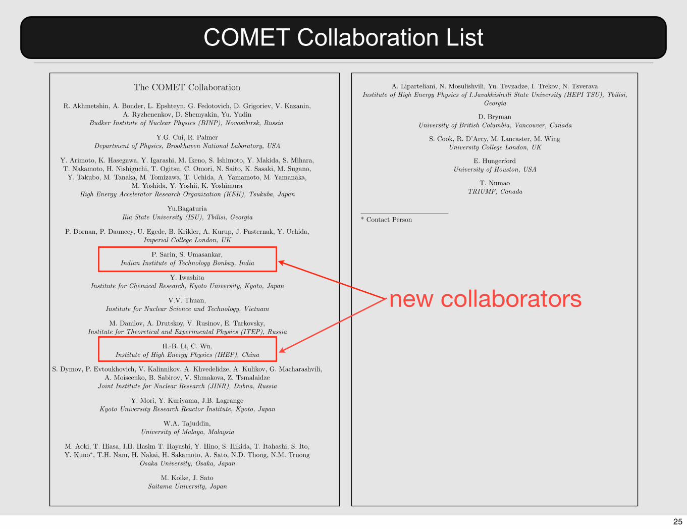
Resources shared between COMET and Mu2eCOMET Collaboration List2
The COMET Collaboration
R. Akhmetshin, A. Bonder, L. Epshteyn, G. Fedotovich, D. Grigoriev, V. Kazanin,A. Ryzhenenkov, D. Shemyakin, Yu. Yudin
Budker Institute of Nuclear Physics (BINP), Novosibirsk, Russia
Y.G. Cui, R. PalmerDepartment of Physics, Brookhaven National Laboratory, USA
Y. Arimoto, K. Hasegawa, Y. Igarashi, M. Ikeno, S. Ishimoto, Y. Makida, S. Mihara,T. Nakamoto, H. Nishiguchi, T. Ogitsu, C. Omori, N. Saito, K. Sasaki, M. Sugano,Y. Takubo, M. Tanaka, M. Tomizawa, T. Uchida, A. Yamamoto, M. Yamanaka,
M. Yoshida, Y. Yoshii, K. YoshimuraHigh Energy Accelerator Research Organization (KEK), Tsukuba, Japan
Yu.BagaturiaIlia State University (ISU), Tbilisi, Georgia
P. Dornan, P. Dauncey, U. Egede, B. Krikler, A. Kurup, J. Pasternak, Y. Uchida,Imperial College London, UK
P. Sarin, S. Umasankar,Indian Institute of Technology Bonbay, India
Y. IwashitaInstitute for Chemical Research, Kyoto University, Kyoto, Japan
V.V. Thuan,Institute for Nuclear Science and Technology, Vietnam
M. Danilov, A. Drutskoy, V. Rusinov, E. Tarkovsky,Institute for Theoretical and Experimental Physics (ITEP), Russia
H.-B. Li, C. Wu,Institute of High Energy Physics (IHEP), China
S. Dymov, P. Evtoukhovich, V. Kalinnikov, A. Khvedelidze, A. Kulikov, G. Macharashvili,A. Moiseenko, B. Sabirov, V. Shmakova, Z. Tsmalaidze
Joint Institute for Nuclear Research (JINR), Dubna, Russia
Y. Mori, Y. Kuriyama, J.B. LagrangeKyoto University Research Reactor Institute, Kyoto, Japan
W.A. Tajuddin,University of Malaya, Malaysia
M. Aoki, T. Hiasa, I.H. Hasim T. Hayashi, Y. Hino, S. Hikida, T. Itahashi, S. Ito,Y. Kuno!, T.H. Nam, H. Nakai, H. Sakamoto, A. Sato, N.D. Thong, N.M. Truong
Osaka University, Osaka, Japan
M. Koike, J. SatoSaitama University, Japan
3
A. Liparteliani, N. Mosulishvili, Yu. Tevzadze, I. Trekov, N. TsveravaInstitute of High Energy Physics of I.Javakhishvili State University (HEPI TSU), Tbilisi,
Georgia
D. BrymanUniversity of British Columbia, Vancouver, Canada
S. Cook, R. D’Arcy, M. Lancaster, M. WingUniversity College London, UK
E. HungerfordUniversity of Houston, USA
T. NumaoTRIUMF, Canada
* Contact Person
25
Resources shared between COMET and Mu2eCOMET Collaboration List2
The COMET Collaboration
R. Akhmetshin, A. Bonder, L. Epshteyn, G. Fedotovich, D. Grigoriev, V. Kazanin,A. Ryzhenenkov, D. Shemyakin, Yu. Yudin
Budker Institute of Nuclear Physics (BINP), Novosibirsk, Russia
Y.G. Cui, R. PalmerDepartment of Physics, Brookhaven National Laboratory, USA
Y. Arimoto, K. Hasegawa, Y. Igarashi, M. Ikeno, S. Ishimoto, Y. Makida, S. Mihara,T. Nakamoto, H. Nishiguchi, T. Ogitsu, C. Omori, N. Saito, K. Sasaki, M. Sugano,Y. Takubo, M. Tanaka, M. Tomizawa, T. Uchida, A. Yamamoto, M. Yamanaka,
M. Yoshida, Y. Yoshii, K. YoshimuraHigh Energy Accelerator Research Organization (KEK), Tsukuba, Japan
Yu.BagaturiaIlia State University (ISU), Tbilisi, Georgia
P. Dornan, P. Dauncey, U. Egede, B. Krikler, A. Kurup, J. Pasternak, Y. Uchida,Imperial College London, UK
P. Sarin, S. Umasankar,Indian Institute of Technology Bonbay, India
Y. IwashitaInstitute for Chemical Research, Kyoto University, Kyoto, Japan
V.V. Thuan,Institute for Nuclear Science and Technology, Vietnam
M. Danilov, A. Drutskoy, V. Rusinov, E. Tarkovsky,Institute for Theoretical and Experimental Physics (ITEP), Russia
H.-B. Li, C. Wu,Institute of High Energy Physics (IHEP), China
S. Dymov, P. Evtoukhovich, V. Kalinnikov, A. Khvedelidze, A. Kulikov, G. Macharashvili,A. Moiseenko, B. Sabirov, V. Shmakova, Z. Tsmalaidze
Joint Institute for Nuclear Research (JINR), Dubna, Russia
Y. Mori, Y. Kuriyama, J.B. LagrangeKyoto University Research Reactor Institute, Kyoto, Japan
W.A. Tajuddin,University of Malaya, Malaysia
M. Aoki, T. Hiasa, I.H. Hasim T. Hayashi, Y. Hino, S. Hikida, T. Itahashi, S. Ito,Y. Kuno!, T.H. Nam, H. Nakai, H. Sakamoto, A. Sato, N.D. Thong, N.M. Truong
Osaka University, Osaka, Japan
M. Koike, J. SatoSaitama University, Japan
3
A. Liparteliani, N. Mosulishvili, Yu. Tevzadze, I. Trekov, N. TsveravaInstitute of High Energy Physics of I.Javakhishvili State University (HEPI TSU), Tbilisi,
Georgia
D. BrymanUniversity of British Columbia, Vancouver, Canada
S. Cook, R. D’Arcy, M. Lancaster, M. WingUniversity College London, UK
E. HungerfordUniversity of Houston, USA
T. NumaoTRIUMF, Canada
* Contact Person
new collaborators
25

Resources shared between COMET and Mu2eCOMET Collaboration List2
The COMET Collaboration
R. Akhmetshin, A. Bonder, L. Epshteyn, G. Fedotovich, D. Grigoriev, V. Kazanin,A. Ryzhenenkov, D. Shemyakin, Yu. Yudin
Budker Institute of Nuclear Physics (BINP), Novosibirsk, Russia
Y.G. Cui, R. PalmerDepartment of Physics, Brookhaven National Laboratory, USA
Y. Arimoto, K. Hasegawa, Y. Igarashi, M. Ikeno, S. Ishimoto, Y. Makida, S. Mihara,T. Nakamoto, H. Nishiguchi, T. Ogitsu, C. Omori, N. Saito, K. Sasaki, M. Sugano,Y. Takubo, M. Tanaka, M. Tomizawa, T. Uchida, A. Yamamoto, M. Yamanaka,
M. Yoshida, Y. Yoshii, K. YoshimuraHigh Energy Accelerator Research Organization (KEK), Tsukuba, Japan
Yu.BagaturiaIlia State University (ISU), Tbilisi, Georgia
P. Dornan, P. Dauncey, U. Egede, B. Krikler, A. Kurup, J. Pasternak, Y. Uchida,Imperial College London, UK
P. Sarin, S. Umasankar,Indian Institute of Technology Bonbay, India
Y. IwashitaInstitute for Chemical Research, Kyoto University, Kyoto, Japan
V.V. Thuan,Institute for Nuclear Science and Technology, Vietnam
M. Danilov, A. Drutskoy, V. Rusinov, E. Tarkovsky,Institute for Theoretical and Experimental Physics (ITEP), Russia
H.-B. Li, C. Wu,Institute of High Energy Physics (IHEP), China
S. Dymov, P. Evtoukhovich, V. Kalinnikov, A. Khvedelidze, A. Kulikov, G. Macharashvili,A. Moiseenko, B. Sabirov, V. Shmakova, Z. Tsmalaidze
Joint Institute for Nuclear Research (JINR), Dubna, Russia
Y. Mori, Y. Kuriyama, J.B. LagrangeKyoto University Research Reactor Institute, Kyoto, Japan
W.A. Tajuddin,University of Malaya, Malaysia
M. Aoki, T. Hiasa, I.H. Hasim T. Hayashi, Y. Hino, S. Hikida, T. Itahashi, S. Ito,Y. Kuno!, T.H. Nam, H. Nakai, H. Sakamoto, A. Sato, N.D. Thong, N.M. Truong
Osaka University, Osaka, Japan
M. Koike, J. SatoSaitama University, Japan
3
A. Liparteliani, N. Mosulishvili, Yu. Tevzadze, I. Trekov, N. TsveravaInstitute of High Energy Physics of I.Javakhishvili State University (HEPI TSU), Tbilisi,
Georgia
D. BrymanUniversity of British Columbia, Vancouver, Canada
S. Cook, R. D’Arcy, M. Lancaster, M. WingUniversity College London, UK
E. HungerfordUniversity of Houston, USA
T. NumaoTRIUMF, Canada
* Contact Person
new collaborators
COMET was approved as a project at JINR in 2011.
25

Resources shared between COMET and Mu2eCOMET Organization
• The “COMET Constitution” has been written and agreed. • The COMET organization is defined.• The COMET organization will be formed and started in the next
collaboration meeting.
spokesperson project manager@KEK
EditorialBoard
SpeakerBureau
Executive Board
Collaboration Board
COMET Organization
26

On MTF Proposal (COMET Staging Plan)
27

Beam line plan at southern area
with COMET beam line
Resources shared between COMET and Mu2eMTF Proposal on COMET Beam Line
• MTF and JPNC’s proposal on the beam lines at the south area.
from Tanaka-san’s slides in this J-PARC PAC.28

Beam line plan at southern area
with COMET beam line
Resources shared between COMET and Mu2eMTF Proposal on COMET Beam Line
• MTF and JPNC’s proposal on the beam lines at the south area.
from Tanaka-san’s slides in this J-PARC PAC.28

Resources shared between COMET and Mu2eCOMET Muon Beam Line
COMET wishes to have the first 90 degrees of the muon transport curved solenoids (which are located inside concrete shields) in this proposal, since the installation of these magnets would become difficult after activation by a proton beam.
up to here29

Resources shared between COMET and Mu2eCOMET Staging Plan
COMET Phase-I
30

Resources shared between COMET and Mu2eCOMET Staging Plan
(1) Study for the COMET full experiment•Measurement of secondary particle production•Measurements of muon yield, •Measurements of backgrounds from pions, electrons, neutrons,
kaons, and anti-protons.•Muon beam tuning
COMET Phase-I
Page 4
Background Working Group Status
COMET Collaboration Meeting 7 9th January 2012 Ajit Kurup
CDR
Background estimation in CDR30

Resources shared between COMET and Mu2eCOMET Staging Plan
(1) Study for the COMET full experiment•Measurement of secondary particle production•Measurements of muon yield, •Measurements of backgrounds from pions, electrons, neutrons,
kaons, and anti-protons.•Muon beam tuning
(2) Physics experiments• µ-+ N →e- + N conversion• µ-+ N →e+ + N conversion• µ-+ e- →e- + e-
COMET Phase-I
1
10
102
103
80 90 100eve
nts
/ c
ha
nn
el
Class 1 events: prompt forward removed
µe simulation
MIO simulation
e+ measurement
e- measurement
1
10
80 90 100
Class 2 events: prompt forward
momentum (MeV/c)
SINDRUM II
configura
tion 2
000
1m
A
B
CD ED
F
G
H
H
I
J
A
B
C
D
E
F
G
H
I
J
exit beam solenoid
gold target
vacuum wall
scintillator hodoscope
Cerenkov hodoscope
inner drift chamber
outer drift chamber
superconducting coil
helium bath
magnet yokeSINDRUM II
Final result on mu - e conversion on Gold
target is being prepared for publication
< 7 x 10-13 90%CL
@ PSI
Detector is being studied.Its cost can mostly be covered by
the COMET collaboration.31

Resources shared between COMET and Mu2eCOMET Staging Plan
(1) Study for the COMET full experiment•Measurement of secondary particle production•Measurements of muon yield, •Measurements of backgrounds from pions, electrons, neutrons,
kaons, and anti-protons.•Muon beam tuning
(2) Physics experiments• µ-+ N →e- + N conversion• µ-+ N →e+ + N conversion• µ-+ e- →e- + e-
COMET Phase-I
1
10
102
103
80 90 100eve
nts
/ c
ha
nn
el
Class 1 events: prompt forward removed
µe simulation
MIO simulation
e+ measurement
e- measurement
1
10
80 90 100
Class 2 events: prompt forward
momentum (MeV/c)
SINDRUM II
configura
tion 2
000
1m
A
B
CD ED
F
G
H
H
I
J
A
B
C
D
E
F
G
H
I
J
exit beam solenoid
gold target
vacuum wall
scintillator hodoscope
Cerenkov hodoscope
inner drift chamber
outer drift chamber
superconducting coil
helium bath
magnet yokeSINDRUM II
Final result on mu - e conversion on Gold
target is being prepared for publication
< 7 x 10-13 90%CL
@ PSI
plan to submit a LOI for the July PAC. Detector is being studied.
Its cost can mostly be covered by the COMET collaboration.
31

Summary
33

Summary
34

Summary
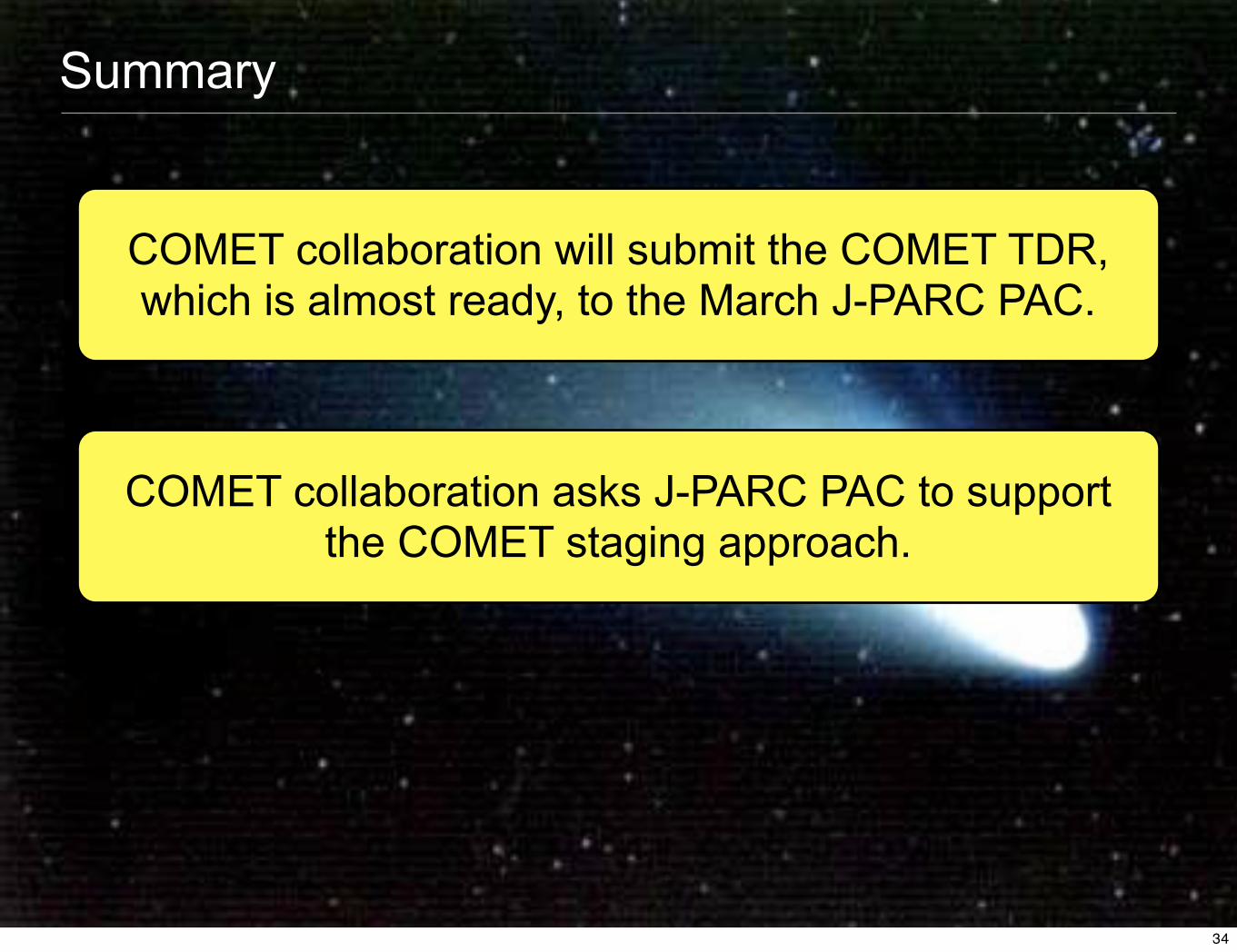
COMET collaboration will submit the COMET TDR, which is almost ready, to the March J-PARC PAC.
34
Summary
COMET collaboration will submit the COMET TDR, which is almost ready, to the March J-PARC PAC.
COMET collaboration asks J-PARC PAC to supportthe COMET staging approach.
34

Summary
COMET collaboration will submit the COMET TDR, which is almost ready, to the March J-PARC PAC.
COMET collaboration asks J-PARC PAC to supportthe COMET staging approach.
COMET collaboration will submit a LOI of COMET Phase-I to the July J-PARC PAC.
34


