21
PluraSens ® Methane Detector-Transmitter E2608-CH4 User Manual

PluraSens®
Methane Detector-Transmitter
E2608-CH4
User Manual

E2608-CH4 Rev 21.06.2021
Table of contentsMethane 3
Specifications 4
Product description 6
Safety requirements 6
Operating conditions 6
Installation guidelines 7Wall mount version 7Duct mount version 7
Mounting dimensions 8
Sensor probe handling 9
Gas sensor replacement procedures 9
Electrical connections 10Correct and incorrect cabling for 24 VAC 12
Operation 13
Maintenance 13
Calibration 13
Delivery set 14Order code for E2608-CH4 options 14
Configuring 15
Return to default settings 15
Modbus RTU Communication 16RS485 communication interface 16Communication parameters 16
Modbus holding registers 16
Warranty 21
Manufacturer contacts 21
2

E2608-CH4 Rev 21.06.2021
Methane
Colorless flammable gas, widely used as a fuel.
Synonyms: Marsh Gas, Natural Gas, Carbon tetrahydride, Hydrogen carbide
Chemical formula CH4
Molar weight 16
Relative gas density (to air) 0.55
Conversion 1 ppm = 0.65 mg/m3
Boiling point −161.49 °C
Low explosive limit (LEL), % vol. in air 5.0
Upper explosive limit (UEL), % vol. in air 15
Odor Odorless when pure. Methane used in the kitchenscontains an odorant
Hazards Highly flammable, mixtures with air are explosive.Asphyxiant.
Exposure limits not established
Conversion of ppm to mg/m3 is calculated for 25°C and 1 atm.
3

E2608-CH4 Rev 21.06.2021
Specifications
Sampling method Diffusion
Sensor type Metal oxide semiconductor Catalytic (pellistor)
Typical detection range 0...100% LEL 0...100% LEL
Resolution / digital unit 0.1% LEL 1% LEL
Response time T90 ca. 60 s ≤10s
Sensor lifetime > 5 years > 5 years
Calibration interval 12 months 6 months
Operating conditions
-40...+70 °C -40...+70°C
<95% RH non-condensing, 0,9...1,1 atm;Explosion safe indoor areas
Normal ambient oxygen levelAvoid strong mechanical shock, vibrations, or EMI
Avoid exposure to corrosive gases or silicone-containing products
Signal update Every 1 second
Power supply 11...30 VDC,24 VAC or 90...265 VAC as options
Power consumption < 2 VA
Load resistance RL < (Us - 2 V) / 22 mA for 4-20 mARL > 250 kOhm for 0-10 V mode
Digital interface RS485, Modbus RTU protocolNo galvanic isolation
Analog outputs 2 × 4-20 mA / 0-10 V, user settable
Outputs assignment OUT1: Gas; OUT2: Gas
Output scale width > 10 × resolutionRecommended: 20-100% of the detection range
Relay outputs 2 × SPST, max 5 A, 30 VDC / 250 VAC
Default alarm setpoints RE1 (LOW): set 20% LEL; release 16% LELRE2 (HIGH): set 50% LEL; release 40% LEL
Cable connections Screwless spring-loaded terminals
Enclosure Light beige ABS, wall mount, protection class IP65
Dimensions H87 × W82 × D55 mm
CE marking According to 2014/30/EU and 2014/35/EU, EN 50491-4-1:2012
4

E2608-CH4 Rev 21.06.2021
EN61000-6-3:2020, EN 61326-1:2013(EMC, emissions)EN 61000-6-1:2019, EN 61000-6-2:2019(EMC, Immunity)
EN 60079-29-1:2016, EN 60079-29-2:2015 and EN 60079-29-3:2014
Other options
Remote probe Protection IP65, default cable length 3.0 m;max height 80 mm, max diameter 65 mm
5

E2608-CH4 Rev 21.06.2021
Product description
E2608 series detectors-transmitters belong to the PluraSens® family of multifunctionalmeasurement instruments. The instruments utilize gas sensors of various types withexcellent repeatability, stability, and long lifetime.
E2608 series provides two independent analog outputs OUT1 and OUT2, user-selectable to4-20 mA or 0-10 V. RS485 Modbus RTU digital communication interface allows easyinstrument configuration and integration into various automation systems.
Two relays RE1 and RE2 with closing dry contacts can be used to switch alarm sirens,ventilation fans, shut-off valves, or other actuators. Remote probe, duct mount version, and24 VAC or 230 VAC power supply options are available.
The version of your detector-transmitter is marked on the package. If the symbol ⚠ ismarked on the equipment, consult the documentation for further information.
Safety requirements
Misuse will impair the protection of the product. Always adhere to the safety provisionsapplicable in the country of use.
Do not perform any maintenance operation with the power on. Do not let water or foreignobjects inside the device.
Removal of the PCB from the enclosure voids the warranty. Do not touch the electroniccomponents directly, as they are sensitive to static electricity.
Connection diagrams can be found in the electrical connections section. The device mightnot perform correctly or be damaged if the wrong power supply is connected.
External circuits connected to the equipment should have sufficient insulation ratingaccording to the environmental conditions and equipment power.
A disconnecting device that is marked as such and easily accessible should be included inthe installation of this product.
Operating conditions
The device should be used both in a non-hazardous area and in a basic electromagneticenvironment, where the latter is defined in EN 61326-1. Avoid strong mechanical shock andvibrations. Avoid corrosive atmosphere and areas highly contaminated with dust, oil mist,etc. Keep the instrument away from direct sunlight. A sudden temperature or humiditychange might affect the sensitivity of the sensor.
6
E2608-CH4 Rev 21.06.2021
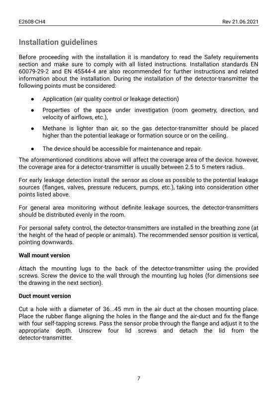
Installation guidelines
Before proceeding with the installation it is mandatory to read the Safety requirementssection and make sure to comply with all listed instructions. Installation standards EN60079-29-2 and EN 45544-4 are also recommended for further instructions and relatedinformation about the installation. During the installation of the detector-transmitter thefollowing points must be considered:
● Application (air quality control or leakage detection)
● Properties of the space under investigation (room geometry, direction, andvelocity of airflows, etc.),
● Methane is lighter than air, so the gas detector-transmitter should be placedhigher than the potential leakage or formation source or on the ceiling.
● The device should be accessible for maintenance and repair.
The aforementioned conditions above will affect the coverage area of the device. however,the coverage area for a detector-transmitter is usually between 2.5 to 5 meters radius.
For early leakage detection install the sensor as close as possible to the potential leakagesources (flanges, valves, pressure reducers, pumps, etc.), taking into consideration otherpoints listed above.
For general area monitoring without definite leakage sources, the detector-transmittersshould be distributed evenly in the room.
For personal safety control, the detector-transmitters are installed in the breathing zone (atthe height of the head of people or animals). The recommended sensor position is vertical,pointing downwards.
Wall mount version
Attach the mounting lugs to the back of the detector-transmitter using the providedscrews. Screw the device to the wall through the mounting lug holes (for dimensions seethe drawing in the next section).
Duct mount version
Cut a hole with a diameter of 36...45 mm in the air duct at the chosen mounting place.Place the rubber flange aligning the holes in the flange and the air-duct and fix the flangewith four self-tapping screws. Pass the sensor probe through the flange and adjust it to theappropriate depth. Unscrew four lid screws and detach the lid from thedetector-transmitter.
7

E2608-CH4 Rev 21.06.2021
Mounting dimensions
Wall mount version with mounting lugs
Duct mount version
8

E2608-CH4 Rev 21.06.2021
Sensor probe handling
The wall-mount version of the detector-transmitter is available with a remote probe (seedrawing below for dimensions). The remote probe is connected to the main unit with ashielded cable. The default remote probe cable length is 3 m.
A) Wall mount remote probe with fixing clamp (default version),B) Remote probe with rubber flange and three self-tapping screws (on request)
The sensor probes of all types are equipped with a hydrophobic microporous PTFE filter toprotect the sensor from dust, dirt, and water drops. The filter should be replaced if it getsstrongly contaminated. To replace the PTFE filter, unscrew the sensor head cap andremove the old filter. Place a new filter into the cap and tighten it again.
NOTE! Never stab or press the filter near its center where the sensor is located since thismay damage the sensor. Do not remove the filter as it may cause the device to showincorrect values and/or break the sensor.
The recommended orientation of the sensor probe is vertical with the sensor tip pointingdownwards. This prevents the possible accumulation of condensed water on the sensorprotection filter.
Gas sensor replacement procedures
1. Remove the sensor head cap from the device (or the remote probe),2. Remove the PTFE filter (if it is not removed within the cap),3. Remove the O-ring rubber,4. Detach the catalytic (pellistor) sensor from the device,5. Insert the new catalytic (pellistor) sensor inside,6. Put back the O-ring rubber, PTFE filter, and the head cap, respectively.
Note! Metal oxide semiconductor sensors are not replaceable.
9

E2608-CH4 Rev 21.06.2021
Electrical connections
Unscrew four lid screws and detach the lid from the device. Use the M16 cable gland to letin cables of the power supply and of the external devices. Attach the power cable to thedevice without turning it on. Using the connection diagram below, connect the analogoutputs and digital interface terminals to the relevant devices according to your tasks.
Version without PSU Version with PSU
Jumpers
J1 OUT1 type (open: 4-20 mA; closed 0-10 V)
J2 OUT2 type (open: 4-20 mA; closed 0-10 V)
X6 Reset Modbus network parameters to default
X4 terminals
OUT1 4-20 mA / 0-10 V output
OUT2 4-20 mA / 0-10 V output
0V 0 V / 24 VAC Neutral (optional)
A RS485 A / Data +
B RS485 B / Data -
+U +24 VDC / 24 VAC Phase (optional)
10

E2608-CH4 Rev 21.06.2021
X5 terminals (optional)
L 90…265 VAC Phase
N 90…265 VAC Neutral
RE1 NO Relay 1, normally open terminal
RE1 COM Relay 1, common terminal
RE2 NO Relay 2, normally open terminal
RE2 COM Relay 2, common terminal
The screwless quick connect spring terminals on the E2608 series devices are suitable fora wide range of wires with a cross-section of 0.2...1.5 mm2. We recommend to strip thewire end by 8...9 mm and use wire end sleeves.
To connect the wire, insert the wire end into the terminal hole. To disconnect, push thespring-loaded terminal lever, pull the wire out, and release the lever.
Use a twisted-pair cable, e.g. LiYY TP 2×2×0.5 mm2 or CAT 5, to connect the device to theRS485 network. A and B on the device represent DATA+ and DATA-, respectively, polaritymust be respected when connecting to an external RS485 network.
Both analog outputs can be independently changed between 4-20 mA and 0-10 V typeusing jumpers J1 (OUT1) and J2 (OUT2). By closing pins on a specific jumper the relatedoutput is 0-10 V, with an open jumper the output is 4-20 mA. Power restart is required afterchanging the position of the jumpers
NOTE! The outputs are not galvanically isolated from the external power supply and sharea common 0V. Allowed load resistance limits are stated in the Specifications table. Topower, the instrument from an external power source, connect terminals 0V and +U to thesource. If the integrated mains power supply module is used, connect terminals L and N tothe mains.
NOTE! Actuator short-circuits should be avoided, to protect the instrument relays usingexternal fuses or safety switches.
11

E2608-CH4 Rev 21.06.2021
Correct and incorrect cabling for 24 VAC
12

E2608-CH4 Rev 21.06.2021
Operation
Turn on the power. The instrument warm-up time for both types of sensors takes about 5minute after switching on and final sensor stabilization time to maximum accuracy takesabout 1 hour. The operating status is indicated by the LED on the PCB of the device. Thecontrol LED (red) response to different processes is presented in the following table:
Mode LED mode
During calibration mode or sensor heatingperiod (if activated) 0.5 Hz (50% on, 50% off)
Relay 1 turned on Blinking 1 Hz (50% on, 50% off)
Relay 2 turned on Blinking 2 Hz (50% on, 50% off)
During the Modbus communication cycle Short on-off pulses
Normal operating/measurement Continuously on or off
Make sure that the detector-transmitter is properly mounted, the external devicesconnected, the power LED (green) on, and the control LED (red) is constantly lit. Place thelid back and fix it with the screws. The device is ready to use.
Maintenance
Do not perform any maintenance operation with the power on.
Clean the device with a soft damp cloth. Do not use any abrasive cleaning agents. Do notimmerse the device in water or any cleaning media.
Calibration
E2608-CH4 detector-transmitters have been calibrated by the Manufacturer with standardgas mixtures before delivery. Provided that the sensor is used under moderate conditions,field recalibration is recommended once or twice a year. Please contact your dealer formore information.
13

E2608-CH4 Rev 21.06.2021
Delivery set
● Detector-transmitter E2608 (wall mount or duct mount version)
● Mounting accessories:
○ 4 cross-shaped mounting lug with screws and 4 screws with plasticdowels for wall mount version
○ Square Rubber flange for Duct mount option
○ Round rubber flange for Remote probe option
○ Fixing clamp for Remote probe option
Order code for E2608-CH4 options
E2608 options Order code
Remote probe, 3 m cable E2608-CH4-RP33-3
Remote probe, 10 m cable E2608-CH4-RP33-10
Duct mount option, stem Ø35×L230 mm E2608-CH4-DM
Integrated 90...265 V mains power supply module E2608-CH4-230
Integrated 24 VAC power supply module E2608-CH4-24VAC
Remote LCD single value display, wall mount box 115× 65 × 40mm, 3 m cable
E2608-CH4-RLCD3
14

E2608-CH4 Rev 21.06.2021
ConfiguringA standard configuration kit includes a USB-RS485 converter, fixed flow regulator, gastubing with applicators, and a software pack. Please contact your Seller for moreinformation.
Gas detector-transmitters E2608 share all functionalities of the PluraSens® multifunctionaldetector-transmitter platform. The features and options include:
● Digital output change rate-limiting filter● Digital integrating (averaging) filter● Free assignment of each analog output to the chosen parameter● Flexible setting of analog output scales for each output● Output zero and slope adjustment for calibration● Free assignment of each of two relays to the chosen parameter● Several relay control logic modes● Switch delays and minimum on/off state durations for each relay
The output scales can be changed by Modbus commands by using the configurationsoftware and the standard configuration kit (see Modbus RTU Communication).
Return to default settings
To reset the device’s Slave ID, baud rate, and stop bit numbers to factory settings, proceedas follows:
1. De-energize the device2. Connect the X6 jumper3. Turn on the device4. De-energize the device5. Disconnect the X6 jumper6. Turn on the device
15
E2608-CH4 Rev 21.06.2021
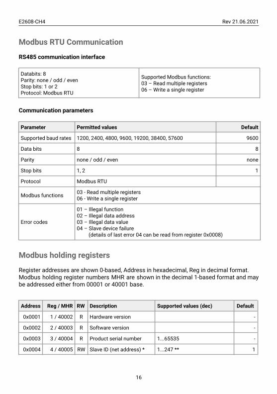
Modbus RTU Communication
RS485 communication interface
Databits: 8Parity: none / odd / evenStop bits: 1 or 2Protocol: Modbus RTU
Supported Modbus functions:03 – Read multiple registers06 – Write a single register
Communication parameters
Parameter Permitted values Default
Supported baud rates 1200, 2400, 4800, 9600, 19200, 38400, 57600 9600
Data bits 8 8
Parity none / odd / even none
Stop bits 1, 2 1
Protocol Modbus RTU
Modbus functions 03 - Read multiple registers06 - Write a single register
Error codes
01 – Illegal function02 – Illegal data address03 – Illegal data value04 – Slave device failure
(details of last error 04 can be read from register 0x0008)
Modbus holding registers
Register addresses are shown 0-based, Address in hexadecimal, Reg in decimal format.Modbus holding register numbers MHR are shown in the decimal 1-based format and maybe addressed either from 00001 or 40001 base.
Address Reg / MHR RW Description Supported values (dec) Default
0x0001 1 / 40002 R Hardware version -
0x0002 2 / 40003 R Software version -
0x0003 3 / 40004 R Product serial number 1...65535 -
0x0004 4 / 40005 RW Slave ID (net address) * 1...247 ** 1
16

E2608-CH4 Rev 21.06.2021
0x0005 5 / 40006 RW Baud rate * 1200, 2400, 4800, 9600, 19200,38400, 57600 9600
0x0006 6 / 40007 RW Response delay, ms 1...255 10
0x0007 7 / 40008 RW Stop bits, parity bit *
1 – No parity bit, 1 stop bit(default after factory reset)2 – No parity bit, 2 stop bits3 – Odd parity, 1 stop bit4 – Even parity, 1 stop bitNOTE: 3 and 4 are availablestarting from the Softwareversion 0x218 (dec. 536)
1
0x0008 8 / 40009 R Last error code 1...255 -
0x0011 17 / 40018 RWTechnological:age of last data in seconds(read) / restart (write)
0...65535 s (read),writing 42330 restarts theinstrument
-
Address Reg / MHR RW Description Supported values (dec) Default
0x00A5 165 / 40166 RW Zero adjustment for gasdata, ADC -32000...+32000 ADC units 0
0x00A6 166 / 40167 RW Slope adjustment for gasdata 1...65535 512
0x00A7 167 / 40168 RW Change rate limit for gasdata, units / s 1...32000, 0 - no limit 0
0x00A8 168 / 40169 RW Integrating filter timeconstant, s
1...32000 (seconds),0 - no filter 0
0x00C9 201 / 40202 RW Parameter tied to analogoutput 1
0 – None2 – Gas concentration9 – Forced Modbus control,
value set in MHR / 40204
2
0x00CA 202 / 40203 RW Parameter tied to analogoutput 2
0 – None2 – Gas concentration9 – Forced Modbus control,
value set in MHR / 40205
2
0x00CB 203 / 40204 RW Forced value for analogoutput 1***
0...1000(0.0%...100.0% of output scale) 0
0x00CC 204 / 40205 RW Forced value for analogoutput 2***
0...1000(0.0%...100.0% of output scale) 0
0x00D3 211 / 40212 RW Parameter tied to relay 0 –none 2
17

E2608-CH4 Rev 21.06.2021
RE1 2 – gas concentration9 – control by Modbus control,state set in MHR / 40214
0x00D4 212 / 40213 RW Parameter tied to relayRE2
0 – none2 – gas concentration9- – control by Modbus control,state set in MHR / 40215
2
0x00D5 213 / 40214 RW Forced state for relayRE1*** 0 –off, 1 – on 0
0x00D6 214/ 40215 RW Forced state for relayRE2*** 0 – off, 1 – on 0
0x00D7 215 / 40216 RW Switching delay for relayRE1 0...1000 (s) 0
0x00D8 216 / 40217 RW Switching delay for relayRE2 0...1000 (s) 0
0x00D9 217 / 40218 RW Minimal on/off time forrelay RE1
0...1000 (s) 0
0x00DA 218 / 40219 RW Minimal on/off time forrelay RE2
0...1000 (s) 0
Address Reg / MHR RW Description Supported values (dec) Default
0x00DB 219 /40220 RW Control logic for relay RE1
0 – none1 – relay on at high values2 – relay on at low values3 – relay on at values withinthe range4 – relay on for the valuesout of the range
0
0x00DC 220 /40221 RW Control logic for relay RE2
0 – none1 – relay on at high values2 – relay on at low values3 – relay on at values withinthe range4 – relay on for the valuesout of the range
0
18

E2608-CH4 Rev 21.06.2021
0x00DD 221 /40222 RW LOW setpoint for relay
RE1 0...65535 (gas units) seeSpecifications
0x00DE 222 /40223 RW HIGH setpoint for relay
RE1 0...65535 (gas units) seeSpecifications
0x00DF 223 /40224 RW LOW setpoint for relay
RE2 0...65535 (gas units) seeSpecifications
0x00E0 224 /40225 RW HIGH setpoint for relay
RE2 0...65535 (gas units) seeSpecifications
0x00FF 255 /40256 RW Sensor, analog outputs,
LED and buzzer status
bit[0]=0/1 – sensorpresent/absent, RObit[1]=0/1 – analog outputsdeactivated/activatedbit[2]=0/1 – in case thesensor is absent, turnsignaling off/on analogoutput1bit[3]=0/1 – in case thesensor is absent, turn onsignaling with lowcurrent/high current onanalog output1; if bit[2]=0this bit will be ignoredbit[4]=0/1 – in case ofsensor absent, turn signalingoff/on analog output2bit[5]=0/1 – in case ofsensor absent, turn onsignaling with lowcurrent/high current onanalog output2; if bit[4]==0this bit will be ignoredbit[6]=0/1 – current/voltageoutput detected on output1,RObit[7]=0/1 – current/voltageoutput detected on output2,RObit[8]=0/1 – LEDdeactivated/activatedbit[9]=0/1 – buzzerdeactivated/activatedbit[10]=0/1 - LED is on/off innormal conditionbit[11]=0/1 - 1 Hz (50% on,50% off) LED signal off/on ifrelay1 turned onbit[12]=0/1 - 2 Hz (50% on,
userdefined
19

E2608-CH4 Rev 21.06.2021
50% off) LED signal off/on ifrelay2 turned on
0x0101 257 /40258 R Raw gas sensor data 0...4095, ADC units
0x0103 259 /40260 R Gas concentration,
gas units 0...65535, gas units
0x0105 261 /40262 RW 0% value
for analog output 1 -32000...+32000, gas units Userdefined
0x0106 262 /40263 RW 100% value
for analog output 1 -32000...+32000, gas units Userdefined
0x0107 263 /40264 RW 0% value
for analog output 2 -32000...+32000, gas units Userdefined
0x0108 264 /40265 RW 100% value
for analog output 2 -32000...+32000, gas units Userdefined
* – The new value is applied after restart.
** – Broadcast slave ID 0 can be used to assign a new ID to the instrument with anunknown ID. When addressing by ID 0 the device shall be the only Modbus instrument inthe network. The device will not respond to the Master command when addressed by ID 0.
*** – This value is dynamic and not kept in EEPROM after a restart.
20

E2608-CH4 Rev 21.06.2021
Warranty
This product is warranted to be free from defects in material and workmanship for a periodof one year from the date of the original sale. During this warranty period, the Manufacturerwill, at its option, either repair or replace a product that proves to be defective. Thiswarranty is void if the product has been operated in conditions outside ranges specified bythe Manufacturer or damaged by customer error or negligence or if there has been anunauthorized modification.
Manufacturer contacts
Evikon MCI OÜ
Teaduspargi 7/9, Tartu50411 [email protected]
21


