19
PluraSens ® Refrigerant Transmitter E2618-HFC User Manual

PluraSens®
Refrigerant Transmitter
E2618-HFC
User Manual

E2618-HFC Rev 21.06.2021
Table of contentsHydrofluorocarbons 3
Specifications 5
Product description 6
Safety requirements 6
Operating conditions 6
Installation guidelines 7Wall mount version 7Duct mount version 7
Mounting dimension 8
Sensor probe handling 9
Gas sensor replacement procedures 9
Electrical connections 10Correct and incorrect cabling for 24 VAC 11
Operation 12
Maintenance 12
Calibration 12
Delivery set 13Order code for E2618-HFC options 13
Configuring 14
Return to default settings 14
Modbus RTU Communication 15RS485 communication interface 15Communication parameters 15
Modbus holding registers 15
Warranty 19
Manufacturer contacts 19
2
E2618-HFC Rev 21.06.2021
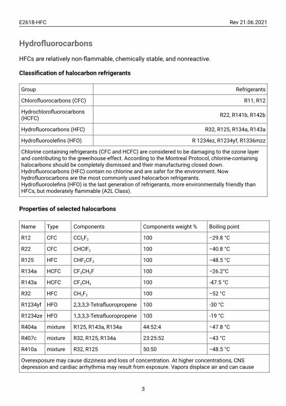
Hydrofluorocarbons
HFCs are relatively non-flammable, chemically stable, and nonreactive.
Classification of halocarbon refrigerants
Group Refrigerants
Chlorofluorocarbons (CFC) R11, R12
Hydrochlorofluorocarbons(HCFC) R22, R141b, R142b
Hydrofluorocarbons (HFC) R32, R125, R134a, R143a
Hydrofluoroolefins (HFO) R 1234ez, R1234yf, R1336mzz
Chlorine containing refrigerants (CFC and HCFC) are considered to be damaging to the ozone layerand contributing to the greenhouse effect. According to the Montreal Protocol, chlorine-containinghalocarbons should be completely dismissed and their manufacturing closed down.Hydrofluorocarbons (HFC) contain no chlorine and are safer for the environment. Nowhydrofluorocarbons are the most commonly used halocarbon refrigerants.Hydrofluoroolefins (HFO) is the last generation of refrigerants, more environmentally friendly thanHFCs, but moderately flammable (A2L Class).
Properties of selected halocarbons
Name Type Components Components weight % Boiling point
R12 CFC CCl2F2 100 −29.8 °C
R22 CFC CHClF2 100 −40.8 °C
R125 HFC CHF2CF3 100 −48.5 °C
R134a HCFC CF3CH2F 100 −26.2°C
R143a HCFC CF3CH3 100 -47.5 °C
R32 HFC CH2F2 100 −52 °C
R1234yf HFO 2,3,3,3-Tetrafluoropropene 100 -30 °C
R1234ze HFO 1,3,3,3-Tetrafluoropropene 100 -19 °C
R404a mixture R125, R143a, R134a 44:52:4 −47.8 °C
R407c mixture R32, R125, R134a 23:25:52 −43 °C
R410a mixture R32, R125 50:50 −48.5 °C
Overexposure may cause dizziness and loss of concentration. At higher concentrations, CNSdepression and cardiac arrhythmia may result from exposure. Vapors displace air and can cause
3

E2618-HFC Rev 21.06.2021
asphyxiation in confined spaces. At higher temperatures (>250°C) decomposition products mayinclude hydrofluoric acid (HF) and carbonyl halides.An escape of refrigerant through a leak may damage the refrigerating facilities.
4

E2618-HFC Rev 21.06.2021
Specifications
Sampling method Diffusion
Sensor type Metal oxide semiconductor (NDIR on demand)
Typical detection range 0...1000 ppm
Resolution / digital unit 1 ppm
Response time T90 <120 s
Sensor lifetime > 5 years
Calibration interval 12 months
Signal update Every 1 second
Load resistance RL < (Us - 2 V) / 22 mA for 4-20 mARL > 250 kOhm for 0-10 V mode
Digital interface RS485, Modbus RTU protocolNo galvanic isolation
Power supply options 11...30 VDC or 24 VAC
Power consumption < 2 VA
Analog outputs 2 × 4-20 mA / 0-10 V, user settable
Outputs assignment OUT1 2 gas; OUT2 2 gas
Cable connections Screwless spring-loaded terminals
Enclosure Grey ABS, wall or duct mount, protection class IP65
Dimensions H82 × W80 × D55 mm
CE marking
According to 2014/30/EU and 2014/35/EU, EN 50491-4-1:2012EN 61000-6-3:2020, EN 61326-1:2013(EMC, emissions)
EN 61000-6-1:2019, EN 61000-6-2:2019(EMC, Immunity)EN 60079-29-1:2016, EN 60079-29-2:2015 and EN 60079-29-3:2014
Operating conditions
-30...+60 °C<95% RH non-condensing, 0,9...1,1 atm
Explosion-safe areasNormal ambient oxygen level
Avoid strong mechanical shock, vibrations, or EMIAvoid exposure to corrosive gases or silicone-containing products
Other options
Remote probe Protection IP65, default cable length 3.0 m;max height 80 mm, max diameter 65 mm
5

E2618-HFC Rev 21.06.2021
Product description
E2618 series transmitters belong to the PluraSens® family of multifunctional measurementinstruments. The instruments utilize gas sensors of various types with excellentrepeatability, stability, and long lifetime.
E2618 series provide two independent analog outputs OUT1 and OUT2, user-selectable to4-20 mA or 0-10 V, proportional to the chosen scale for gas concentration. RS485 ModbusRTU digital communication interface allows easy instrument configuration and integrationinto various automation systems.
Remote probe and duct mount versions are available.
The version of your transmitter is marked on the package. If⚠ symbol is marked on theproduct, consult the documentation for further information.
Safety requirements
Misuse will impair the protection of the product. Always adhere to the safety provisionsapplicable in the country of use.
Do not perform any maintenance operation with the power on. Do not let water or foreignobjects inside the device.
Removal of the PCB from the enclosure voids the warranty. Do not touch the electroniccomponents directly, as they are sensitive to static electricity.
Connection diagrams can be found in the electrical connections section. The device mightnot perform correctly or be damaged if the wrong power supply is connected.
External circuits connected to the equipment should have sufficient insulation ratingaccording to the environmental conditions and equipment power.
A disconnecting device that is marked as such and easily accessible should be included inthe installation of this product.
Operating conditions
The device should be used both in a non-hazardous area and in a basic electromagneticenvironment, where the latter is defined in EN 61326-1. Avoid strong mechanical shock andvibrations. Avoid corrosive atmosphere and areas highly contaminated with dust, oil mist,etc. Keep the instrument away from direct sunlight. A sudden temperature or humiditychange might affect the sensitivity of the sensor.
6
E2618-HFC Rev 21.06.2021
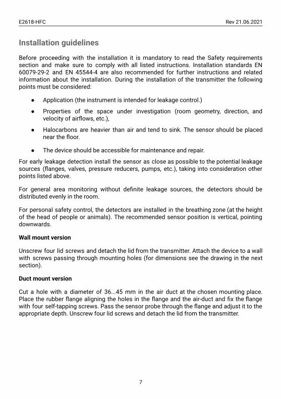
Installation guidelines
Before proceeding with the installation it is mandatory to read the Safety requirementssection and make sure to comply with all listed instructions. Installation standards EN60079-29-2 and EN 45544-4 are also recommended for further instructions and relatedinformation about the installation. During the installation of the transmitter the followingpoints must be considered:
● Application (the instrument is intended for leakage control.)
● Properties of the space under investigation (room geometry, direction, andvelocity of airflows, etc.),
● Halocarbons are heavier than air and tend to sink. The sensor should be placednear the floor.
● The device should be accessible for maintenance and repair.
For early leakage detection install the sensor as close as possible to the potential leakagesources (flanges, valves, pressure reducers, pumps, etc.), taking into consideration otherpoints listed above.
For general area monitoring without definite leakage sources, the detectors should bedistributed evenly in the room.
For personal safety control, the detectors are installed in the breathing zone (at the heightof the head of people or animals). The recommended sensor position is vertical, pointingdownwards.
Wall mount version
Unscrew four lid screws and detach the lid from the transmitter. Attach the device to a wallwith screws passing through mounting holes (for dimensions see the drawing in the nextsection).
Duct mount version
Cut a hole with a diameter of 36...45 mm in the air duct at the chosen mounting place.Place the rubber flange aligning the holes in the flange and the air-duct and fix the flangewith four self-tapping screws. Pass the sensor probe through the flange and adjust it to theappropriate depth. Unscrew four lid screws and detach the lid from the transmitter.
7
E2618-HFC Rev 21.06.2021
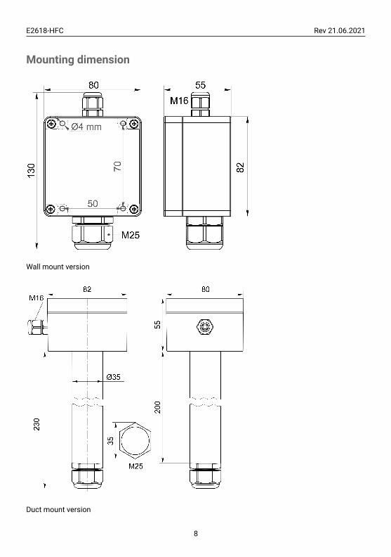
Mounting dimension
Wall mount version
Duct mount version
8

E2618-HFC Rev 21.06.2021
Sensor probe handling
The wall mount version of the transmitter is available with a remote probe (see drawingbelow for dimensions). The remote probe is connected to the main unit with a shieldedcable. The default remote probe cable length is 3 m.
A) Wall mount remote probe with fixing clamp (default version),B) Remote probe with rubber flange and three self-tapping screws (on request)
The sensor probes of all types are equipped with a hydrophobic microporous PTFE filter toprotect the sensor from dust, dirt, and water drops. The filter should be replaced if it getsstrongly contaminated. To replace the PTFE filter, unscrew the sensor head cap andremove the old filter. Place a new filter into the cap and tighten it again.
NOTE! Never stab or press the filter near its center where the sensor is located since thismay damage the sensor. Do not remove the filter as it may cause the device to showincorrect values and/or break the sensor.
The recommended orientation of the sensor probe is vertical with the sensor tip pointingdownwards. This prevents the possible accumulation of condensed water on the sensorprotection filter.
Gas sensor replacement procedures
1. Remove the sensor head cap from the device,2. Remove the PTFE filter (if it is not removed within the cap),3. Remove the O-ring rubber,4. Detach the electrochemical sensor from the device,5. Insert the new electrochemical sensor inside,6. Put back the O-ring rubber, PTFE filter, and the head cap, respectively.
9

E2618-HFC Rev 21.06.2021
Electrical connections
Unscrew four lid screws and detach the lid from the device. Use the M16 cable gland to letin cables of the power supply and of the external devices. Attach the power cable to thedevice without turning it on. Using the connection diagram below, connect the analogoutputs and digital interface terminals to the relevant devices according to your tasks.
PCB without PSU and relays
Jumpers
J1 OUT1 type (open: 4-20 mA; closed 0-10 V)
J2 OUT2 type (open: 4-20 mA; closed 0-10 V)
X6 Reset Modbus network parameters to default
X4 terminals
OUT1 4-20 mA / 0-10 V output
OUT2 4-20 mA / 0-10 V output
0V 0 V / 24 VAC Neutral (optional)
A RS485 A / Data +
B RS485 B / Data -
+U +24 VDC / 24 VAC Phase (optional)
10

E2618-HFC Rev 21.06.2021
The screwless quick connect spring terminals on the E2618 series devices are suitable fora wide range of wires with a cross-section of 0.2...1.5 mm2. We recommend striping thewire end by 8...9 mm and using wire end sleeves.
To connect the wire, insert the wire end into the terminal hole. To disconnect, push thespring-loaded terminal lever, pull the wire out, and release the lever.
Use a twisted-pair cable, e.g. LiYY TP 2×2×0.5 mm2 or CAT 5, to connect the device to theRS485 network. A and B on the device represent DATA+ and DATA- respectively, polaritymust be respected when connecting to an external RS485 network.
Both analog outputs can be independently changed between 4-20 mA and 0-10 V typeusing jumpers J1 (OUT1) and J2 (OUT2). By closing pins on a specific jumper the relatedoutput is 0-10 V, with an open jumper the output is 4-20 mA. Power restart is required afterchanging the position of the jumpers.
Correct and incorrect cabling for 24 VAC
11

E2618-HFC Rev 21.06.2021
Operation
Turn on the power. The instrument warm-up time takes about 1 minute after switching onand the final sensor stabilization time to maximum accuracy takes <60 minutes. Theoperating status is indicated by the LED on the PCB of the device. The control LED (red)response to different processes is presented in the following table:
Mode LED mode
During calibration mode or sensor heatingperiod (if activated) 0.5 Hz (50% on, 50% off)
During Modbus communication cycle Short on-off pulses
Normal operating/measurement Continuously on or off
Make sure that the transmitter is properly mounted, the external devices connected, powerLED (green) on and control LED (red) constantly lit. Place the lid back and fix it with thescrews. The device is ready to use.
Maintenance
Do not perform any maintenance operation with the power on.
Clean the device with a soft damp cloth. Do not use any abrasive cleaning agents. Do notimmerse the device in water or any cleaning media.
Calibration
E2618-HFC gas transmitters have been calibrated by the Manufacturer with standard gasmixtures before delivery. Provided that the sensor is used under moderate conditions, therecommended interval for field recalibration is 12 months. Please contact your dealer formore information.
12

E2618-HFC Rev 21.06.2021
Delivery set
● Gas transmitter E2618 (wall mount, duct mount, or remote probe version)
● Mounting accessories:
○ 4 screws with plastic dowels for wall mount version
○ Square Rubber flange for Duct mount option
○ Round rubber flange for Remote probe option
○ Fixing clamp for Remote probe option
Order code for E2618-HFC options
E2618 options Order code
Remote probe, 3 m cable E2618-HFC-RP33-3
Remote probe, 10 m cable E2618-HFC-RP33-10
Duct mount option, stem Ø35×L230 mm E2618-HFC-DM
Integrated 24 VAC power supply module E2618-HFC-24VAC
Remote LCD single value display, wall mount box115 × 65 × 40mm, 3 m cable
E2618-HFC-RLCD3
13

E2618-HFC Rev 21.06.2021
ConfiguringA standard configuration kit includes a USB-RS485 converter, fixed flow regulator, gastubing with applicators, and a software pack. Please contact your Seller for moreinformation.
Gas transmitters E2618 share all functionalities of the PluraSens® multifunctionaltransmitter platform. The features and options include:
● Digital output change rate-limiting filter● Digital integrating (averaging) filter● Free assignment of each analog output to the chosen parameter● Flexible setting of analog output scales for each output● Output zero and slope adjustment for calibration
The output scales can be changed by Modbus commands by using the configurationsoftware and the standard configuration kit (see Modbus RTU Communication).
Return to default settings
To reset the device’s Slave ID, baud rate, and stop bit numbers to factory settings, proceedas follows:
1. De-energize the device2. Connect the X6 jumper3. Turn on the device4. De-energize the device5. Disconnect the X6 jumper6. Turn on the device
14

E2618-HFC Rev 21.06.2021
Modbus RTU Communication
RS485 communication interface
Databits: 8Parity: none / odd / evenStop bits: 1 or 2Protocol: Modbus RTU
Supported Modbus functions:03 – Read multiple registers06 – Write a single register
Communication parameters
Parameter Permitted values Default
Supported baud rates 1200, 2400, 4800, 9600, 19200, 38400, 57600 9600
Data bits 8 8
Parity none / odd / even none
Stop bits 1, 2 1
Protocol Modbus RTU
Modbus functions 03 - Read multiple registers06 - Write a single register
Error codes
01 – Illegal function02 – Illegal data address03 – Illegal data value04 – Slave device failure
(details of last error 04 can be read from register 0x0008)
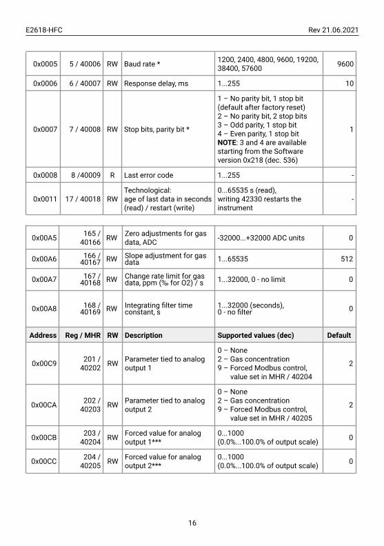
Modbus holding registers
Register addresses are shown 0-based, Address in hexadecimal, Reg in decimal format.Modbus holding register numbers MHR are shown in the decimal 1-based format and maybe addressed either from 00001 or 40001 base.
Address Reg / MHR RW Description Supported values (dec) Default
0x0001 1 / 40002 R Hardware version -
0x0002 2 / 40003 R Software version -
0x0003 3 / 40004 R Product serial number 1...65535 -
0x0004 4 / 40005 RW Slave ID (net address) * 1...247 ** 1
15
E2618-HFC Rev 21.06.2021
0x0005 5 / 40006 RW Baud rate * 1200, 2400, 4800, 9600, 19200,38400, 57600 9600
0x0006 6 / 40007 RW Response delay, ms 1...255 10
0x0007 7 / 40008 RW Stop bits, parity bit *
1 – No parity bit, 1 stop bit(default after factory reset)2 – No parity bit, 2 stop bits3 – Odd parity, 1 stop bit4 – Even parity, 1 stop bitNOTE: 3 and 4 are availablestarting from the Softwareversion 0x218 (dec. 536)
1
0x0008 8 /40009 R Last error code 1...255 -
0x0011 17 / 40018 RWTechnological:age of last data in seconds(read) / restart (write)
0...65535 s (read),writing 42330 restarts theinstrument
-
0x00A5 165 /40166 RW Zero adjustments for gas
data, ADC -32000...+32000 ADC units 0
0x00A6 166 /40167 RW Slope adjustment for gas
data 1...65535 512
0x00A7 167 /40168 RW Change rate limit for gas
data, ppm (‰ for O2) / s 1...32000, 0 - no limit 0
0x00A8 168 /40169 RW Integrating filter time
constant, s1...32000 (seconds),0 - no filter 0
Address Reg / MHR RW Description Supported values (dec) Default
0x00C9 201 /40202 RW Parameter tied to analog
output 1
0 – None2 – Gas concentration9 – Forced Modbus control,
value set in MHR / 40204
2
0x00CA 202 /40203 RW Parameter tied to analog
output 2
0 – None2 – Gas concentration9 – Forced Modbus control,
value set in MHR / 40205
2
0x00CB 203 /40204 RW Forced value for analog
output 1***0...1000(0.0%...100.0% of output scale) 0
0x00CC 204 /40205 RW Forced value for analog
output 2***0...1000(0.0%...100.0% of output scale) 0
16

E2618-HFC Rev 21.06.2021
0x00FF 255 /40256 RW Sensor, analog outputs,
LED and buzzer status
bit[0]=0/1 – sensorpresent/absent, RObit[1]=0/1 – analog outputsdeactivated/activatedbit[2]=0/1 – in case the sensoris absent, turn signaling off/onanalog output1bit[3]=0/1 – in case the sensoris absent, turn on signaling withlow current/high current onanalog output1; if bit[2]=0 thisbit will be ignoredbit[4]=0/1 – in case of sensorabsent, turn signaling off/onanalog output2bit[5]=0/1 – in case of sensorabsent, turn on signaling withlow current/high current onanalog output2; if bit[4]==0 thisbit will be ignoredbit[6]=0/1 – current/voltageoutput detected on output1, RObit[7]=0/1 – current/voltageoutput detected on output2, RObit[8]=0/1 – LEDdeactivated/activatedbit[9]=0/1 – buzzerdeactivated/activated (always0 for E2618)bit[10]=0/1 - LED is on/off innormal condition
Address Reg / MHR RW Description Supported values (dec) Default
0x0101 257 /40258 R Raw gas sensor data 0...4095, ADC units
0x0103 259 /40260 R Gas concentration,
gas units 0...65535, gas units
0x0105 261 /40262 RW 0% value
for analog output 1-32000...+32000(gas unit/°C)
Userdefined
0x0106 262 /40263 RW 100% value
for analog output 1-32000...+32000(gas unit/°C)
Userdefined
0x0107 263 /40264 RW 0% value
for analog output 2-32000...+32000(gas unit/°C)
Userdefined
0x0108 264 /40265 RW 100% value
for analog output 2-32000...+32000(gas unit/°C)
Userdefined
17

E2618-HFC Rev 21.06.2021
* – The new value is applied after restart.
** – Broadcast slave ID 0 can be used to assign a new ID to the instrument with anunknown ID. When addressing by ID 0 the device shall be the only Modbus instrument inthe network. The device will not respond to the Master command when addressed by ID 0.
*** – This value is dynamic and not kept in EEPROM after a restart.
18

E2618-HFC Rev 21.06.2021
Warranty
This product is warranted to be free from defects in material and workmanship for a periodof one year from the date of the original sale. During this warranty period, the Manufacturerwill, at its option, either repair or replace a product that proves to be defective. Thiswarranty is void if the product has been operated in conditions outside ranges specified bythe Manufacturer or damaged by customer error or negligence or if there has been anunauthorized modification.
Manufacturer contacts
Evikon MCI OÜ
Teaduspargi 7/9, Tartu50411 [email protected]
19


